

Page 1
SEPTEMBER 2002
ACR9000A
Page 2

1
THE SERVSWITCH™ FAMILY
Welcome to the ServSwitch
TM
Family!
Thank you for purchasing a BLACK BOX®ServSwitch™Brand KVM switch! We
appreciate your business, and we think you’ll appreciate the many ways that your
new ServSwitch keyboard/video/mouse switch will save you money, time, and
effort.
That’s because our ServSwitch family is all about breaking away from the
traditional, expensive model of computer management. You know, the one-sizefits-all-even-if-it-doesn’t model that says, “One computer gets one user station, no
more, no less.” Why not a single user station (monitor, keyboard, and mouse) for
multiple computers—even computers of different platforms? Why not a pair of
user stations, each of which can control multiple computers? Why not multiple
user stations for the same computer?
With our ServSwitch products, there’s no reason why not. We carry a broad line
of robust solutions for all these applications. Do you have just two PCs, and need
an economical alternative to keeping two monitors, keyboards, and mice on your
desk? Or do you need to share dozens of computers, including a mix of IBM
®
PC,
RS/6000
®
, Apple®Macintosh®, Sun Microsystems®, and SGI®compatibles among
multiple users with different access levels? Does your switch have to sit solidly on a
worktable and use regular everyday cables? Or does it have to be mounted in an
equipment rack and use convenient many-to-one cables? No matter how large or
small your setup is, no matter how simple or how complex, we’re confident we
have a ServSwitch system that’s just right for you.
The ServSwitch
™
family from Black Box—the one-stop answer for all your KVM-
switching needs!
*
This manual will tell you all about your new ServSwitch™ Ultra Remote,
including how to install, operate, and troubleshoot it. For an introduction to the
ServSwitch
Ultra Remote, see Chapter 3. The ServSwitch Ultra Remote product code
covered in this manual is:
ACR9000A
Page 3
2
SERVSWITCH™ ULTRA REMOTE
TRADEMARKS USED IN THIS MANUAL
BLACK BOX and the logo are registered trademarks, and ServSwitch and
ServSwitch Ultra Remote are trademarks, of Black Box Corporation.
Apple, Mac, and Macintosh are registered trademarks of Apple Computer, Inc.
IBM, PS/2, and RS/6000 are registered trademarks of International Business
Machines Corporation.
Microsoft, Windows, and Word are trademarks or registered trademarks of
Microsoft Corporation in the United States and/or other countries.
Sun and Sun Microsystems are registered trademarks of Sun Microsystems, Inc. in
the United States and other countries.
UL is a registered trademark of Underwriters Laboratories Inc.
Any other trademarks mentioned in this manual are acknowledged to be the property of the
trademark owners.
Page 4
3
FCC/IC STATEMENTS, EU DECLARATION OF CONFORMITY
FEDERAL COMMUNICATIONS COMMISSION AND INDUSTRY CANADA
RADIO-FREQUENCY INTERFERENCE STATEMENTS
This equipment generates, uses, and can radiate radio-frequency energy, and if not
installed and used properly, that is, in strict accordance with the manufacturer’s
instructions, may cause interference to radio communication. It has been tested
and found to comply with the limits for a Class A computing device in accordance
with the specifications in Subpart B of Part 15 of FCC rules, which are designed to
provide reasonable protection against such interference when the equipment is
operated in a commercial environment. Operation of this equipment in a
residential area is likely to cause interference, in which case the user at his own
expense will be required to take whatever measures may be necessary to correct the
interference.
Changes or modifications not expressly approved by the party responsible for
compliance could void the user’s authority to operate the equipment.
This digital apparatus does not exceed the Class A limits for radio noise emission from digital
apparatus set out in the Radio Interference Regulation of Industry Canada.
Le présent appareil numérique n’émet pas de bruits radioélectriques dépassant les limites
applicables aux appareils numériques de la classe A prescrites dans le Règlement sur le
brouillage radioélectrique publié par Industrie Canada.
EUROPEAN UNION DECLARATION OF CONFORMITY
This equipment is in conformity with the requirements of the European EMC
directive 89/336/EEC with respect to EN55022: (Class B), EN50082-1/EN60555-2,
and the Low Voltage Directive.
Page 5

4
SERVSWITCH™ ULTRA REMOTE
NORMAS OFICIALES MEXICANAS (NOM)
ELECTRICAL SAFETY STATEMENT
INSTRUCCIONES DE SEGURIDAD
1. Todas las instrucciones de seguridad y operación deberán ser leídas antes de
que el aparato eléctrico sea operado.
2. Las instrucciones de seguridad y operación deberán ser guardadas para
referencia futura.
3. Todas las advertencias en el aparato eléctrico y en sus instrucciones de
operación deben ser respetadas.
4. Todas las instrucciones de operación y uso deben ser seguidas.
5. El aparato eléctrico no deberá ser usado cerca del agua—por ejemplo, cerca
de la tina de baño, lavabo, sótano mojado o cerca de una alberca, etc..
6. El aparato eléctrico debe ser usado únicamente con carritos o pedestales que
sean recomendados por el fabricante.
7. El aparato eléctrico debe ser montado a la pared o al techo sólo como sea
recomendado por el fabricante.
8. Servicio—El usuario no debe intentar dar servicio al equipo eléctrico más allá
a lo descrito en las instrucciones de operación. Todo otro servicio deberá ser
referido a personal de servicio calificado.
9. El aparato eléctrico debe ser situado de tal manera que su posición no
interfiera su uso. La colocación del aparato eléctrico sobre una cama, sofá,
alfombra o superficie similar puede bloquea la ventilación, no se debe colocar
en libreros o gabinetes que impidan el flujo de aire por los orificios de
ventilación.
10. El equipo eléctrico deber ser situado fuera del alcance de fuentes de calor
como radiadores, registros de calor, estufas u otros aparatos (incluyendo
amplificadores) que producen calor.
11. El aparato eléctrico deberá ser connectado a una fuente de poder sólo del
tipo descrito en el instructivo de operación, o como se indique en el aparato.
Page 6

5
NOM STATEMENT
12. Precaución debe ser tomada de tal manera que la tierra fisica y la polarización
del equipo no sea eliminada.
13. Los cables de la fuente de poder deben ser guiados de tal manera que no
sean pisados ni pellizcados por objetos colocados sobre o contra ellos,
poniendo particular atención a los contactos y receptáculos donde salen del
aparato.
14. El equipo eléctrico debe ser limpiado únicamente de acuerdo a las
recomendaciones del fabricante.
15. En caso de existir, una antena externa deberá ser localizada lejos de las lineas
de energia.
16. El cable de corriente deberá ser desconectado del cuando el equipo no sea
usado por un largo periodo de tiempo.
17. Cuidado debe ser tomado de tal manera que objectos liquidos no sean
derramados sobre la cubierta u orificios de ventilación.
18. Servicio por personal calificado deberá ser provisto cuando:
A: El cable de poder o el contacto ha sido dañado; u
B: Objectos han caído o líquido ha sido derramado dentro del aparato; o
C: El aparato ha sido expuesto a la lluvia; o
D: El aparato parece no operar normalmente o muestra un cambio en su
desempeño; o
E: El aparato ha sido tirado o su cubierta ha sido dañada.
Page 7

6
SERVSWITCH™ ULTRA REMOTE
Safety Instructions
The ServSwitch™ Ultra Remote has been tested for conformance to safety
regulations and requirements, and has been certified for international use. Like all
electronic equipment, the Ultra Remote should be used with care. To protect
yourself from possible injury and to minimize the risk of damage to the Ultra
Remote and other equipment, read and follow these safety instructions.
CAUTION!
If the battery on the Ultra Remote’s motherboard fails, do not attempt to
replace it yourself unless you are directed to do so by a Black Box
technician. If you are directed to replace it, make sure to use the proper
type of battery. Using the wrong type of replacement battery creates the
risk of a fire or small-scale explosion. Dispose of used batteries
according to the battery manufacturer’s instructions. Follow all
instructions and warnings marked on the Ultra Remote.
• Do not attempt to service the Ultra Remote yourself.
• Do not use the Ultra Remote near water.
• Place the Ultra Remote only on a stable, clean, dry, flat surface or in a
19" equipment rack.
• Provide proper ventilation and air circulation for the Ultra Remote.
• Keep the Ultra Remote’s power cord and attached cables clear of obstructions
that might cause damage to them.
• Use only power cords, power transformer and connection cables designed for
the Ultra Remote.
• Use only a grounded (three-wire) electrical outlet.
• Keep liquids and potentially damaging objects away from the Ultra Remote.
Liquids and foreign objects might come in contact with voltage points, which
could create a risk of fire or electrical shock.
• Operate the Ultra Remote only when the cover of its enclosure is in place.
• Do not use liquid or aerosol cleaners to clean the Ultra Remote. Always unplug
the Ultra Remote from its electrical outlet before cleaning it.
Page 8

7
SAFETY INSTRUCTIONS
• Immediately unplug the Ultra Remote from the electrical outlet and call Black
Box to arrange for service if any of the following conditions occur:
– The power cord or attached cables have been damaged or frayed.
– The Ultra Remote has been exposed to any liquids.
– The Ultra Remote does not operate normally when all operating
instructions have been followed.
– The Ultra Remote has been dropped or its case has been damaged.
– The Ultra Remote begins performing poorly.
Page 9

8
SERVSWITCH™ ULTRA REMOTE
Contents
Chapter Page
1. Quick Start Guide ........................................................................................... 10
2. Specifications .................................................................................................. 15
3. Introduction ................................................................................................... 18
3.1 Overview ................................................................................................... 18
3.2 Features in Brief ........................................................................................ 18
3.3 Features in Detail ...................................................................................... 19
3.4 The Ultra Remote Illustrated ................................................................... 21
4. Getting Started ................................................................................................ 23
4.1 The Complete Package ........................................................................... 23
4.2 Other Things You Will Need .................................................................. 23
5. Hardware Installation ..................................................................................... 24
6. Initial Power-Up and Configuration .............................................................. 27
6.1 Powering Up the Ultra Remote .............................................................. 27
6.2 About Logins ........................................................................................... 28
6.3 Using the Connect Login for the First Time ......................................... 29
6.4 Using the Configure Login for the First Time ....................................... 30
6.5 The Configure Screen ............................................................................. 31
6.6 Connect Contention ............................................................................... 32
6.7 Password Defeat ....................................................................................... 32
7. Installing the Ultra Remote’s Viewer Software .............................................. 33
7.1 Requirements .......................................................................................... 33
7.2 Installing the Viewer with the Setup Wizard .......................................... 34
7.3 Using the Viewer for the First Time ....................................................... 35
8. The Viewer Screen .......................................................................................... 36
8.1 The Title Bar ........................................................................................... 36
8.2 Menu Commands .................................................................................... 36
8.3 The Toolbar ............................................................................................. 37
8.4 The Display Area ..................................................................................... 38
8.5 The Status Bar ......................................................................................... 38
8.6 The Windows Buttons ............................................................................. 38
8.7 Question-Mark Help ................................................................................ 39
Page 10

9
Chapter Page
9. The Viewer’s Menu Commands ..................................................................... 40
9.1 The File Menu ......................................................................................... 40
9.2 The Connect Menu ................................................................................. 41
9.3 The View Menu ....................................................................................... 42
9.4 The Shortcuts Menu ................................................................................ 45
9.5 The Settings Menu .................................................................................. 46
9.6 The Help Menu ....................................................................................... 47
10. Configuration Settings ................................................................................... 48
10.1 Connections ........................................................................................... 48
10.2 Keyboard and Mouse ............................................................................. 50
10.2.1 Hotkeys ...................................................................................... 50
10.2.2 Mouse Escape Movements ........................................................ 52
10.2.3 KVM Switch ............................................................................... 53
10.2.4 Security ...................................................................................... 55
10.2.5 User Details ............................................................................... 57
11. Connecting and Logging In ........................................................................... 59
11.1 Connecting ............................................................................................ 59
11.2 Login ..................................................................................................... 60
11.3 Pass-Through Mode ............................................................................... 60
11.3.1 Exiting Pass-Through Mode ..................................................... 60
11.3.2 Pass-Through Warning Dialog Box .......................................... 61
11.3.3 Re-entering Pass-Through Mode ............................................. 61
11.3.4 System Keys ............................................................................... 62
11.4 Disconnecting ........................................................................................ 62
12. View Modes ..................................................................................................... 63
12.1 Scaled and Scrolled ............................................................................... 63
12.2 Auto Size ................................................................................................ 65
12.3 Full-Screen View .................................................................................... 66
12.4 Color Modes .......................................................................................... 67
13. Using a KVM Switch with the Ultra Remote and Its Viewer ........................ 68
13.1 Remote-Computer Selection ................................................................ 68
13.2 Quad-Screen View ................................................................................. 69
13.3 Importing and Exporting Switch Files for Custom KVM Switches .... 71
13.3.1 Key Codes .................................................................................. 71
13.3.2 Switch-File Content Rules ........................................................ 73
14. Troubleshooting ............................................................................................. 74
14.1 Calling Black Box .................................................................................. 74
14.2 Shipping and Packaging ....................................................................... 74
Appendix: Rackmounting the Ultra Remote ....................................................... 75
TABLE OF CONTENTS
Page 11

10
SERVSWITCH™ ULTRA REMOTE
1. Quick Start Guide
This quick installation procedure for the ServSwitch™ Ultra Remote assumes that:
• You have an active Ethernet TCP/IP network.
• You have a PC on the network on which you can install the Viewer software.
• You are connecting the Ultra Remote to a standalone computer or KVM
switch.
1. Connect your equipment to the Ultra Remote:
• Temporarily connect a local keyboard, monitor, and mouse to the bottom row
of connectors on the back of the Ultra Remote, as shown in Figure 1-1. (If
you’ll want to leave these permanently connected, see Chapter 5 for
instructions.)
• Run a network cable (not included) from your Ethernet hub, router, or switch
to the Ultra Remote’s 10/100BASE-T Ethernet port, also in the bottom row.
• Connect your standalone computer or KVM switch to the Ultra Remote’s
DB25 connector (in the top row):
– Use the included DB25 male-to-male cable if you’re connecting the Ultra
Remote to the monitor/keyboard/mouse (MKM) port of a compatible
ServSwitch family KVM switch.
– Use the included 3-to-1 cable to connect the Ultra Remote to a computer’s
video, keyboard, and mouse ports.
Figure 1-1. Making connections to the Ultra Remote.
Page 12

11
CHAPTER 1: Quick Start Guide
2. Configure the Ultra Remote’s IP address:
• Power on the Ultra Remote and you’ll see its startup splash screens on the
local monitor. Wait for the green screen.
• Press [F10] to bring up the Ultra Remote’s configuration screen, shown in
Figure 1-2. (The screen color changes from green to gray.)
• Press [F1] to bring up online help about configuring the Ultra Remote.
• Enter the user ID “admin” with no password.
• Enter the IP address, subnet mask, optional gateway address, TCP port (if
you’re using something other than 5678), and speed/duplex (if you’ve
connected the Ultra Remote to a LAN device that requires a particular data
rate or duplex setting).
• Press [F10] to save the network information.
The Ultra Remote will now be active at this address. Unless you want to leave your
local keyboard, monitor, and mouse permanently connected (see Chapter 5),
detach them from the Ultra Remote now.
Figure 1-2. Configuring the Ultra Remote.
Page 13
12
SERVSWITCH™ ULTRA REMOTE
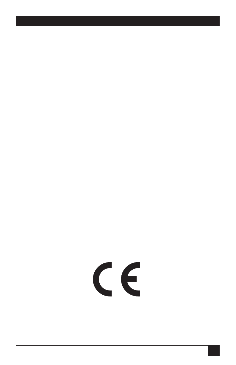
3. Install the Viewer program on a PC on your network:
The Ultra Remote comes with two software-installation diskettes.
• Insert the setup diskette in a PC running a recent version of a Microsoft
®
Windows®operating system and run the “setup” program on that diskette.
You’ll be guided through a standard Windows style installation process, as
shown in Figure 1-3.
• Click through to specify the installation directory and whether you want the
associated Start-menu folder, desktop, and quick-launch icons.
• Read the readme file on the diskette for late-breaking developments.
Figure 1-3. The setup wizard for the Ultra Remote’s Viewer.
Page 14
13
CHAPTER 1: Quick Start Guide
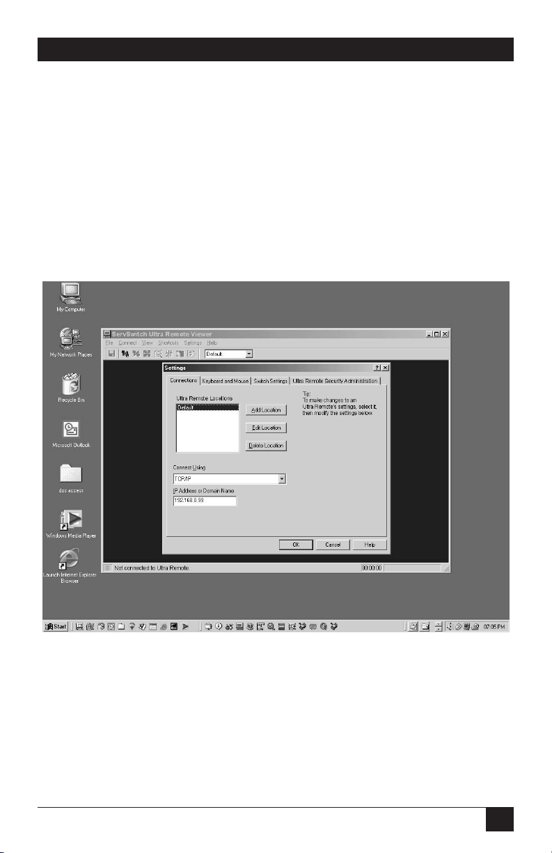
4. Configure the Viewer with the Ultra Remote’s IP address:
• Run the Ultra Remote Viewer program.
• Go to the Settings: Connections tab and use Edit Location to modify “Default”
to a name of your choosing, as shown in Figure 1-4.
• Change the IP address to the one you gave the Ultra Remote in step 2.
• Click OK. The new location name appears on the Ultra Remote toolbar.
• Click Help if you want to know more about the Viewer, or proceed with step 5
to make a connection.
Figure 1-4. Changing the default name in the Ultra Remote’s Viewer.
Page 15

14
SERVSWITCH™ ULTRA REMOTE
5. Make a connection:
• Press the connect icon (second from the left in the Viewer’s toolbar) or click
on “Connect” in the pulldown Connect menu. A logon box should appear.
• Enter the user ID “admin” and no password. After a moment you should see
the video output of the computer or KVM switch attached to the Ultra
Remote, as shown in Figure 1-5.
• The pass-through message box should appear. Click OK to forward your local
keyboard and mouse input to the remote computer or switch.
• Press [Ctrl][Alt][P] to exit the Viewer from pass-through mode or if you need
to move the mouse rapidly.
• Don’t forget to go to the Settings: Security tab to change the user ID and
password from its non-secure default value.
Refer to the remainder of this manual or the Viewer’s help files for more
information.
Figure 1-5. Remote video displayed in the Ultra Remote’s Viewer.
Page 16

15
CHAPTER 2: Specifications
2. Specifications
Hardware
Required — Monitor that supports your computers’ highest video
standard; in multiplatform applications, should be a
multisync model
Compliance — CE (EN55022 Class B, EN50082-1/EN60555-2, Low Voltage
Directive), FCC Part 15 Subpart B Class A, IC Class/
classe A, UL
®
, cUL, TÜV, VCCI
Standards — VGA, SVGA, or XGA video from directly attached computer;
Mac
®
, Sun, RS/6000®, or SGI™ video can be displayed if the
computers outputting these standards are attached to the
Ultra Remote through a KVM switch
Interfaces — To KVM switch or CPU: Proprietary composite of IBM PS/2
keyboard and mouse and VGA, SVGA, or XGA video;
Network: 10/100BASE-T Ethernet;
VGA IN/OUT and to monitor: VGA, SVGA, or XGA video;
To keyboard and mouse: IBM PS/2 type;
RS-232 port (nonfunctional): EIA/TIA RS-232 pinned
according to TIA-574, DTE;
USB (nonfunctional): USB Type A
Resolution and
Refresh Rate— Up to 1280 x 1024 noninterlaced at up to 76 Hz
Video Bandwidth — 150 MHz
Maximum
Distance — No distance limit to users connected through TCP/IP;
328 ft. (100 m) of LAN cable to directly attached hub,
router, network switch, or other LAN device;
20 ft. (6.1 m) of VGA or PS/2 cabling to any directly
attached monitor, keyboard, or mouse;
20 ft. (6.1 m) of original Serv cable to any directly attached
CPU or KVM switch;
20 ft. (6.1 m) of coaxial cable
—possibly as much as 100 ft.
(30.5 m), depending on the CPU or switch—to any
directly attached CPU or KVM switch
Page 17

16
SERVSWITCH™ ULTRA REMOTE
User Controls — Rear-mounted rocker switch for power;
Keyboard commands;
On-screen menus;
Viewer program installed on LAN PCs
Indicators — (4) Front-mounted LEDs:
POWER (receiving AC power),
REMOTE (TCP/IP user is logged in),
SERIAL (reserved for future use),
LOCAL (local user is logged in);
(2) Rear-mounted LEDs (unlabeled) next to network port:
10/100 (top) for network data rate;
ACTIVITY (bottom) for network-port activity;
Various indications and warnings in Viewer software
Connectors — All rear-mounted;
(1) DB25 female: KVM switch or CPU;
(1) RJ-45 female: Ethernet;
(3) HD15 female: Monitor, VGA in, VGA out;
(2) 6-pin mini-DIN female: PS/2 keyboard and mouse;
(2) DB9 male: Reserved for future use;
(2) USB Type A female: Reserved for future use;
(1) Power inlet: IEC 320 male;
Maximum
Altitude— 10,000 ft. (3048 m)
Temperature
Tolerance— 32 to 113˚F (0 to 45˚C)
Humidity
Tolerance— 5 to 80% noncondensing
Enclosure — Electrogalvanized steel
Page 18

17
CHAPTER 2: Specifications
Power — 115 to 230 VAC at 50 or 60 Hz, 750 mA, from AC outlet
through included power cord and IEC 320 male inlet to
UL, CUL, TÜV, and VCCI approved internal transformer
Size — 1.75"H (1U) x 16.7"W x 7"D (4.4 x 42.4 x 17.8 cm)
Weight — 8 lb. (3.6 kg)
Page 19

18
SERVSWITCH™ ULTRA REMOTE
3. Introduction
3.1 Overview
The ServSwitch™ Ultra Remote is a powerful product that extends the range of
access to your computers to anywhere in the world. Its advanced design makes it
compatible with most IBM
®
PC compatible computers and with industry-standard
KVM switches. It is most commonly used to extend a KVM switch’s user port to be
accessed through a LAN connection (or, in the future, a dialup/WAN connection).
First connect the Ultra Remote to a standalone computer or KVM switch and
your Ethernet network. Then assign an IP address to the Ultra Remote and run the
remote-access client from any workstation. You can then access the server just like
you were standing in front of it, but you can be at home, work, or halfway around
the world. Easy-to-configure security features prevent unauthorized access.
The Ultra Remote has a sophisticated scaling feature that allows you to position
output video images of any size image from your servers anywhere on your screen.
Now you can monitor servers while you work on other tasks. The scaling feature is
also ideal for fast video updates over slow links because less data is sent.
Because the Ultra Remote is a fully embedded product with no hard drive or
complicated operating system, it’s highly reliable and available.
A maximum resolution of 1280 x 1024 is supported for access to standalone or
KVM-switched PCs as well as KVM-switched Apple
®
Macintosh®, Sun®, and other
high-resolution computers through a TCP/IP connection. The Ultra Remote also
features a local KVM port for direct access at the unit’s location.
3.2 Features in Brief
• Connect to remote computers over Ethernet or (in the future) dialup.
• Up to 1280 x 1024 resolution.
• 1U-high chassis.
• Easy to install: Just give it an IP address and run the remote client application.
• Compatible with many ServSwitch family KVM switches and other KVM
devices.
• Has a local KVM port to access computers at the Ultra Remote’s location.
Page 20

19
CHAPTER 3: Introduction
• Scaling of computer images reduces amount of data sent and permits fast
screen updates over slow links.
• Quad-screen mode allows you to see four servers on one screen.
• Front-panel LEDs show power and currently connected input port (either
network or local KVM, or serial with future firmware).
• Solid-state embedded unit has no disk drive for maximum reliability.
• Remote client application is simple to use, installs very easily, and requires no
licensing.
• Password security prevents unauthorized configuration.
3.3 Features in Detail
Installation
The ServSwitch Ultra Remote is easy to install. Just connect it to your standard
10/100 Ethernet network, a keyboard, monitor, and mouse, and a KVM switch or
standalone computer. An IP address is assigned from a simple menu at the local
KVM port on the Ultra Remote. That completes the basic Ultra Remote
installation. Now go to a PC on the network and run the Viewer program provided
with the Ultra Remote. Enter the IP address of the Ultra Remote and hit the
connect icon. You are now prompted for a password. Enter the correct password
and you will be connected to the switch or standalone computer as if you were
directly connected by a single stretch of cable.
Operation
The Ultra Remote has three access points to the switch or standalone computer:
Ethernet, a local KVM port, and (not yet enabled) serial. The local KVM port is an
integrated switched analog port. When you connect the Ultra Remote to a KVM
switch, the integrated local KVM port allows you to have direct analog access to the
switch, so you don’t lose the KVM port on the switch. From the local KVM port,
you are able to configure the basic network and password information. All access to
the attached computers is through a menu. The menu prompts you to enter the
password. Once the correct password is entered, you are granted access if no one
else is connected. Otherwise, you are informed that another connection is in
progress and you are denied access. If you use the Administrator password, you can
override the connection in progress for immediate connection.
Page 21

20
SERVSWITCH™ ULTRA REMOTE
Server Windowing
You can choose the size of the window that you work with. This allows you to either
park a scaled image of your server in the corner of your screen or work with it at
full resolution. By resizing the Ultra Remote Viewer’s window, you automatically
communicate to the Ultra Remote, which then sends scaled video to fit your
resized window. When using a reduced window, less data is sent, improving
performance and reducing demands on network bandwidth. If you wish, you can
run in scaled, scrolled, or full-screen modes.
Security
The ServSwitch Ultra Remote is designed with the highest consideration for
security. For maximum security, the connection is encrypted with Blowfish or triple
DES. You can also program a timeout that will automatically terminate the session
when no keyboard or mouse activity is detected for a given length of time.
Quad-Screen Mode
You can view four servers at one time with the quad-screen mode. This integrated
high-performance feature is easy to set up and use. Simply select the servers that
you want to be viewed and enter quad-screen mode. All servers are viewed in real
time and are automatically scaled to fit their quadrant of the screen.
Color Modes and Resolution
The Ultra Remote hardware supports full 16-bit color. It can be programmed to
use black and white, grayscale, or color. This feature is excellent for slow links or
for reducing demands on network bandwidth.
Mouse Cursors
Competing products suffer from an annoying presence of two mouse cursors and
the requirement to synchronize the two cursors. The Ultra Remote uses one mouse
cursor in a very intuitive style to access the remote connection. Switching between
the remote servers and the applications on your own PC is smooth and effortless.
Video Resolution
Competing products make you adjust complicated controls to get the optimum
video quality. The Ultra Remote does it all automatically. It also supports up to
1280 x 1024 resolution at refresh rates up to 76 Hz.
Flash Memory
To support the latest devices and provide continuing features and support, the
ServSwitch Ultra Remote contains flash memory. We might occasionally release
firmware upgrades that you will be able to load into the Ultra Remote to add new
features or support new equipment. If and when we release such upgrades, our
technical-support technicians will be able to tell you how to download them; install
them with the “Flash Update” command (see Section 9.1).
Page 22

21
CHAPTER 3: Introduction
3.4 The Ultra Remote Illustrated
The front panel of the ServSwitch Ultra Remote looks like this:
The front-panel LEDs have these meanings when lit:
• POWER: The Ultra Remote is receiving AC power.
• REMOTE: A user is logged in through a TCP/IP (LAN) connection.
• SERIAL: Reserved for future use.
• LOCAL: A user is logged in through the local KVM connection.
The rear panel of the ServSwitch Ultra Remote looks like this:
The rear-panel connectors and LEDs have these functions/meanings:
• USB1, USB2 (USB Type As): Reserved for future use.
• COM1, COM2 (DB9s): Reserved for future use.
• KEYBOARD (left-hand 6-pin mini-DIN): Plug in a local PS/2
®
keyboard here.
• MOUSE (right-hand 6-pin mini-DIN): Plug in a local PS/2 mouse here.
• MONITOR (HD15 at top right): If you’re using the local port on a permanent
basis, plug in a local monitor here.
• VGA-IN (HD15 at top left): If you’re using the local port on a permanent
basis, plug in the included loop cable here (see Chapter 5).
• VGA-OUT (bottom HD15): If you’re using the local port on a permanent
basis, plug in the included loop cable here (see Chapter 5). If you’re only
using the local port temporarily until you can configure the Ultra Remote,
plug in a local monitor here.
• SWITCH/CPU (DB25): Run one of the included cables from this port to the
user port of a KVM switch or to the video, keyboard, and mouse ports of a
standalone computer.
Page 23

22
SERVSWITCH™ ULTRA REMOTE
• NETWORK (RJ-45): Plug a LAN cable (not included) into this connector. The
LEDs to its left work this way:
– 10/100 (top) is lit if the LAN data rate is 100 Mbps, dark if the data rate is
10 Mbps.
– ACTIVITY (bottom) is lit if the Ultra Remote is passing any packets to or
from the LAN.
• POWER (IEC 320): Plug in the included power cord here. (The internal
power supply is 115- or 230-VAC, 50 to 60 Hz, autosensing.)
Page 24

23
CHAPTER 4: Getting Started
4. Getting Started
4.1 The Complete Package
At the time of this writing, the ServSwitch™ Ultra Remote package consists of:
• (1) Ultra Remote.
• (1) 6-ft. (1.8-m) power cord.
• (1) 5-ft. (1.5-m) DB25 male to DB25 male ServSwitch-to-ServSwitch Expansion
Cable for attaching a compatible KVM switch.
• (1) 5-ft. (1.5-m) DB25 male to HD15 male and dual 6-pin mini-DIN male
ServSwitch CPU Cable for attaching a standalone computer.
• (1) 1-ft. (0.3-m) HD15 male to HD15 male video-loop cable used to enable
permanent local-monitor attachment.
• (2) 3.5" diskettes containing Ultra Remote Viewer software.
• (1) Pair of brackets that can be used to mount the Ultra Remote in a 19" rack
(see the Appendix) and (4) screws to secure the brackets to the Ultra Remote.
• This manual.
4.2 Other Things You Will Need
You will also need these items to connect and use your Ultra Remote:
• (1) Standalone computer or KVM switch to be viewed and accessed.
• (1) Local PC keyboard with PS/2 connector.
• Optionally, (1) local PS/2 mouse.
• (1) Local VGA monitor.
• An active Ethernet TCP/IP network
• (1) Network cable with an RJ-45 male connector at the Ultra Remote end.
• At least (1) PC on the network on which the Ultra Remote’s Viewer software
can be loaded.
Page 25

24
SERVSWITCH™ ULTRA REMOTE
5. Hardware Installation
NOTE
This product is not intended for connection to circuits carrying
telecommunication-network voltages (TNV).
If you want to do so, you can permanently connect a local keyboard/video/mouse
user station to the ServSwitch™ Ultra Remote as shown in Figure 5-1. A user at this
station will be able to access the switch or computer CPU directly attached to the
Ultra Remote using the connect login that will be described in Section 6.3.
Figure 5-1. Installing the Ultra Remote with a local user station
permanently attached for CPU and KVM-switch access.
If you don’t need a permanent local user station, you will still need to
temporarily connect a local monitor, keyboard, and (optionally) mouse to the
Ultra Remote, as shown in Figure 5-2, long enough to view the Ultra Remote’s
power-up progress and then configure its IP address. When the local monitor is
connected this way, you will not see anything on its screen until the Ultra Remote
completes its power-on process (about 25 seconds).
KEYBOARD
VIDEO-
LOOP
CABLE
MOUSE
MONITOR
SWITCH/CPU
NETWORK
Page 26

25
CHAPTER 5: Hardware Installation
Figure 5-2. Installing the Ultra Remote with a local user station temporarily
attached for power-up observation and configuration.
Take these steps to install the Ultra Remote’s hardware and cabling:
CAUTION!
The only types of devices you can attach directly to the Ultra Remote
are IBM PC compatible computers and KVM switches. If the KVM switch
is a multiplatform model, you can attach Mac, Sun, and/or other non-PC
types of computers to the switch. However, unless the KVM switch is
hardware-compatible with the Ultra Remote—that is, unless it has a
DB25 user port pinned the same way as the Ultra Remote’s
SWITCH/CPU port, like the regular ServSwitch™ does—the KVM switch
must be able to translate the non-PC data to and from VGA-compatible
video signals and PS/2 compatible keyboard and mouse signals.
Similarly, don’t swap in other types of cables for the CPU cable or
KVM-switch cable that came with the Ultra Remote. You will not be able
to attach an Apple computer or a Sun only KVM switch directly to the
Ultra Remote by using a Mac or Sun style CPU cable.
1. Either place the ServSwitch Ultra Remote on a stable, clean, dry, flat surface
or use the included rackmount brackets to mount it in a 19" rack as described
in the Appendix.
2. Run the included power cord from the Ultra Remote’s IEC 320 male power
inlet to a working AC outlet.
3A. If you’re attaching a standalone computer CPU or a KVM switch whose user ports have
individual video, keyboard, and mouse connectors, run the included three-to-one
ServSwitch CPU Cable from the Ultra Remote’s DB25 female SWITCH/CPU
port to the video, keyboard, and (if you want) mouse ports or user-port
connectors on the CPU or KVM switch.
KEYBOARD
MOUSE
MONITOR
SWITCH/CPU
NETWORK
Page 27

26
SERVSWITCH™ ULTRA REMOTE
3B. If you’re attaching a compatible KVM switch with an identically pinned DB25 female
user port, run the included ServSwitch-to-ServSwitch Cable from the Ultra
Remote’s DB25 female SWITCH/CPU port to the DB25 female “USER,”
“KVM,” or “MKM” composite-output port on the KVM switch.
3C. If you’re attaching a KVM switch with a single user port of some other type, attach the
included three-to-one ServSwitch CPU Cable to the Ultra Remote’s DB25
female SWITCH/CPU port. Attach a user cable designed for the KVM switch
to the KVM switch’s user port. Mate the matching connectors on the two
cables.
4.
Run the included LAN cable from the Ultra Remote’s RJ-45 female NETWORK
port to your hub, router, network switch, or other Ethernet device.
5. Plug a local PS/2 keyboard and mouse into the Ultra Remote's 6-pin miniDIN KEYBOARD (left) and MOUSE (right) ports.
6A. If you’re attaching your local user-station equipment temporarily, plug a local
monitor into the Ultra Remote’s HD15 female VGA-OUT port (the HD15 in
the bottom row of connectors).
6B. If you’re attaching your local user-station equipment permanently, plug a local
monitor into the Ultra Remote’s HD15 female MONITOR port (top row of
connectors, right). Then run the included video-loop cable between the Ultra
Remote’s HD15 female VGA-OUT (bottom row) and VGA-IN (top row, left)
ports.
NOTE
At the time of this writing, the Ultra Remote’s RS-232 (DB9) and USB
ports don’t work; don’t connect anything to them. They are reserved for
future use and might be enabled by future versions of the Ultra
Remote’s firmware.
Page 28

27
CHAPTER 6: Initial Power-Up and Configuration
6. Initial Power-Up and
Configuration
6.1 Powering Up the Ultra Remote
If you haven’t already done so, run the ServSwitch™ Ultra Remote’s power cord
from the Ultra Remote’s power inlet to a working AC outlet. Move the rocker
switch on the Ultra Remote’s rear panel to the “|” position to turn the unit on. If
the green POWER LED on the front panel doesn’t light, turn the unit back off,
make sure your outlet is providing power, and wait at least 15 seconds before
turning power on again.
After the Ultra Remote completes a self-test and startup sequence, it displays the
connect-login screen, as shown in Figure 6-1. If you have used the video-loop cable
in a permanent local user-station installation (see Chapter 5), your monitor might
remain blank for up to 25 seconds before a login screen appears.
If no login screen appears, check the cable connections as shown in Chapter 5.
Figure 6-1. The connect-login screen.
Page 29

28
SERVSWITCH™ ULTRA REMOTE
6.2 About Logins
A default administrator account exists for initial configuration when the Ultra
Remote first starts up. The user ID is “admin” (not case sensitive) and there is no
password.
CAUTION!
One of the first steps an administrator should perform is to secure the
user ID and password for the default administrator account. Change
them with the Ultra Remote Viewer using the default account and the
Settings:Security tab (see Section 10.2.4). If you forget the administrator
user ID or password, override the user ID and password check as
described in Section 6.7.
There are two types of logins:
• Connect login: Connects the local user station to the attached KVM switch or
CPU.
• Configure login: Authorizes the user to configure the Ultra Remote’s IP
address.
Press the [F9] key to display the connect-login screen or the [F10] key to display
the configure-login screen. Each screen is a different color. You must use the
administrator user ID for the configure login.
You may press the [F1] key to view help text on a login screen. Press [F1] again
to remove the help text from the screen.
Page 30

29
CHAPTER 6: Initial Power-Up and Configuration
6.3 Using the Connect Login for the First Time
Take these steps to verify your cable installation and to access the KVM switch or
CPU attached to the Ultra Remote from the local user station:
1. Press [F9] to display the green connect-login screen.
2. Login at the connect-login screen using “admin” as the user name (not case
sensitive) and no password.
3. Verify that the video is OK and the keyboard and mouse perform properly.
4. Press [Ctrl], [Alt], and the [L] key simultaneously to exit the connect login.
(Press this key combination whenever you need to exit the connect-login
screen.)
If you do not see the video of the connected device or see an invalid mode screen
like the one shown in Figure 6-2, check the cable connections (see Chapter 5).
Figure 6-2. The invalid-mode screen.
Page 31

30
SERVSWITCH™ ULTRA REMOTE
6.4 Using the Configure Login for the First Time
You only need to set a few basic communication parameters in the Ultra Remote to
make it accessible to the Ultra Remote Viewer program you’ll install later.
Administrators can configure other settings, such as user management and
security, from the Viewer.
To configure the Ultra Remote for remote login through the Ultra Remote
Viewer program, give it a TCP/IP address as follows:
1. Press [F10] to display the gray configure-login screen (shown in Figure 6-3).
2. Login at the configure-login screen using “admin” as the user name (not casesensitive) and no password. The configure screen should appear (see
Section 6.5).
3. Enter the IP address, subnet mask, optional gateway address, TCP port (if
you’re using something other than 5678), and speed/duplex (if you’ve
connected the Ultra Remote to a LAN device that requires a particular data
rate or duplex setting).
4. Press [F10] to save the configuration data and return to the connect-login
screen. The changes take effect immediately.
Figure 6-3. The configure-login screen.
Page 32

31
CHAPTER 6: Initial Power-Up and Configuration
6.5 The Configure Screen
After you login at the configure-login screen (see Section 6.4), the configure
screen should appear, as shown in Figure 6-4. Move between fields on the
configure screen by pressing the up- and down-arrow keys. As you move from one
field to another, values are validated. If you enter an invalid value, the arrow keys
do not function until you either correct the value or press the [Esc] key. If you
press the [Esc] key, the original value is restored in the field. Edit within a field by
using left- and right-arrow keys, the [Del] key, and the backspace key.
Figure 6-4. The configure screen.
IP address
The Ultra Remote uses a fixed IP address. Change the default address to permit
remote access by the Ultra Remote’s Viewer program. Enter a valid IP address in
the standard dotted-decimal format (for example, 192.168.1.71).
Subnet mask
Enter a valid subnet mask in the subnet mask field (for example, 255.255.255.0).
The Ultra Remote does not apply an invalid subnet mask; it reverts to the last
known good subnet mask instead.
Gateway (optional)
If necessary, enter a gateway address to allow access to the Ultra Remote from
networks other than the one defined by the IP address and subnet mask. Enter a
valid IP address in the standard dotted-decimal format (for example, 192.168.1.1).
Page 33

32
SERVSWITCH™ ULTRA REMOTE
TCP port (optional)
The Ultra Remote uses TCP port 5678 by default. If you want to use a different port,
enter a valid port number of up to four decimal digits here; you must also change
the TCP-port setting in each copy of the Viewer program (see Section 10.1). This
change doesn’t take effect until the Ultra Remote is powered off and back on.
Speed/duplex (optional)
By default, the Ultra Remote is set to “Auto,” meaning it autosenses and
autoadjusts to the best available data rate (10 or 100 Mbps) and duplex setting
(half- or full-duplex) on its network port. But if you’ve connected the network port
to a device that doesn’t negotiate and requires a certain speed or duplex setting,
use [PgUp] and [PgDn] (the page-up and page-down keys) to page from “Auto” to
“100MB full,” “100MB half,” “10MB full,” or “10MB half.” This change doesn’t take
effect until the Ultra Remote is powered off and back on.
Saving or abandoning changes
Press the [F10] key to apply network settings immediately and to make the Ultra
Remote available to copies of the Viewer program you’ll install on the network.
Press [F9] to cancel the changes. After saving or canceling your changes, the
connect-login screen is displayed. To change the settings, login again at the
configure-login screen.
6.6 Connect Contention
The ServSwitch Ultra Remote doesn’t allow the local user and a Viewer user to
connect at the same time. If you login as an administrator at the local user station,
and a regular Viewer user is connected, the Ultra Remote sends a message to the
Viewer indicating that an administrator has logged in and then disconnects the
Viewer. As a security precaution, you must login twice at the local user station: once
to disconnect any existing Viewer connections, and then again to establish your
own connection. If you login at the local user station with a non-administrator
account, the connect login fails and the remote connection is unaffected.
6.7 Password Defeat
If you forget the administrator’s user ID or password, remove the cover of the Ultra
Remote’s enclosure and place a jumper on the pins labeled “PASSWORD
DEFEAT.” (Do not remove the cover for other reasons unless directed to do so by a
Black Box technician.) When this jumper is in place, a connect login or configure
login succeeds with any user ID and password and the login will be as an
administrator. Once logged in, set a new administrator user ID and password, then
remove this jumper. A reminder that the PASSWORD DEFEAT jumper is place will
be displayed on the Ultra Remote’s login screens (including when a Viewer logs
in) until the jumper is removed.
Page 34

33
CHAPTER 7: Installing the Ultra Remote’s Viewer Software
7. Installing the Ultra Remote’s
Viewer Software
7.1 Requirements
The ServSwitch™ Ultra Remote’s Viewer program runs on most Microsoft
®
Windows®based PCs. The minimum hardware and software requirements for such
a PC are:
• 133-MHz IBM compatible PC with 32 MB of system memory and 4 MB of free
disk space.
• VGA display adapter and monitor, capable of 640 x 480 resolution.
• Keyboard and mouse.
• Network connection with TCP/IP protocol.
• Microsoft Windows 95 or more recent Windows operating system.
Page 35

34
SERVSWITCH™ ULTRA REMOTE
7.2 Installing the Viewer with the Setup Wizard
The Setup Wizard guides you through installation of the Ultra Remote Viewer.
Look for the setup file on the diskettes included with the Ultra Remote. (If the
setup file or Viewer doesn’t run correctly on your machine, you might need to
download a more recent version of the Viewer, if one exists; if it does, our
technical-support technicians will be able to tell you how to get it.)
Assuming your floppy drive uses the drive letter “a:”, to install the Viewer by
running setup from the diskette, click on Start, drag the cursor to Run, and type in
“a:/setup”. The Setup Wizard will appear:
Figure 7-1. The Setup Wizard.
During the installation process, you may choose the folder in which you install
the Viewer. When the installation is complete, you can start the Viewer using one
of the items optionally created by the Setup Wizard: its desktop icon, its Quick
Launch icon, or its Windows Start Menu entry.
Page 36

35
CHAPTER 7: Installing the Ultra Remote’s Viewer Software
7.3 Using the Viewer for the First Time
Keep the Viewer’s two modes in mind as you prepare to use it:
• Pass-through mode takes control of your keyboard and mouse away from your
computer and passes it to a remote computer attached to the Ultra Remote.
To regain control of your computer’s keyboard and mouse, hold down the
[Ctrl], [Alt], and [P] keys simultaneously. You may also use mouse escape
movements defined in the Settings:Keyboard and Mouse tab (see
Section 10.2.2) to exit pass-through mode.
• Full-screen mode takes control of your monitor and uses the whole screen to
display a remote computer’s screen. To regain control of your monitor, hold
down the [Ctrl], [Alt], and [F] keys simultaneously. Exiting pass-through
mode also returns control from full-screen mode.
When you run the Viewer for the first time, take these steps:
1. Connect: Click the Connect icon in toolbar of the Ultra Remote Viewer and
wait for the login box to appear.
2. Login: Login with the default administrator account (user name “admin”—
not case sensitive—and no password). After a moment, you should see the
video of the KVM switch or CPU attached to the Ultra Remote. When the
pass-through warning message appears, click the OK button to forward your
local keyboard and mouse to the remote computer. If you are prompted with
the full-screen warning message, click the Cancel button.
3. Perform administrative tasks: If you are an administrator, you may change
your account’s user ID and password at this time. Other administrative tasks
you might want to do (describedin Sections 10.2.3 through 10.2.5) are:
– Add user IDs and passwords (important!).
– Specify the type of encryption between the Ultra Remote and Viewer
stations.
– Set an inactivity-disconnection timeout for Viewer stations.
– Enable KVM-switch features in the Viewer.
Page 37

36
SERVSWITCH™ ULTRA REMOTE
8. The Viewer Screen
This chapter discusses these elements of the ServSwitch™ Ultra Remote’s Viewer
screen:
• Title bar
• Menu commands
• Toolbar
• Display area
• Status bar
• Windows buttons
• Question-mark help
8.1 The Title Bar
When the Viewer is not connected to an Ultra Remote, the title bar displays the
name of the program, “ServSwitch Ultra Remote Viewer.” When a connection is
active, the Viewer also displays its name (defined in the Connections dialog box) in
the title bar.
Figure 8-1. The title bar (displays an Ultra Remote location).
8.2 Menu Commands
Menus, positioned below the title bar, list commands and options for operating the
Viewer.
Figure 8-2. The menu commands.
Page 38

37
CHAPTER 8: The Viewer Screen
8.3 The Toolbar
Figure 8-3. The toolbar, including icons and the
remote-computer selection listbox.
Toolbar icons: The toolbar provides quick access to these icon-triggered functions:
Save bitmap
Connect
Disconnect
Full-screen
Autosize
Quad-screen
Ctrl + Alt + Delete
Refresh
Ultra Remote location list: When the Viewer is not connected, a listbox of Ultra
Remote locations is visible. When you select a named Ultra Remote in the listbox,
you may connect to that Ultra Remote by clicking on the Connect toolbar icon.
After connection, the listbox disappears.
Remote-computer selection list: When you connect to an Ultra Remote with an
attached KVM switch, a remote-computer selection list replaces the Ultra Remote
location list. Select a computer in the remote-computer selection list in order to
switch your keyboard, monitor, and mouse to that computer.
Page 39

38
SERVSWITCH™ ULTRA REMOTE
8.4 The Display Area
The display area contains a real-time image of the video being output by one or
more remote computers. In quad-screen view, the display area contains images
from up to four remote computers. The Viewer may scale images to fit into the
display area or display images at the same resolution as the remote computer is
outputting them. View-menu commands control the appearance of images in the
display area.
8.5 The Status Bar
The status bar, at the bottom of the Viewer window, contains the following items:
• A virtual pass-through LED indicator to indicate whether your video, keyboard,
and mouse are connected to a remote computer.
• Text describing a current menu selection or how to exit pass-through mode.
• A connection timer.
• A description of the video resolution displayed in the display area.
Figure 8-4. The status bar.
8.6 The Windows Buttons
Minimize: This button shrinks the Viewer screen to the size of an icon in the
Windows taskbar. If you are logged in, the Ultra Remote continues to
refresh the display area’s view, even though it is not visible.
Maximize: This button allows the Viewer to cover the entire screen. This
differs from full-screen mode in that the title bar, menus, toolbar, and status
bar are all visible.
Exit: This button disconnects the Viewer from any Ultra Remote it’s
connected to and terminates the Viewer application.
Page 40

39
CHAPTER 8: The Viewer Screen
8.7 Question-Mark Help
On some dialogs, there will be a small question mark in the upper right-hand
corner. Click on the question mark, and then click on a field in the dialog to get
help on that specific item.
Figure 8-5. Question-mark help (icon at right).
Page 41

40
SERVSWITCH™ ULTRA REMOTE
9. The Viewer’s Menu Commands
This chapter discusses the commands available through the menu system of the
ServSwitch™ Ultra Remote’s Viewer program.
NOTE
The mouse is normally used to select menus and options in the Viewer,
but you can also use your keyboard. Each of the menu headers has an
underlined letter in its name; press the [Alt] key and that letter key
simultaneously to bring up that menu. Similarly, the options in each
menu have underlined letters in their names whose keys you can press
by themselves to select those options when the menu is open.
9.1 The File Menu
The File menu contains the “Flash Update,” “Save Bitmap,” and “Exit” commands,
as shown in Figure 9-1.
Figure 9-1. The File menu.
Flash Update: This command—available to administrators only, grayed out for
others—allows the Viewer to update an Ultra Remote with new firmware. (The
command prompts for the name of a flash-update file. Flash-update filenames take
the form “ulpxxx.bin,” where xxx is a revision number. When an upload is finished,
the Ultra Remote breaks the connection with the Viewer and restarts to activate the
new firmware. Wait at least one minute before reconnecting to the Ultra Remote.
Save Bitmap: This command saves the image in the Viewer’s display area to a
Windows bitmap (.bmp) file. In quad-screen view, all four quadrants are saved to
the same bitmap file. The Viewer saves the display area only and not the title bar,
menus, toolbar, or status bar. This operation is available only when you are logged
in to an Ultra Remote.
Exit: This command quits out of the Viewer application. If the Viewer is logged in,
the Viewer exits pass-through mode and disconnects before closing.
Page 42

41
CHAPTER 9: The Viewer’s Menu Commands
9.2 The Connect Menu
The Connect menu contains the “Connect” and “Disconnect” commands, as shown
in Figure 9-2. Only one of these is available at a time; “Connect” is grayed out if a
connection already exists, and “Disconnect” is grayed out if no connection exists.
See Chapter 11 for more information about these commands.
Figure 9-2. The Connect menu.
Connect: If you select this, the Viewer displays a list of all the Ultra Remote units it
has been configured to connect to. You may select any Ultra Remote on the menu
to initiate a connection.
Disconnect: If you select this, the Viewer disconnects from the Ultra Remote it’s
currently connected to.
Page 43

42
SERVSWITCH™ ULTRA REMOTE
9.3 The View Menu
View-menu commands control how the video image from the remote computer is
displayed. See Chapter 12 for more information about these commands.
Figure 9-3. The View menu.
Scrolled: In scrolled view, the remote computer’s video image displays in its native
resolution, providing the sharpest image. If the Viewer’s display area is not large
enough to display the image horizontally or vertically, scroll bars appear so that
you can view any part of the image.
Scaled: In scaled view, the remote computer’s video image is squeezed or stretched
to fit in the display area. When you change the size of the display area, the image
changes to fit into the new size.
Page 44

43
CHAPTER 9: The Viewer’s Menu Commands
Don’t Enlarge [IMPORTANT]: At times, you may prefer to keep your window size
constant and inhibit the Viewer from enlarging the display area. This is particularly
true when switching between remote computers on a KVM switch. If you select the
Don’t Enlarge option, images larger than the display area are scaled and images
smaller than the display area are centered.
Auto Size: This option performs an Auto Size Now command (see below) when the
Viewer displays a new video resolution in the display area.
Single: Single-screen view, as opposed to quad-screen view, is the default display
view. The Viewer enters single-screen view when you log into an Ultra Remote. In
single-screen view, the video image from only one remote computer is shown in
the display area. If the Ultra Remote is not connected to a KVM switch, the display
area shows the image of the remote computer connected to the Ultra Remote.
Quad: Quad-screen view is not available unless the Ultra Remote is attached to a
compatible KVM switch. The Viewer displays video from up to four remote
computers at the same time by controlling the KVM switch. In quad-screen view,
mouse and keyboard input does not connect to any of the four remote computers,
and pass-through mode is disabled. The Viewer divides the display area into four
quadrants and a computer-selection box for each quadrant of the screen appears
on the toolbar.
Color: The image is displayed in color. See also Section 12.4.
Gray: The image is displayed in 256 shades of gray.
Black and White: The image is displayed in black and white only.
Toolbar and Status Bar: You may select that the toolbar and/or status bar not be
displayed, providing more viewing space at the cost of convenience.
Auto Size Now: When you select this, the Viewer attempts to size a remote
computer’s image in the display area using the best possible resolution. If the
remote image is smaller than the display area, the image appears centered in the
display area. If the image is larger than the display area, the Viewer increases the
window size to display the image at the remote computer’s resolution. However, if
the image too large to be viewed on your computer, the Viewer maximizes to fill
your screen. If the remote computer’s resolution is the same as your computer’s,
Auto Size maximizes the window to fill your screen. You may also select the Auto
Size Now command using the toolbar icon.
Page 45

44
SERVSWITCH™ ULTRA REMOTE
Full Screen: In full-screen mode, the Viewer’s display area takes over the entire
screen area of your computer. The title bar, menus, toolbars, and status bar of the
Viewer are not displayed – only the video image from the remote computer is
visible on the screen.
A message dialog displays a warning when you enter full-screen view. The
message gives a brief description of full-screen view and how to exit it. A checkbox
at the bottom of the message dialog allows you to suppress the display of that
dialog.
Refresh: This command, which can also be invoked with a button on the toolbar,
causes the Ultra Remote to resend the current screen image.
Pass Through: This command causes the Viewer to enter pass-through mode (see
Section 11.3).
Page 46

45
CHAPTER 9: The Viewer’s Menu Commands
9.4 The Shortcuts Menu
As a convenience, the Shortcuts menu (shown in Figure 9-4) provides methods to:
• Issue the Windows operating-system keyboard functions [Alt]+[Tab] and
[Ctrl]+[Alt]+[Delete] to the remote computer immediately.
• Direct certain “system keys” to your computer or to the remote computer while
you are in pass-through mode.
• Turn hotkeys and mouse escape movements on or off.
Figure 9-4. The Shortcuts menu.
Issue Remote Alt+TAB: Send the [Alt] and [Tab] keys to the remote computer as
if they were pressed simultaneously.
Issue Remote Ctrl+Alt+Del: Send the [Ctrl], [Alt], and [Del] keys to the remote
computer as if they were pressed simultaneously.
System Keys Remote and System Keys Local: Send system keys (see Section 11.3.4)
to the remote computer or to your computer.
Shortcuts To Exit Pass-through: See Section 11.3 for information about pass-
through mode, and Section 10.2 for information about hotkeys and mouse escape
movements. At least one of the following shortcuts must be active or it would be
impossible to get out of pass-through mode. If you attempt to deactivate all three
methods, the Viewer automatically enables the hotkey (keystrokes) shortcut.
• Hotkey To Exit Pass-through
• Fast Mouse To Exit Pass-through
• Slow Mouse To Exit Pass-through
Page 47

46
SERVSWITCH™ ULTRA REMOTE
9.5 The Settings Menu
The commands in the Settings menu (shown in Figure 9-5) bring up a tabbed
dialog box that you can use to configure both the Ultra Remote and the Ultra
Remote’s Viewer. Except for basic communications settings, the Ultra Remote is
configured from the Viewer using the “KVM Switch” and “Security” tabs. The
Viewer is configured using the “Connections” and “Keyboard and Mouse” tabs. See
Chapter 10 for a full description of each tab in the Settings dialog box.
Figure 9-5. The Settings menu.
Connections: This tab allows you to maintain a list of Ultra Remote locations to
which the Viewer may connect.
Keyboard and Mouse: This tab defines special key sequences and mouse escape
movements to exit pass-through mode on the Viewer.
KVM Switch: This tab maintains names associated with KVM-switch ports and
keyboard commands used to switch to those ports. Ultra Remote KVM-switch
settings are managed from the Viewer by an administrator. If the Viewer is not
logged in to an administrator account, the KVM Switch tab can be selected, but will
be empty.
Security: Ultra Remote security settings are managed from the Viewer by an
administrator. If the Viewer is not logged in to an administrator account, the
Security tab can be selected, but will be empty.
Page 48

47
CHAPTER 9: The Viewer’s Menu Commands
9.6 The Help Menu
Help is available in various forms through the Help menu (shown in Figure 9-6).
Figure 9-6. The Help menu.
Help Topics: This command invokes full online help.
Ultra Remote Web Support: This menu option opens a browser and links to the
Black Box Web site.
Full Screen Warning: Enable or disable the warning dialog that appears before the
Viewer switches to full-screen mode.
Pass Through Warning: Enable or disable the warning dialog that appears before
the Viewer switches to pass-through mode.
About Ultra Remote: Brings up a box that gives information about the current
revision levels of the Viewer and the last (most recent) Ultra Remote it was
connected to, as shown in Figure 9-7.
Figure 9-7. The About box.
Page 49

48
SERVSWITCH™ ULTRA REMOTE
10. Configuration Settings
The commands in the Settings menu of the ServSwitch™ Ultra Remote’s Viewer
program bring up a tabbed dialog box that you can use to configure both the Ultra
Remote and the Ultra Remote Viewer. You can configure the Viewer with the
“Connections” and “Keyboard and Mouse” tabs; these configuration settings are
stored on your computer. If you are an administrator, you may also configure the
Ultra Remote using the “KVM Switch” and “Security” tabs; these settings are stored
on the Ultra Remote.
These buttons appear at the bottom of the tabbed dialog box and, if selected,
remove the Settings dialog box from view:
OK: This button applies changes made in all tabs except the Security tab to the
Viewer immediately. If an administrator changes items in the Security tabs, the
changes are saved on the Ultra Remote and the changes become effective at the
next login.
The Viewer disables the OK button (grays it out) if another configuration dialog
box, such as the User Details dialog box of the Security tab, is open. Close the
other dialog box to re-enable the OK button.
Cancel: This button discards changes you make in all tabs.
10.1 Connections
The Connections tab, shown in Figure 10-1 on the next page, displays and
maintains a list of Ultra Remote locations to which the Viewer may connect. A
location is a name you assign to a given Ultra Remote.
Ultra Remote Locations: Three items describe each Ultra Remote location in the
list: location name, connection type, and address. When you select a location in the
list, the Viewer displays corresponding parameters in the Connect Using and IP
Address fields. You may add, rename, or remove a location using the Add
Location, Edit Location, and Delete Location buttons respectively. Changes made
here in the Connections tab are immediately reflected in the Connect menu and
in the remote-computer selection list on the toolbar.
The Add, Edit, and Delete Location buttons bring up another dialog box that
displays the location currently selected in the toolbar’s remote-computer selection
listbox. That location may not be edited or deleted if the Viewer is connected to it.
The location selected in the Locations list when you close the dialog box is also
automatically selected in the toolbar’s remote-computer selection listbox.
Page 50

49
CHAPTER 10: Configuration Settings
Add Location: This button defines a new location to be added to the list of Ultra
Remote locations. A dialog box is opened where the name of the new location can
be specified. After you add the location, it is automatically selected so that you can
define its parameters.
Edit Location: This button brings up a dialog box where you can change the name
of the location. Because the Ultra Remote locations list is sorted alphabetically by
name, renaming the location may change its position in the list.
Delete Location: This button removes the selected location from the list.
Connect Using: At this time, the only valid choice is TCP/IP. Other access methods
might be added in future versions of the firmware.
IP Address or Domain Name: This field specifies a domain name or a TCP/IP
address (and, optionally, TCP port) of an Ultra Remote to which the Viewer may
connect. A TCP/IP address takes the standard form nnn.nnn.nnn.nnn(:port), while
you’d use the part of the domain name that would follow “http://”, such as
“ultraremote.mycompany.com.” The Ultra Remote uses port 5678 by default; if that
port is acceptable, you don’t need to specify it here. If you use a different TCP port,
it must match the TCP port configured for the Ultra Remote (see Section 6.5).
Figure 10-1. The Settings:Connections tab.
Page 51

50
SERVSWITCH™ ULTRA REMOTE
10.2 Keyboard and Mouse
The Keyboard and Mouse tab, shown in Figure 10-2, defines keyboard hotkeys and
mouse escape movements.
Figure 10-2. The Settings:Keyboard and Mouse tab.
10.2.1 H
OTKEYS
Hotkeys are keystrokes or combinations of keystrokes that a device interprets as a
command. With the Ultra Remote’s Viewer, single-keystroke hotkeys are used to:
• Enable or disable pass-through mode
• Enable or disable full-screen view
• Send [Ctrl]+[Alt]+[Del] to a remote computer
• Send [Alt]+[Tab] to a remote computer
You can send hotkeys to the Viewer in one of two ways: Simultaneously press the
left-[Ctrl] and [Alt] keys followed by the hotkey, or press and release the left-[Ctrl]
key and then press the hotkey within 2 seconds. The second option provides an
alternative in case the first option conflicts with an application on the remote
computer. For example, [Ctrl]+[Alt]+P is also a command in Microsoft Word
®
.
Note that the second option may conflict with function keys on a KVM switch.
Page 52

51
CHAPTER 10: Configuration Settings
You may choose any letter in the alphabet to represent a hotkey, as long as it is
not used as another hotkey.
Here are the elements in the “Hotkeys” area of the Settings:Keyboard and Mouse
tab:
Active: This checkbox enables the hotkey fields in the dialog box. If you clear both
the Fast Mouse Movement and Slow Mouse Movement checkboxes (see Section
10.2.2), the Viewer automatically checks the Active checkbox to prevent you from
disabling all methods of exiting pass-through mode.
Trigger: This list defines key sequences that cue the Viewer to expect a hotkey. The
options are “LCtrl+Alt,” “LCtrl-down LCtrl-up” (press and release left-[Ctrl]), and
“Both.” If you select left-[Ctrl]+[Alt], the Viewer will recognize a hotkey command
if you hold down left-[Ctrl], either [Alt] key, and the hotkey at the same time. If
you select left-[Ctrl]-down left-[Ctrl]-up, the Viewer will recognize a hotkey
command if you press and release the left-[Ctrl] key and then press and release the
hotkey. If you select Both, the Viewer will recognize a hotkey command if you use
either of these methods.
Alt+Tab: This hotkey sends an [Alt]+[Tab] key sequence to the remote computer
irrespective of whether the Viewer is in pass-through mode or not.
Ctrl+Alt+Del: This hotkey sends a [Ctrl]+[Alt]+[Del] key sequence to the remote
computer irrespective of whether the Viewer is in pass-through mode or not.
Toggle Pass-through Mode: This hotkey puts the Viewer into pass-through mode if
the Viewer is not already in pass-through mode and takes the Viewer out of passthrough mode if the Viewer was in pass-through mode.
Toggle Full Screen Mode: This hotkey puts the Viewer into full-screen view if the
Viewer is not already in Full Screen mode and takes the Viewer out of full-screen
view if the Viewer was in Full Screen mode.
Page 53

52
SERVSWITCH™ ULTRA REMOTE
10.2.2 M
OUSEESCAPEMOVEMENTS
In addition to hotkeys, you may also use two types of mouse escape movements to
exit pass-through mode. Mouse escape movements only take the Viewer out of passthrough mode; they do not put the Viewer in pass-through mode.
• “Fast mouse movement” is moving the mouse using continuous rapid zigzag
motions for several seconds.
• “Slow mouse movement” is a continuous long mouse movement in a single
direction.
Here are the elements in the “Mouse Escape Movements” area of the
Settings:Keyboard and Mouse tab:
Fast Mouse Movement: This checkbox, if enabled, allows you to escape passthrough mode using continuous rapid mouse movement.
Activating the check box also enables a slider control to the right of the
checkbox. The slider controls mouse sensitivity for fast mouse movement. Moving
the slider to the left reduces mouse sensitivity and makes it easier to escape passthrough mode. Moving the slider to the right increases the mouse sensitivity and
requires greater mouse movement to escape pass-through mode.
Slow Mouse Movement: This checkbox, if enabled, allows you to escape passthrough mode using a long mouse move in one direction.
Activating the check box also enables a slider control to the right of the
checkbox. The slider controls mouse sensitivity for Slow Mouse movement. Moving
the slider to the left reduces mouse sensitivity and requires moving the mouse a
smaller distance. Moving the slider to the right increases mouse sensitivity and
requires longer mouse movement.
Page 54

53
CHAPTER 10: Configuration Settings
10.2.3 KVM S
WITCH
An administrator may use the KVM Switch tab, shown in Figure 10-3, to perform
the following functions (see also Chapter 13):
• Activate the KVM-switch-only features of any Viewer that logs into the selected
Ultra Remote.
• Name KVM-switch ports to allow the names to appear in the toolbar’s remotecomputer selection list after a login.
Non-administrator users can select this tab, but it will be empty.
Figure 10-3. The Settings:KVM Switch tab.
Device: Use this listbox to specify the type of device you’re configuring. (This must
be a device attached to the currently selected Ultra Remote.) The device may be a
standalone PC, one of the supported KVM-switch models in the list, or a custom
KVM switch. Use “standalone PC” if the Ultra Remote connects to a PC. If you
select standalone PC, all KVM-switch-only features of the Viewer are disabled. If
you select a KVM switch from the list, you do not need to define keystrokes for port
switching, but you may assign symbolic names to the ports. If you select a custom
KVM switch, you must define the keyboard events that cause the KVM switch to
switch from one port to another.
Page 55

54
SERVSWITCH™ ULTRA REMOTE
Ports: Use this field to specify how many ports on the KVM switch are occupied. A
standalone PC device uses only one port, but you may specify the number of ports
for other devices. Change the number in the Ports field by typing in a different
number. If you set Ports to a smaller number than it was previously set to, existing
entries at the end of the list are automatically deleted. If you set Ports to a larger
number than it was previously set to, blank entries are automatically added to the
end of the list.
When you move the cursor to any other field, the value in the Ports field is
validated. The number of ports must be a positive number between 1 and 9999. If
the number is valid, the switch-settings table in this tab updates with the new
number of ports.
Import: This button allows importing a KVM-switch settings file into the switchsettings table. The imported file is a text file with a “.txt” extension. The Viewer
validates the file before importing it into the table. If the file is invalid, the
operation is cancelled. See Chapter 13 for the format of a KVM-switch settings file.
Export: When you click on this button and provide a filename and location, the
Viewer saves the contents of this tab’s switch-settings table to a KVM-switch settings
file. It will be a text file with a “.txt” extension.
Switch-Settings Table: The switch-settings table displays the port assignments of the
attached device and contains three columns:
• The Port column displays the port numbers for each port on the device and is
not editable. (PCs will have one port; KVM switches will have however many
ports you specify in the Ports field—see above.)
• The Name column displays the name of the standalone computer or of the
computer on that KVM-switch port. By default, the name assigned to each port
is “Computer” followed by the port number. You may change this to any name
up to 32 ASCII characters long.
• The Key Code column describes keyboard events used to switch a KVM switch
from one port to another. Enter key codes using the format specified in
Section 13.3.1 or in the Viewer’s online help (see Section 9.6). The Key Code
column may be edited only for custom KVM switches. After editing, a
validation of the entered key codes is performed. If a key code is invalid, but
may be converted to the correct format, the Viewer modifies the key code and
displays the change made. If the entered key code cannot be converted to the
required format, the entry is rejected.
Page 56

55
CHAPTER 10: Configuration Settings
10.2.4 S
ECURITY
You can manage Ultra Remote security settings from the Viewer’s Settings:Security
tab (shown in Figure 10-4) using an administrator account. Non-administrator
users can select this tab, but it will be empty.
The Security tab displays a list of user accounts on the Ultra Remote. The
administrator account is the first account, on the top row of the user-account list.
Also displayed are inactivity-timeout and encryption-type fields.
The Add User and Edit User buttons bring up a User Details dialog box. Adding
a new user account is similar to editing an existing user account; the only
difference is that the user ID field is empty. Delete a user account by selecting an
account from the user-account list and selecting the Remove User button.
Select “OK” at the bottom of the Security tab to update user accounts, the
inactivity timeout, and/or the encryption type on the Ultra Remote. New settings
become active at the next login. Abandon changes by selecting the Cancel button.
Figure 10-4. The Settings:Security tab.
Page 57

56
SERVSWITCH™ ULTRA REMOTE
User-Settings Table: Displays a list of users who can log into the selected Ultra
Remote and some of the attributes of each user account, such as user ID, IP mask,
and Admin status (whether the account is an administrator account). You may
configure as many administrator accounts as you like on an Ultra Remote, but only
one (“admin”) is predefined by factory default. You can make changes to the usersettings table by pressing the User buttons on the right; Add User and Edit User
will bring up a separate User Details dialog box (see Section 10.2.5).
Add User: This button brings up the User Details dialog box (see Section 10.2.5),
where you can create a new non-administrator user account. When you close the
User Details box, the new user account will be selected in the user-settings table.
Remove User: This button deletes the selected user from the user-settings table.
Edit User: This button brings up the User Details dialog box (see Section 10.2.5),
where you can change the attributes of the selected user. When you close the User
Details box, the changed user account will still be selected in the user-settings
table.
Inactivity Timeout: The Ultra Remote may disconnect an inactive Viewer or local
user to prevent unauthorized access to the Ultra Remote and to make the Ultra
Remote available to other users. The inactivity timeout defines the period of time
that the selected Ultra Remote will monitor a Viewer or the local user station for
keyboard and mouse events in pass-through mode before disconnecting the user.
The inactivity timeout is specified in minutes. A value of zero minutes prevents
sessions initiated on this Ultra Remote from ever being disconnected. Any other
value causes the Ultra Remote to disconnect the user if it detects no keyboard
activity and no mouse movement during the period. The default period is
30 minutes.
Encryption Type: This field determines whether data sent between Viewer users
and the selected Ultra Remote is encrypted, and if so, which encryption algorithm
is used. The available values are none (no encryption), triple DES, and Blowfish.
Page 58

57
CHAPTER 10: Configuration Settings
10.2.5 U
SERDETAILS
If an administrator user selects Add User or Edit User at the Ultra Remote Viewer’s
Settings:Security tab (see Section 10.2.4), the User Details dialog box (shown in
Figure 10-5) appears.
Figure 10-5. The User Details dialog box.
User ID: Enter a User ID not already been assigned to another user. The User ID is
case sensitive and may not be more than 16 characters long. If you are editing a
user account, the User ID field contains the selected User ID. It is empty if you are
creating a new user account. The Viewer disables the OK button until you enter a
unique User ID and displays a message below the field if the User ID is invalid.
Password and Confirm: As a security measure, these fields do not display what you
type. Enter a password for this account twice: once in the Password field and once
in the Confirm field. This verifies that you entered the password correctly. The
password is case sensitive and may not be more than 16 ASCII characters long. The
Viewer disables the OK button and displays a warning if the password fields do not
match.
Dialback Number: At the time of this writing, this field is reserved for future use.
Page 59

58
SERVSWITCH™ ULTRA REMOTE
IP Mask: This is an optional field that specifies a TCP/IP address or address range
from which the Ultra Remote may accept connections. When a user logs in, the
Ultra Remote verifies that the IP address falls within the range defined in the mask.
If it does not, the Ultra Remote breaks the connection, preventing unauthorized
logins even if the entity attempting to log in uses stolen usernames and passwords.
The mask has a fixed dotted-quad format. A fixed address mask is composed
entirely of numbers (for example, 192.168.1.123). A range is specified when any
quad contains an asterisk instead of a numeric value. For example, a mask of
192.168.0.* allows the user to login from any IP address in the range 192.168.0.1
through 192.168.0.254.
To change the mask, enter mask quads in the IP Mask field. A quad may have a
value in the range of 0 to 255, or may be an asterisk. Enter the IP range of
addresses to which the Viewer may connect in the form nnn.nnn.nnn.nnn. By
default, IP Mask has a value of *.*.*.*, meaning that this account can log in over
TCP/IP connections from any IP address.
Superuser: Use this listbox to define whether the user is an administrator
(superuser) or not. Select “YES” for an administrator account or “NO” (the default
value) for a regular user account.
OK: When you edit a user account, the Viewer disables the OK button on the
Security tab until you select either OK or Cancel in the User Details dialog box.
Clicking on this User Details OK button closes the User Details dialog box and
returns you to the Security tab, but the Viewer does not save your changes to the
Ultra Remote until you select the OK button on the Security tab.
Cancel: Click on this button to abandon any changes you’ve made to User Details,
close the User Details dialog box, and return to the Security tab.
Page 60

59
CHAPTER 11: Connecting and Logging In
11. Connecting and Logging In
11.1 Connecting
There are two methods of connecting to a ServSwitch™ Ultra Remote from a user
station running the Viewer program: the connect menu and the toolbar. Clicking
on the toolbar button causes the Viewer to connect to the Ultra Remote selected in
the remote-computer selection box on the toolbar (shown in Figure 11-1).
Figure 11-1. Choosing an Ultra Remote to connect to.
The Viewer might not be able to complete the connection for any of these reasons:
• The Ultra Remote is busy with a local user or another Viewer.
• The Ultra Remote’s address is incorrect.
• The Ultra Remote is powered off.
• The network is down.
• Another login has happened at the same time.
In these cases, the Viewer presents the user with an appropriate message, as shown
in Figure 11-2.
Figure 11-2. A connection-failure message.
Page 61

60
SERVSWITCH™ ULTRA REMOTE
11.2 Login
Once it’s connected, the Viewer prompts the user for a valid user ID and password.
If the user takes too much time to respond, the Ultra Remote displays a
corresponding message and disconnects.
An Ultra Remote allows three login attempts before disconnecting. If a valid user
ID and password are not entered in three attempts, the Ultra Remote terminates
the connection and the Viewer displays a corresponding message.
After a successful login:
• The Connect menu changes to Disconnect.
• The Connect button on the toolbar is disabled.
• The Viewer display area, which previously displayed the message “Not
Connected,” displays video from the remote computer.
• The status bar reflects the connection status and the amount of time that the
Viewer has been connected to the Ultra Remote.
• The Viewer enters pass-through mode.
11.3 Pass-Through Mode
After you login, the Viewer switches to pass-through mode. Your mouse is restricted
to the display area of the Viewer. Your keyboard and mouse control the remote
computer, but have no effect on your own computer except that, by default, passthrough mode passes all “system keys” (see Section 11.3.4) to your computer. The
status bar displays the current pass-through status, as shown in Figure 11-3. A green
indicator on the lower left turns on when you enter pass-through mode and turns
off when you exit.
Figure 11-3. The status bar in pass-through mode.
11.3.1 E
XITINGPASS-THROUGHMODE
Because the Viewer’s menus and toolbar are unavailable in pass-through mode,
you need to use a series of reserved keystrokes or mouse escape movements to
regain control of your computer. You can set the escape method to be either a
hotkey shortcut, a fast-mouse escape movement, or a slow-mouse escape movement
(see Section 10.2). When you enter pass-through mode, the escape method
appears on the status bar, as shown in Figure 11-3. This message on the status bar is
not permanent, and subsequent messages may erase it.
Page 62

61
CHAPTER 11: Connecting and Logging In
11.3.2 P
ASS-THROUGHWARNINGDIALOGBOX
The Viewer displays a warning dialog box, shown in Figure 11-4, before switching
into pass-through mode. This serves to remind you of the available escape
methods. You may disable this dialog box by checking the suppress checkbox. With
the warning dialog box disabled, the Viewer enters pass-through mode directly
after login. You can reinstate the warning dialog box by checking “Pass-through
Warning” in the Help menu (see Section 9.6).
Figure 11-4. The pass-through warning dialog box.
11.3.3 RE-
ENTERINGPASS-THROUGHMODE
After you exit pass-through mode, you can reenter it by clicking anywhere in the
display area, selecting the Pass-through option in the View menu, or using the
“Toggle pass-through mode” key sequence ([Ctrl]+[Alt]+P by default) defined in
the Keyboard and Mouse tab of the Settings menu (see Section 10.2).
Page 63

62
SERVSWITCH™ ULTRA REMOTE
11.3.4 S
YSTEMKEYS
These keyboard keys and key combinations, which perform very important
operating-system functions, are identified by the Viewer as “system keys”:
• [Alt]+[Tab]
• [Alt]+[Esc]
• [Ctrl]+[Esc]
• The Windows keys
You can set system keys to “local” (pass them to the PC that the Viewer is installed
on) or “remote” (pass them to the selected remote computer); see Section 9.4. It is
always possible to send [Alt]+[Tab] or [Ctrl]+[Alt]+[Del] to the remote computer,
regardless of whether the Viewer is in pass-through mode or not or whether system
keys are set to local or remote: Press the corresponding hotkeys ([Ctrl]+[Alt]+[T]
and [Ctrl]+[Alt]+[A] are the respective default combinations) as defined in
Section 10.2.
11.4 Disconnecting
Either the Viewer or the Ultra Remote may break a connection. Normally, the
Viewer disconnects when you click on the Disconnect toolbar button, select
Disconnect from the Connect menu, or exit the Viewer. The Viewer performs the
following functions after a disconnection:
• Displays a message explaining the reason for the disconnection.
• Exits pass-through and/or full-screen modes.
• Shows the Not Connected blue screen in the display area.
• Removes the remote-computer selection listbox from the toolbar.
• Returns the Status bar to its unconnected state.
• Disables the Disconnect button and menu.
The Ultra Remote disconnects when a local operator performs a Connect or
Configure login or an administrator updates the Ultra Remote’s firmware.
Page 64

63
CHAPTER 12: View Modes
12. View Modes
The ServSwitch™ Ultra Remote’s Viewer program has modes to show each
computer at its clearest possible size, or to lock the Viewer’s display size and fit
each new image into it. Select view modes using the View menu (see Section 9.3).
• If you want to focus on a remote computer, full-screen mode uses 100% of the
monitor to make you feel as if you’re at the remote computer.
• If the selected computer is set to output a higher resolution than the remote
computer that the Viewer is running on (for example, 1280 x 1024 pixels vs.
640 x 480 pixels), a windowed mode displays the remote computer, leaving
other programs on the desktop visible.
• To monitor a computer’s actions using the minimum possible screen “real
estate,” use one of two methods: Scale the image down to fit in a small window,
or use scroll bars to view an area of interest, leaving the image at its native
resolution and easier to read.
• Monitor several computers continuously using quad-screen mode.
• (This isn’t in the View menu, but to sequentially monitor several computers on
a KVM switch, have the KVM switch scan through its ports continuously.)
12.1 Scaled and Scrolled
To view remote computers in either scaled or scrolled view mode, select the
corresponding option in the View menu (see Section 9.3).
In scaled view (select with “Scaled”), the Viewer sizes the video images to fit
within the display area. To scale an image, adjust the size of the Viewer window by
dragging one or both edges. Scaling may improve response time on a slow
connection, by scaling the image smaller than the original size.
It might be preferable to scale images to a smaller size, but probably not to a
larger size. This is particularly true when switching between computers using a
KVM switch. Enable the Don’t Enlarge sub-option of Scaled in the View menu. The
Viewer displays scaled-down images when the image is larger than the display area
but centers an image at its native size when the image is smaller than the display
area.
Page 65

64
SERVSWITCH™ ULTRA REMOTE
In scrolled view (select with “Scrolled,” shown in Figure 12-1), the video from the
remote computer is in its native size, providing the sharpest possible image on your
screen. If the display area is not large enough to display an image in either the
horizontal or the vertical direction, the Viewer adds scroll bars. Use the scroll bars
to view any part of the image. If the view area is larger than the image from the
remote computer, the Viewer centers the image in the display area.
Figure 12-1. In Scrolled mode, scroll bars allow native resolution in a
small window.
Page 66

65
CHAPTER 12: View Modes
12.2 Auto Size
This setting determines what happens when there is a change in a remote
computer’s resolution. This change might occur when switching between ports on
a KVM or it might change several times when a remote computer reboots.
With Auto Size off, the Viewer never changes its window size in response to
changes in the incoming resolution. In scaled mode, the Viewer scales the new
image to fit the display area; otherwise, it displays the image with scroll bars or is
centered. (See Section 12.1.)
With Auto Size on, the Viewer resizes after each change in the resolution of the
incoming image. When possible it sets the image to its native size and fits the
Viewer to match the image. Turn on Auto Size by clicking the Auto Size button on
the toolbar or by selecting Auto Size from the View menu. The Auto Size
command is not available when the Viewer is in quad-screen or full-screen view.
Figure 12-2 shows how the Viewer looks after being Auto Sized to fit a 640 x 480
image.
Figure 12-2. Auto Size fits the image exactly into the display area.
Page 67

66
SERVSWITCH™ ULTRA REMOTE
12.3 Full-Screen View
In full-screen view, the display area takes over the entire screen of your monitor.
The title bar, menus, toolbar, and status bar of the Viewer are not displayed – only
the video image of the remote computer is visible on the screen.
To enter full-screen view, click on the full-screen toolbar button or select Full
Screen from the View menu. The Viewer disables full-screen view until you log into
an Ultra Remote.
A warning dialog box is displayed when you enter full-screen view, as shown in
Figure 12-3. The dialog box gives a brief description of full-screen view and a
means of exiting it. To stop this dialog box from being displayed when you enter
full-screen view in the future, check the “suppress” checkbox at the bottom of the
dialog box. If you suppress the dialog box, you can reinstate it by checking “Fullscreen Warning” in the Help menu (see Section 9.6).
Figure 12-3. The full-screen warning may be suppressed and reinstated.
The Viewer automatically enters pass-through mode (see Section 11.3) when
going to full-screen view, unless the Viewer is in quad-screen view.
In the absence of menus and toolbars in full-screen view, the only way to exit fullscreen view is to use hotkeys or mouse escape movements. Exiting pass-through
mode causes the Viewer to exit full-screen view and return to windowed view. If the
Ultra Remote disconnects while the Viewer is in full-screen mode, the Viewer
returns to windowed view.
Page 68

67
CHAPTER 12: View Modes
12.4 Color Modes
Color modes define how the Ultra Remote transmits color information in the
video data to the Viewer. These modes balance color resolution against
transmission speed. Like the other modes in this chapter, color modes are set
using the View menu. The currently active color mode is marked with a dot to the
left of its entry in the View menu.
Figure 12-4 shows typical, very rough examples of how each mode looks; the
table below the screen shots gives an approximation of the tradeoffs involved.
(These characterizations are approximate; actual results depend on the nature of
the screens. If the images are mostly solid colors, reducing the color quality will
have little effect on the transmission speed. If the images contain gradients or
complex graphics, the speed increase may be dramatic.)
Mode Image Quality Speed
Color High Low
Gray Medium Medium
Black and white Low High
Figure 12-4. The Color setting affects image quality and speed.
Page 69

68
SERVSWITCH™ ULTRA REMOTE
13. Using a KVM Switch with the
Ultra Remote and Its Viewer
If you have a KVM switch attached to a ServSwitch™ Ultra Remote, you can enable
the KVM-switch features of the Ultra Remote and its Viewer by selecting a KVMswitch type in the device list of the KVM Switch tab of the Settings menu (see
Section 10.2.3). Then save the KVM-switch settings to the Ultra Remote by clicking
OK at the bottom of the Settings dialog box.
The KVM-switch features are:
• Remote-computer selection
• Quad-screen view
• Switch-file importing and exporting
13.1 Remote-Computer Selection
When you enable KVM-switch features, a listbox for remote-computer selection
appears on the toolbar after you log in. Selecting a name from the remotecomputer selection list, as shown in Figure 13-1, immediately connects your
keyboard, mouse, and video to that computer’s port on the KVM switch. The
Viewer saves the computer name that’s selected when you log out and displays it
the next time a user logs in.
If you select a remote computer at a different screen resolution than one you are
viewing, the screen-resolution description on the status bar is automatically
updated.
Figure 13-1. Switching to a remote computer by name.
Page 70

69
CHAPTER 13: Using a KVM Switch with the Ultra Remote and Its Viewer
13.2 Quad-Screen View
In quad-screen view, shown in Figure 13-2, the Viewer displays video from up to
four remote computers by causing the KVM switch attached to the selected Ultra
Remote to rapidly change ports. The Viewer does this by sending the KVM switch
the appropriate keystroke events, defined in the KVM Switch tab of the Settings
menu (see Section 10.2.3). You can toggle between single-screen view and quadscreen view by clicking on the Quad Screen toggle button on the toolbar or
selecting Single or Quad from the View menu.
When you select quad-screen view for the first time, your screen remains the
same, except that the toolbar shows four remote-computer selection lists, one for
each quadrant. The position of each selection box corresponds to one of the
quadrants. Once you select more than one computer in these selection boxes, the
Viewer divides its display area into four quadrants. All the quadrants are always the
same size and each video image is scaled to fit into a quadrant. When you exit
quad-screen view, the Viewer saves the names of the selected computers and
displays them the next time you select quad-screen view.
Quad-screen view is a view-only mode. Your mouse and keyboard do not control
any of the four remote computers, and the Viewer does not enable pass-through
mode.
You may select full-screen view while in quad-screen view. However, you won’t be
able to change which remote-computer video images are displayed in the
quadrants, because the toolbar and the remote-computer selection lists won’t be
visible.
Page 71

70
SERVSWITCH™ ULTRA REMOTE
Figure 13-2. Select a quadrant’s image using the corresponding
remote-computer selection list.
Page 72

71
CHAPTER 13: Using a KVM Switch with the Ultra Remote and Its Viewer
13.3 Importing and Exporting Switch Files for Custom KVM Switches
13.3.1 KEYC
ODES
The Key Code column on the KVM Switch tab of the Settings menu (see
Section 10.2.3) defines which keyboard events make a KVM switch select a port.
Certain KVM switches and their key codes are predefined in the Device list; if you
select a custom KVM switch, you’ll need to specify the key codes, as shown in
Figure 13-3. To enter key codes, enter the text printed on the desired keyboard
keys, with the following exceptions:
• Remove spaces from keys that use two words; for example, “PrintScreen”.
• [Tab] is “Tab”.
• Left and right [Ctrl], [Shift], and [Alt] are designated as being left or right by
a preceding “L” or “R”; for example, “LCtrl” or “RShift”.
• A single entry for a key normally represents both pressing and releasing that
key. Designate pressing keys and releasing keys separately by adding the suffix
“-dn” or “-up” respectively. For example, “LCtrl-dn H LCtrl-up” represents
pressing and holding left [Ctrl], then pressing and releasing the letter [H],
then releasing left [Ctrl].
• Precede keypad keys with “KP”; for example, “KP8”.
• The left-, right-, up-, and down-arrow keys are spelled out this way: “Larrow”,
“Rarrow”, “Uarrow”, “Darrow”.
• The backspace key is “BackSpace”.
The Viewer validates keystrokes. If there are invalid keystrokes, a dialog box will
notify you of the problem and summarize the rules for entering keystrokes.
Page 73

72
SERVSWITCH™ ULTRA REMOTE
Figure 13-3. Key codes are editable for custom switches.
Page 74

73
CHAPTER 13: Using a KVM Switch with the Ultra Remote and Its Viewer
13.3.2 S
WITCH-FILECONTENTRULES
Use the Import and Export buttons to save and retrieve custom KVM-switch
settings to text files, which you may edit with any text editor. To create a switch file,
use this template:
Line Content Notes
1 Blank, rsvd. for future use
2 custom Switch type
3-5 Blank, rsvd. for future use
6 ``Exit Sequence`LCtrl L Specifies exit sequence
7 `1`Computer 1`LCtrl 1 Enter Port #, name, keystrokes
8 `2`Computer 2`LCtrl 2 Enter Port #, name, keystrokes
9 `3`Computer 3`LCtrl 3 Enter Port #, name, keystrokes
...and so on. The word “custom” (indicating the KVM-switch type must be present
on the second line. Starting with line 6, each line must have three grave-accent
delimiters (the [`] characters) with the data arranged as follows: delimiter, port
number, delimiter, computer name, delimiter, key code.
Page 75

74
SERVSWITCH™ ULTRA REMOTE
14. Troubleshooting
CAUTION!
Do not open the cover of the ServSwitch Ultra Remote’s enclosure
unless you need to set the password-defeat jumper (see Section 6.7) or
are directed to do so by a Black Box technician. Also follow the safety
instructions on pages 6 and 7.
14.1 Calling Black Box
If you determine that your ServSwitch™ Ultra Remote is malfunctioning, do not
attempt to alter or repair the unit. It contains no user-serviceable parts. Contact Black
Box Technical Support at 724-746-5500.
Before you do, make a record of the history of the problem. We will be able to
provide more efficient and accurate assistance if you have a complete description,
including:
• the nature and duration of the problem;
• when the problem occurs;
• the components involved in the problem;
• any particular application that, when used, appears to create the problem or
make it worse; and
• the results of any testing you’ve already done.
14.2 Shipping and Packaging
If you need to transport or ship your ServSwitch Ultra Remote:
• Package it carefully. We recommend that you use the original container.
• If you are shipping the Ultra Remote for repair, make sure you include its
power cord and the cables you’re using with it. If you are returning the Ultra
Remote, make sure you include everything you received with it. Before you
ship, contact Black Box to get a Return Authorization (RA) number.
Page 76

75
APPENDIX: Rackmounting the Ultra Remote
Appendix: Rackmounting the
Ultra Remote
The ServSwitch™ Ultra Remote comes with a rackmount kit that consists of two
black anodized mounting brackets and four 6-32 x
3
⁄8" flat-head mounting screws.
To use this kit to mount your Ultra Remote in a standard 19" equipment rack, as
shown in Figure A-1, take these steps:
1. Line up one of the brackets against the side of your Ultra Remote, with the
short flange against the side of the unit and the long flange flush with the
front of the unit. Note the two screws in the Ultra Remote’s enclosure where
the screwholes in the bracket’s short flange are. Remove these screws and the
matching screws on the other side of the unit. (We suggest that you store
these screws in case you ever want to use the Ultra Remote as a standalone
unit in the future.)
2. Use two of the longer included screws to attach this bracket to the Ultra
Remote: Screw the screws through the screwholes in the bracket’s short flange
and into the holes in the side of the Ultra Remote. (Do not overtighten and do
not use other screws or brackets for this purpose! You could damage the Ultra
Remote’s electronic components and/or compromise its mounting integrity!)
3. Repeat step two for the other bracket on the other side of the Ultra Remote.
4. Use appropriately sized screws, bolts, cage nuts, etc. (not included) to secure
the brackets’ long flanges to the rails of your 19" rack.
Figure A-1. Rackmounting the Ultra Remote.
Page 77

76
SERVSWITCH™ ULTRA REMOTE
The following general guidelines should be observed when installing your Ultra
Remote in a rack:
• The Ultra Remote is designed to work in an ambient temperature of 0 to 45˚C
(32 to 113˚F).
• Do not block power-supply vents or otherwise restrict airflow.
• Be careful with the mechanical loading and balancing of the rack in order to
prevent instability and possible tipping over.
• Tighten all connectors securely and provide adequate strain relief for all
cables.
• Provide a grounded power source for all of the equipment in the rack. Pay
special attention to overall branch-circuit load ratings before connecting
equipment to this power source: Overloaded circuits are potential fire hazards
and can cause poor performance and/or equipment failures.
Page 78

NOTES
Page 79

NOTES
Page 80

Customer Support Information:
FREE tech support 24 hours a day, 7 days a week: Call 724-746-5500 or fax 724-746-0746.
Mailing address: Black Box Corporation, 1000 Park Dr., Lawrence, PA 15055-1018
World-Wide Web: www.blackbox.com • E-mail: info@blackbox.com
© Copyright 2002. Black Box Corporation. All rights reserved.
 Loading...