

Page 1

JUNE 2000
ACR3500A
ACR3600A
Doc. No. 590-124-001 Rev. B
FREE tech support 24 hours a day, 7 days a week: Call 724-746-5500 or fax 724-746-0746.
Mailing address: Black Box Corporation, 1000 Park Dr., Lawrence, PA 15055-1018
World-Wide Web: www.blackbox.com • E-mail: info@blackbox.com
© Copyright 2000. Black Box Corporation. All rights reserved.
Customer Support Information:
Page 2

1
THE SERVSWITCH™ FAMILY
Welcome to the ServSwitch
TM
Family!
Thank you for purchasing a remote-access unit for use with your BLACK BOX
®
ServSwitch™Brand KVM-switching system! We appreciate your business, and we
think you’ll appreciate the many ways that your enhanced ServSwitch system will
save you money, time, and effort.
That’s because our ServSwitch family is all about breaking away from the
traditional, expensive model of computer management. You know, the one-sizefits-all-even-if-it-doesn’t model that says, “One computer gets one user station, no
more, no less.” Why not a single user station (monitor, keyboard, and mouse) for
multiple computers—even computers of different platforms? Why not a pair of
user stations, each of which can control multiple computers? Why not multiple
user stations for the same computer?
With our ServSwitch products, there’s no reason why not. We carry a broad line
of robust solutions for all these applications. Do you have just two PCs, and need
an economical alternative to keeping two monitors, keyboards, and mice on your
desk? Or do you need to share dozens of computers, including a mix of IBM
®
PC,
RS/6000
®
, Apple®Macintosh®, Sun Microsystems®, and SGI®compatibles among
multiple users with different access levels? Does your switch have to sit solidly on a
worktable and use regular everyday cables? Or does it have to be mounted in an
equipment rack and use convenient many-to-one cables? No matter how large or
small your setup is, no matter how simple or how complex, we’re confident we
have a ServSwitch system that’s just right for you.
The ServSwitch
™
family from Black Box—the one-stop answer for all your KVM-
switching needs!
*
This manual will tell you all about your new ServLINK™ unit, including how to
install, operate, and troubleshoot it. For an introduction to the ServLINK, see
Chapter 2. The ServLINK product codes covered in this manual are:
ACR3500A
ACR3600A
This manual also includes information about the ServLINK’s Power Management
Module accessories, but they have their own manual as well. Their product code is:
ACRPWR
Page 3

2
SERVLINK™
TRADEMARKS USED IN THIS MANUAL
BLACK BOX and the logo are registered trademarks, and ServLINK,
ServSwitch, ServSwitch Affinity, ServSwitch Duo, ServSwitch Elite, ServSwitch
Multi, ServSwitch Multi MX, ServSwitch Multi Z8, ServSwitch Ultra, ServSwitch
Wizard, ServSwitch Wizard Pro, Matrix ServSwitch, ServSelect, and ServShare are
trademarks, of Black Box Corporation.
Apple and Macintosh are registered trademarks of Apple Computer, Inc.
IBM, PC/AT, PS/2, and RS/6000 are registered trademarks of International
Business Machines Corporation.
Zip is a registered trademark of Iomega Corporation.
Microsoft, Windows, Windows NT, and HyperTerminal are trademarks or
registered trademarks of Microsoft Corporation in the United States and/or
other countries.
SGI is a registered trademark of Silicon Graphics, Inc.
Sun and Sun Microsystems are registered trademarks of Sun Microsystems, Inc. in
the United States and other countries.
pcANYWHERE is a registered trademark of Symantec Corporation.
UL is a registered trademark of Underwriters Laboratories Incorporated.
UNIX is a registered trademark of UNIX System Laboratories, Inc.
Any other trademarks mentioned in this manual are acknowledged to be the property of the
trademark owners.
Page 4

3
RFI STATEMENTS
FEDERAL COMMUNICATIONS COMMISSION (FCC),
INDUSTRY CANADA (IC), AND
VOLUNTARY CONTROL COUNCIL FOR INTERFERENCE (VCCI)
RADIO-FREQUENCY INTERFERENCE STATEMENTS
This equipment generates, uses, and can radiate radio-frequency energy and if not
installed and used properly, that is, in strict accordance with the manufacturer’s
instructions, may cause interference to radio communication. It has been tested
and found to comply with the limits for a Class A computing device in accordance
with the specifications in Subpart J of Part 15 of FCC rules, which are designed to
provide reasonable protection against such interference when the equipment is
operated in a commercial environment. Operation of this equipment in a
residential area is likely to cause interference, in which case the user at his own
expense will be required to take whatever measures may be necessary to correct the
interference.
Changes or modifications not expressly approved by the party responsible for
compliance could void the user’s authority to operate the equipment.
This digital apparatus does not exceed the Class A limits for radio noise emission from
digital apparatus set out in the Radio Interference Regulation of Industry Canada.
Le présent appareil numérique n’émet pas de bruits radioélectriques dépassant les limites
applicables aux appareils numériques de la classe A prescrites dans le Règlement sur le
brouillage radioélectrique publié par Industrie Canada.
Page 5

4
SERVLINK™
EUROPEAN UNION DECLARATION OF CONFORMITY
This equipment has been tested and found to comply with the limits for a class A
computing device in accordance with the specifications in the European standard
EN55022. These limits are designed to provide reasonable protection against
harmful interference. This equipment generates, uses and can radiate radiofrequency energy, and if not installed and used in accordance with the
instructions, might cause harmful interference to radio or television reception.
However, there is no guarantee that harmful interference will not occur in a
particular installation. If this equipment does cause interference to radio or
television reception, which can be determined by turning the equipment on and
off, you can correct the interference with one or more of the following measures:
(a) Reorient or relocate the receiving antenna.
(b) Increase the separation between the equipment and the receiver.
(c) Connect the equipment to an outlet on a circuit different from that to which
the receiver is connected.
(d) Consult the supplier or an experienced radio/TV technician for help.
This equipment has also been tested and found to comply with European standard
EN50082-1:1992.
Page 6

5
FCC PART 68 STATEMENT
FCC REQUIREMENTS FOR TELEPHONE-LINE EQUIPMENT
1. The Federal Communications Commission (FCC) has established rules which
permit this device to be directly connected to the telephone network with
standardized jacks. This equipment should not be used on party lines or coin
lines.
2. If this device is malfunctioning, it may also be causing harm to the telephone
network; this device should be disconnected until the source of the problem
can be determined and until the repair has been made. If this is not done, the
telephone company may temporarily disconnect service.
3. If you have problems with your telephone equipment after installing this
device, disconnect this device from the line to see if it is causing the problem.
If it is, contact Black Box.
4. The telephone company may make changes in its technical operations and
procedures. If any such changes affect the compatibility or use of this device,
the telephone company is required to give adequate notice of the changes.
You’ll also be advised of your right to file an FCC complaint.
5. If the telephone company requests information on what equipment is
connected to their lines, inform them of:
a. The telephone number that this unit is connected to.
b. The ringer equivalence number.
c. The USOC jack required: RJ-11C.
d. The FCC registration number.
Items (b) and (d) can be found on the unit’s FCC label. The ringer
equivalence number (REN) is used to determine how many devices can be
connected to your telephone line. In most areas, the sum of the RENs of all
devices on any one line should not exceed five (5). If too many devices are
attached, they may not ring properly.
6. In the event of an equipment malfunction, all repairs should be performed by
Black Box. It is your responsibility to tell us that your equipment needs to be
serviced.
Page 7

6
SERVLINK™
CERTIFICATION NOTICE FOR TELEPHONE-LINE EQUIPMENT USED IN CANADA
The Industry Canada label identifies certified equipment. This certification means
that the equipment meets certain telecommunications-network protective,
operational, and safety requirements. Industry Canada does not guarantee the
equipment will operate to your satisfaction.
Before installing this equipment, you should ensure that it is permissible to be
connected to the facilities of the local telecommunications company. The
equipment must also be installed using an acceptable method of connection. In
some cases, the company’s inside wiring associated with a single-line individual
service may be extended by means of a certified connector assembly (extension
cord). Be aware that compliance with the above conditions may not prevent
degradation of service in some situations.
Repairs to certified equipment should be made by an authorized maintenance
facility—in this case, Black Box. Any equipment malfunctions, or any repairs or
alterations you make to this equipment, may give the telecommunications
company cause to ask you to disconnect the equipment.
Users should ensure for their own protection that the electrical ground
connections of the power utility, telephone lines, and internal metallic water-pipe
system, if present, are connected together. This precaution may be particularly
important in rural areas.
CAUTION!
Users should not attempt to make such connections themselves, but
should contact the appropriate electric inspection authority, or
electrician, as appropriate.
The LOAD NUMBER (LN) assigned to each terminal device denotes the
percentage of the total load to be connected to a telephone loop which is used by
the device, to prevent overloading. The termination on a loop may consist of any
combination of devices, subject only to the requirement that the total of the load
numbers of all the devices does not exceed 100.
Page 8

7
NOM STATEMENT
NORMAS OFICIALES MEXICANAS (NOM)
ELECTRICAL SAFETY STATEMENT
INSTRUCCIONES DE SEGURIDAD
1. Todas las instrucciones de seguridad y operación deberán ser leídas antes de
que el aparato eléctrico sea operado.
2. Las instrucciones de seguridad y operación deberán ser guardadas para
referencia futura.
3. Todas las advertencias en el aparato eléctrico y en sus instrucciones de
operación deben ser respetadas.
4. Todas las instrucciones de operación y uso deben ser seguidas.
5. El aparato eléctrico no deberá ser usado cerca del agua—por ejemplo, cerca
de la tina de baño, lavabo, sótano mojado o cerca de una alberca, etc.
6. El aparato eléctrico debe ser usado únicamente con carritos o pedestales que
sean recomendados por el fabricante.
7. El aparato eléctrico debe ser montado a la pared o al techo sólo como sea
recomendado por el fabricante.
8. Servicio—El usuario no debe intentar dar servicio al equipo eléctrico más allá
a lo descrito en las instrucciones de operación. Todo otro servicio deberá ser
referido a personal de servicio calificado.
9. El aparato eléctrico debe ser situado de tal manera que su posición no
interfiera su uso. La colocación del aparato eléctrico sobre una cama, sofá,
alfombra o superficie similar puede bloquea la ventilación, no se debe colocar
en libreros o gabinetes que impidan el flujo de aire por los orificios de
ventilación.
10. El equipo eléctrico deber ser situado fuera del alcance de fuentes de calor
como radiadores, registros de calor, estufas u otros aparatos (incluyendo
amplificadores) que producen calor.
11. El aparato eléctrico deberá ser connectado a una fuente de poder sólo del
tipo descrito en el instructivo de operación, o como se indique en el aparato.
Page 9

8
SERVLINK™
12. Precaución debe ser tomada de tal manera que la tierra fisica y la polarización
del equipo no sea eliminada.
13. Los cables de la fuente de poder deben ser guiados de tal manera que no
sean pisados ni pellizcados por objetos colocados sobre o contra ellos,
poniendo particular atención a los contactos y receptáculos donde salen del
aparato.
14. El equipo eléctrico debe ser limpiado únicamente de acuerdo a las
recomendaciones del fabricante.
15. En caso de existir, una antena externa deberá ser localizada lejos de las lineas
de energia.
16. El cable de corriente deberá ser desconectado del cuando el equipo no sea
usado por un largo periodo de tiempo.
17. Cuidado debe ser tomado de tal manera que objectos liquidos no sean
derramados sobre la cubierta u orificios de ventilación.
18. Servicio por personal calificado deberá ser provisto cuando:
A: El cable de poder o el contacto ha sido dañado; u
B: Objectos han caído o líquido ha sido derramado dentro del aparato; o
C: El aparato ha sido expuesto a la lluvia; o
D: El aparato parece no operar normalmente o muestra un cambio en su
desempeño; o
E: El aparato ha sido tirado o su cubierta ha sido dañada.
Page 10

9
TABLE OF CONTENTS
Contents
Chapter Page
1. Specifications ........................................................................................... 12
2. Introduction ............................................................................................. 14
2.1 Overview ............................................................................................ 14
2.2 The Complete ServLINK Package ................................................... 16
2.3 Safety Concerns ................................................................................. 16
3. Installation ................................................................................................ 17
3.1 At the Local Site: Making Device and Power Connections ............ 17
3.1.1 Attaching Primary Equipment ............................................... 17
3.1.2 Attaching a Secondary Monitor (Optional) .......................... 20
3.1.3 Attaching the ServLINK to Telephone and/or
Local Area Networks ............................................................ 20
3.1.4 Attaching the ServLINK Directly to a Controlling PC’s
Serial Port ............................................................................. 21
3.1.5 Attaching Speakers/Headphones or a
Microphone (Optional) ...................................................... 22
3.1.6 Attaching Devices to Other Ports (Optional,
Not Recommended) ............................................................ 22
3.1.7 Attaching Power Management Modules (Power and
Serial Data, Optional) .......................................................... 23
3.1.7.A Installing the Module Controlling Power
to the ServLINK ....................................................... 23
3.1.7.B Installing the Modules Controlling Power
to the Attached Devices .......................................... 25
3.1.7.C After Installing the Modules ..................................... 27
3.1.8 Attaching Power Directly (No Power Management
Modules) ............................................................................... 29
3.2 At the Local Site: Initial Power-Up .................................................. 30
3.3 At the Remote Site ............................................................................ 31
4. Configuration ........................................................................................... 32
4.1 Configuring the ServLINK to Switch Between Your PCs
(KVM-Switched Systems Only) ...................................................... 32
4.1.1 The Standard Configuration .................................................. 32
4.1.2 Entering the Channel Addresses of Your PCs ....................... 33
4.2 Configuring PCs ................................................................................ 36
4.3 Host PC Settings ................................................................................ 37
4.4 ServLINK and Remote-Site Settings ................................................ 38
Page 11

10
SERVLINK™
Contents (continued)
Chapter Page
5. Basic Switching and Host-Mode Options ............................................... 39
5.1 Switching to a Remote PC: Host Mode ............................................ 39
5.2 Host Mode Properties ....................................................................... 42
5.2.1 Test PCI Card ........................................................................ 42
5.2.2 Keyboard/Mouse .................................................................. 43
5.2.3 Shortcut Keys ......................................................................... 44
5.2.4 Video Settings ....................................................................... 45
5.2.5 Video - Advanced .................................................................. 46
5.2.6 System Control ...................................................................... 48
5.2.6.A Frame Rate, Color Depth, and
Module Processing ............................................... 48
5.2.6.B Color Compression ................................................. 49
6. The Menu System .................................................................................... 50
6.1 The Switch Menu .............................................................................. 52
6.1.1 Switch PCs ............................................................................. 53
6.1.1.A The Main Dialog Box .............................................. 53
6.1.1.B The Settings Dialog Box ......................................... 56
6.1.2 Control Module Processing (ServLINK System with
Power Management Modules Only) .................................. 59
6.1.2.A The Main Dialog Box .............................................. 59
6.1.2.B The Settings Dialog Box ......................................... 62
6.1.3 Control Module Configuration (ServLINK System with
Power Management Modules Only) ................................. 64
6.2 The Security Menu ............................................................................ 66
6.2.1 Users ...................................................................................... 67
6.2.2 System .................................................................................... 70
6.2.3 Password Options .................................................................. 72
6.2.4 Site ID .................................................................................... 73
6.2.5 Caller ID ................................................................................ 74
6.2.6 Pager Alert ............................................................................. 76
6.2.7 System Backup ...................................................................... 78
6.2.8 Switch Control (ServLINK Attached to
ServSwitch Multi Only) ...................................................... 80
6.2.9 Event Log .............................................................................. 81
6.2.10 Change Password .................................................................. 83
6.2.11 Logout ................................................................................... 83
6.3 The Video Menu: List Video Drivers ............................................... 84
Page 12

11
TABLE OF CONTENTS
Chapter Page
6. The Menu System (cont’d)
6.4 The Keyboard Menu: Create Keyboard Macros ............................... 86
6.4.1 The Main Dialog Box ........................................................... 87
6.4.2 The Add Dialog Box ............................................................. 90
6.4.3 The View Dialog Box ............................................................ 93
6.5 The Host Mode Menu: Switch to Host Mode ................................. 94
6.6 The Other Menu ............................................................................... 95
6.6.1 Card Addresses ........................................................................ 96
6.6.2 Reset Options (ServLINK Power-Controlled with
Power Management Module Only) .................................... 97
6.6.3 Sound Options ........................................................................ 99
6.6.4 Switch Resolutions ................................................................ 100
6.6.5 Upload User/Channel Info (ServLINK Attached to
ServSwitch Multi Only) ...................................................... 101
6.6.6 Switch Detection (ServLINK Attached to
ServSwitch Multi Only) ...................................................... 102
6.6.7 Quit ........................................................................................ 103
6.7 The Help Menu ............................................................................... 104
6.7.1 The Help: Contents Dialog Box ........................................... 105
6.7.2 The Help: Search Dialog Box .............................................. 106
6.7.3 The Help: About Dialog Box ................................................ 108
7. Troubleshooting .................................................................................... 109
7.1 Calling Black Box ............................................................................ 109
7.2 Shipping and Packaging ................................................................. 109
Page 13

12
SERVLINK™
1. Specifications
Compliance — EMI/RFI: CE (EN55022 Class A, EN50082); FCC Part 15
Subpart J Class A, IC Class/classe A;
Telephone-network regulations: FCC Part 68, IC;
Electrical safety: UL
®
1950, CSA C22.2 No. 950, EN60950
Modem Type — ACR3500A: North America compatible V.90 (56K);
ACR3600A: Europe compatible V.90 (56K)
Standards — Video: VGA, SVGA, or XGA video;
LAN: IEEE 802.3 Ethernet v2
Interfaces — To monitor: VGA;
To keyboard and mouse: IBM PS/2 compatible
(including PS/2 type IntelliMouse™); with appropriate
adapters, also supports IBM PC/AT keyboard and
EIA/TIA RS-232 serial mouse on these PS/2 ports;
To CPU: Proprietary composite of video, keyboard, and
mouse interfaces listed above;
To telephone network and to phone: Modular telco;
To LAN: 10/100BASE-T;
To microphone and speakers, and from stereo input:
3.5-mm stereo;
Serial: COM ports are EIA/TIA RS-232, DTE, pinned
according to TIA-574; DATA port on Access Card is
also RS-232, but is proprietarily pinned on RJ-45;
Also has IEEE 1284-A parallel (IBM PC parallel
compatible bidirectional) and USB Type A interfaces,
but we don’t recommended using these
Resolution and
Refresh Rate — Up to 1280 x 1024 noninterlaced at up to 60 Hz;
Interlaced video is not supported
Storage — Standard 3.5" diskette drive;
Will always have a standard hard drive and an optical
drive that can read CD-ROMs, but the type, capacity,
and speed of these drives may vary depending on drive
availability
User Controls — (4) Front-mounted pushbuttons: Main power, main
reset, CD-ROM eject, and 3.5"-diskette eject;
All other functions are software-controlled
Page 14

13
CHAPTER 1: Specifications
Indicators — (3) Front-mounted LEDs: Main power/activity, power/
activity of CD-ROM drive, power/activity of
3.5" diskette drive;
All other indications are software-based
Connectors — All rear-mounted;
(1) DB25 female to CPU or KVM switch;
(2) HD15 female: (1) to primary monitor, (1) to
secondary monitor;
(2) 6-pin mini-DIN female: (1) to keyboard, (1) to mouse;
(5) RJ-11 jacks: (1) to telephone line, (1) to telephone,
(2) between ServLINK cards, (1) to Power
Management Modules
(1) RJ-45 jack to LAN;
(3) 3.5-mm stereo jacks: (1) to microphone, (1) for
stereo audio output (speakers/headphones), (1) for
stereo audio input;
(2) DB9 male to serial devices;
(1) IEC 320 male power inlet;
Also has (1) DB25 female parallel port and (1) Type A
USB port, but these are not used or supported by the
standard ServLINK software
Power — 120 or 240 VAC (switchable) at 50 to 60 Hz from utility-
power (mains) outlet, through detachable power cord
and IEC 320 inlet, to internal transformer;
Consumption: Typically 8 watts
Maximum
Altitude — 10,000 ft. (3048 m)
Temperature
Tolerance — Operating: 41 to 104˚F (5 to 40˚C);
Storage: –4 to +122˚F (–20 to +50˚C)
Humidity
Tolerance — 10 to 90% noncondensing
Enclosure — Steel and high-impact plastic
Size — 4.8"H x 15"W x 17.3"D (12.1 x 38.1 x 43.8 cm)
Weight — Net: 20 lb. (9.1 kg) for chassis only;
Shipping: 33 lb. (15 kg)
Page 15

14
SERVLINK™
2. Introduction
NOTE
This manual is intended to be a basic hardcopy reference. For some
features of the ServLINK—especially for certain obscure and/or complex
software functions—the ServLINK’s on-line help system will provide
more details.
2.1 Overview
With the ServLINK™ you can access a PC—or, with one or more ServSwitch™
family KVM switches, all of your PCs—from a remote location. You can literally be
anywhere in the world and still control your computers as if you were in front of
them. You won’t need to install any remote-access hardware or software in your
PCs, and all PC-compatible operating systems and applications are supported. The
only thing your computers will need to have is a standard VGA/SVGA video card.
ServLINK supports 2, 4, 16, or 256 colors in 640 x 480, 800 x 600, and 1024 x 768
graphics modes.
By connecting the ServLINK to a KVM-switching system, you can control every
PC attached to the system remotely through the ServLINK. Extend your switching
control from across the building to across the world! By using your switches and
the ServLINK together, you reduce the cost of remote access per PC dramatically,
making it a much more attractive option than more volatile software-only remoteaccess solutions.
ServLINK supports remote access through an internal modem, LAN, or TCP/IP
Internet connection, as well as direct serial-port access. No matter where you are,
access to your PCs is always possible. And ServLINK operates completely
independently of your PCs’ hardware, operating systems, or applications. So if your
network is down or even if an attached PC is completely locked up, you can still
receive the PC’s video and send it keyboard and mouse data just as if you were
sitting in front of it. Should your ServLINK system itself ever become locked, you
can remotely reset the ServLINK and resume activity with minimal interruption.
No on-site assistance is required.
With ServLINK, your repair technicians can remain centralized and efficient. If a
site calls in with a problem, the technicians can simply log in to the site and
troubleshoot from their own location. Often a PC can be restored remotely
without any travel to the site. In the event that a service call is necessary, the
technician might be able to report to management what steps need to be taken
and parts ordered before an on-site visit ever takes place.
Page 16

15
CHAPTER 2: Introduction
In many ways, the ServLINK functions like a PC itself. It runs the Microsoft
®
Windows NT®operating system and ships with the proprietary ServLINK
application and the pcANYWHERE
®
software package by Symantec preinstalled.
Each ServLINK is completely configured at the factory for quick startup and
operation. Just connect the cables and you’re “remote-access ready.”
In addition to the extensive security features of pcANYWHERE, the ServLINK
supports a second level of security for the safest possible system. Encrypted
password protection, multiple levels of user authority, and an event-tracking log
enable you to stay in control of your valuable information.
A typical ServLINK configuration is shown in Figure 2-1.
Figure 2-1. A basic ServLINK system.
ServLINK
Local
CPUs
Local ServSwitch Family
KVM Switch
Local User Station
Remote User Station
Page 17

16
SERVLINK™
2.2 The Complete ServLINK Package
Your ServLINK package should include the following:
• The ServLINK itself.
• Its keyboard and mouse.
• Software kits (in case you should ever have to reinstall the native software on
the ServLINK) for:
– Windows NT (one CD-ROM, three diskettes, and a manual);
– pcANYWHERE (one CD-ROM); and
– Proprietary ServLINK software (one CD-ROM).
• One three-to-one CPU-extension cable for attaching a PC or KVM switch.
• One RJ-11 cable for attaching the modem to a wall outlet.
• One power cord.
• This manual.
If anything is missing or damaged, please call Black Box right away.
2.3 Safety Concerns
As you prepare to install the ServLINK, please keep these things in mind:
• Unplug the ServLINK from AC power and from all other devices and
telephone-jack connections before removing the unit’s cover. Don’t plug the
ServLINK back into anything until its cover has been put back on.
• Warning: If the battery of the ServLINK ever needs replacing, carefully replace
it with the same type of battery or with an electrically identical battery only. If
you install some other type of battery in the ServLINK, or install a battery in
the ServLINK the wrong way, the battery could explode.
Dispose of used batteries according to the battery manufacturer’s
instructions. At the time of this writing, the ServLINK contains a lithium-type
battery; according to its manufacturer’s guidelines, it is safe to dispose of this
type of battery in a municipal solid-waste system.
• For your own protection, you should make sure that the electrical ground
connections of your site’s power utility, telephone lines, and/or internal
metallic water-pipe system are connected together. This precaution might be
particularly important in rural areas. Don’t attempt to make such connections
yourself; contact an electrician or the appropriate electric-inspection authority.
Page 18

17
CHAPTER 3: Installation
3. Installation
NOTE
The illustrations in this chapter were made from a prototype unit. The
arrangement of the connectors on the back of your unit might be
slightly different.
3.1 At the Local Site: Making Device and Power Connections
3.1.1 A
TTACHINGPRIMARY
E
QUIPMENT
To install the ServLINK™ at your local site (the site where the computers you want
to access are), first power down all of the computers and KVM switches that you
will be attaching, directly or indirectly, to your ServLINK system. Then connect
your peripherals to the ServLINK, as shown in Figure 3-1:
1. Plug the VGA monitor you wish to use with your ServLINK into the port
highlighted dark blue and labeled on the back of your ServLINK unit.
2. Plug the included PS/2
®
type keyboard into the ServLINK port highlighted
lavender and labeled . Plug the included PS/2 type mouse into the
ServLINK port highlighted light green and labeled .
Figure 3-1. Attaching the peripherals to the ServLINK.
PS/2 Mouse Cable
PS/2 Keyboard Cable
VGA Monitor Cable
Page 19

18
SERVLINK™
Then connect your computers and/or KVM switches to the ServLINK:
1. Plug the DB25 female connector of the included three-to-one CPU-extension
cable into the DB25 male port on the topmost daughtercard on the rear of
the ServLINK unit, as shown in Figure 3-2.
Figure 3-2. Attaching the CPU-extension cable to the ServLINK.
2. The other end of the CPU-extension cable has five connectors on three
different cable strands. On one strand, it has an HD15 male video connector.
On the second strand, it has two different keyboard connectors: a 5-pin DIN
male suitable for older IBM
®
PC/AT®type keyboard ports and a 6-pin miniDIN male suitable for newer PS/2 type keyboard ports. On the third strand, it
has two different mouse connectors: a DB9 female suitable for serial-mouse
ports and a 6-pin mini-DIN male suitable for PS/2 type mouse ports. The
PS/2 mouse connector has a yellow band around it to distinguish it from the
PS/2 keyboard connector.
If you are attaching the ServLINK directly to a host PC: Plug these cable
connectors into the corresponding video, keyboard, and mouse ports on your
host PC as shown in Figure 3-3 on the next page. (Use only the keyboard and
mouse connectors appropriate for your PC, and leave the others unconnected.)
If you’re attaching the ServLINK to a ServSwitch family KVM switch whose user
ports are separate monitor, keyboard, and mouse ports (ServSwitch™ Wizard Pro, etc.):
Plug these cable connectors into the corresponding monitor, keyboard, and
mouse user ports on the switch. (Use only the keyboard and
mouse
connectors appropriate for your switch, and leave the others unconnected.)
If you are attaching the ServLINK to a ServSwitch family KVM switch with
composite user ports (monitor, keyboard, mouse, and other ports in a single connector—
regular ServSwitch, ServSwitch™ Multi, etc.): Plug these cable connectors into the
corresponding monitor, keyboard, and mouse connectors on the switch’s
User Cable—as if you were attaching a monitor, keyboard, and mouse—as
DB25 end of included
CPU-Extension Cable
Page 20

19
CHAPTER 3: Installation
shown in Figure 3-4. (Use only the keyboard and mouse connectors that are
appropriate for your switch, and leave the others unconnected. Make sure
that your host PCs are properly attached to the switch. See your switch’s
manual for more details about attaching equipment to it.)
Figure 3-3. Attaching the CPU-extension cable to a CPU (a PS/2 type CPU
is shown).
Figure 3-4. Attaching the CPU-extension cable to a KVM switch with
composite user ports (the ServSwitch Multi is shown).
Mouse-Port
Connector
PC
ServLINK
ServLINK
ServSwitch
Multi
Keyboard-Port
Connector
ServSwitch Multi
User Cable
ServLINK CPU-
extension cable
From left to right, unused audio
connections, unused serial
connection, and keyboard, video,
and mouse connections
Video-Port
Connector
Page 21

20
SERVLINK™
3.1.2 A
TTACHING ASECONDARYMONITOR(OPTIONAL
)
The primary monitor connected to the ServLINK displays the video on the host PC
as seen through the ServLINK. There is a small time delay for the ServLINK to
process the video. To see the host PC’s video in real time, without waiting for it to
pass through the ServLINK, you can connect a secondary monitor: Simply plug the
VGA monitor you want to use for this purpose into the HD15 female connector on
the topmost daughtercard in the back of your ServLINK unit, as shown in
Figure 3-5.
Figure 3-5. Attaching a secondary monitor to the ServLINK for a direct
video feed.
3.1.3 A
TTACHING THESERV
LINK TOT
ELEPHONE AND/ORLOCALAREANETWORKS
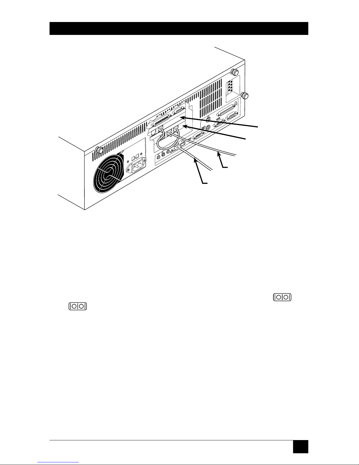
If you want the ServLINK to communicate with the remote site through the public
telephone network, attach its internal modem (the middle daughtercard on the
rear of the ServLINK) to the phone network this way (see Figure 3-6 on the next
page): First run the included RJ-11 phone cable between the modem card’s “LINE”
jack and the “MODEM” jack on the adjacent Access Control card (the bottommost
daughtercard). Then run another standard RJ-11 phone/modem cable (not
included) between the “LINE” jack on the Access Control card and a standard
telephone wall jack.
If you want the ServLINK to communicate with the remote site through your
10BASE-T or 100BASE-T Ethernet LAN, run a straight-through-pinned unshielded
10BASE-T or 100BASE-T cable from the RJ-45 jack labeled on the rear of the
ServLINK to any available network jack. (Be aware that you’ll have to change the
network settings of the ServLINK to comply with those of your network, which
must be done through the operating system; refer to your Windows NT manual.
Also, of course, your network must be configured to support the ServLINK as a
new node—refer to your network’s documentation.)
Video cable to secondary
VGA monitor
Page 22
21
CHAPTER 3: Installation
Figure 3-6. Attaching the ServLINK to the public phone network or a LAN.
3.1.4 A
TTACHING THESERV
LINK D
IRECTLY TO ACONTROLLING
PC’SS
ERIALPORT
If you want the ServLINK to communicate with a local controlling PC as if it were
communicating with the remote site—primarily in order to transfer files—you can
establish a direct serial connection between the ServLINK and the local PC. First
get a standard DB9 female to DB9 female null-modem cable such as our product
code EYN257H. Attach one end of this cable to either of the ServLINK’s two DB9
male serial ports: These are highlighted in dark green and are labeled “ A”
and “ B”. Attach the other end of the cable to one of the PC’s
DB9 male serial ports.
In order for this connection to work, you will need to configure the two
interconnected serial ports to matching data rates, data formats, etc. This can be
done through HyperTerminal™ or some other terminal-emulation program; see
the terminal program’s documentation for instructions.
If you are using Power Management Modules in your system, you can attach the
first Module in your daisychain to one of the Switch’s serial ports. See
Section 3.1.6.
You could theoretically attach other serial devices to the ServLINK’s serial ports,
although this is not necessary or recommended. If you want to do so, please call
Black Box Tech Support to discuss your application first.
Modem card
Access-control card
To a phone jack
To a LAN jack
Page 23

22
SERVLINK™
3.1.5 A
TTACHINGSPEAKERS/HEADPHONES OR AMICROPHONE(OPTIONAL
)
You can attach speakers or headphones and a microphone to the ServLINK if you
want to, although this would only allow the ServLINK to transmit or receive sound
itself—the ServLINK cannot send or receive audio signals to/from the remote site
or to/from the attached PCs.
If you are using speakers or headphones with the ServLINK, plug them into the
jack highlighted yellow and labeled on the back of the ServLINK. If you’re
using a microphone, plug it into the adjacent jack highlighted pink and labeled .
Figure 3-7 shows how this works:
Figure 3-7. Attaching speakers and a microphone to the ServLINK.
3.1.6 A
TTACHINGDEVICES TOOTHERPORTS(OPTIONAL
, NOTR
ECOMMENDED
)
It is theoretically possible to connect other types of devices to other ports on the
rear of the ServLINK, although we don’t recommend doing so because such
connections are unnecessary for the ServLINK’s operation:
• You could plug a USB device into the USB Type A port labeled “ USB”.
• You could attach a parallel printer or a Zip
®
drive to the DB25 female parallel
port highlighted maroon and labeled .
• You could attach an auxiliary stereo audio source to the 3.5-mm stereo audio
jack highlighted light blue and labeled .
Before you make any of these connections, please call Black Box Tech Support to
discuss your application.
To speakers
To microphone
Page 24

23
CHAPTER 3: Installation
3.1.7 A
TTACHINGPOWERMANAGEMENTMODULES(POWER ANDSERIALDATA
, O
PTIONAL
)
How you attach a ServLINK Power Management Module (our product code ACRPWR)
to a main ServLINK unit depends on whether the Module will be controlling
power to the ServLINK itself (see Section 3.1.7.A) or to an attached computer,
router, etc. (see Section 3.1.7.B). Important: Any non-included power cords used
with the Management Modules must be rated for 15 amps minimum. For more
complete information about these Modules, consult their own manual.
3.1.7.A Installing the Module Controlling Power to the ServLINK
Take these steps to install any Module you’ll be using to control power to the
ServLINK itself:
1. If the ServLINK is powered, power it down.
2. Plug one of the RJ-45 cables included with the Management Module into the
“DATA IN” port on the Module, as shown in Figure 3-8.
Figure 3-8. Attaching an RJ-45 cable to the Power Management Module.
3. Plug the other end of this cable into the port marked “DATA” on your
ServLINK’s Access Card, as shown in Figure 3-9.
Figure 3-9. Attaching the same cable to the ServLINK.
RJ-45 control cable to
ServLINK
RJ-45 control cable from
Management Module
Page 25

24
SERVLINK™
4. Find the power patch cord that came with your Management Module. It will
have an IEC 320 female connector on one end and an IEC 320 male
connector on the other. Plug the male end of this cord into the power port
marked “OUT” on the Module. Plug the other end of this cord into the
power inlet on the ServLINK unit.
5. Finally, run the ServLINK’s own power cord from its own inlet to a properly
rated wall outlet. The ServLINK, the Module, and the wall outlet should now
be interconnected, power-wise, as shown in Figure 3-10.
Figure 3-10. Attaching the power cords.
6. Optional: To ensure that you have constant dial-in reboot access to your
ServLINK unit, you can connect a separate modem and phone line to the
Management Module, so that you have a secondary way to reboot the
ServLINK in case the primary phone line is tied up or goes down.
To do this, attach the RJ-45F-to-DB9M adapter included with the
Management Module to the DB9F-to-DB25M adapter that’s also included.
Plug the DB25 male end of this assembly into the DB25 female “DTE” or
“RS-232” port on the modem you’ll be using. Run the other RJ-45 cable
included with the Module from the Module’s “DATA OUT” port to the RJ-45
jack on the adapter assembly, then run a standard RJ-11 phone cable (not
included) from the modem’s “Line” or “Telco” port to the second phone
line’s wall jack.
For details about performing a reboot using this hardware, see
Section 6.6.2.
ServLINK
Module
Page 26

25
CHAPTER 3: Installation
3.1.7.B Installing the Modules Controlling Power to the Attached Devices
Take these steps to install each of the Power Management Modules you’ll be using
to control power to the ServLINK’s attached PC CPUs, routers, and other devices:
1. Power down the device that the Module will be power-controlling.
2. Plug one of the included RJ-45 cables into the “DATA IN” port on the
Management Module.
3a. If this is the first Management Module in the daisychain: Use RJ-45F-to-DB9F
adapter included with the Module to connect the other end of this cable to
one of the ServLINK’s serial ports, as shown in Figure 3-11.
Figure 3-11. Attaching the cable from the first PC’s Module to the
ServLINK.
3b. If this is not the first Management Module in the chain: Connect the other end of
the RJ-45 cable to the “DATA OUT” port on the previous Module in the
chain.
NOTE
Make careful notes of which devices you attach to which Modules, so
that you can associate the two in the ServLINK’s software later, and
have accurate remote control. (The ServLINK’s software will refer to the
first Module in the daisychain as “001,” the second as “002,” and so
forth.) See Section 6.1.2.
Serial control cable
from first Module
RJ-45 to DB9
adapter
Page 27

26
SERVLINK™
4. (Optional) Plug one end of the other RJ-45 cable included with the Module
into the port marked “SERIAL” on the Module you’re installing. Take the
other end of this cable and attach one or more of the Module’s included
adapters (or identical ones if you’ve already used any of them—call Black Box
Tech Support for extras) to connect to a serial device or a device’s serial port
in any of these ways:
• To connect to the serial port of the Module’s attached PC, router, network switch, etc.
(the standard application) or to the serial port of another such device: Attach the
included RJ-45F-to-DB9F adapter to the cable and plug the adapter into the
device’s DB9M serial port. (If the device has a DB25M serial port instead,
you’ll also need a non-included DB9M-to-DB25F adapter.)
• To connect to a modem, multiplexor, or other RS-232 DCE with a DB25F connector:
Attach the included RJ-45F-to-DB9M adapter to the cable, then add the
included DB9F-to-DB25M adapter. Plug the DB25M end of the adapter
assembly into the device.
• To connect to any other RS-232 device that can be connected to a PC’s serial port:
Attach the included RJ-45F-to-DB9M adapter to the cable, then (if
necessary) add the included DB9F-to-DB25M adapter. Get any cable,
adapters, etc., that you’d run from a PC’s DB9M or DB25M serial port to
the device. Plug these into the DB9M or DB25M end of the Module’s
adapter assembly and run them to the device. (Keep in mind that the
normal distance limit for RS-232 communication is 50 ft. [15.2 m].)
5. (Optional) If this is the last Management Module in the daisychain: Plug one end
of an RJ-45 cable (the other included one if you didn’t already use it in step 4,
one just like it otherwise) into the “DATA OUT” port of this Module. Take
the other end of this cable and attach one or more of the Module’s included
adapters (or identical ones if you’ve already used any of them—call Black Box
Tech Support for extras) to connect to a “pass-through” serial device that you
can communicate with when none of the Power Management Modules are
active. Refer to the “bullet points” in step 4 above for how to do this.
6. Connect the male (inlet) end of the Module’s included power patch cord to
the port marked “POWER OUT” on the back of the Management Module.
7. Connect the female (outlet) end of this cord to the power inlet on the device
that the Module will be controlling.
8. Finally, run the device’s power cord from its own inlet to a properly rated wall
outlet.
Page 28

27
CHAPTER 3: Installation
3.1.7.C After Installing the Modules
Once you’ve installed all your Modules, cables, power cords, etc., your powermanaged ServLINK system should be ready to be powered up. When you do so
(see the next section), the ServLINK’s control software will automatically sense that
you’ve added the Power Management Modules. Refer to Section 5.1.3 for
instructions on configuring the Modules.
Figure 3-12 shows the logical layout of a ServLINK system that includes Power
Management Modules, and Figure 3-13 (on the following page) shows the physical
layout of such a system.
Figure 3-12. Management-Module connection logic.
IN OUT
IN OUT
SERIAL
DATA
ACCESS CONTROL CARD
DATA
RS232 COMM
IN OUT
IN OUT
SERIAL
DATA
RS232 COMM
OTHER SYSTEMS
MODEM
POWER MANAGEMENT MODULE
SERVLINK UNIT
SERVER PC
POWER MANAGEMENT MODULE
SERVLINK’S DEDICATED
FIRST DEVICE’S
OPTIONAL
OTHER DEVICES’ POWER MANAGEMENT MODULES,
PASS-THROUGH DEVICE AT END OF CHAIN IF DESIRED
Page 29

28
SERVLINK™
Figure 3-13. A ServLINK system with Management Modules installed.
To
optional
modem
To additional Power
Management Modules
attached to other devices,
and/or to an optional pass-
through serial device
Page 30

29
CHAPTER 3: Installation
3.1.8 A
TTACHINGPOWERDIRECTLY(NOPOWERMANAGEMENTMODULES
)
If your system doesn’t include Power Management Modules, take these steps to
hook it up to AC power: First make sure that the ServLINK’s power switch is OFF,
then run the included power cord (shown in Figure 3-14) between the IEC 320
power connector on the ServLINK and an appropriate AC wall outlet. (This outlet
must be near the equipment and must be easily accessible so that the ServLINK
can be easily unplugged if it ever needs servicing.) Plug in the rest of the attached
devices.
Figure 3-14. Attaching the power cord to the ServLINK.
Power cord
Page 31

30
SERVLINK™
3.2 At the Local Site: Initial Power-Up
When all of your equipment is in place, take these steps to power up the devices at
your local site (you can power up the remote PC and monitor at any time):
1. If you’ve installed Power Management Modules: Turn the Modules ON.
2. Turn ON the ServLINK by pressing the large button marked on the
ServLINK’s front panel. The ServLINK will begin booting (it runs Microsoft
Windows NT).
3. Turn ON the attached monitor and any other powered attached devices and
peripherals.
4. If you’re connected to a network, follow your normal operating procedures to
log into your network as usual. You should be able to start working with the
ServLINK right away: It ships with the default Windows NT user name
“Administrator” and no password, so until you change these settings, you can
simply press [Enter] to log in.
Once you’ve logged in, pcANYWHERE loads, followed by the ServLINK
application. Once the system has completely booted, you should see the line
“ServLINK Remote Control System - Main Menu” at the top of your screen.
(Please note that ServLINK ships with only the TCP/IP network protocol
installed and is configured with a static IP address. Consult with your network
administrator about how to configure the network to support the ServLINK.)
5. Turn ON any attached KVM switches.
6. Turn ON your CPUs.
Your system should now be ready for initial configuration.
NOTE
Before having the ServLINK serviced—if you ever need to—power it
down by turning it OFF and unplugging it, or by shutting OFF power to it
through its Power Management Module. (Also power down all of the
attached computers if possible.)
Page 32

31
CHAPTER 3: Installation
3.3 At the Remote Site
To access the ServLINK and your host PCs remotely, your remote location must be
equipped with a PC running pcANYWHERE software and with either a modem (if
you’ll be dialing into the ServLINK) or a network card and an IP address on the
same network as the ServLINK (if you’ll be controlling it across a LAN). Once you
have these things in place, you can establish a connection to your ServLINK and
begin remote operation. If you’re doing this over the phone, make sure that you
know the phone number that you’ll need to dial to reach your ServLINK.
For additional information about remote access, see your pcANYWHERE
documentation.
Page 33

32
SERVLINK™
4. Configuration
4.1 Configuring the ServLINK to Switch Between Your PCs (KVM-Switched
Systems Only)
The ServLINK is designed to handle switching between the PCs in your system
through an on-screen menu (see Section 6.1.1). When you select a PC from the
menu, the ServLINK sends the appropriate keystroke commands to an attached
ServSwitch family KVM switch. However, different ServSwitch models recognize
different switching commands. For this reason, if you’ve connected your ServLINK
to a ServSwitch system, you might need to configure the ServLINK so that it can
perform switching properly.
If you’ve only connected a single PC to your ServLINK, the ServLINK won’t need
to do any switching, but you need to tell the ServLINK that. In Section 4.1.2, take
step 1, then skip ahead and take steps 9 through 16—refer to those steps for details
about what you need to enter.
4.1.1 THES
TANDARDCONFIGURATION
The ServLINK comes preconfigured with a switching menu (and a corresponding
set of keystroke commands) that will work for a basic system. If your system meets
all of the following requirements, you won’t need to configure the ServLINK’s
switching menu, so you can skip ahead to Section 4.2:
1. You have 14 or fewer PCs connected to the ServLINK.
2. All of the PCs are connected to the ServLINK through any version (original,
-R2, -R3, etc.) of one of these ServSwitch models: ServSelect™ (our product
codes KV104A or KV108A), ServSwitch Multi (KV150A or KV160A),
ServSwitch™ Multi MX (KV155A), or ServSwitch™ Multi Z8 (KV158A). Any
ServSwitch Multi must be assigned a chassis address from 0 to 10.
3. The system has only one user.
If your configuration varies from this one, follow the steps in Section 4.1.2 to add
computers to your ServLINK system’s switching menu.
Page 34

33
CHAPTER 4: Configuration
4.1.2 E
NTERING THECHANNELADDRESSES OFYOURPCS
The first thing you’ll need to do to enable the ServLINK to switch between your
PCs is to tell it what each PC’s assigned KVM-switch channel address is. (If you’re
only attaching a single PC to the ServLINK, you need to tell the ServLINK that the
PC doesn’t have a channel address instead.) The “channel address” or “port address”
of a PC CPU in a KVM-switched system is the name or number—usually associated
with a particular switch channel or CPU port—that you give to the KVM switch in a
keystroke command in order to get the KVM switch to switch to that PC. Take
these steps to enter a PC’s address into the ServLINK’s memory:
1. Turn ON the ServLINK if you haven’t done so already. It should automatically
run pcANYWHERE and the ServLINK application, so that the main menu of
the ServLINK is displayed (see Figure 6-2 at the start of Chapter 6 for a
picture of the menu).
If you only have a single PC attached to the ServLINK, skip ahead to
step 9.
2. Pull down the Keyboard menu and select “Create Keyboard Macros.”
3. Click the “Add” button.
4. In the “Macro Description” field, type in the address of the channel (port) on
the KVM switch that the PC is attached to. Note that this entry is just a
description—you’ll be creating the actual keyboard-command macro that the
ServLINK will use in the next few steps—so you can include words such as
“Enter” that describe other keystrokes in the switching command or what
have you. Here are a few sample addresses for various ServSwitch models (see
your switch manuals for more details about how addressing works):
• Regular ServSwitch, ServSwitch™ Ultra, ServSwitch™ Affinity, Matrix
ServSwitch™, and compatible models: No matter how many switches and PC
CPUs are in your system, the master switch(es) simply number all of the ports
and CPUs sequentially, just as if they were all attached to the same switch. So
the address of CPU 35 would be just “35”.
• ServSwitch™ Multi, ServSelect, and compatible models: Addresses consist
of the switch’s “chassis address” plus a port letter. So the address of the PC
CPU on port “J” of chassis “14”, for example, would be “14J”.
• ServSwitch™ Duo, ServSwitch™ Wizard, ServSwitch Wizard Pro, and
compatible models: If there’s only one switch in your system, the addresses of
the attached PC CPUs are a simple two-digit port number, such as “05” or
“12” (leading zeros are required for CPUs 1 through 9). If there are several
cascaded switches in your system, the address consists of the complete “port
path”: The address of the CPU on port 3 of a switch attached to port 2 of the
master switch would be “0203”.
Page 35

34
SERVLINK™
• ServSwitch™ Elite models: The attached PC CPUs can be addressed with
names if you’ve assigned names to them in the Elite menus (“webserver3”, for
instance); they can always be addressed with numbers.
If there’s only one
switch in your system, the numeric addresses are a simple two-digit port
number, such as “05” or
“12” (leading zeros are required for CPUs 1 through
9). If there are several cascaded switches in your system, the address consists of
the complete “port path,” with port numbers separated by dashes: The address
of the CPU on port 3 of a switch attached to port 2 of the master switch would
be “02-03”.
In the next few steps, you’ll enter the actual series of keystrokes that the ServLINK
will have to use to switch to the PC.
Normally, when you would send a switching command to a KVM switch from
your keyboard, you would press and release or press and hold one or more special
“hotkeys” that alert the switch to expect a command, then press and release the
keys that make up the address of the desired PC in sequence. (Most switches then
require you to finish the command by either releasing the hotkeys or pressing and
releasing [Enter].)
For example, if a PC CPU attached to a ServSwitch Multi had the address “25A”,
to switch to that CPU you would press and release the ServSwitch Multi’s hotkeys
(normally [Num Lock] and keypad minus [–]), then press and release [2], then
press and release [5], then press and release [A], then press and release [Enter].
Because the switch’s hotkeys will be used for other keyboard commands, those
are set separately on the ServLINK (see Section 6.4) and you don’t have to enter
them here. You do have to select all of the other characters in the command,
however:
5. In the left-hand column labeled “Double Click for Key Press,” double-click the
first letter, number, or other character of the PC’s channel address. For our
example CPU with the address “25A”, that first character would be a “2”.)
6. Double-click the same number or letter in the “Double Click for Key Release”
column. This tells the ServLINK to release the key once it has been pressed.
This keystroke should appear in the “Macro Created” box located on the far
right. (Key names enclosed in brackets represent keypresses; key names
enclosed in greater than and less than signs represent key releases.)
7. Repeat steps 5 and 6 for the remaining characters that make up your
complete channel address, including any end-of-command characters.
(Unless your KVM switch explicitly requires uppercase letters, use lowercase
letters only for channel addresses.) For our example CPU with the address
“25A”, the Macro Created box should read “Press [2], Release <2>, Press [5],
Release <5> , Press [a], Release <a>, Press [Enter], Release <Enter>” when
you’re finished.
Page 36

35
CHAPTER 4: Configuration
8. Click the “OK” button to save the address macro to the ServLINK’s memory.
Repeat steps 3 through 8 for each PC whose address you want to add to the
ServLINK’s memory. Click the “Exit” button in the “Create Keyboard Macro” box
to go back to the Main Menu when you’re done. Now take one last set of steps:
9. Pull down the Switch menu and choose the “Switch PCs” option. This will
bring up the “Switch PCs” dialog box ( a list of PCs connected to the
ServLINK).
10. To add a new computer, click the “Add” button.
11. The “PC Settings” dialog box will appear. In the “PC Description” field, enter
a description for this computer. In KVM-switched systems, it’s generally best
to use the same description for each PC as the one (if any) assigned to that
PC in the menu system of the KVM switch.
12. In the “Switch Box Command” field, make sure that you have selected the
hotkey combination that initiates command mode for your switch. The
default is set for [Num Lock] and keypad minus [–].
If you have a single PC attached to the ServLINK, select “Switch Box Not
Applicable.”
13. In the “Switch Box Select PC” field, select your channel address out of the
drop-down menu. Channels that you configured in the previous section
should appear in this menu.
If you have a single PC attached to the ServLINK, select “Switch Box Not
Applicable.”
14. The remaining settings in this menu are automatically generated and should
not under normal circumstances be changed. Select “OK” to take you back to
the main Switch PCs box (“List of PCs”).
15. If you have multiple KVM-switched computers attached to the ServLINK, repeat
steps 10 through 14 for every computer you want to add to the list.
16. When you’re finished, click “Exit” to return to the Main Menu.
Page 37

36
SERVLINK™
4.2 Configuring PCs
Follow the steps below to set up each PC attached to the ServLINK system. These
instructions assume that you’re connected to the PCs through a KVM switch.
1. At the Main Menu, pull down the Switch Menu to the “Switch PCs” option.
This will give you a list of PCs connected to the ServLINK. There will be
14 PCs set up as the default menu selections, labeled “Black Box Switch Box Channel A” through “Black Box Switch Box - Channel N” (suitable for PCs
connected to a ServSwitch Multi or ServSelect). Any channels that you added
in the previous section will also appear.
2. Highlight the first PC you want to set up. If you are configuring a PC using
the default settings for Channels A through M, click the “Settings” button.
Here, in the PC Description field, you can rename the channel to whatever
description you will recognize your computer by. Generally, it is best to use
the same description that you use for your switch.
Also, while in this menu, check the “Switch Box Command” setting and
make sure that it reflects the keyboard sequence your switch uses to enter
command mode. Click “OK” when you’re finished.
3. Choose the “Select Host PC” option from the Switch menu and click “OK.”
The ServLINK will go into “Host Mode” and switch to that computer
immediately. Read the notice that appears on your screen and click “OK” to
clear it.
4. Tap the right Shift key three times to bring up the Host Mode Properties
dialog box.
5a. If the screen looks acceptable (level of brightness, contrast, etc.), go to the next PC by
clicking the “Menu Mode” button in the Host Mode Properties dialog box,
then repeat steps 1 through 4.
5b. To make changes in the appearance of your video, select the “Video Advanced” tab
in the Host Mode Properties dialog box. Click the “AutoDetect All” button.
When the “Apply” button becomes active, click it. If the screen looks
acceptable now, go to the next PC by clicking the “Menu Mode” button in the
Host Mode Properties dialog box, then repeat steps 1 through 5. Otherwise,
continue with steps 6 through 10.
6. Select the “Video Settings” option from the Host Mode Properties dialog box.
7. Use the slider bars in this window to adjust the brightness and contrast
settings until you are satisfied with them, then click the “Apply” button.
Page 38

37
CHAPTER 4: Configuration
8. Click the window’s left-, right-, up-, and down-buttons to adjust the position of
the ServLINK window. When you’re satisfied that it’s in the right spot, click
the “Apply” button.
9. Exit Host Mode by clicking the “Menu Mode” button.
10. Repeat steps 1 through 10 for each additional PC in your system.
4.3 Host PC Settings
In this manual, we refer to the PC you’re controlling remotely through the
ServLINK as the “Host PC.” If your ServLINK is connected to a KVM switch, you
will have multiple Host PCs, because every PC attached to the switch is a host. The
ServLINK is designed to allow complete on-site and remote control of a Host PC
without requiring you to change the configuration of, or install any software on,
the Host PC. However, changing several minor settings on the Host PC will greatly
enhance ServLINK’s performance. Follow the steps below to maximize the
ServLINK’s capabilities.
1. Set your color scheme on the Host PC to contain only black, bright white,
red, and green.
2. Set the Host PC’s video resolution to the lowest possible setting that’s
acceptable for your applications, and set its refresh rate to the lowest possible
acceptable setting between 56 and 70 Hz. (The 640 x 480 resolution setting
will yield the fastest frame rate.) Do not select any interlaced resolution/
refresh rate.
3. Set your Host PC’s mouse pointer speed to “slow” through your Windows
®
application. (Once the ServLINK’s mouse speed is set to “fast,” this should
ensure that the mouse handling on the two machines is properly aligned. See
Section 4.4 for more information.)
4. Disable any screen savers or settings that put the Host PC in a sleep mode.
Access through the ServLINK will be faster without them.
5. Replace animated icons that cause constant screen changes on the Host PC.
This reduces the amount of screen data transmitted through the ServLINK,
speeding up redraw and enhancing performance.
Page 39

38
SERVLINK™
4.4 ServLINK and Remote-Site Settings
To configure your ServLINK and remote-site settings for optimal operation, follow
the steps below. Begin by placing your ServLINK in Host Mode. From the Main
Menu bar, pull down the “Host Mode” menu and select “Switch to Host Mode.”
The desktop of the currently selected PC will appear, along with a crosshair mouse
cursor. Tap the right Shift key on your keyboard three times to bring up the Host
Mode Properties dialog box.
1. In the Host Mode Properties box, choose the “Keyboard/Mouse” option. Set
your ServLINK mouse speed to “fast.” This setting, along with the Host PC’s
mouse speed being set to “slow,” creates fairly close mouse alignment—that is,
the position of the crosshair cursor on your remote screen (the spot that the
ServLINK thinks the mouse is pointing to) will usually match the position of
the selected PC’s mouse pointer (the spot that the PC thinks the mouse is
pointing to).
If you are at the local user station attached to the ServLINK and your mouse
alignment is not the greatest—if, for example, you try to click one window
button and the PC’s mouse pointer lands and clicks on the neighboring
button—tap the left Shift key four times. This will align the mouse by moving
both the crosshair cursor and the PC’s mouse pointer to the upper left-hand
corner of your screen.
If you are at a remote user station and your mouse alignment is poor, move
the cursor to the upper left corner and the mouse will align there within a
second or two.
2. If you are at the local user station attached to the ServLINK, check in the Host
Mode Properties dialog box to make sure that you are using the ServLINK’s
default setting of 256 colors.
If you are at a remote user station, configure pcANYWHERE for 16-color
operation as described in the pcANYWHERE manual.
Page 40

39
CHAPTER 5: Basic Switching and Host-Mode Options
5. Basic Switching and
Host-Mode Options
5.1 Switching to a Remote PC: Host Mode
Once your ServLINK system has been connected and configured, you will be able
to connect to it through any computer that has the pcANYWHERE software
installed. Information on connecting to a remote PC can be found in your
pcANYWHERE software.
The first time you connect to the ServLINK, the ServLINK’s Main Menu will
appear, as shown in Figure 5-1.
Figure 5-1. The Main Menu.
Page 41

40
SERVLINK™
To switch to a computer connected to your ServLINK, pull down the Switch menu
from the bar at the top of the screen and select the “Switch PCs” option. A list of
available computers will appear, as shown in Figure 5-2.
Figure 5-2. The Switch PCs dialog box.
Select the computer you want to switch to in either of two ways: Either double-click
it, or use the arrow keys to highlight it and click Enter. (While a computer is
selected, the status display at the bottom of the Main Menu will verify that it’s the
active Host PC.) This command causes the ServLINK to go into “Host Mode” and
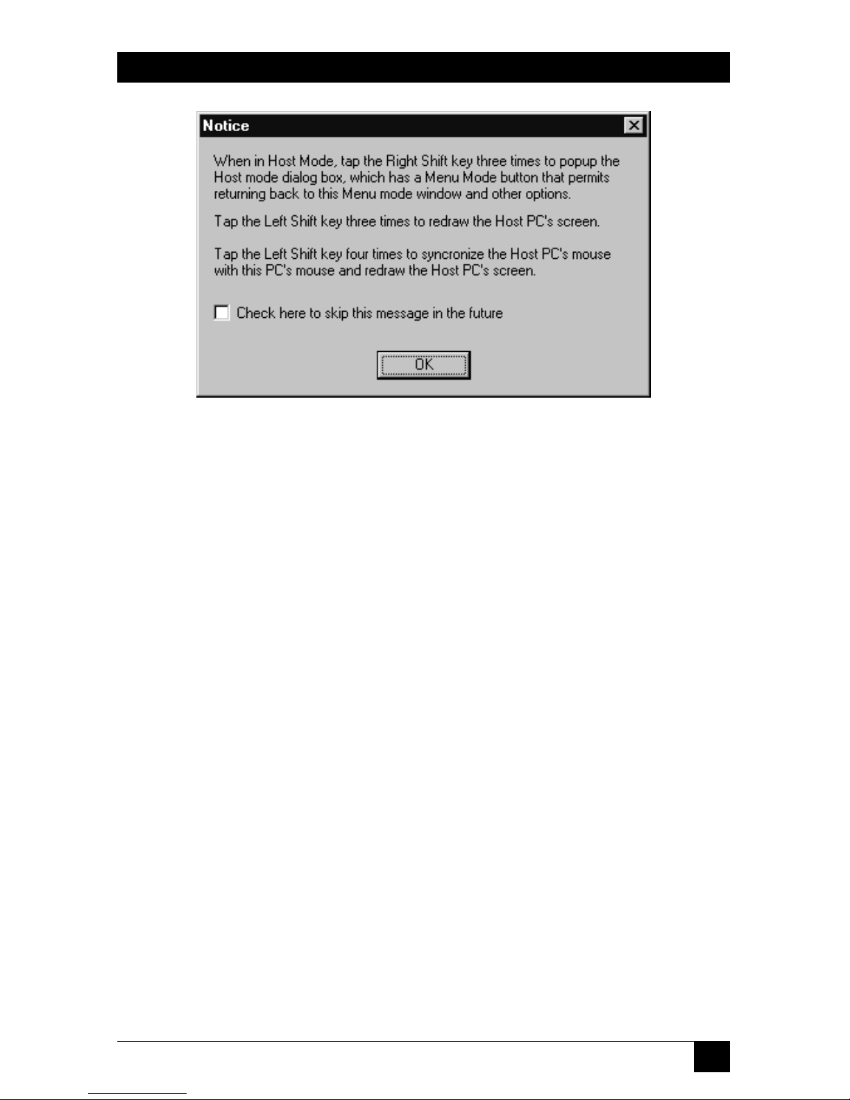
switch to the chosen PC. The first time you do this, you’ll see the notice shown in
Figure 5-3 on the next page.
Page 42
41
CHAPTER 5: Basic Switching and Host-Mode Options
Figure 5-3. The Host Mode notice.
When you click “OK”, the selected PC’s desktop will appear on your monitor and
you can use it just as if your keyboard, monitor, and mouse were connected directly
to it. The Host Mode display will differ from a regular desktop in one way: In
addition to the regular mouse pointer, which reflects where the selected PC thinks
the mouse is, a crosshair pointer will show you where the ServLINK thinks the
mouse is.
CAUTION!
We suggest that you use different wallpaper for the ServLINK’s desktop
than you do for any attached Windows NT PCs. Otherwise it can be very
easy to mistakenly change the settings of the ServLINK itself when you
think you’re in Host Mode changing the settings of an attached PC.
While you’re in Host Mode, the function keys at the top of your keyboard can be
very useful. Click [F1] to get on-line help. Click [F2] through [F11] to send macros
for certain Windows related key sequences to the Host PC (see Section 5.2.3 for
details). Click [F12] to bring up a list of all available keyboard macros, any of which
you can send to the attached Host PC or KVM switch (see Section 6.4.1).
Most other settings you can change and options you can select in Host Mode,
including switching between Host PCs and exiting back to Menu Mode, are
available through the Host Mode Properties dialog box, which you can bring up on
your screen by clicking your keyboard’s right [Shift] key three times. See
Section 5.2.
Page 43

42
SERVLINK™
5.2 Host Mode Properties
While you’re working with a Host PC in Host Mode, you can click the right [Shift]
key three times to bring up the Host Mode Properties dialog box. This box has
four main buttons: Click “OK” to save any Host Mode settings you change,
“Cancel” to abort any changes you made, “Apply” to observe the effect of the
changes without saving them, or “Menu Mode” to simply quit Host Mode and
return to the ServLINK’s Main Menu.
This dialog box is used to control six groups of Host Mode settings, organized
under six tabs. These tabs and their settings are described in the six subsections
that follow.
5.2.1 T
EST
PCI C
ARD
When you select the “Test PCI Card” tab, you’ll see the dialog box shown in
Figure 5-4. If you ever have to contact Black Box regarding problems with your
ServLINK, our technicians might ask you for the list of PCI Card characteristics
shown here, which can be useful for troubleshooting purposes.
If you are having severe video problems, click the “Enable Video Capture”
checkbox OFF. When video capture is disabled, the ServLINK doesn’t try to display
video from the Host PC, so that you can work with the ServLINK’s screens and
menus without the PC’s video making them unwatchable or unusable.
Figure 5-4. Host Mode Properties: Test PCI Card.
Page 44

43
CHAPTER 5: Basic Switching and Host-Mode Options
5.2.2 K
EYBOARD/MOUSE
When you select the “Keyboard/Mouse” tab, you’ll see the dialog box shown in
Figure 5-5.
Figure 5-5. Host Mode Properties: Keyboard/Mouse.
• Click the “Enable Keyboard” checkbox to enable or disable your keyboard.
• Click the “Enable Mouse“ checkbox to enable or disable your mouse.
• The “Turbo Mode” feature is not enabled on current versions of the
ServLINK. Leave this checkbox empty (OFF).
• Click “Slow,” “Medium,” or “Fast” to set the “Pointer Speed” (the speed of the
ServLINK’s crosshair mouse cursor). For best mouse control, set this to “Fast”
and set the speed of the Host PC’s mouse to “slow.”
• Click the “Reset Keyboard Interface” button to send a keyboard-reset
command to the attached Host PC or KVM switch. This is equivalent to “hotplugging” the keyboard. This command will not reset the mouse; however, the
ServLINK does have predefined keyboard macros that will send a mouse reset
to the ServSwitch Multi (“Reset Mouse - ServSwitch”) or ServSelect (“Reset
Mouse - ServSelect”); see Section 5.2.3.
Page 45
44
SERVLINK™
5.2.3 S
HORTCUTKEYS
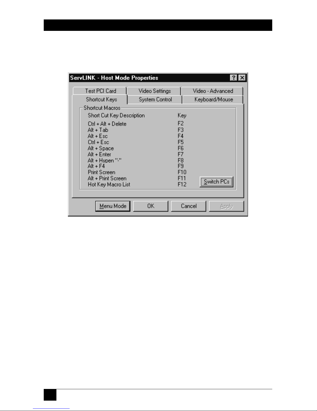
When you select the “Shortcut Keys” tab, you’ll see the dialog box shown in
Figure 5-6.
Figure 5-6. Host Mode Properties: Shortcut Keys.
Under Shortcut Keys you will find a listing of special function-key shortcuts for
common sequences of Windows related keystrokes. If you press these keystrokes
directly on your keyboard, they’ll be intercepted by the ServLINK itself and won’t
reach the PC. So in Host Mode (and only in Host Mode), you can press a shortcut
function key to have the ServLINK send the function key’s assigned keystrokes to
the Host PC.
• Press function key [F12] at any time while you’re in Host Mode to bring up a
list of all of the keyboard macros that are programmed into your ServLINK.
This is equivalent to the main Keyboard Macro dialog box discussed in
Section 6.4.1, except that the “Send to PC” button is active, which you can click
to send any defined macro (whether or not a shortcut key is assigned to it) to
the Host PC or intermediate KVM switch.
• Click “Switch PCs” in this box to bring up a list of available PCs/channels. This
is equivalent to the main Switch PCs dialog box discussed in Section 6.1.1.
Page 46
45
CHAPTER 5: Basic Switching and Host-Mode Options
5.2.4 V
IDEOSETTINGS
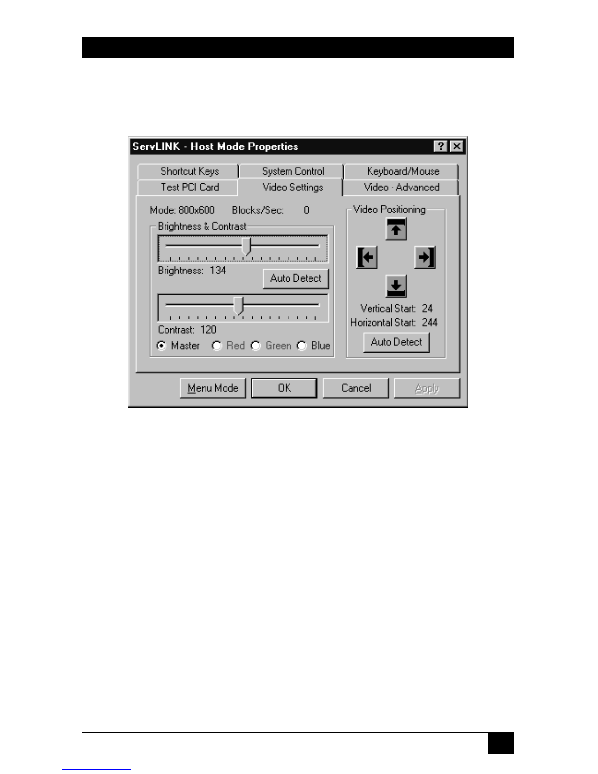
When you select the “Video Settings” tab, you’ll see the dialog box shown in
Figure 5-7.
Figure 5-7. Host Mode Properties: Video Settings.
• Click the “Master” button to adjust the brightness and contrast of the total
video image from the Host PC, from 0 to 255. Or click “Red,” “Green,” or
“Blue” to adjust just those portions of it, from 0 to 127. Then drag the
Brightness and Contrast bars and click “Apply” to check how the video looks;
click “OK” when you’re satisfied. (In most cases, clicking “Auto Detect” will
cause the ServLINK to arrive at the correct settings for your system.)
• Click the “Video Positioning” arrows to move the Host PC’s video display on
your monitor if it’s positioned poorly. After every few presses of the arrow keys,
click “Apply” to check how the video looks; click “OK” when you’re satisfied.
(Again, clicking “Auto Detect” will usually cause the ServLINK to move the
display to the right spot for your system.)
• Be aware that clicking the “Auto Detect All Settings” button under the “Video Advanced” tab (see Section 5.2.5) will autodetect and automatically adjust not
only the Advanced settings, but the Brightness, Contrast, and Video
Positioning here as well.
Page 47
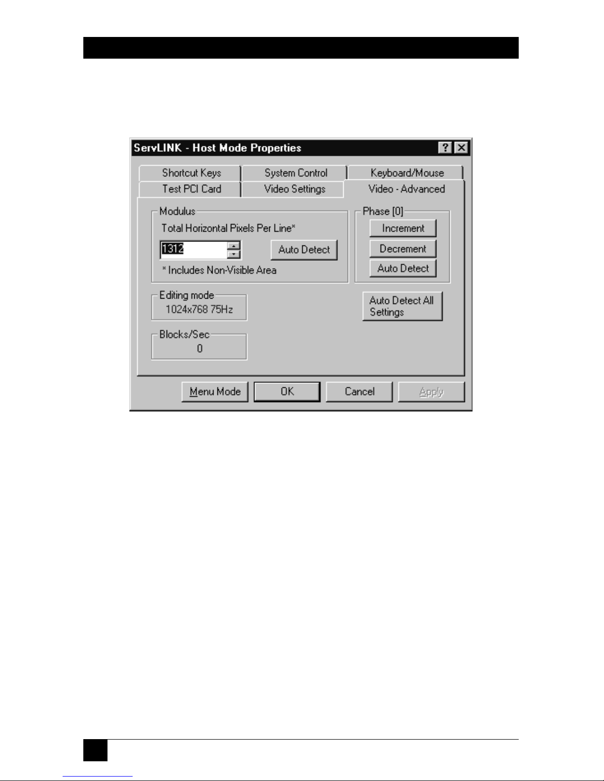
46
SERVLINK™
5.2.5 V
IDEO
- A
DVANCED
When you select the “Video - Advanced” tab, you’ll see the dialog box shown in
Figure 5-8.
Figure 5-8. Host Mode Properties: Video - Advanced.
Under normal circumstances, the ServLINK should be able to autodetect all of
these settings; click “Auto Detect All Settings” to see if any video problems go away.
(When you do so, the ServLINK will also autodetect Brightness, Contrast, and
Video Positioning under the “Video Settings” tab; see Section 5.2.4.) However, if
you’re still getting snow or flickering in the Host PC’s video display, you might
want to try to customize some of these video settings, because if snow or flickering
is not eliminated, a remote user’s screen performance may be reduced by as much
as one-tenth of normal. Take these steps:
If the Host PC’s screen has vertical bands of flickering or jumps from left to right, the
Modulus setting needs to be changed first. Depending on the colors being
displayed on the Host PC’s screen, this problem may not be immediately obvious.
This problem is clearly visible on screens containing a lot of gray, particularly the
Windows 50% gray screen that appears whenever the Windows Shut Down option
is selected from the Windows Start-button menu. To correct this problem and
generally any problem affecting vertical stability, increase or decrease the Modulus
setting by 8 until the problem disappears. Generally it should not be necessary to
increase or decrease the modulus setting by more than 16. The Modulus setting
should always be a multiple of eight; so, for example, 792, 800, and 808 are proper
Page 48

47
CHAPTER 5: Basic Switching and Host-Mode Options
modulus settings, but 801 through 807 are not. Click the Auto Detect button in the
Modulus area to autodetect the Modulus only
If the Host PC’s screen shows a large amount of snow or appears grainy, then the Phase
adjustment needs to be changed. Click the Increment or Decrement buttons to
determine the setting that results in the best screen. No more than 16 clicks on
theses button should be necessary to determine the best position. After the
Modulus and Phase have been adjusted, you might need to readjust the Master
Brightness and Contrast slider bars under the Video Settings tab (see
Section 5.2.4) to correct any color flickering appearing on portions of the screen,
such as in multi-colored icons. (In some cases it may not be possible to eliminate
flickering entirely, especially in small icons that use slight variations of color.) Click
the Auto Detect button in the Phase area to autodetect the Phase only
Editing Mode and Blocks/Sec aren’t user-settable; they’re fields that provide
information about the Host PC’s video:
• Editing Mode is the resolution and refresh rate of this video.
• Blocks/Sec is the number of 64-pixel chunks of the video image that the
ServLINK is forwarding to your user station each second.
Page 49
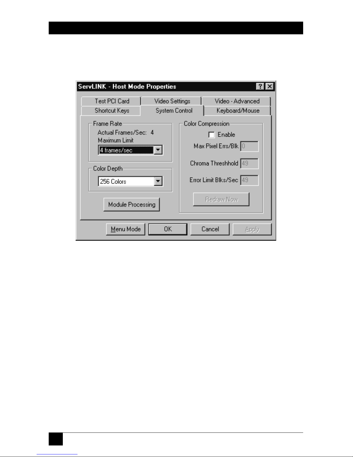
48
SERVLINK™
5.2.6 S
YSTEMCONTROL
When you select the “System Control” tab, you’ll see the dialog box shown in
Figure 5-9.
Figure 5-9. Host Mode Properties: System Control.
5.2.6.A Frame Rate, Color Depth, and Module Processing
• Adjust the Frame Rate’s Maximum Limit upward if the ServLINK is not
updating its display of the Host PC’s video quickly enough (video changes and
mouse movement are very jerky). Adjust the limit downward if the ServLINK is
trying to update this display too quickly for your modem to handle (you get
“bandwidth exceeded” messages, mouse movement freezes, or—in extreme
cases—pcANYWHERE crashes). The default setting is 4 frames per second;
other available settings include 1, 2, 8, or 16 frames per second, or 2, 4, 8, or
16 seconds per frame. If you need a higher frame rate than your modem is
capable of, consider reducing the color depth (see the next paragraph).
•
If you’re at the local user station, you’ll want to adjust the color depth to 256 colors
to take advantage of the good color fidelity that the ServLINK can achieve
locally. But if you’re at a remote user station, you’ll want to set this to 16 colors,
and set pcANYWHERE to use 16 colors as well (consult its manual for
instructions).The default setting is 256 colors; other available settings include
black & white, 4-level grayscale, and 16 colors. As mentioned above, reducing
the color depth—particularly from 256 to 16 colors—can greatly increase your
frame rate, and there is often no discernible difference in video quality.
Page 50

49
CHAPTER 5: Basic Switching and Host-Mode Options
• If you need to interact with any Power Management Modules attached to the
system while you’re in Host Mode, click the Module Processing button to bring
up the Control Module Processing dialog box (see Section 6.1.2).
5.2.6.B Color Compression
Color compression should always be enabled when you’re connected to the
ServLINK remotely, because this will dramatically increase remote access speeds by
reducing the amount of screen data that needs to be transmitted by a remote PC.
The Enable box is checked automatically when a remote user connects and it is
cleared automatically when they disconnect.
• Max Pixel Errs/Blk
This adjusts the amount of screen changes that are transmitted over the
remote connection. When this parameter is set to zero, ServLINK repaints any
block of 64 pixels that has even a single pixel change. A setting of 3 indicates
that if 3 or more pixels in the block change, ServLINK should post the block to
the screen; otherwise the block will not be transmitted or redrawn.
The MaxPixel setting should be set to the lowest nonzero value that still
results in an acceptable refresh rate for the remote user.
• Chroma Threshold
Increasing the value of this setting reduces ServLINK’s sensitivity to variations
in color. Minor noise or variations in the Host PC’s video-output signal can
cause slight variations in color causing pixels to “twinkle” between color
settings. This effect is treated as a change on the screen which may cause
unnecessary screen blocks to be transmitted.
The normal range of settings for the Chroma threshold are 8 to 30 for 256
colors and 20 to 60 for 16 colors.
• Error Limit Blks/Sec
When you’re connected remotely, a Host PC’s video output may be so far out
of adjustment that the display on your screen is completely unstable. When
this occurs, pcANYWHERE (or whatever remote-access software you’re using)
will virtually lock you out while attempting to transmit massive amounts of
screen updates to you. To prevent this from occurring, a threshold may be set
that represents the maximum number of screen-block updates that may occur
per second. If this maximum is exceeded for five continuous seconds,
ServLINK automatically freezes the Host PC’s screen to prevent any further
updates from being transmitted, so that corrective action can be taken.
Page 51
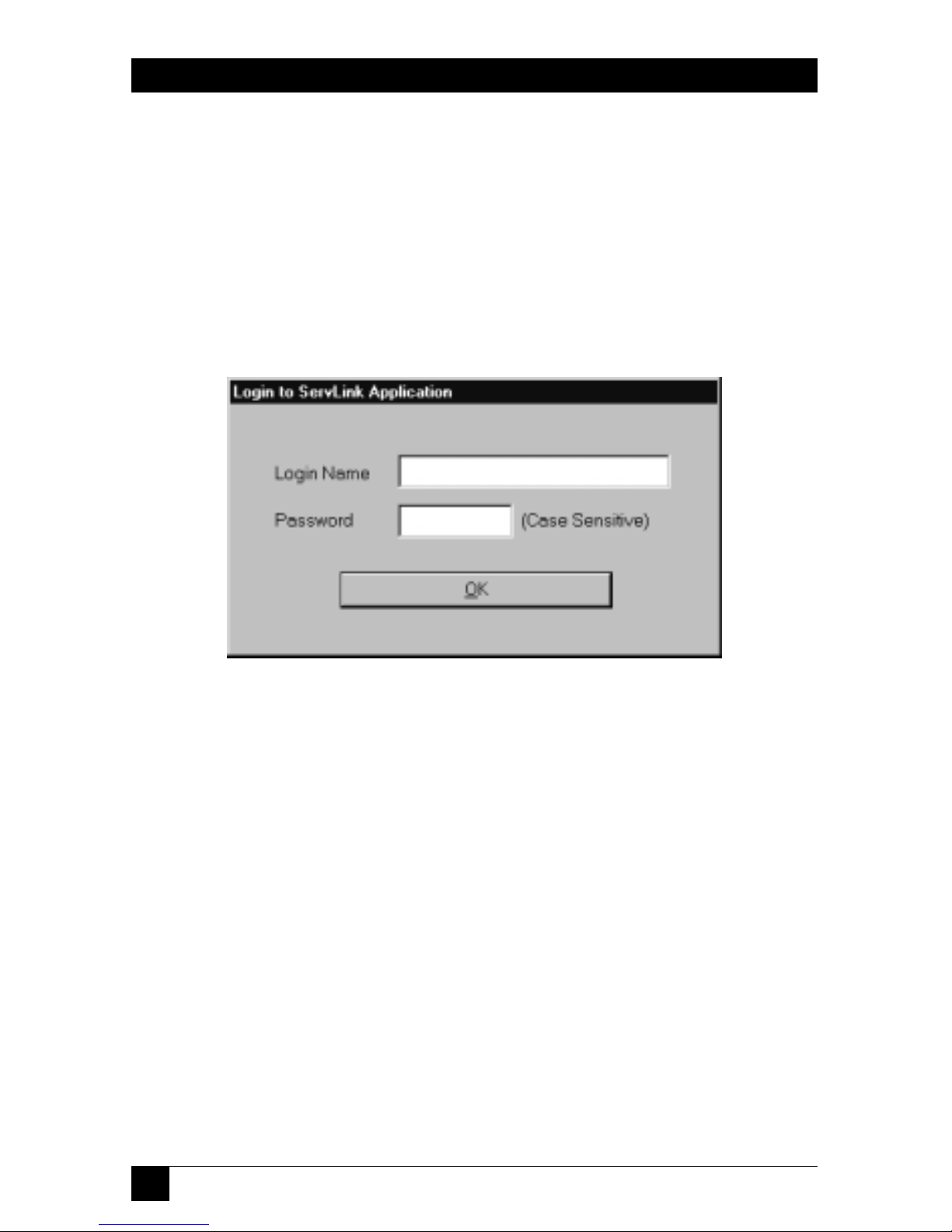
50
SERVLINK™
6. The Menu System
When you power up the ServLINK, its Windows NT Workstation operating system
will initialize. You will be asked to choose between straight NT and NT [VGA];
choose straight NT. Then the main ServLINK application will run automatically.
A “splash screen” will appear, and then if password security is enabled an NT
window will pop up in the middle of it prompting you to “Press Ctrl + Alt + Del to
log on.” When you press the [Ctrl], [Alt], and [Del] keys, the login box shown in
Figure 6-1 will appear, prompting you for your user ID and password.
Figure 6-1. The Login box.
Page 52

51
CHAPTER 6: The Menu System
If passwords are disabled, or once you enter a valid user ID and password, the
ServLINK’s Main Menu will appear, as shown in Figure 6-2.
Figure 6-2. The Main Menu.
As you can see, you have seven primary menus to choose from; these are described
in Sections 6.1 through 6.7.
Page 53

52
SERVLINK™
6.1 The Switch Menu
The first primary option available under the Main Menu is “Switch.” When you pull
down the Switch Menu, you’ll see three selections, as shown in Figure 6-3.
Figure 6-3. The Switch menu.
• Switch PCs
This menu option is used to add or delete Host PC definitions, or to switch
between Host PCs in a ServLINK configuration with multiple PCs. See
Section 6.1.1. (This option will be grayed out if a non-supervisor user is
remotely accessing the ServLINK and the “Check to activate Host PC switching...”
box has been checked in the Switch Control menu—see Section 6.2.8.)
• Control Module Processing
This option is used to activate optional Power Management Modules (our
product code ACRPWR) that can be daisychained to the ServLINK. Management
Modules allow a remote user to cycle the power to the ServLINK itself or to any
attached PC, or to access an attached serial device. See Section 6.1.2.
Page 54
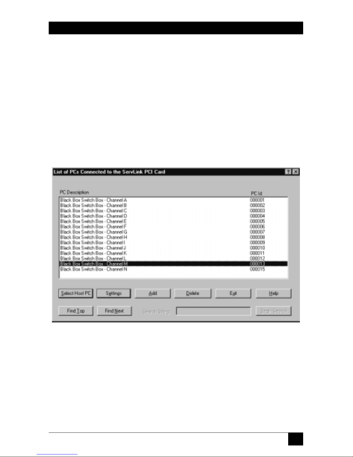
53
CHAPTER 6: The Menu System
• Control Module Configuration
Select this option to configure any Power Management Modules attached to
the ServLINK. You can force the Modules to require justification for powerrelated actions; specify the number of seconds that a computer will be off
when the power is cycled; or specify the COM port where the first
Management Module is attached to the ServLINK. See Section 6.1.3.
6.1.1 S
WITCH
PC
S
6.1.1.A The Main Dialog Box
When you select “Switch PCs” from the Switch menu, the dialog box shown in
Figure 6-4 appears. (This box is also available when you’re in Host Mode, by
selecting the Shortcut Keys tab in Host Mode Properties and clicking the “Switch
PCs” button. See Section 5.2.3.)
Figure 6-4. The Switch PCs dialog box.
In its factory-default condition, this window will contain fourteen PC descriptions,
which can be used to switch between as many as fourteen PCs connected to the
corresponding channels (CPU ports) of an attached ServSwitch Multi, ServSelect,
etc. If your system fits this description, you can use these descriptions as they are,
although you might want to rename them. If you only have a single PC connected
to the ServLINK, you’ll probably want to create a new description for it and delete
the 14 presets. If you have multiple PCs but they’re connected to some other kind
of ServSwitch (regular ServSwitch, ServSwitch Ultra, Matrix ServSwitch, ServSwitch
Wizard Pro, etc.), you’ll need to change these descriptions to match your setup, or
create new PC descriptions for them.
Page 55

54
SERVLINK™
Here’s what the components of this main box are for:
• PC Description
This column contains the name or description assigned to each computer
connected to the ServLINK system. The default descriptions are “Black Box
Switch Box - Channel [letter]”, where [letter] is a ServSwitch Multi or
ServSelect CPU-port designation from A through N.
To change the name of a given computer, highlight the existing name here,
then click the Settings button; to add a new computer description, click the
Add button. See Section 6.1.1.B for the full procedure.
• PC ID
This column contains the ID numbers that the ServLINK assigns to the
attached computers in order to keep track of them; these are used in the
ServLINK’s Event Log (see Section 6.2.9) and can’t be changed.
• Select Host PC
You can use this button to start access/control sessions with the attached PCs.
Use the arrow keys on your keyboard to move the highlight bar in the
PC Description window to a particular computer, then click “Select Host PC”
to access that computer. (Alternatively, you can just double-click the mouse on
the PC Description.) This will bring up the notice shown in Figure 6-5:
Figure 6-5. The Host Mode notice.
Page 56

55
CHAPTER 6: The Menu System
When you click OK, the ServLINK will go into “Host Mode”: The desktop of
the chosen computer will appear, with a crosshair cursor that shows your local
mouse movement as well as the regular mouse pointer that shows mouse
movement at the remote PC. (If no PC is actually attached to that port, the
screen will go dark and a “ServLINK NO VIDEO SIGNAL” message will appear.)
• Settings
Use the arrow keys on your keyboard to move the highlight bar in the
PC Description window to a particular computer, then click this button if you
want to view or change any of the ServLINK’s internal settings for that
computer. See Section 6.1.1.B.
• Add
Click this button if you want to add a new computer to the list in the
PC Description window. See Section 6.1.1.B.
• Delete
Use the arrow keys on your keyboard to move the highlight bar in the
PC Description window to a particular computer, then click this button if you
want to delete that computer from the list. An “Are you sure?” message will
appear; if you confirm the action, the computer will be deleted.
• Exit
Click this button to exit this box and return to the Main Menu.
• Help
Click this button to get on-line help for this box.
• Find Top
Click this button to initiate a ServLINK search for the first occurrence of a
Search String that you’ll specify in the list of PC Descriptions. The search
proceeds from the currently highlighted PC to the bottom of the list. This can
be very useful for finding PCs in large installations.
• Find Next
After a “Find Top” search has been successful once, click this button to have
the ServLINK search for additional occurrences of the original Search String
or for a different string.
• Search String
When you click “Find Top” or “Find Next,” this field becomes active. Type in a
string up to 45 characters long that you want the ServLINK to search the PC
Descriptions for. These searches are not case-sensitive.
• Begin Search
Click this button to start the search when you finish typing in the Search String.
Page 57

56
SERVLINK™
6.1.1.B The Settings Dialog Box
When you click the Settings button or the Add button in the Switch PCs box, the
Settings dialog box shown in Figure 6-6 appears.
Figure 6-6. The Switch PCs: Settings dialog box.
Here’s what the components of the Settings box are for:
• PC Description
Type in a unique name/description for this computer that will identify it for
all ServLINK users. We recommend that you use the same name or description,
if any, assigned to this computer in the KVM switch. Once you assign this
description, it will appear in the “PC Description” column described above.
If you got to this box by clicking “Add,” this field will be blank, waiting for
you to type in a name or description. If you got here by moving to an existing
name/description and clicking Settings, this field will contain that name/
description, highlighted and ready to be changed if necessary. You can enter
descriptions up to 40 characters long. Note that once a PC is defined, its entry
can be changed but not entirely blanked out; if you try to save these Settings
with a blank PC Description, you will receive an error message instead.
Page 58

57
CHAPTER 6: The Menu System
• Switch Box Command
This is the hotkey sequence (if any) that starts all KVM-switch commands or
puts the attached KVM switch in command mode. You need to make sure this
is designated correctly here so that the ServLINK can send the necessary
“switch to this PC” command to the KVM switch.
The factory-default setting is “Switch Box Not Applicable,” an empty
“dummy” macro suitable for systems with no KVM switch attached, or for KVM
switches that don’t use a hotkey sequence. When you pull down this menu, you
can choose any of the listed already-defined hotkey keystroke macros by
double-clicking on the macro; this sequence you choose will become the new
default sequence. (Be careful as you do this; if you accidentally choose the
wrong hotkey sequence here, PC switching through the ServLINK simply won’t
work until you correct the mistake.)
Most of the hotkey sequences used by ServSwitch family KVM switches are
listed here, including “Left Ctrl” for the switches compatible with the regular
ServSwitch, “NumLock + ‘–’” for the switches compatible with the ServSwitch
Multi, and so on. If the necessary sequence necessary for your KVM switch isn’t
in the menu, you’ll need to define it with the Create Keyboard Macro option
(see Section 6.4).
Note that if you disable switching through the KVM switch’s keyboard
commands or on-screen display (see Section 6.2.8), so that PC switching has to
handled directly through the ServLINK, this entry will be grayed out and will
say “ServLINK Ctrls XPLU [user-card] Switching.”
• Switch Box Select PC
This is the body of the switching command that the ServLINK must send to the
attached KVM switch, following the “Switch Box Command” above, in order to
select this computer. You need to make sure this is designated correctly here
so that the ServLINK can send the necessary “switch to this PC” command to
the KVM switch.
The factory-default setting is “Switch Box Not Applicable,” suitable for
systems with no KVM switch attached. When you pull down this menu, you can
choose any of the listed already-defined keystroke macros by double-clicking
on the macro; this sequence you choose will become the new default
sequence. (Be careful as you do this; if you accidentally choose the wrong
hotkey sequence here, the ServLINK will switch to the wrong PC, or not switch
at all, until you correct the mistake.)
For example, if you are giving the ServLINK the settings for the CPU
attached to port G of a solitary ServSwitch Multi, scroll down to “g - Enter.”
Here’s why: If you were typing in the command to switch to port G directly
into the ServSwitch Multi, you would first enter the command’s hotkey
sequence by pressing and holding [Num Lock], pressing and releasing the
minus [–] key, and releasing [Num Lock]—the “NumLock + ‘–’” Switch Box
Page 59

58
SERVLINK™
Command previously discussed. Then you would press and release [g] to select
the port, and finally press and release [Enter] to finish the command—which
is the “g - Enter” sequence you should select here.
Similarly, if you are setting up the CPU on port 15 in a regular ServSwitch
or compatible system, you should have selected “Left Ctrl” as the Switch Box
Command above; now choose the “15 - Enter” Select PC sequence here.
If the sequence needed for the PC you’re setting up isn’t in this list, you’ll
need to define it with the Create Keyboard Macro option (see Section 6.4).
• Video Driver File Name
This is the name of the “video driver”—actually a preferences file—that the
ServLINK will use to interpret this PC’s video output. The first time you access
this PC, the ServLINK will autodetect a group of default video settings for it,
and generate this file. These settings will probably need finer manual
adjustment; as you make and save such adjustments, the ServLINK will store
them in this driver for future use.
Under normal circumstances, you will not need to specify a different driver
for a PC. See Section 6.3 and your on-line help for more details.
• ServLINK PC ID#
This is the unique number that the ServLINK will use to keep track of this PC.
This field will be grayed out because the ID number is automatically generated
and maintained by the ServLINK and cannot be changed. (About the only
time you will need to refer to this number is when you are examining the
ServLINK’s Event Logs, in which all of the system’s computers are referred to
by their number. See Section 6.2.9.)
• OK
Click this button to save any changes you’ve made and return to the
Switch PCs box.
• Cancel
Click this button to abort any changes you’ve made and return to the Switch
PCs box.
• Help
Click this button to get on-line help for this box.
Page 60

59
CHAPTER 6: The Menu System
6.1.2 C
ONTROLMODULEPROCESSING(SERV
LINK S
YSTEM WITHPOWERMANAGEMENT
M
ODULESONLY
)
NOTE
Before activating Control Module Processing for the first time, select
Control Module Configuration (see Section 6.1.3) and specify which of
the ServLINK’s COM ports that the daisychain of Power Management
Modules is attached to. The default COM port will be COM1 if you don’t
specify a COM port; obviously, if that isn’t the correct port, the ServLINK
won’t detect the Modules at all.
For more details about the Power Management Modules, refer to
their own manual.
6.1.2.A The Main Dialog Box
When you select “Control Module Processing” from the Switch menu, the dialog
box shown in Figure 6-7 appears.
Figure 6-7. The Control Module Processing main dialog box.
This box and the affiliated Settings box (see Section 6.1.2.B) are for administering
attached Power Management Modules. (If you don’t have Power Management
Modules installed, they’re irrelevant.) As soon as it displays the box, the ServLINK
immediately polls the COM port specified in Control Module Configuration (see
Section 6.1.3) for an attached daisychain of Power Management Modules. (If
you’ve installed a Management Module that controls power to the ServLINK itself,
it’s attached differently and can’t be accessed from here. It only responds to dial-in
reboot requests—see Section 6.6.2.) The polling process takes about one second
per Module. During the polling process, the ServLINK determines if (1) new
Power Management Modules have been added to the chain, (2) Modules have
Page 61

60
SERVLINK™
been deleted from the chain, or (3) the physical positions of any Modules have
changed, since the last time the daisychain was polled. If any of these events have
occurred, applicable messages are displayed on the screen at the end of the polling
process and the changes are recorded in the ServLINK event log. Also, any active
Power Management Modules are cleared (deactivated) during the polling process,
which puts the daisy-chain into “pass-through mode.”
If no Power Management Modules are detected during the polling process, an
appropriate message is displayed, and the Activate, Settings, and Pass Through
buttons on the right of the window are grayed out. When this occurs, it is likely the
wrong COM port has been specified, another device in the ServLINK (often the
mouse) is interfering with access to the COM port, or the daisychain is not
properly installed.
Note that when ServLINK user security is enabled and the current user doesn’t
have access rights to all of the Power Management Modules in a daisychain, then
only those Modules for which the user has access rights appear here in the Module
list. For information about setting users’ access rights to the Power Management
Modules, see Section 6.2.1.
Here’s what the components of the main Control Module Processing box are for:
• Pos
This column lists the “position numbers” of the Power Management Modules
in your Module daisychain. The “first” Module—the one controlling power to
the first computer, and attached directly to the serial port of the ServLINK
itself—is number 001. The second one, attached to the first’s IN port, is
number 002, and so on.
• Power
This column indicates whether the Module is supplying power to the device
it’s attached to (ON) or not (OFF).
• Description of Device...
This column lists any description entered for the device attached to this
Module in the matching field in the “Control Module Processing: Settings”
window (see Section 6.1.2.B).
• Activate
Highlighting an entry and selecting this option will allow you to activate the
selected Power Management Module, so that it’s ready to receive commands or
data from the ServLINK. Only one Module can be active at a time.
Page 62

61
CHAPTER 6: The Menu System
• Settings
Highlighting an entry and selecting this option will bring up the “Control
Module Processing: Settings” window (see Section 6.1.2.B), at which you can
cause this Power Management Module to turn its device ON or OFF or reboot
it, or set up conditions under which this will happen automatically.
• Pass-Through
Selecting this option will clear any active Power Management Module and
allow serial data to pass through to and from any “pass-through device” you’ve
installed at the end of the Power Management Module daisychain (see step 5
in Section 3.1.7.B).
• Repoll
Selecting this option will cause the ServLINK to recheck the currently specified
COM port for attached Power Management Modules.
• Exit
Click this button to return to the Main Menu.
• Help
Click this button to get on-line help for this box.
• Configure
Selecting this option will bring up the Control Module Configuration dialog
box (see Section 6.1.3), at which you can change some of the ServLINK’s
configuration options that apply to Power Management Modules.
Page 63
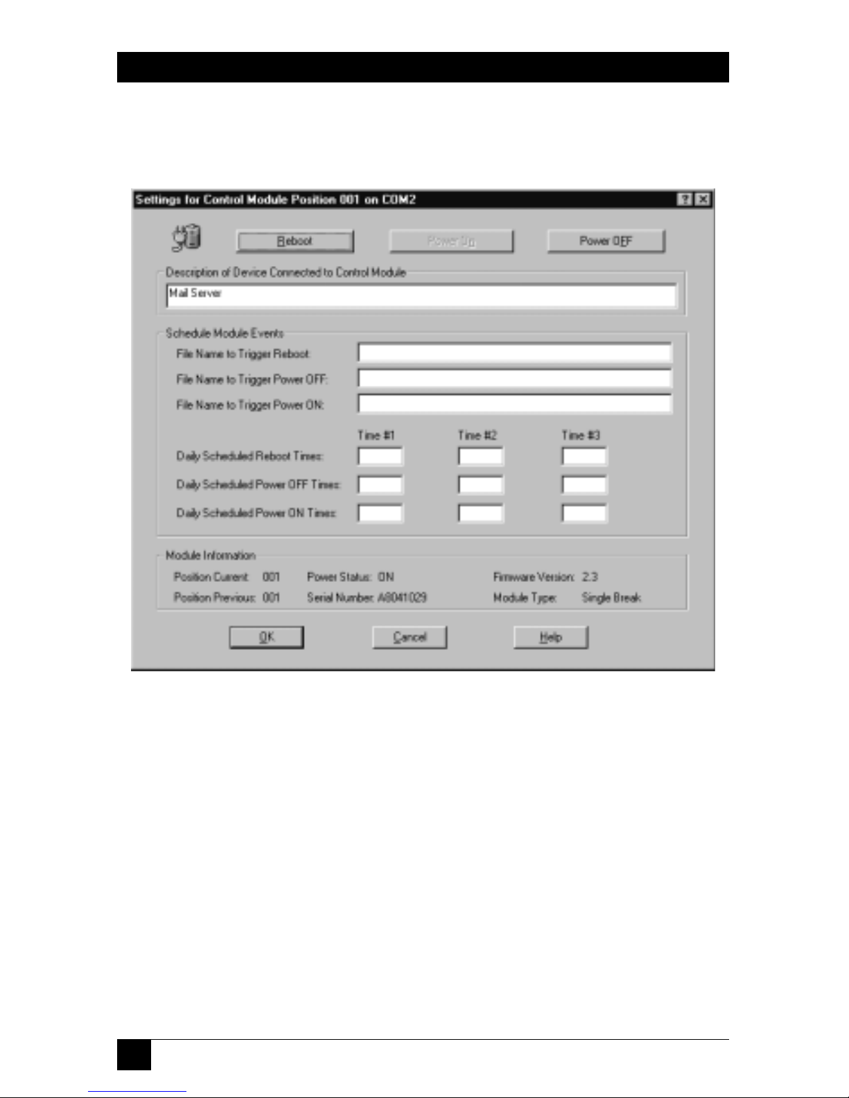
62
SERVLINK™
6.1.2.B The Settings Dialog Box
When you click “Settings” at the Control Module Processing box, the dialog box
shown in Figure 6-8 appears.
Figure 6-8. The Control Module Processing: Settings dialog box.
Here’s what the components of the “Control Module Processing: Settings” box are
for:
• Reboot
Click this button to reboot the PC or other device attached to this Power
Management Module. If “Require Reasons for Power OFF actions” is checked
in the Control Module Configuration window (see Section 6.1.3), you will be
required to give a reason for doing this.
• Power ON
Click this button to turn ON power to the PC or other device attached to this
Power Management Module. (If the power is already ON, this option will be
grayed out.) If “Require Reasons for Power ON actions” is checked in the
Control Module Configuration window (see Section 6.1.3), you will be
required to give a reason for doing this.
Page 64

63
CHAPTER 6: The Menu System
• Power OFF
Click this button to turn OFF power to the PC or other device attached to this
Power Management Module. (If the power is already OFF, this option will be
grayed out.) If “Require Reasons for Power OFF actions” is checked in the
Control Module Configuration window (see Section 6.1.3), you will be
required to give a reason for doing this.
• Description of Device...
You can enter a description in this field up to 40 characters long for the PC or
other device attached to the Power Management Module. (Unfortunately,
there is not currently any way to pull down entries from the ServLINK’s main
PC Description field into this field.)
• Schedule Module Events
In these fields, you can specify two things that can cause the ServLINK to signal
the Power Management Module to reboot, power OFF, or power ON the
attached PC or other device:
– In the “Daily Scheduled...” fields, you can enter as many as three separate
clock times (in military-time format) at which events will occur daily. For
example, you can set the Module to power ON a PC at 0600 (6 a.m.) at the
start of each day, reboot it at 1730 (5:30 p.m.), and power it OFF every night
at 0200 (2 a.m.).
– In the “Files to Trigger...” fields, you can enter the full pathnames of “trigger
files” that the ServLINK will watch for. When the files appear, the ServLINK
will delete them, then tell the associated Module to perform the specified
action (power ON, power OFF, or reboot the attached device). For
examples and more details, see the Module’s own manual.
• Module Information
Tells you at a glance which position in the daisychain this Module holds, which
other position (if any) it was in most recently, whether it is currently providing
power (ON) or not (OFF), and its serial number, firmware version, and type.
• OK
Click this button to save any changes you’ve made and return to the main
Control Module Processing box.
• Cancel
Click this button to abort any changes you’ve made and return to the main
Control Module Processing box.
• Help
Click this button to get on-line help for this box.
Page 65

64
SERVLINK™
6.1.3 C
ONTROLMODULECONFIGURATION(SERV
LINK S
YSTEM WITHPOWERMANAGEMENT
M
ODULESONLY
)
NOTE
For more details about the Power Management Modules, refer to their
own manual.
When you select “Control Module Configuration” from the Switch menu, or when
you click “Configuration” at the Control Module Processing box, the dialog box
shown in Figure 6-9 appears.
Figure 6-9. The Control Module Configuration dialog box.
This box is for configuring some of the ServLINK’s systemwide Power Management
Module settings. (If you don’t have Power Management Modules installed, it’s
irrelevant.) Here’s what the components of this box are for:
• Require Reasons for Power OFF Actions
When this box is checked, users are required to provide a reason whenever
they reboot or power down any device connected to a Power Management
Module from the “Control Module Processing: Settings” window (see
Section 6.1.2.B). The justification may contain up to two lines of 50 characters
per line, and is saved in the ServLINK’s event log.
Page 66

65
CHAPTER 6: The Menu System
• Require Reasons for Power ON Actions
When this box is checked, users are required to provide a reason whenever
they power on any device connected to a Power Management Module from the
“Control Module Processing: Settings” window (see Section 6.1.2.B). The
reason entered may contain up to two lines of 50 characters per line, and is
saved in the ServLINK event log.
• Reboot Delay in Seconds
Use this option to configure the number of seconds that power is temporarily
shut off to the device connected to a Power Management Module when the
Reboot option is selected at the “Control Module Processing: Settings” window
(see Section 6.1.2.B). The default setting is 20 seconds; possible settings range
from 10 to 999 seconds (over 16 minutes).
• Module Daisy Chain COM Port
This option is used to designate which of the ServLINK’s COM ports the Power
Management Modules are attached to. If there’s only one Module attached to
the ServLINK, this option only needs to be be set once. Management Modules
must be installed on COM1 or COM2 (or, if you install extra ports, COM3 or
COM4), and they cannot share an IRQ with any other device. You may select
the “AUTO” option if you want the ServLINK to automatically scan COM1
through COM4 to locate the Module daisychain. Once you make this
selection, the chosen COM port will appear in the header bar of the Control
Module Processing windows.
CAUTION!
In some cases, automatically scanning the COM ports with the AUTO
setting could possibly interfere with other devices and/or lock up the
ServLINK—some mice in particular don’t react well to being queried.
• OK
Click this button to save any changes you’ve made and return to the Main
Menu.
• Cancel
Click this button to abort any changes you’ve made and return to the Main
Menu.
• Help
Click this button to get on-line help for this box.
Page 67
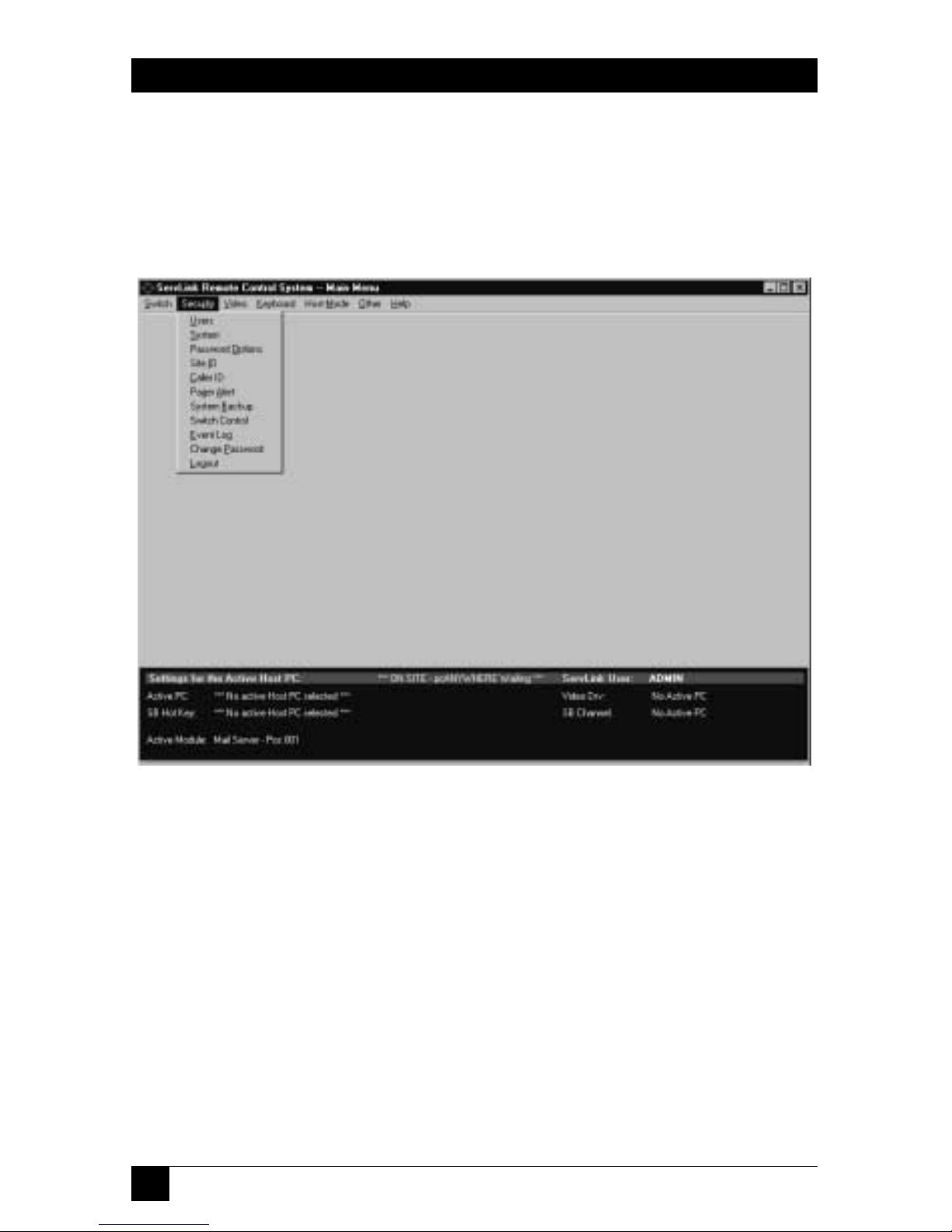
66
SERVLINK™
6.2 The Security Menu
The second primary option available under the Main Menu is “Security.” When
you pull down the Security Menu, you’ll see eleven selections, as shown in
Figure 6-10. These eleven options are described in the corresponding subsections
on the following pages.
Figure 6-10. The Security menu.
Page 68

67
CHAPTER 6: The Menu System
6.2.1 U
SERS
ServLINK offers multiple ways to protect your system from unwanted access. Before
you enable any other security, you must first define users. To do this, take these steps:
1. Pull down the Security menu and select Users. The dialog box shown in
Figure 6-11 will appear.
Figure 6-11. The Users dialog box.
2. Click “Enable Security.” (If you also click “Use Windows User Authentication,”
users will log in to the ServLINK system by logging into Windows NT.)
3. Click the “Add User” button. The dialog box shown in Figure 6-12 on the
next page will appear. (At any time later, you can change this user’s settings
by highlighting their entry and clicking “Change User” here, or simply delete
them from the system by highlighting their entry and clicking “Delete User.”)
4. Enter a User Name of up to 25 characters. User names are not case sensitive.
ServLINK does not allow duplicate names. If you have “Use Windows User
Authentication” checked in the main Users box, make very sure that the name
you type in here is identical to the username entered for Windows NT.
5. Enter a password for this user. (Passwords are required and may be up to
15 characters long.) Re-enter the password to confirm it.
Page 69

68
SERVLINK™
Figure 6-12. The Add Users dialog box.
6. You will then need to decide on certain rights for the new user. They may be
selected by clicking the check box beside each item:
Supervisor Rights
When this box is checked, the user has full access to all ServLINK system
settings, including the ability to enable and disable security, add and delete
users, and change passwords. If this box is not checked, the user is considered
to be a “standard” user.
Force Password Change
This option forces the user to change their password the next time that they
log in. This box is normally only selected when a new user is added or a current
user forgets their password. In these cases, the Administrator assigns the user
a temporary password and they are forced to change it when they log in.
User Locked Out
When this box is checked, the user in question cannot log in to the ServLINK
system. It is checked automatically whenever a user exceeds a specified
number of Login attempts without entering a valid password.
Page 70

69
CHAPTER 6: The Menu System
7. Add Non-Supervisor Access rights. (If the user has Supervisor access, these
boxes will be grayed out.) To set Host PC access rights, click the “View/
Modify...” button; the dialog box shown in Figure 6-13 appears. Simply create
a list of the PCs that this user will be allowed to access. (By default, access is
“approved” [YES] for all computers; “deny” [change to NO] any computers
this user should not access.)
When you finish this process, click “OK” to save your changes and return
to the Add Users box.
Figure 6-13. The Host PC Access Rights dialog box.
8. If your system includes Power Management Modules: If necessary, restrict this user’s
access to any Module(s) by clicking the Add button in the Control Module
Access Rights area. Type in the three-digit number of any Module you want to
make off-limits to this user in the box that pops up, and that number will appear
in the Pos column of the “Deny access” area to the right. Keep typing in numbers
until the “Deny” list for this user is complete. (Remember that position “001”
is the first Module in the chain—the Module attached to the ServLINK’s serial
port that controls power to the first PC, not the Module that controls power to
the ServLINK itself—and “002” is the second Module in the chain, etc.)
To restore a user’s access to a Module later, highlight the Module’s entry
in the “Deny” list and click the Delete button. (Both the Add and Delete buttons
will always be grayed out for supervisors, who always have access to all Modules.)
9. Click OK to return to the Users box; there should now be an entry for this
user in the users list.
10. Repeat steps 3 through 9 for all the users in your system. When you’re
finished, click OK to return to the Main Menu.
Page 71

70
SERVLINK™
6.2.2 S
YSTEM
When you pull down the Security menu and select System, the dialog box shown in
Figure 6-14 appears.
Figure 6-14. The System Security dialog box.
At this box, you can configure the ServLINK with system-security options for all
users. These options include:
• Enable Limit on LOGIN Attempts
This sets the number of failed login attempts that a user may make before
being locked out of the system. Once a user is locked out, only a supervisor
may re-enable their account. The system default is 3 attempts. You can specify
any number from 0 to 99 attempts (a setting of zero will deactivate the option).
• Enable Password Expiration
When checked, this option specifies how many days can pass before a user is
forced to change their password. The system default is every 30 days. You can
specify any number from 0 to 999 days (a setting of zero will deactivate the
option).
Page 72

71
CHAPTER 6: The Menu System
• Enable Minimum Password Length
This option sets the minimum length for passwords to the specified number of
characters. (Even if this setting is disabled or set to zero, passwords must be at
least one character long—no “null-string passwords” are allowed under any
circumstances.) Passwords may be as long as 15 characters; the default length
is 5 characters.
• Remote Session Beep Interval
This feature is used to alert the host site when someone remotely accesses the
ServLINK. When this feature is enabled, the ServLINK will beep or play a
.WAV file at a specified interval between 0 and 99 seconds. The default value is
10 seconds; setting this option to zero disables this option. (No matter how this
option is set, the ServLINK will always sound three beeps when it is powered
on.)
• Enable Inactivity Timer
The Inactivity Timer, when enabled, monitors user activity through keyboard
input and mouse-click menu selections (but not simple mouse movement). If
no activity is detected within the time specified here (default is 10 minutes),
you can set the ServLINK to either automatically log the user out or switch the
user to Host Mode.
Page 73

72
SERVLINK™
6.2.3 P
ASSWORDOPTIONS
When you pull down the Security menu and select Password Options, the dialog
box shown in Figure 6-15 appears.
Figure 6-15. The System Security dialog box.
• Password may not be the same as the user’s login ID
When this box is checked, the User ID may not be used as a password. Note
that passwords are case sensitive, so a case variation on a User ID will be
accepted.
• Password may not contain spaces (blanks)
When this option is selected, users may not include any spaces in their
password.
• Password may not have more than 2 consecutive identical characters
When this box is checked, users may not enter passwords with more than two
consecutive characters. For example, the password “aaa” would not be
accepted.
• Passwords may not be reused by a user for 10 cycles
When this box is checked, once a password expires or is changed, passwords
must be changed at least 10 times before that password may be reused.
• Passwords must contain at least 1 alphanumeric and 1 numeric character
When this option is selected, a user’s password must contain at least one
number and one letter.
When you’re finished, click “OK” to save your changes or “Cancel” to abort them.
Page 74
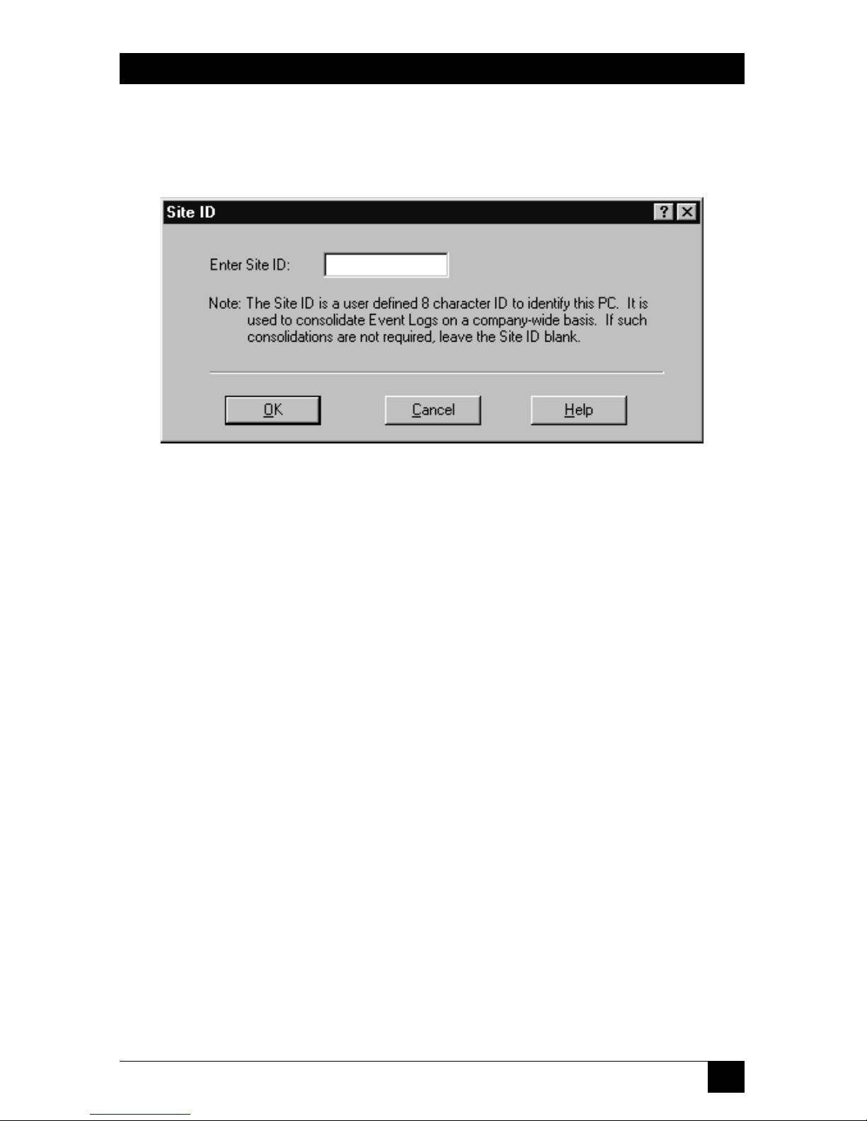
73
CHAPTER 6: The Menu System
6.2.4 S
ITE
ID
When you pull down the Security menu and select Site ID, the dialog box shown in
Figure 6-16 appears.
Figure 6-16. The Site ID dialog box.
The Site ID menu option allows you to assign your ServLINK a site name up to
8 characters long. This name must be unique, and cannot be used by any other PC
in the system.
The Site ID permits each event log stored within the remote PCs in a ServLINK
system to be consolidated into a central system-wide event log file. The Site ID
identifies each individual PC in the system.
Page 75

74
SERVLINK™
6.2.5 C
ALLER
ID
When you pull down the Security menu and select Caller ID, the dialog box shown
in Figure 6-17 appears.
Figure 6-17. The Caller ID dialog box.
• Optional Caller ID Service Installed on Modem Phone Line
If you have Caller ID service on the phone line that the ServLINK’s modem is
on, and you want to implement Caller-ID-based security, make sure this box is
checked.
• Caller ID Required to Access ServLINK PC Via Modem
If this box is checked, the ServLINK’s modem won’t answer any calls from
phone lines with Caller ID blocked.
Page 76
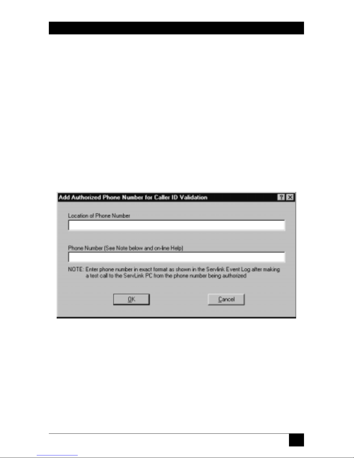
75
CHAPTER 6: The Menu System
• Caller ID Required from List Below to Access ServLINK PC
When selected, this option restricts ServLINK access to numbers that are
specified in an administrator-maintained list. When this option is activated,
only users specified in the list can call in. There are some instances where
Caller ID may not properly transmit the number; it’s important to place test
calls from each number when it is entered into this list.
When you select this, the List of Authorized Caller Locations becomes
active, as well as the three buttons below it:
– Add
Click this button to bring up the Add Caller ID dialog box shown in
Figure 6-18: Enter “Location of Phone Number” (a brief description of
where the caller will be calling from) and the “Phone Number” itself. The
phone number must include an area code; enter it exactly as it appears on
the Caller ID unit’s display, or exactly as shown in the ServLINK’s Event Log
after a test call has been placed to the ServLINK from that phone.
Figure 6-18. The Add Caller ID dialog box.
– Change
Highlight an Authorized Caller Location and click this button to change the
Location of Phone Number or the Phone Number itself.
– Delete
Highlight an Authorized Caller Location and click this button to delete it
from the list.
When you’re finished, click “OK” to save your changes or “Cancel” to abort them.
Page 77

76
SERVLINK™
6.2.6 P
AGERALERT
When you pull down the Security menu and select Pager Alert, the dialog box
shown in Figure 6-19 appears.
Figure 6-19. The Pager Alert dialog box.
ServLINK may be configured to issue pager alerts to one or more pagers when
ServLINK User Security is enabled and a user fails to successfully login with the
allowed number of password attempts.
The Pager Alert window allows enabling or disabling the Pager Alert feature and
adding, changing, or deleting pagers from the alert list.
To enable Pager Alerts, you must first have an external modem connected to the
data port of the Access Control card. Next, click the box “Enable Pager Alerts” box.
You will then be able to Add, Change, or Delete persons who are to receive pager
alerts.
Page 78
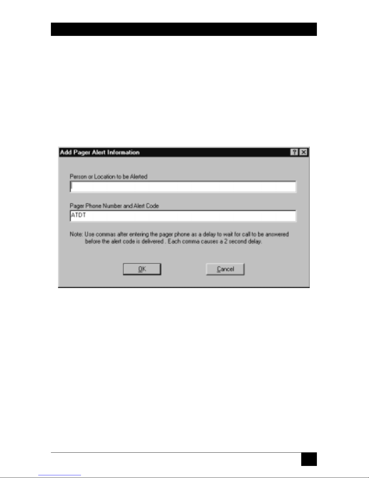
77
CHAPTER 6: The Menu System
• Add
When you click this button, the dialog box shown in Figure 6-20 will appear.
Enter a brief description of the “Person or Location to be Alerted,” then the
“Pager Phone Number and Alert Code.” This number should be preceded by
the modem command ATDT.
If you wish, you can enter an alert code after the number that is to be
paged. To do this, enter several commas after the pager number—each one
will cause a two-second delay, to give time for the paging system to pick up—
and then a numeric alert code that is meaningful to the person receiving the
page.
Figure 6-20. The Add Pager Alert dialog box.
• Change
To change a user’s Location or Pager settings, just highlight their entry and
select this option.
• Delete
To delete a user from the list, just highlight their entry and select this option.
• Cancel
Click this button to abort your changes and return to the Main Menu.
• OK
Click this button to save your changes and return to the Main Menu.
Page 79
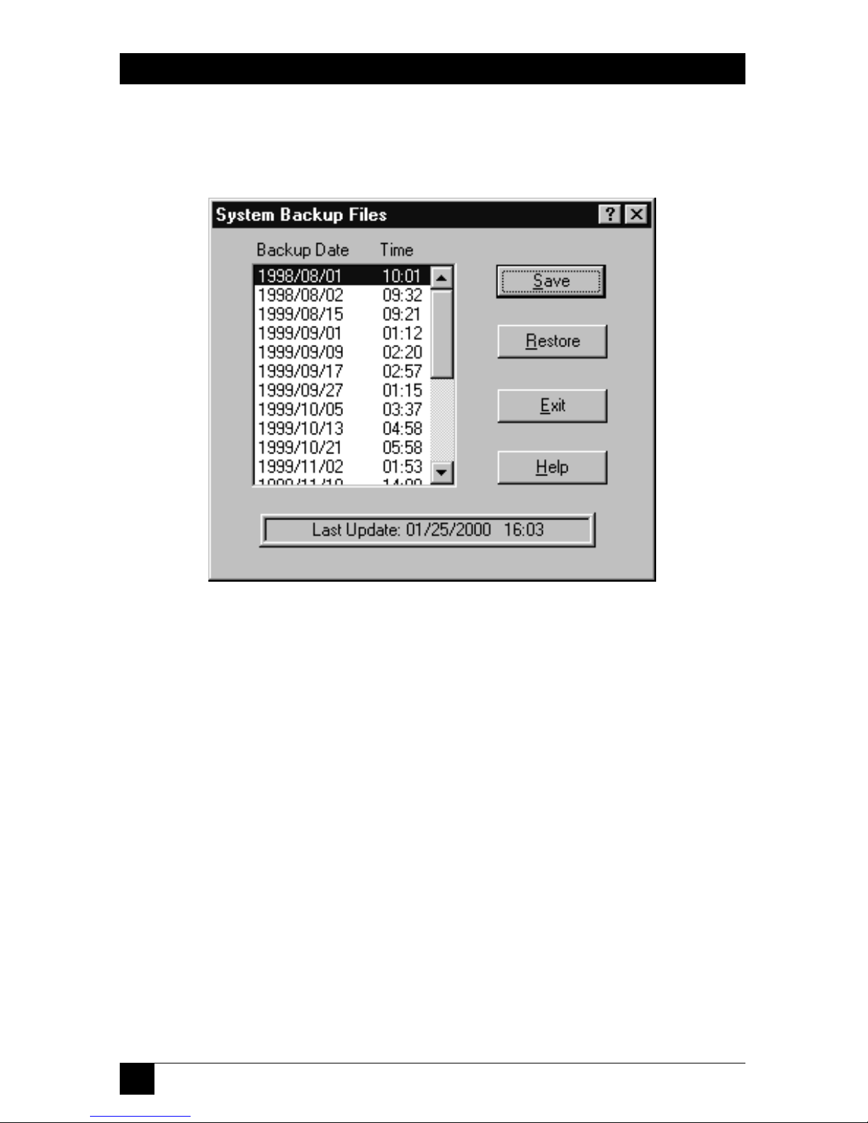
78
SERVLINK™
6.2.7 S
YSTEMBACKUP
When you pull down the Security menu and select System Backup, the dialog box
shown in Figure 6-21 appears.
Figure 6-21. The System Backup dialog box.
This option allows a user to encrypt and save the current status of a ServLINK
configuration or restore a previously saved configuration. When changes to the
ServLINK configuration are made, they are not saved until the Save button in this
menu is clicked or the ServLINK application’s processing ends normally (when you
select Quit from the Other menu—see Section 6.6.7).
Here’s what the components of this box are for:
• Backup Date/Time
This list box records all backup files saved by ServLINK during the last year.
Each time a ServLINK menu option is selected, ServLINK checks the current
date against this list and automatically backs up the configuration if more than
seven days have elapsed since the last backup.
• Save
Click this button to save the current ServLINK configuration.
Page 80

79
CHAPTER 6: The Menu System
• Restore
Highlight a backup file in the list and click this button to restore the
ServLINK’s configuration from that file.
• Exit
Click this button to return to the Main Menu.
• Help
Click this button to get on-line help about the System Backup function.
• Last Update
The date and time of the most recent save.
Page 81

80
SERVLINK™
6.2.8 S
WITCHCONTROL(SERV
LINK A
TTACHED TOSERVSWITCHMULTIONLY
)
When you pull down the Security menu and select Switch Control, the dialog box
shown in Figure 6-22 appears.
Figure 6-22. The Switch Control dialog box.
This box is only meaningful if the ServLINK is attached to a regular Universal User
Interface Card (KV2500C) with a firmware revision more recent than 9/25/99
installed in a ServSwitch Multi. (This User Card is the type with no on-screen
display, referred to internally by the ServLINK and the ServSwitch Multi as an
“XPLU.”)
In this situation, for additional security, you can click the top checkbox to
disable switching between PCs from the ServLINK’s keyboard. While keyboard
switching is disabled, the normal keyboard macros that appear in the PC Settings:
Switch Box Command list (see Section 6.1.1.B) disappear and are replaced by “SL
Ctrls XPLU Switching”: The ServLINK uses a special protocol, rather than
keyboard commands, to switch between PCs on the ServSwitch Multi system. This
makes it virtually impossible for a non-supervisor user to access any computer they
wouldn’t normally have access to.
You can now go a step further and click the bottom checkbox; this causes the
ServLINK to look for a particular file in order to define PC switching for such
users. This is intended for use at sites with sophisticated software-based security
controls; for more information, please consult on-line help for this function.
Page 82
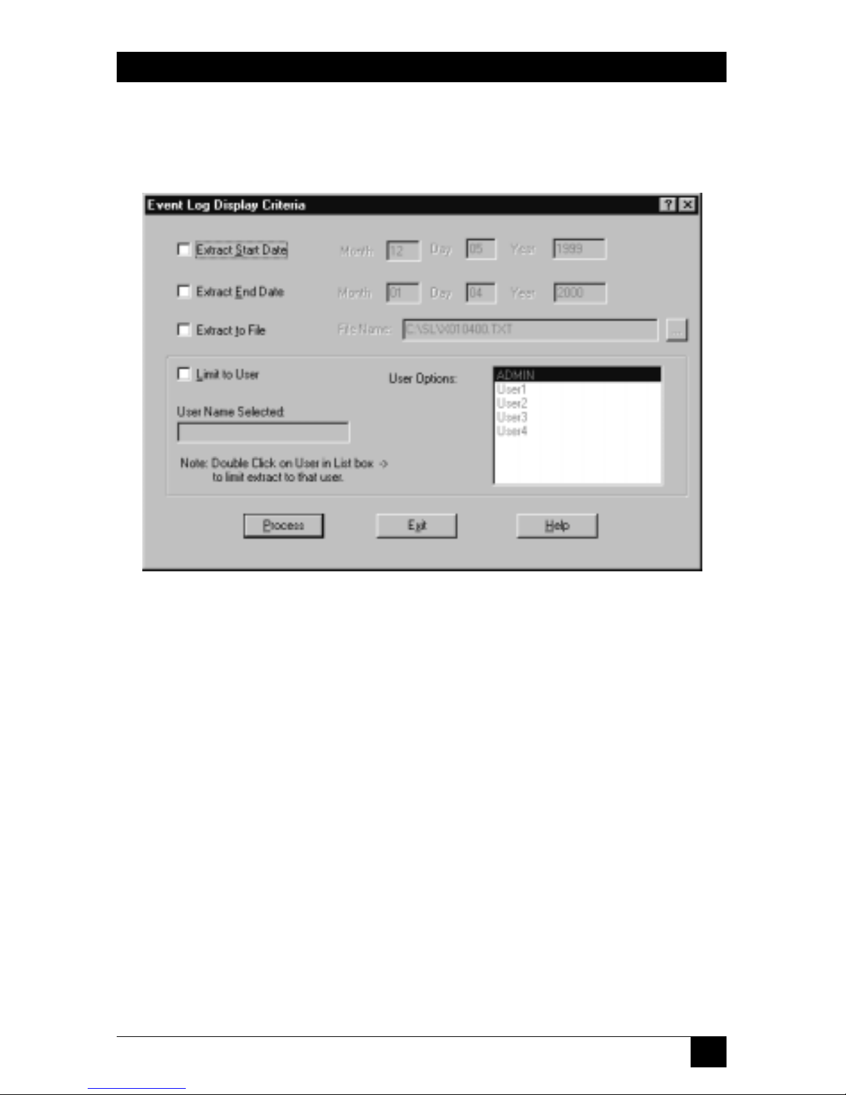
81
CHAPTER 6: The Menu System
6.2.9 E
VENTLOG
When you pull down the Security menu and select Event Log, the dialog box
shown in Figure 6-23 appears.
Figure 6-23. The Event Log dialog box.
This option permits viewing the ServLINK event log. This log contains date- and
time-stamped entries that track all aspects of user access to ServLINK Host PCs as
well as changes made by users to the system configuration.
This menu option is only accessible if security is disabled or the user has
supervisor access rights.
Before extracting the event log, you might want to enter display criteria, in order
to narrow the focus of the inquiry so you don’t have to sift through immense
numbers of records. (The event-log report can contain as many as 20,000 of them.)
Do this by clicking any of the four checkboxes in this dialog box and specifying
those criteria:
• Extract Start Date
This is the date that you would like the event-log report to start with. If this
checkbox isn’t checked, the report will start at the beginning of the log.
Page 83

82
SERVLINK™
• Extract End Date
This is the date that you would like the event-log report to end with. If this
checkbox isn’t checked, the report will end with the last entry in the event log.
• Extract to File
This option saves the event-log report to a specified file. Click this checkbox
and enter the pathname of the file.
• Limit to User
This option extracts the log information for a specific user. Only that user’s
access to the ServLINK unit will be reported. To use this option, choose the
username from the User Options list to the right; that username will then
appear in the User Name Selected field.
When you’ve finished selecting the constraints for your report, click the “Process”
button to generate it. Unless you’ve directed the output to a file, the report will
appear in a window as shown in Figure 6-24:
Figure 6-24. The Event Log report.
Click the “X” close-box in the upper right to close the report and return to the
Event Log box. Then click “Exit” to return to the Main Menu. At any time, you can
click the Help button for on-line help about the Event Log.
Page 84
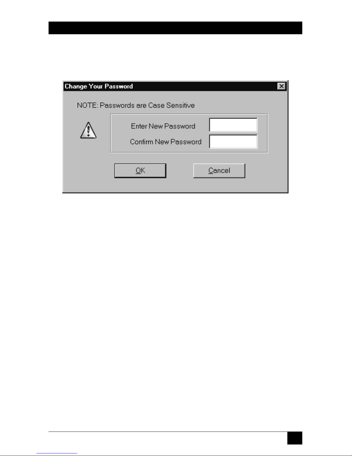
83
CHAPTER 6: The Menu System
6.2.10 C
HANGEPASSWORD
When you pull down the Security menu and select Change Password, the dialog
box shown in Figure 6-25 appears.
Figure 6-25. The Change Password dialog box.
Here, any user who has successfully logged in can change their password as
desired.
6.2.11 L
OGOUT
When you pull down the Security menu and select Logout, a dialog box will pop
up asking if you’re sure; click “OK” or “Cancel.” If you click “OK,” you are logged
out of the ServLINK application. The screen will be obscured by the Black Box
“splash screen” and the login window, and that’s how things will stay until you or
another user logs in.
Page 85
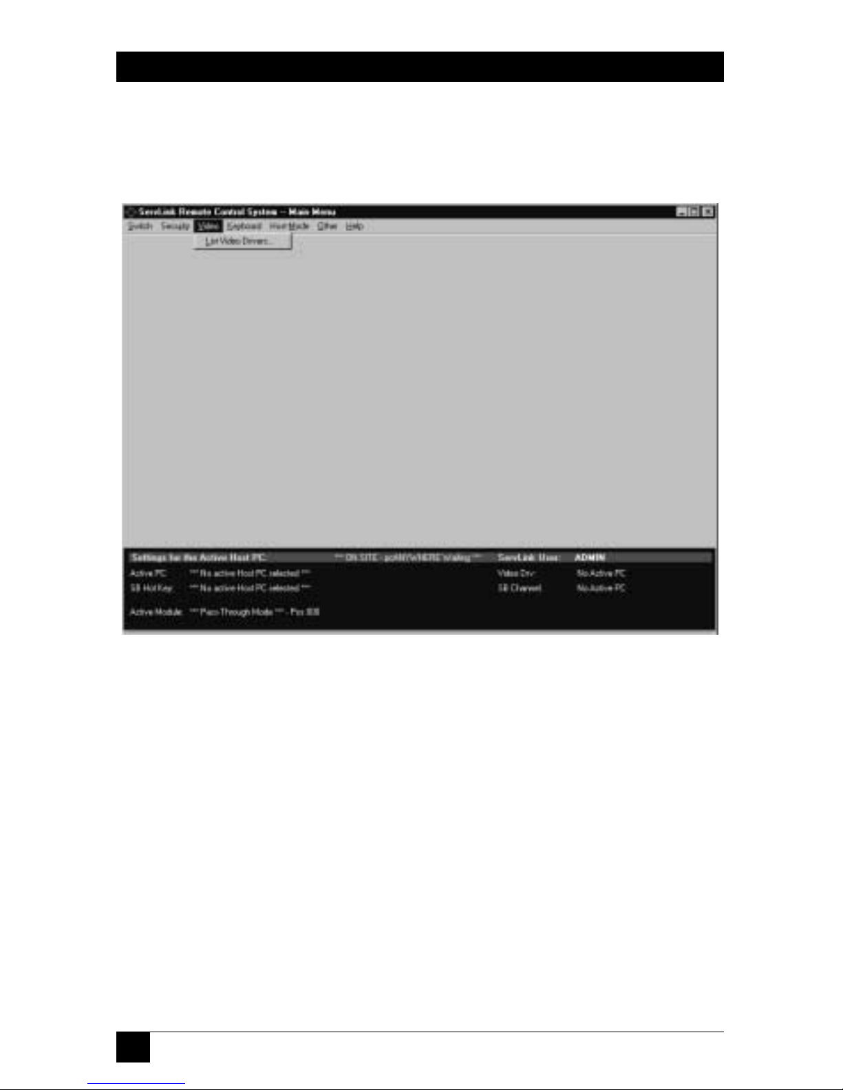
84
SERVLINK™
6.3 The Video Menu: List Video Drivers
The third primary option available under the Main Menu is “Video.” When you
pull down the Video Menu, you’ll see a single selection, as shown in Figure 6-26.
Figure 6-26. The Video menu.
Page 86

85
CHAPTER 6: The Menu System
When you select “List Video Drivers,” the dialog box shown in Figure 6-27 appears.
Figure 6-27. The List Video Drivers dialog box.
This is a list of the “video drivers” (preferences files) that the ServLINK has stored
for the ServLINK’s active Host PC. The ServLINK uses these “drivers” to determine
how best to display the video output from the attached PCs. Usually there will only
be one video driver per PC. This list includes each driver’s filename, date and time
of last change/save, and host PC.
You can highlight a driver and click the Select button to choose it for the active
PC, or click Delete to delete the file. You can also click Update to have the
ServLINK update the list of available drivers for this PC. Click Exit to return to the
Main Menu, or click Help for on-line help on the Video Drivers List.
Under normal circumstances, almost the only situation in which you’ll need to
choose a different driver for a PC is if (a) you run multiple software programs on
the PC and (b) the programs radically differ from each other in their video output.
You should almost never need to delete a driver. In general, these video-driver
options are mostly intended for testing and for very specialized applications; we
recommend that you avoid using them.
Page 87
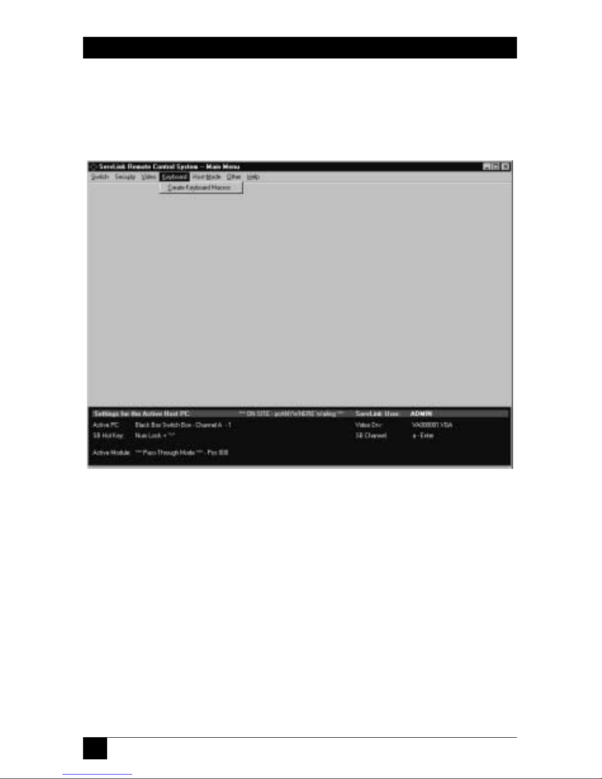
86
SERVLINK™
6.4 The Keyboard Menu: Create Keyboard Macros
The fourth primary option available under the Main Menu is “Keyboard.” When
you pull down the Keyboard Menu, you’ll see a single selection, as shown in
Figure 6-28.
Figure 6-28. The Keyboard menu.
Using the Create Keyboard Macros option, you can add, view, modify, and delete
ServLINK keyboard macros. A macro is a sequence of keyboard keypresses and key
releases that form a command; when you trigger such macros, the ServLINK sends
the command sequences to the attached PC or KVM switch to cause it to do things.
Aside from the fact that it’s quicker to press one key or to click the mouse than it
is to press several keys, sometimes macros are necessary for the ServLINK system. For
example, if you’re in Host Mode and the software running on the selected Host PC
has crashed, you might want to send [Ctrl][Alt][Del] to that PC to terminate the
program. But if you simply press those keys on the ServLINK’s keyboard, the
ServLINK itself will receive and process them. To get around this difficulty, you can
open Create Keyboard Macros, select predefined macros such as “Ctrl+Alt+Del” (or
create and then select new macros for your application), and have the ServLINK
send the corresponding keystrokes to the attached PC or KVM switch without your
having to worry about the ServLINK intercepting.keystrokes that aren’t meant for it.
Page 88
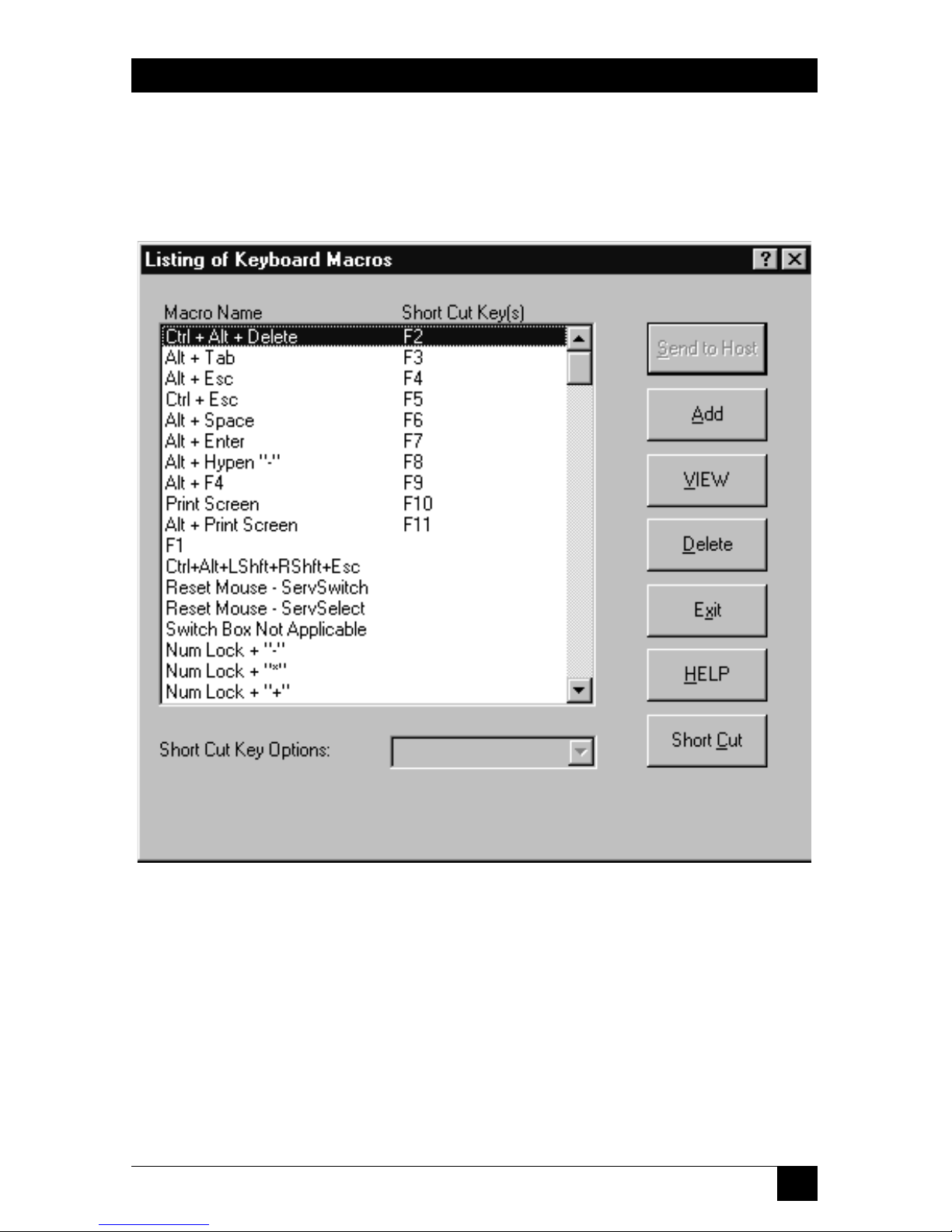
87
CHAPTER 6: The Menu System
6.4.1 THEM
AINDIALOGBOX
When you select Create Keyboard Macros, the dialog box shown in Figure 6-29
appears. (You can also bring up this box in Host Mode by pressing function key
[F12].)
Figure 6-29. The main Keyboard Macro dialog box.
The components of this dialog box are described on the following two pages.
Page 89

88
SERVLINK™
• Macro Name
This column of the main Keyboard Macro dialog box lists the currently
available macros by name. For most of the predefined macros that the
ServLINK ships with, the name consists of an “additive list” of the keys being
pressed and released (“Ctrl+Alt+Del,” for example). Other macros that
perform very specific functions are named after that function (“Reset Mouse ServSelect,” for instance). Feel free to use whatever naming convention you
find most useful as you create new macros.
There are two particular macros you should be aware of:
– “Switch Box Not Applicable” is an empty “dummy” macro that can be
selected for the Switch Box Command in the PC Settings dialog box when
the ServLINK isn’t attached to a KVM switch, or when the KVM switch
doesn’t use a hotkey sequence—see Section 6.1.1.B.
– “Reset Mouse - ServSwitch” is misnamed; it contains the mouse-reset
command for the ServSwitch Multi, not the regular ServSwitch.
• Short Cut Key(s) column
This column lists any “shortcut keys” assigned to any of your macros. Some
sequences of keystrokes, especially those that involve Windows operatingsystem functions, are liable to be used so often that you want to be able to send
them with a single keypress instead of going through this menu option all the
time. So the ServLINK software assigns shortcut keys—some of the function
keys at the top of your keyboard—to several of these macros. Pressing a
shortcut function key on your keyboard while you’re in Host Mode will cause
the ServLINK to send the corresponding macro to the Host PC.
You can assign shortcut keys to macros, or clear shortcut-key assignments, by
clicking the Short Cut button (see the next page).
• Send to Host
When you bring up this dialog box in Host Mode, clicking this button causes
the ServLINK to send the selected macro to the currently active Host PC.
When you access this box through Menu Mode, this button is grayed out.
• Add
If you want to add a new macro, click this button to open the Add Keyboard
Macro dialog box; see Section 6.4.2.
• View
If you want to see exactly which keypresses and key releases make up a given
macro, highlight that macro and click this button to open the View (List
Keyboard Press/Release) dialog box; see Section 6.4.3.
Page 90

89
CHAPTER 6: The Menu System
• Delete
If you want to delete an existing macro from the list, highlight that macro and
click this button to erase it.
• Exit
Click this button to close this box and return to the Main Menu.
• Help
Click this button to get on-line help for this box.
• Short Cut button, Short Cut Key Options field
If you want to assign a shortcut key to a macro—see Short Cut Key(s) on the
previous page—or to clear a shortcut-key assignment, highlight that macro and
click the Short Cut button. If the macro currently has any shortcut key(s)
assigned to it, those will appear in the Short Cut Key Options field; otherwise,
the word “None” will appear in that field. Clicking the down-arrow button to
the right of the Short Cut Key Options field will cause a menu of all of the
available shortcut keys to appear below the field; drag the highlight to the
key(s) you want, or to “None” if you want to clear the shortcut assignment (so
that there won’t be any shortcut keys for the macro).
The function keys [F2] through [F11] are the only keyboard keys that can be
used as shortcut keys. ([F1] triggers the on-line help system, while [F12] brings
up this dialog box in Host Mode.) When the ServLINK ships from the factory,
these shortcuts are all already assigned to important Windows keystroke
sequences that can’t be sent to an attached PC directly from your keyboard. If
you find that there are certain other macros you use much more often than
those with preassigned shortcuts, clear the preassigned shortcut keys and
assign them to the macros that need them.
Page 91

90
SERVLINK™
6.4.2 THEADDD
IALOGBOX
When you click the Add button in the main Keyboard Macros box, the dialog box
shown in Figure 6-30 appears:
Figure 6-30. The Add Keyboard Macro dialog box.
Here’s what the components of this dialog box are for:
• Macro Description
Enter a name or description here for the macro you are adding: for example,
“Ctrl+q” or “Quit” for a “quit program” sequence that consists of “press and
hold [Ctrl], press [q], release [q], release [Ctrl].” (You can’t successfully add a
macro unless you give it a description.) Once you add the macro, this
description will appear in the Macro Name column in the main Keyboard
Macro dialog box (see Section 6.4.1).
• Double Click for Key Press
Each keyboard-command sequence begins with a single keypress; even
sequences in which multiple keys are to be pressed at the same time can
actually start with the “modifier keys”—[Shift], [Ctrl], [Alt], etc.—being
pressed first. (For example, the [Ctrl][Alt][Del] sequence works fine if you
press and hold [Ctrl], then press and hold[Alt], then press [Del] and release
all three keys one after the other.)
This being the case, highlight the keypress listed in this column that starts
the macro you want to add: in our hypothetical [Ctrl][q] example, it would be
“Left Ctrl” or “Right Ctrl”. Double-click the keypress to select it. The pressed
key will appear as is in the Double Click for Key Release column (“Left Ctrl”,
Page 92

91
CHAPTER 6: The Menu System
“Right Ctrl”), and in brackets after “Press” in the Macro Created column
(“Press [Left Ctrl]”, “Press [Right Ctrl]”).
If this key must be released before the next key in the command sequence can
be pressed, double-click this key’s new entry in the Double Click for Key
Release column as described below. If the key must be held while the next key
in the sequence is pressed, double-click the entry for the next key in the
Double Click for Key Press column.
NOTE
Many of our ServSwitches do distinguish between left and right [Ctrl];
for instance, all commands for a regular ServSwitch must begin with left
[Ctrl], while all commands for a ServShare™ must begin with a right
[Ctrl]. Similarly, many application programs distinguish between the leftand right-hand [Ctrl], [Alt], and/or [Shift] keys.
• Double Click for Key Release
Once you select a keypress for your macro from the Double Click for Key
Press column, it appears here as is (“[Left Shift]”, “[Esc]”, etc.); it also appears
in brackets (after the word “Press”) in the Macro Created column (as “Press
[Left Shift]”, “Press [Esc]”, etc.). When you get to the part of the macro’s
keystroke sequence in which a pressed key needs to be released, double-click
its entry here. The key will disappear from this column and appear instead as a
“released key” in the Macro Created column, after the word “Release” and
enclosed in greater-than and less-than signs (as “Release <Left Shift>”, “Release
<Esc>”, etc.).
• Macro Created
When all of the keys in the macro sequence have been pressed and released,
so that the full macro entry appears in this column and no keys remain in the
Double Click for Key Release column, you can save the macro (see OK below).
A full macro entry for our hypothetical [Ctrl][q] sequence could be:
Press [Left Ctrl]
Press [q]
Release [q]
Release [Left Ctrl]
• OK
Click this button to save any new macro you’ve created, or to exit this box
without creating one. Make sure that (a) you’ve typed in a description for the
macro and (b) you’ve released all keys you specified as being pressed (the
Double Click for Key Release column is empty); you’ll get error messages until
these problems are fixed.
Page 93

92
SERVLINK™
• Reset
Click this button if you’ve changed your mind, made a mistake in the key
order, etc. It clears the Macro Description, Double Click for Key Release, and
Macro Created columns, so that you can start over.
• Cancel
Click this button to exit back to the main Keyboard Macro dialog box without
saving a new macro. Any unfinished macro will be discarded.
• Help
Click this button to get on-line help for this box.
Page 94

93
CHAPTER 6: The Menu System
6.4.3 THEV
IEWDIALOGBOX
When you highlight an entry in the Macro Name column in the main Keyboard
Macros box and click the View button, the dialog box shown in Figure 6-31
appears:
Figure 6-31. The View (List Keyboard Press/Release) dialog box.
• The Macro Key Description column contains the sequence of keypresses and
key releases that make up the macro; this is the same information that appears
for macros in the Macro Created column of the Add Keyboard Macro dialog
box (see Section 6.4.2).
• The Scan Set Codes columns show exactly which keyboard scan codes
correspond to the keypresses and key releases for the three IBM scan sets (scan
modes); these are the actual codes transmitted to the host PC or the KVM
switch. Depending on which scan set the ServLINK autodetects for the Host
PC, the ServLINK will send the macro in scan set 1 (early PS/2 models), scan
set 2 (most PCs), or scan set 3 (RS/6000
®
and certain other UNIX®based
servers).
Click the close box in the upper right-hand corner to exit back to the main
Keyboard Macros dialog box.
Page 95
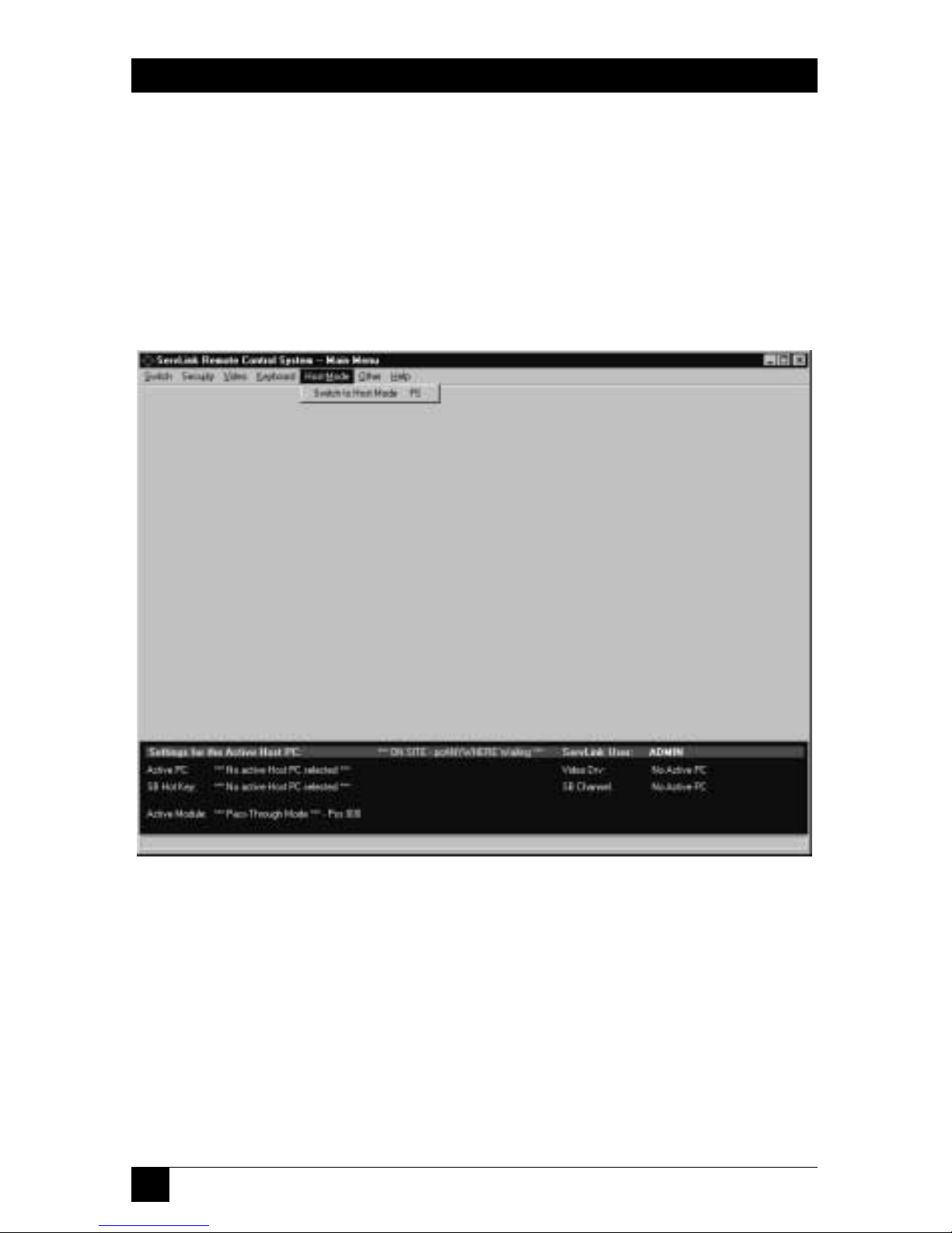
94
SERVLINK™
6.5 The Host Mode Menu: Switch to Host Mode
The fifth primary option available under the Main Menu is “Host Mode.” When
you pull down the Host Mode Menu, you’ll see a single selection, as shown in
Figure 6-32. When you select “Switch to Host Mode,” the ServLINK switches away
from the menu system and establishes a direct “Host Mode” connection with the
active Host PC: It displays that PC’s video and passes through keyboard and mouse
data to that PC. For more information on Host Mode, and on the Host Mode
Properties dialog box you can use to configure it, see Chapter 5.
Figure 6-32. The Host Mode menu.
Page 96
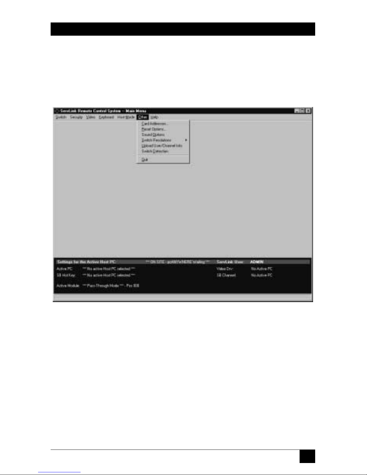
95
CHAPTER 6: The Menu System
6.6 The Other Menu
The sixth primary option available under the Main Menu is “Other.” When you
pull down the Other Menu, you’ll see seven selections, as shown in Figure 6-33.
These selections are discussed in the corresponding subsections on the following
pages.
Figure 6-33. The Other menu.
Page 97
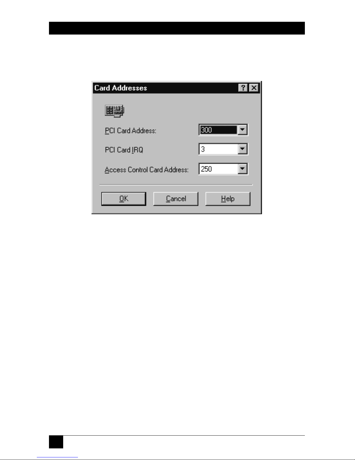
96
SERVLINK™
6.6.1 C
ARDADDRESSES
When you pull down the Other menu and select Card Addresses, the dialog box
shown in Figure 6-34 appears.
Figure 6-34. The Card Addresses dialog box.
We don’t recommend that you install extra cards or other hardware in the
ServLINK. But if you do, and the new hardware must use the address or the IRQ
assigned to the ServLINK’s PCI Card, or the address assigned to the ServLINK’s
Access Control Card, you can choose different settings for these Cards here. (This
is intended a last-resort fix for compatibility problems; if at all possible, leave the
PCI Card and Access Control Card in their default settings and change the new
hardware’s settings instead.)
• The default address for the PCI Card is 300 hex. Other available settings are
280, 2a0, 2c0, 340, and 360 hex.
• The default IRQ for the PCI Card is 3. Other available settings are 2, 4, 5, 7, 9,
10, and 11.
• The default address for the Access Control Card is 250 hex. Other available
settings are 260, 280, 300, 340, and 360 hex. (The Access Control Card’s IRQ is
not user-selectable.)
Page 98

97
CHAPTER 6: The Menu System
6.6.2 R
ESETOPTIONS(SERV
LINK P
OWER-CONTROLLED WITHPOWERMANAGEMENT
M
ODULEONLY
)
NOTE
For more details about Power Management Modules, refer to their own
manual.
When you pull down the Other menu and select Reset Options, the dialog box
shown in Figure 6-35 appears.
Figure 6-35. The Reset (Reboot) Options dialog box.
Use this option if you have a Power Management Module controlling power to the
ServLINK itself. (If you don’t, this box is irrelevant.) This Module should be
attached to the ServLINK’s modem through the ServLINK’s Access Control Card,
as described in Section 3.1.7.A. The one and only function of this Module is to
reboot the ServLINK when it receives a call with the characteristics specified here.
Two of these characteristics are mutually interdependent—either they both have
to be enabled or both disabled:
• Click the “Enable Reboot When Less Than” box to trigger a reboot on a call
with just a few rings. The default value is fewer than 3 rings; available values are
3 to 9 rings. This is the preferred reboot method.
• Click the “Enable Reboot When More Than” box to trigger a reboot on a call
that rings many times—the default value is more than 6 rings; available values
are 5 to 14 rings. The ServLINK’s modem is set to answer calls on the fourth
ring; if the few-rings reboot doesn’t work, and the modem fails to answer,
letting the call ring for the number of times specified here will trigger a reboot
anyway.
This brings up an interesting feature: Even though pcANYWHERE hangs up
after the tenth ring, this option can be set to more than 10 rings. This allows
Page 99

98
SERVLINK™
you to effectively disable the “reboot on many rings” option if you ever find
that badly mistaken or malicious people are dialing up the ServLINK, crashing
the modem, and then rebooting the ServLINK by calling back and letting it
ring.
If the Module is also attached to a secondary external modem as described in
step 6 in Section 3.1.7.A, you can call the secondary modem to trigger a reboot if
the primary line is dead, busy, or not responding for whatever reason:
• To set up this option, click the “Enable Reboot via external modem” box to
cue the Module to respond to calls on the secondary line, and set a password
for this feature in the field to the right. This password must be exactly ten
alphanumeric characters and cannot contain spaces. (You’ll also need to set
the secondary modem to auto-answer.)
To trigger this kind of reboot, dial the secondary modem from a PC running
terminal emulation; when the modem answers, type in “reset” and press
[Enter]. The Module will prompt you for the reboot password; if you enter it
correctly, the Module will hang up and cut power to the ServLINK for
20 seconds—or for whatever “Reboot Delay in Seconds” is set in the Control
Module Configuration box (see Section 6.1.3)—then power the ServLINK
back up.
At any time, you can click “Help” to get on-line help for this box. When you’re
finished, you can click “OK” to save your changes or “Cancel” to abort them.
Page 100

99
CHAPTER 6: The Menu System
6.6.3 S
OUNDOPTIONS
When you pull down the Other menu and select Sound Options, the dialog box
shown in Figure 6-36 appears.
Figure 6-36. The Sound Options dialog box.
If you install a SoundBlaster compatible sound card in the ServLINK, you can use
this option to customize the sound alerts the ServLINK gives you when (a) it sends
you a message or (b) when a remote user is accessing it. (If you enable the custom
sounds without such a sound card installed, the ServLINK will be totally silent.)
This can be especially useful in crowded server-room environments, where it can
be hard to tell which piece of equipment is making any given beeping noise.
Available sounds include “Speaker Beep” (the default), “Ding,” “Chime,” “Chord,”
“Gun Shot,” “Alert Voice,” “I’m Back,” and “Hello.” (These are .WAV files stored
on the ServLINK’s hard drive. While there’s no software-based way to add sounds
to this list, you can do a “Find File” on DING.WAV to locate the existing sound
files, back them up to some other folder, and give their filenames to other sounds
more appropriate for your application.)
To test what any of these selections sound like, pull the menu to that sound and
click “Test” to hear it. Volume control must be handled through the operating
system.
 Loading...