

Page 1

ACR1012A-T
®
®
ServSwitch Agility Dual with VNC
™
Extend quality DVI video, digital audio and USB
connections across your high speed network as
well as the internet to achieve ultimate system
flexibility.
This guide is an addendum to the ServSwitch Agility and Agility Dual user
guide and provides extra details that are specific to the ServSwitch Agility
Dual with VNC.
Customer
Support
Information
Order toll-free in the U.S.: Call 877-877-BBOX (outside U.S. call 724-746-5500)
FREE technical support 24 hours a day, 7 days a week: Call 724-746-5500 or fax 724-746-0746
Mailing address: Black Box Corporation, 1000 Park Drive, Lawrence, PA 15055-1018
Web site: www.blackbox.com • E-mail: info@blackbox.com
Page 2

ServSwitch Agility Dual with VNC
Trademarks Used in this Manual
Black Box and the Double Diamond logo are registered trademarks, and ServSwitch is a trademark, of BB Technologies, Inc.
Mac is a registered trademark of Apple Computer, Inc.
Linux is registered trademark of Linus Torvalds.
Windows is a registered trademark of Microsoft Corporation.
NetWare is a registered trademark of Novell, Inc.
Sun is a trademark of Sun Microsystems, Inc.
Unix is a registered trademark of UNIX System Laboratories, Inc.
BSD is a registered trademark of UUNet Technologies, Inc.
Any other trademarks mentioned in this manual are acknowledged to be the property of the trademark owners.
We‘re here to help! If you have any questions about your application
or our products, contact Black Box Tech Support at 724-746 -5500
or go to blackbox.com and click on “Talk to Black Box.”
You’ll be live with one of our technical experts in less than 60 seconds.
Page 2
724-746-5500 | blackbox.com
Page 3

FCC and IC RFI Statements
Federal Communications Commission and Industry Canada Radio Frequency Interference
Statements
This equipment generates, uses, and can radiate radio-frequency energy, and if not installed and used
properly, that is, in strict accordance with the manufacturer’s instructions, may cause inter ference to radio communication. It has
been tested and found to comply with the limits for a Class A computing device in accordance with the specifications in Subpart
B of Part 15 of FCC rules, which are designed to provide reasonable protection against such interference when the equipment is
operated in a commercial environment. Operation of this equipment in a residential area is likely to cause interference, in which
case the user at his own expense will be required to take whatever measures may be necessary to correct
the interference.
Changes or modifications not expressly approved by the party responsible for compliance could void the user’s authority to operate the equipment.
This digital apparatus does not exceed the Class A limits for radio noise emis sion from digital apparatus set out in the Radio
Interference Regulation of Industry Canada.
Le présent appareil numérique n’émet pas de bruits radioélectriques dépassant les limites applicables aux appareils numériques de
la classe A prescrites dans le Règlement sur le brouillage radioélectrique publié par Industrie Canada.
724-746-5500 | blackbox.com
Page 3
Page 4

ServSwitch Agility Dual with VNC
Instrucciones de Seguridad
(Normas Oficiales Mexicanas Electrical Safety Statement)
1. Todas las instrucciones de seguridad y operación deberán ser leídas antes de que el aparato eléctrico sea operado.
2. Las instrucciones de seguridad y operación deberán ser guardadas para referencia futura.
3. Todas las advertencias en el aparato eléctrico y en sus instrucciones de operación deben ser respetadas.
4. Todas las instrucciones de operación y uso deben ser seguidas.
5. El aparato eléctrico no deberá ser usado cerca del agua—por ejemplo, cerca de la tina de baño, lavabo, sótano mojado o cerca
de una alberca, etc..
6. El aparato eléctrico debe ser usado únicamente con carritos o pedestales que sean recomendados por el fabricante.
7. El aparato eléctrico debe ser montado a la pared o al techo sólo como sea recomendado por el fabricante.
8. Servicio—El usuario no debe intentar dar servicio al equipo eléctrico más allá a lo descrito en las instrucciones de operación.
Todo otro servicio deberá ser referido a personal de servicio cAgilityicado.
9. El aparato eléctrico debe ser situado de tal manera que su posición no interfiera su uso. La colocación del aparato eléctrico
sobre una cama, sofá, alfombra o superficie similar puede bloquea la ventilación, no se debe colocar en libreros o gabinetes
que impidan el flujo de aire por los orificios de ventilación.
10. El equipo eléctrico deber ser situado fuera del alcance de fuentes de calor como radiadores, registros de calor, estufas u otros
aparatos (incluyendo amplificadores) que producen calor.
11. El aparato eléctrico deberá ser connectado a una fuente de poder sólo del tipo descrito en el instructivo de operación, o como
se indique en el aparato.
12. Precaución debe ser tomada de tal manera que la tierra fisica y la polarización del equipo no sea eliminada.
13. Los cables de la fuente de poder deben ser guiados de tal manera que no sean pisados ni pellizcados por objetos colocados
sobre o contra ellos, poniendo particular atención a los contactos y receptáculos donde salen del aparato.
14. El equipo eléctrico debe ser limpiado únicamente de acuerdo a las recomendaciones del fabricante.
15. En caso de existir, una antena externa deberá ser localizada lejos de las lineas de energia.
16. El cable de corriente deberá ser desconectado del cuando el equipo no sea usado por un largo periodo de tiempo.
17. Cuidado debe ser tomado de tal manera que objectos liquidos no sean derramados sobre la cubierta u orificios de ventilación.
18. Servicio por personal cAgilityicado deberá ser provisto cuando:
A: El cable de poder o el contacto ha sido dañado; u
B: Objectos han caído o líquido ha sido derramado dentro del aparato; o
C: El aparato ha sido expuesto a la lluvia; o
D: El aparato parece no operar normalmente o muestra un cambio en su desempeño; o
E: El aparato ha sido tirado o su cubierta ha sido dañada.
Page 4
724-746-5500 | blackbox.com
Page 5

Table of Contents
Contents
1. Specifications .............................................................................................................................................................................. 6
2. Introduction ............................................................................................................................................................................... 7
3. Installation .................................................................................................................................................................................12
3.1 Mounting .........................................................................................................................................................................12
3.2 Connections ................................................................................................................................................................... 14
3.2.1 VNC network link ............................................................................................................................................... 14
3.2.2 Local video link(s) ................................................................................................................................................15
3.2.3 Local Audio Links ............................................................................................................................................... 16
3.2.4 Local USB Link .....................................................................................................................................................17
3.2.5 Local AUX Port ................................................................................................................................................... 18
3.2.6 Local Power In .................................................................................................................................................... 19
3.2.7 High speed links ................................................................................................................................................. 20
4. Configuration ........................................................................................................................................................................... 22
4.1 System and Teaming ports: Initial configuration .............................................................................................................. 23
4.2 The VNC port: Initial configuration ................................................................................................................................. 26
4.3 Initial configuration ......................................................................................................................................................... 28
4.4 Controls .......................................................................................................................................................................... 29
4.5 Mouse Control................................................................................................................................................................ 30
4.6 Advanced mouse configuration ...................................................................................................................................... 31
4.7 Info ................................................................................................................................................................................. 32
4.8 Power switching ............................................................................................................................................................. 32
4.9 Keyboard Control ........................................................................................................................................................... 33
4.10 Video settings ............................................................................................................................................................... 34
4.11 Editing the viewer window menu bar ............................................................................................................................ 35
4.12 Virtual Media ............................................................................................................................................................... 36
4.13 A rough guide to configuring TX and RX units .............................................................................................................. 40
4.14 Performing an upgrade ................................................................................................................................................. 43
4.15 Options switches ........................................................................................................................................................... 44
5. Operation ................................................................................................................................................................................. 45
5.1 Front Panel Indicators ...................................................................................................................................................... 45
5.2 Using the VNC viewer .................................................................................................................................................... 46
6. Further information .................................................................................................................................................................. 48
Appendix A. Configuration menus ....................................................................................................................................... 49
Appendix B. VNC viewer window options ............................................................................................................................ 66
Appendix C. The KVMADMIN utility .................................................................................................................................... 67
Appendix D. Java viewer options .......................................................................................................................................... 68
Appendix E. Hotkey sequences ............................................................................................................................................. 70
Appendix F. Known working video modes ........................................................................................................................... 72
Appendix G. Safety Information ........................................................................................................................................... 73
724-746-5500 | blackbox.com
Page 5
Page 6

ServSwitch Agility Dual with VNC
1. Specifications
ServSwitch Agility Dual with VNC
Casing (w x h x d): 198mm (7.92”) x 44mm (1.76”) x 145mm (5.7”)
Construction: 1U compact case, robust metal design
Weight: 1.11kg (2.44lbs)
Mount kits: Rack mount kits: Single (RMK2004) or dual units (RMK2004-2) per 1U slot.
VESA monitor / wall mount chassis kit: RMKVESA
Input Power: 100-240VAC 50/60Hz, 0.8A,
Output Power: 5VDC 20W
Operating Temperature: 0ºC to 40ºC (32ºF to 104ºF)
Approvals: CE, FCC
Page 6
724-746-5500 | blackbox.com
Page 7

Chapter 2: Overview
2. Introduction
Thank you for choosing the ServSwitch Agility Dual with VNC transmitter, part of the wider ServSwitch Agility family of products.
This advanced unit encodes high quality DVI video, audio and USB connections into Internet Protocol (IP) messages while offering
flexible signal switching capabilities and remote control facilities.
In concert with a ServSwitch Agility Dual receiver unit, the ServSwitch Agility Dual with VNC transmitter supports either two
single link DVI video streams or one dual link (very high resolution) DVI video stream. This is in addition to a microphone,
speakers and multiple USB peripherals. The distance between them is limited only by the size of your network.
ServSwitch Agility Dual with VNC provides a choice of link connections. Each unit supports both copper-based Gigabit
Ethernet cabling as well as Fibre Channel over Ethernet (FCoE). These can be used in parallel to provide up to 2 Gigabit connection speeds with the added benefit of link redundancy that can maintain operation in the event of a failed connection.
Additionally, the ServSwitch Agility Dual with VNC includes an in-built VNC server which allows it to stream low-bandwidth versions of its high-resolution output (via a dedicated Ethernet port on the front panel) so that it may be accessed remotely, via a VNC
viewer, through any standard network.
This concise guide acts as an addendum to the ServSwitch Agility and Agility Dual user guide to provide information about the extra features of your ServSwitch Agility Dual with VNC (ACR1012A-T).
2.1 Mixing ServSwitch Agility units
ServSwitch Agility Dual with VNC transmitters are complimentary to the standard ServSwitch Agility models which do not support dual DVI channels or fibre optic linking. It is possible to mix ServSwitch Agility, ServSwitch Agility Dual and ServSwitch
Agility Dual with VNC units on a network. However, whenever the two types are cross connected, the extra abilities of the
ServSwitch Agility Dual/ServSwitch Agility Dual with VNC units will be temporarily disabled.
2.2 ServSwitch Agility/Dual/VNC and ServSwitch iPath
Where multiple Agility units are used on a network, we have developed the ServSwitch iPath manager to allow comprehensive
and secure central control of all transmitters, receivers and users.
When using a ServSwitch iPath manager to configure Agility units, it is vital that all Agility units that you wish to locate and control are set to their factory default settings. Otherwise they will not be located by the iPath manager. If necessary, perform a fac-
tory reset on each Agility unit.
continued
724-746-5500 | blackbox.com
Page 7
Page 8

ServSwitch Agility Dual with VNC
2.3 One-to-One Configuration
The simplest configuration links one remote receiver unit to a single local transmitter unit, either by a direct link (up to 100m) or
over much greater distances via a Gigabit Ethernet network:
One-to-one configuration
2.4 One-to-Many Configuration
Using multicast techniques, an unlimited number of receivers* can receive video and audio data streams from a single local transmitter unit.
2.5 Low Bandwidth VNC Connection
Up to sixteen remote users can log in via standard networks to view the output from the ServSwitch Agility Dual with VNC:
Page 8
One-to-many configuration
Low bandwidth VNC connection
724-746-5500 | blackbox.com
Page 9
Chapter 2: Overview
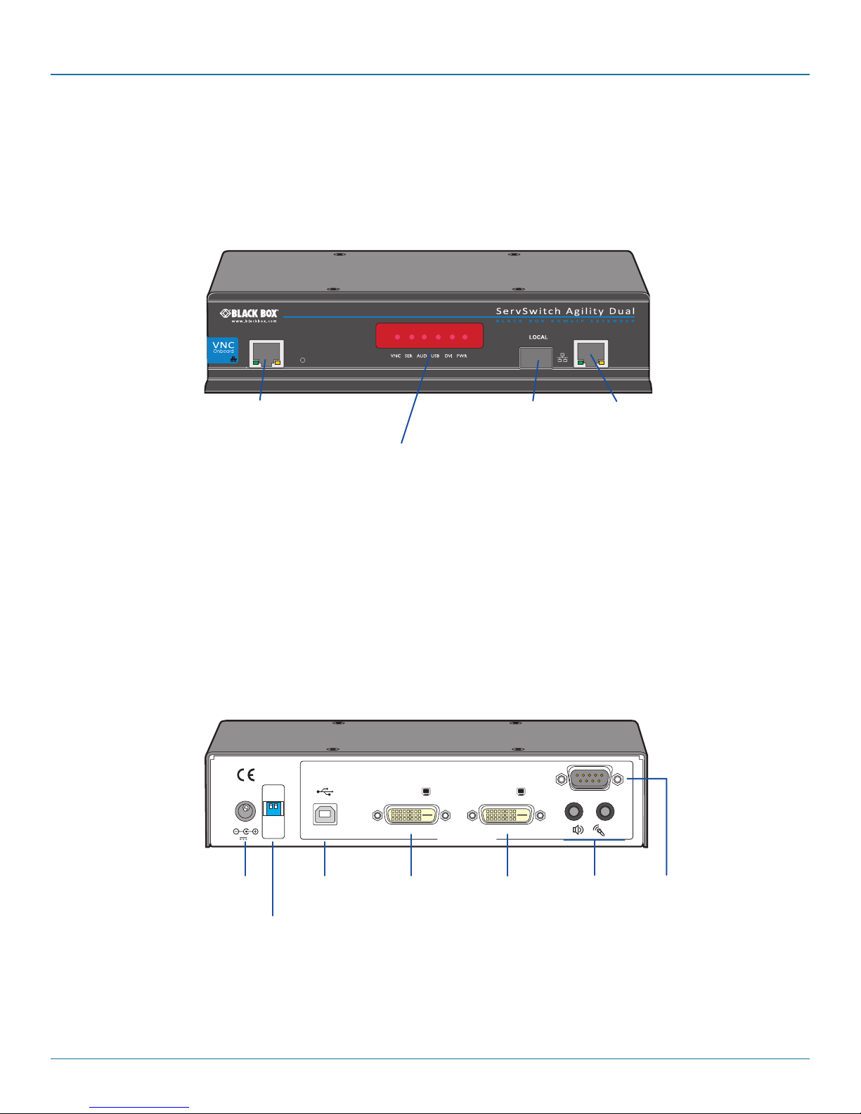
2.6 ServSwitch Agility Dual with VNC unit features
The ServSwitch Agility Dual with VNC unit is housed within a durable, metallic enclosure with most connectors situated at the
rear panel - the Ethernet and fiber are situated on the front panels.
2.6.1 ServSwitch Agility Dual with VNC local transmitter unit
The smart front faces feature the operation indicators as shown below:
VNC Port
Indicators
These six indicators clearly show the key aspects of operation:
• VNCOnwhenaVNCviewerisconnected.
• SER OnwhentheAUX(serial)portisenabledandactive.
• AUDOnwhenaudioisenabledandactive.
• USB OnwhenUSBisenabledandactive.
• DVI OnwhenDVIvideoisenabled.
• PWR Powerindicator.
The rear panel of the local transmitter unit contains most of the connectors:
INDOOR
OPTIONS
USE ONLY
5V 2.5A
ON
1 2
21
DVI-D-1
COMPUTER
DVI-D-2
Teaming
port
System
(Gigabit
Ethernet)
port
AUX
IN OUT
Power
input
Configuration
switches
USB
port
Primary
video
input
Secondary
video
input
724-746-5500 | blackbox.com
Audio
line
in/out
AUX
(serial)
port
Page 9
Page 10

ServSwitch Agility Dual with VNC
2.7 What‘s Included
Your package should include the following items. If anything is missing or damaged, contact Black Box at 724-746-5500
or info@blackbox.com.
2.7.1 ServSwitch Agility Dual with VNC Local Unit Package (ACR1012A-T)
• ServSwitchAgilityDualwithVNClocaltransmitterunit
• Poweradapterandpowercord
• Informationwallet
• Single link DVI-D to DVI-D video cable
• CombinedDVI-DandUSBcable(6feet)
• (2)audiocableswith3.5mmstereojacks(6.5feet)
• Upgrade(serialnullmodem)cable(6.5feet)
2.8 Additional Items You May Need
•Poweradapter(P/N:PS650)
•CombinedDVI-DandUSBcable(typeAtoB)(P/N:EHN900024U)
•SinglelinkDVI-DtoDVI-Dvideocable(P/N:EVNDVI02)
•USBcabletypeAtoB(6.5feet)(P/N:USB05)
•3.5mmAudiocable(6.5feet)(P/N:EJ110)
•Suitablefibermodules
•Upgrade(serialnullmodem)cable(6.5feet)(P/N:EYN257T-XXXX-FF)
•(2)19"rackmountbracketsand(4)screws(P/N:RMK2004orRMK2004-2)
•VESAmountingbracketand(4)screws(P/N:RMKVESA)
Page 10
724-746-5500 | blackbox.com
Page 11

Chapter 2: Overview
724-746-5500 | blackbox.com
Pa ge 11
Page 12
ServSwitch Agility Dual with VNC
AUX
LINE IN/
LINE OUT
MIC IN
1
2
INDOOR
USE ONLY
OPTIONS
LINE IN/
LINE O
DVI-D
1 2
USE R CO
5V
2.5A
MIC IN
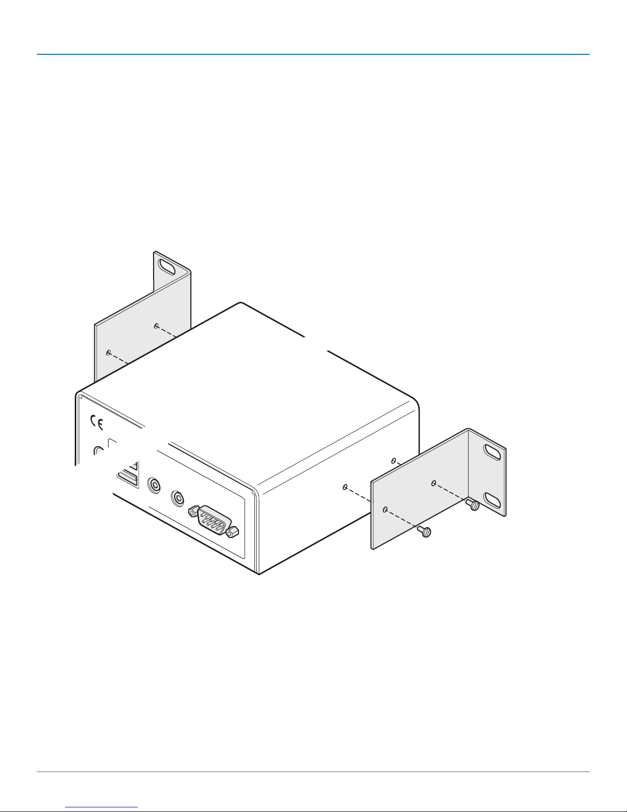
3. Installation
3.1 Mounting
There are three main mounting methods:
• Viathe(4)suppliedself-adhesiverubberfeet
• Viaoptionalrackmountbrackets
• ViatheoptionalVESAmountingbracket
3.1.1 Rack Brackets
The optional brackets (plus four screws), enable the unit to be secured within a standard rack slot:
NOTE: The ServSwitch Agility Dual with VNC unit and its power supply generate heat when in operation and will become warm
to the touch. Do not enclose them or place them in locations where air cannot circulate to cool the equipment. Do not operate
the equipment in ambient temperatures exceeding 104° F (40° C). Do not place the products in contact with equipment whose
surface temperature exceeds 104° F (40° C).
Page 12
724-746-5500 | blackbox.com
Page 13

Chapter 3: Installation
3.1.2 Using the VESA Mounting Bracket
The optional mounting bracket conforms to the VESA mounting standard and so can be used to mount a ServSwitch Agility unit
directly to the rear of most video display units. The bracket can also be fixed directly to a wall or other solid surface using appropriate screws or bolts.
1 Orientate the bracket against the rear of the video display so that its small folded-in tabs are lowermost:
ServSwitch
Agility unit
VESA mount-
ing bracket
NET SER AUD USB DVI PWR
Rear panel of video display
2 Attach the bracket to the video display using four screws of a size appropriate to the threaded holes within the video display
panel - do not overtighten.
3 Place the ServSwitch Agility unit into the bracket with its base facing towards the video display and the front panel of the
ServSwitch Agility unit facing upwards.
4 Secure the ServSwitch Agility unit to the bracket using the four supplied screws - do not overtighten.
724-746-5500 | blackbox.com
Page 13
Page 14

ServSwitch Agility Dual with VNC
3.2 Connections
Installation involves linking the ServSwitch Agility Dual with VNC local transmitter unit to various ports on the host computer,
while a ServSwitch Agility or Agility Dual remote receiver unit is attached to your peripherals.
3.2.1 VNC network link
The ServSwitch Agility Dual with VNC contains a VNC server that allows you to transmit a low-bandwidth version of the video
output across standard networks to authorized remote viewers.
The VNC link can either be made over the same network as the main System Ethernet port output or via a separate one. In either
case, a separate VNC network port is located on the left side of the Agility Dual with VNC front panel for the purpose.
1 Connect a CAT 5, 5e, 6, or 7 cable to the VNC socket on the left side of the front panel:
2 Connect the other end of the cable to an Ethernet switch.
Page 14
724-746-5500 | blackbox.com
Page 15
Chapter 3: Installation
COM PUTE R
DVI-D-1
DVI-D-2
COM PUTE R
DVI-D-1
DVI-D-2
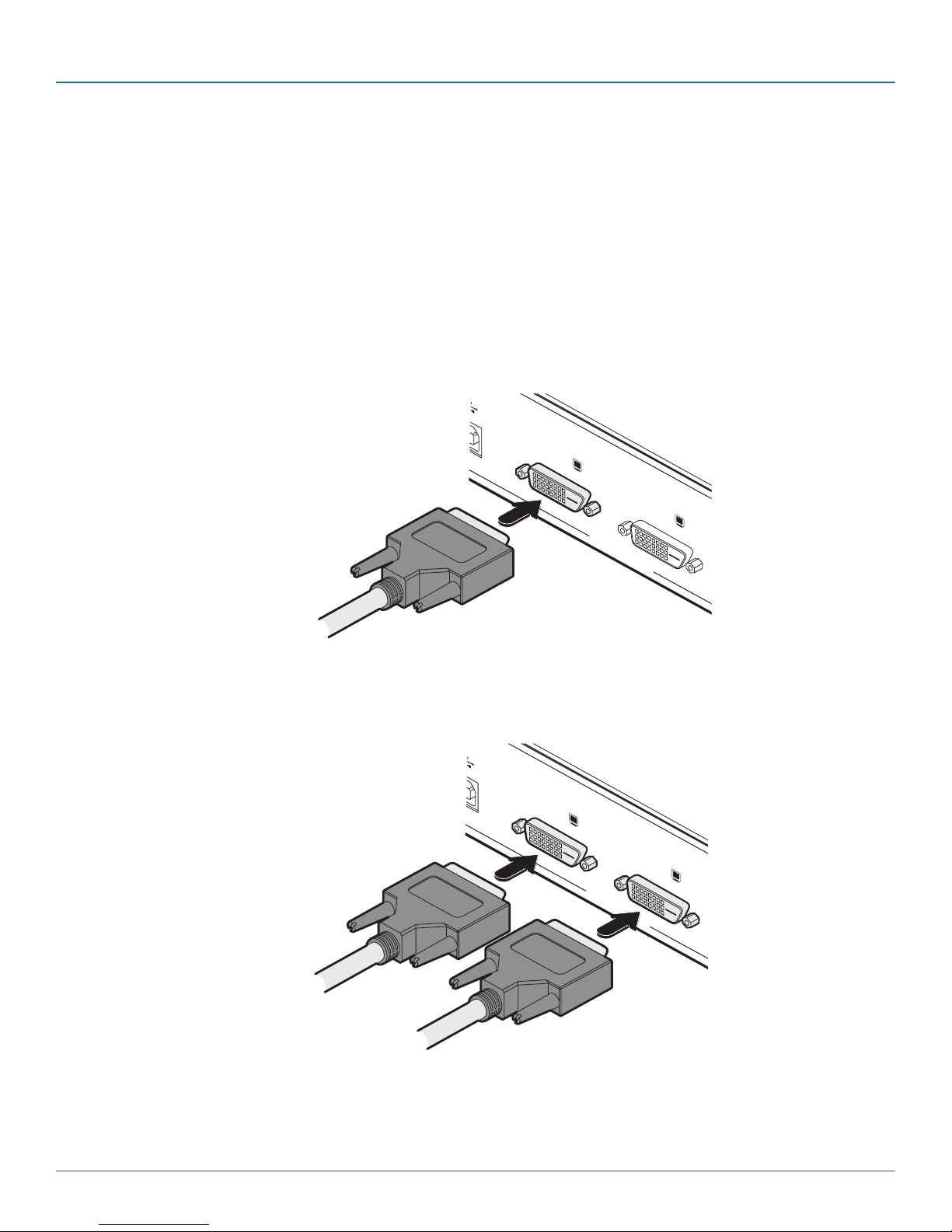
3.2.2 Local video link(s)
ServSwitch Agility Dual with VNC units can simultaneously support up to two Single Link high resolution video displays at pixel
clocks up to 165MHz; or can alternatively support a single Dual Link very high Resolution video display at pixel clocks up to
330MHz (equating to an example display mode of 2560 x 1600 at 60 Hz refresh). Use either a standard DVI-D cable (or
optionally a Dual Link DVI-D cable) to connect the primary video port of the computer system to the DVI-D-1 connector of
the ServSwitch Agility Dual with VNC. For dual link connections, a similar dual link cable must also be used at the remote unit.
Note: When using one very high resolution DVI-D dual link display, use a DVI-D Dual Link cable to connect the primary video port
of the computer system to the DVI-D-1 connector of the ServSwitch Agility Dual with VNC. A dual link cable must also be used at
the RX unit.
1 Wherever possible, ensure that power is disconnected from the ServSwitch Agility Dual with VNC and the host computer.
2 Connect a standard or dual DVI-D link cable to the DVI-D-1 socket on the Local unit rear panel:
Standard or dual link cable
from host computer
3 Connect the plug at the other end of the cable to the corresponding video output socket of the host computer.
4 If a secondary DVI-D link is required, repeat steps 2 and 3 for the DVI-D-2 socket:
From primary video output port
From secondary video output port
724-746-5500 | blackbox.com
Page 15
Page 16

ServSwitch Agility Dual with VNC
AUX
OUT
IN
3.2.3 Local Audio Links
All ServSwitch Agility units support two way stereo digital sound so that you can use a microphone as well as speakers.
1 Connect an audio link cable between the IN socket on the Local unit rear panel and the speaker output (line out) socket of
the host computer:
Speaker link from
host computer
Microphone link
to host computer
Connect the speaker and microphone cables to audio sockets.
2 [Where a microphone is to be used]: Connect a second audio link cable between the
panel and the Line In socket of the host computer.
OUT
socket on the Local unit rear
Page 16
724-746-5500 | blackbox.com
Page 17
Chapter 3: Installation
1 2
1
2
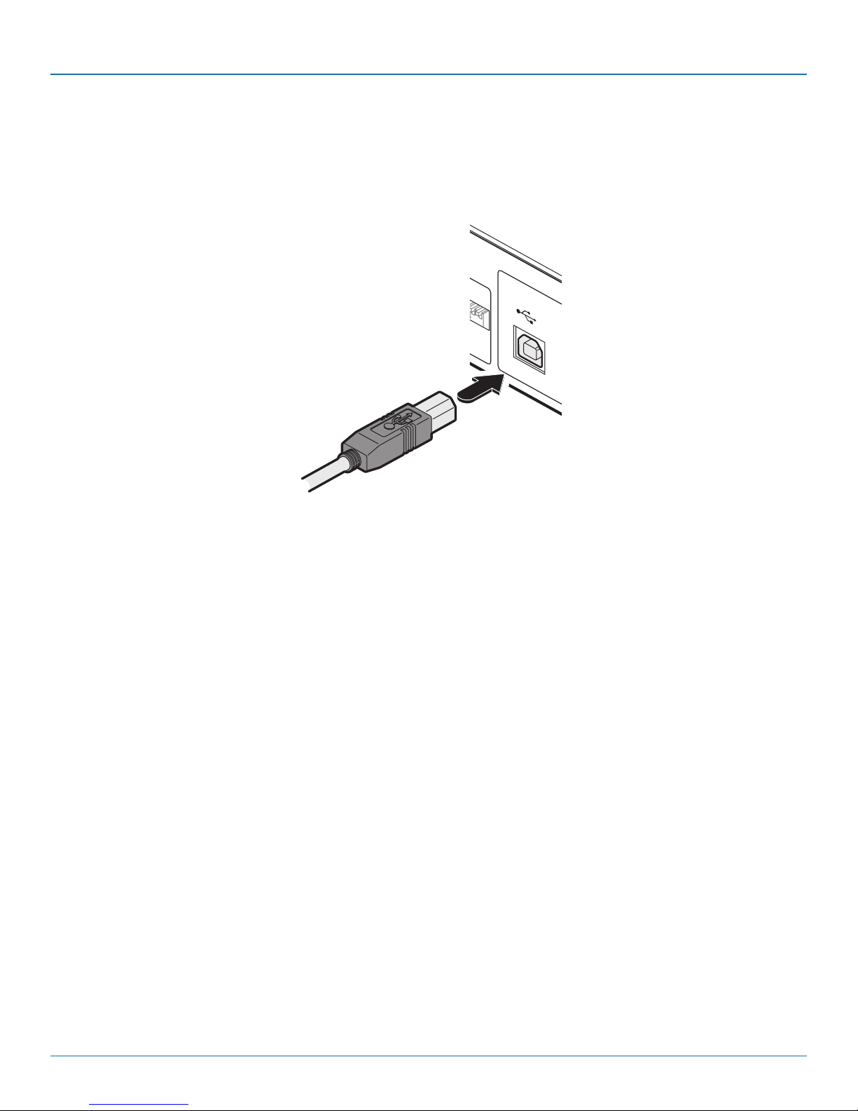
3.2.4 Local USB Link
All ServSwitch Agility units act as USB 2.0 hubs and so can provide four sockets at the Remote unit with only a single connection
at the Local unit.
1 Connect the type B connector on a USB cable to the USB port on the Local unit rear panel:
USB link from
host computer
Connect the USB link cable to Local unit socket.
2 Connect the type A connector of the cable to a vacant USB socket on the host computer.
724-746-5500 | blackbox.com
Page 17
Page 18

ServSwitch Agility Dual with VNC
AUX
3.2.5 Local AUX Port
The AUX port is an RS232 serial port that allows extension of RS232 signals up to a baud rate of 115200. The port has software
flow control, but no hardware flow control.
1 Ensure that power is removed from the ServSwitch Agility Dual with VNC unit.
2 Connect a suitable serial ‘null-modem’ cable between a vacant serial port on your computer and the AUX port on the right
hand side of the ServSwitch Agility Dual with VNC rear panel:
Serial (null-modem) link
from the host computer
Connecting the serial link cable to Local unit socket.
Page 18
724-746-5500 | blackbox.com
Page 19

Chapter 3: Installation
INDOOR
USE ONLY
OPT
1
5V
2.5A
1
3.2.6 Local Power In
The ServSwitch Agility Dual with VNC unit is supplied with an appropriate power supply - Note: Standard Agility units are supplied
with a slightly lower capacity supply (please see section 3.2.6.1 below).
1 Attach the output lead from the supplied power adapter to the 5V socket on the rear panel of the unit:
Note: Ensure that
Option switches 1
and 2 are both in
the ‘off’ (up) posi-
tion to enable nor-
mal operation of
the unit.
Power lead from
power supply
Connect the power supply to the rear panel power socket.
2 Connect the IEC connector of the supplied country-specific power lead to the socket of the power adapter.
3 Connect the power cord to a nearby power supply socket. When all other connections have been made, switch on the power
supply unit.
Note: Both the unit and its power supply generate heat when in operation and will become warm to the touch. Do not enclose
them or place them in locations where air cannot circulate to cool the equipment. Do not operate the equipment in ambient temperatures exceeding 40oC. Do not place the products in contact with equipment whose surface temperature exceeds 40oC.
3.2.6.1 Power supply identification
Due to the increased power requirements of the ServSwitch Agility Dual and Agility Dual with VNC units, these models are supplied with larger capacity (20W) power adapters. The standard 12.5W and higher power 20W adapters use identical housings, so
within installations where both types are used, you need to double check the underside labels to differentiate the two types:
12.5W m odel
(for Agility)
Model:SA06-xxxxx-V
Input: 100-240V
Output: 5V
2.5A (12.5W Max.) 4A (20W Max.)
SA0 6-xx xxx -V
2.5A (12.5W Max .)
100-2 40V
5V
Mod el:
Inp ut:
Out put :
20W m odel
(for Agility Dual)
Model:SA06-xxxxx-V
Input: 100-240V
Output: 5V
No damage will be caused if the 12.5W adapter (p/n
PS649-R3) and the 20W adapter (p/n PS650) are used
in place of each other on either of the Agility or Agility
Dual units. However, correct operation of Agility Dual
units can only be guaranteed if a 20W power adapter is
used. Always ensure that only the supplied (or
authorized replacement) 5-volt power supplies are used
to power the units.
How to differentiate the power supplies for the
ServSwitch Agility and Agility Dual
724-746-5500 | blackbox.com
Page 19
Page 20

ServSwitch Agility Dual with VNC
3.2.7 High speed links
ServSwitch Agility Dual (and Dual with VNC) units can be either connected directly to each other or via a high speed network.
The connections can be copper-based Gigabit Ethernet as well as Fibre Channel over Ethernet (FCoE). These can be used in parallel to provide up to 2 Gigabit connections speeds.
A single System port (Gigabit Ethernet) is provided as standard on the right side of the front panel. Additionally, the Teaming port,
located just to the left, allows you to insert either an optional Fibre Channel SFP module or Active Copper SFP module. The chosen module can then allow either a fibre optic or additional Gigabit Ethernet link to be used in parallel with the fixed System
(Gigabit Ethernet) port.
3.2.7.1 Using the Teaming port
1 Insert an appropriate optional SFP module into the aperture on the front panel:
Optional Fibre Channel or
Active Copper SFP module
2 Make your connection(s) between the chosen SFP module and either the other Agility Dual unit or a suitable network switch:
Transmit and
receive fibre links
Connect the transmit and receive
fibre optic links to the sockets on
the Fibre Channel SFP module.
Then close the latch over the link
connectors to lock them into place.
Page 20
Connect a CAT 5, 5e, 6, or 7 cable
to the socket on the Active Copper
or
SFP module.
724-746-5500 | blackbox.com
Page 21

Chapter 3: Installation
3.2.7.2 Using the System port
1 Connect a CAT 5, 5e, 6, or 7 cable to the System port socket on the front panel:
CAT 5, 5e, 6, or 7 link either
directly from the other Agility
Dual unit or from a Gigabit
Ethernet switch
2 Connect the other end of the cable either to the other Agility Dual unit or to a Gigabit Ethernet switch, as appropriate.
3 [For connections via a network] repeat steps 1 and 2 for the other Agility Dual unit.
3.2.7.3 Cable and fibre details
• Fordirectlinks over Ethernet cable, the length of cable should not exceed 100 metres (328 feet). Network cables used for connections may be category 5, 5e, 6 or 7 twisted-pair cable. Agility Dual with VNC units have an autosensing capability on their
network interfaces, so for direct point-to-point connections, no ‘crossover’ Ethernet cable is required.
• Fordirectlinksviafibre,varyingdistancescanbeachieveddependingonthemoduleandcabletypesused.
724-746-5500 | blackbox.com
Page 21
Page 22

ServSwitch Agility Dual with VNC
4. Configuration
The Agility Dual with VNC unit consists of two distinct sections (as detailed below) which each have their own separate configuration procedure:
The VNC port
Uses the standard Ethernet port on the left side of the
front panel and provides lower-bandwidth image video
feeds for use across standard networks and the wider
Internet.
Please see 4.2 The VNC port: Initial configuration
for details.
The System and Teaming ports
These use either the Gigabit Ethernet or (optional) Fibre Channel
over Ethernet (FCoE) module, on the right side of the front panel
and provide high resolution DVI-D image, audio and peripheral
feeds.
Please see the opposite page for details >>
Page 22
724-746-5500 | blackbox.com
Page 23

Chapter 4: Configuration
4.1 System and Teaming ports: Initial configuration
Agility Dual with VNC units are designed to be as flexible as possible and this principle extends also to their configuration.
4.1.1 Direct linking
Where Agility transmitters and receivers (all models) are directly linked to each other, very little configuration action is required,
provided that they have their factory default settings in place. If the standard settings have been changed in a previous installation, you merely need to perform a factory reset on each unit (see below).
4.1.2 Networked linking
Where Agility transmitters and receivers (all models) are connected via networked links, you can either configure them individually,
or configure them collectively using an Agility iPath server:
• Configuring networked Agility units individually - You need to specify the network addresses of the Agility units so that
they can locate each other. This is done by running the browser-based configuration utility on a computer system linked
to the same network as the Agility units.
• Configuring Agility units collectively - The Agility iPath server allows you to configure, control and coordinate any number
of Agility transmitters and receivers from a single application.
IMPORTANT: When using Agility iPath to configure Agility Dual units, it is vital that all units that you wish to locate
and control are set to their factory default settings. Otherwise they will not be located by the iPath server. If necessary, perform a factory reset on each Agility Dual unit (see below).
4.1.3 Manual factory reset
A factory reset returns an Agility transmitter or receiver unit to its default configuration. You can perform factory resets using the
browser-based configuration utility or by using this direct manual method.
4.1.3.1 To perform a manual factory reset
1 Remove power from the unit.
2 Use a narrow implement (e.g. a straightened-out paper clip) to press-and-
hold the recessed reset button on the front panel. With the reset button still
pressed, re-apply power to the unit and then release the reset button:
Use a straightened-out paper
clip to press the reset button
while powering on the unit
After roughly eight seconds, when the factory reset has completed, five of
the front panel indicators will flash for a period of three seconds to indicate
a successful reset operation.
724-746-5500 | blackbox.com
Page 23
Page 24

ServSwitch Agility Dual with VNC
S e r v S w i t c h Agi l i t y Dua l
™
B L A C K
B O X K V M o I P
E X T E N D E R
REMOTE
4.1.4 Browser-Based Configuration Utility
The browser-based configuration utility within all local transmitter and remote receiver units requires a network connection
between a ServSwitch Agility unit and a computer. This configuration utility allows you to perform all of the following functions:
• View/edittheIPnetworkaddressandnetmask,
• ConfigureseparateIPnetworkaddressesforvideo,audioandUSB,
• Configuremulticastsettings(onRemoteunits),
• Configurevideobandwidthsettings(onLocalunits),
• Viewthecurrentvideooutput(onLocalunits),
• Performafirmwareupgrade,
• Performafactoryreset.
4.1.4.1 Connecting a Computer System for Browser-Based Configuration
1 Connect a suitable network cable to the System (Gigabit Ethernet) port on the front panel:
Connect the ServSwitch Agility to a suitable network switch.
2 Connect the other end of the link cable to a network switch.
3 Similarly, link your computer to the same, or different, switch located on the same network. Note: A Gigabit connection is not
essential for configuration purposes.
4 If not already switched on, power up your computer and the ServSwitch Agility Dual with VNC unit. You are now ready to use
the browser-based configuration utility.
Page 24
724-746-5500 | blackbox.com
Page 25

Chapter 4: Configuration
4.1.4.2 Accessing the Browser-Based Configuration Utility
1 Temporarily connect the ServSwitch Agility Dual with VNC unit and a computer via a network, as discussed left.
2 Run a web browser on your computer and enter the IP address of the ServSwitch Agility Dual with VNC unit, e.g.
http://169.254.1.33
The default settings are as follows:
Agility Dual with VNC transmitter Agility Dual receiver
System port 169.254.1.33 169.254.1.32
Teaming port 169.254.1.43 169.254.1.42
Where the addresses of a unit is not known, perform a manual factory reset (see section 4.1.3) to restore the default
addresses.
The opening page of the ServSwitch Agility configuration utility should be displayed and you can now use on-screen help for
details of the functions that you wish to perform.
You can find further information about the configuration pages within the Appendix A later in this guide
724-746-5500 | blackbox.com
Page 25
Page 26

ServSwitch Agility Dual with VNC
4.2 The VNC port: Initial configuration
This section deals with the initial configuration of the VNC port of the Agility Dual with VNC unit. For details about the main
System and Teaming ports, please refer to 4.1 System and Teaming ports: Initial configuration.
The default IP address of the VNC port is 192.16 8 .1.42 ; it is possible to change this either through the VNC viewer or via the
Network configuration page.
4.2.1 Initial connection to the VNC port
Configuration of the VNC port section of the Agility Dual with VNC is carried via a network, using a VNC Viewer program running on a computer or mobile device. VNC Viewers are available for most computers, tablets and smartphones.
• IfyoualreadyhaveaVNCviewer,pleasefollowtheInitialconfigurationinstructionsgiveninsection4.3 Initial configuration.
If you do not already have a VNC viewer, there are three options:
• YoucandownloadaWindowsVNCViewerfromtheAgilityDualwithVNCitself.
• YoucandownloadthelatestVNCViewersformostoperatingsystemsviatheRealVNCwebsite,orfortabletsandsmart-
phones from the appropriate app store.
• Withoutdownloadinganything,youcanrunaJavaversionoftheVNCViewerinsideyourwebbrowser.
To download a Windows VNC Viewer from the Agility Dual with VNC unit
Note: The version of VNC supplied within the Agility Dual with VNC supports virtual media.
1 Connect the Agility Dual with VNC to an IP network where a suitable computer is available on the same subnet (please see the
Installation chapter for connection details).
2 On that computer, open an internet browser and enter the default local IP address used by the Agility Dual with VNC:
h t tp : / /192.168.1.42
The Agility Dual with VNC welcome screen should be displayed:
Page 26
724-746-5500 | blackbox.com
Page 27

Chapter 4: Configuration
3 Click the link ‘Download the Windows VNC Viewer from unit’.
4 Once the file is downloaded, run it and follow the on screen instructions to open a VNC connection to the Agility Dual with
VNC. (The VNC Viewer is a single executable file which does not require an ‘installation’ step. Simply put the file in a suitable
place (such as the Desktop) and run it from there.)
4.2.2 Note on viewers
The windows VNC viewer supplied by the unit is 4.4.3se4. On the Real VNC website you will find later viewers V5. The V5 viewers support a newer 256 bit encryption technique. However, Virtual media functionality is not supported in V5 viewer.
To download a VNC Viewer
To download a (free) VNC Viewer for a desktop or notebook computer, visit the download page of the RealVNC website.
To download a VNC Viewer app for a tablet or smartphone, visit the Apple or Android app store, or look at the RealVNC website
for further information.
To use the Java VNC Viewer
1 Connect the Agility Dual with VNC to an IP network where a suitable computer is available on the same subnet (please see the
Installation chapter for connection details).
2 On that computer, open an internet browser and enter the default IP address used by the Agility Dual with VNC:
http : / /192 .16 8 .1. 4 2
The Agility Dual with VNC welcome screen should be displayed (as shown above).
3 Click the link Connect using built-in Java VNC Viewer. The Java viewer will load and run inside the browser.
724-746-5500 | blackbox.com
Page 27
Page 28

ServSwitch Agility Dual with VNC
4.3 Initial configuration
To perform the initial configuration, you need to connect the Agility Dual with VNC to an IP network and use a computer located
on the same network to connect to it.
To perform the initial configuration
1 Connect the Agility Dual with VNC to an IP network (using the VNC port) where a suitable computer is available on the same
subnet (please see the section VNC network link for connection details).
2 Use a computer connected to the same subnet of the network.
On that computer, locate and select the VNC viewer icon
A connection details dialog will be displayed:
Options button
Provides a range of viewer and connection settings
Enter the Agility Dual with VNC address here and click OK
If required, select the encryption mode
3 In the ‘Server:’ entry, type the address: 192.168.1.42
4 Click the OK button. The viewer window may open straight away (if so continue at step 6) or the system may require user
authentication in which case an authentication dialog will be displayed:
5 Enter admin as the Username, leave the password entry blank and click the OK button. The viewer window should now
open:
Click the Configure button
Page 28
724-746-5500 | blackbox.com
Page 29

Chapter 4: Configuration
6 Click the Configure button to display the Configuration menu:
Use the various options (particularly the ‘Unit
Configuration’ and ‘Network Configuration’ options)
to arrange the Agility Dual with VNC to suit your
requirements.
See Appendix A - Configuration menus.
Note: To ensure that the Configuration menu is correctly displayed within the VNC viewer, the Agility Dual with VNC must be connected to the video output of its host computer.
4.4 Controls
When clicked, this button reveals a menu of options concerned with keyboard, video and mouse
operation.
Single Mouse Mode
This mode is for fast network connections where the cursor response is sufficient to provide instant
visual feedback on the remote screen. When enabled, the cursor is ‘captured’ within the viewer window until you use the ‘escape’ hot keys.
To quit from single mouse mode, press F8 and then P. Alternatively, enable and use the mouse button escape sequences - see Advanced unit configuration for details.
The single mouse mode does not require calibration.
Resync Mouse
This option has the same effect as the button on the menu bar and re-synchronises the local and remote mouse pointers.
Refresh Screen
This option refreshes the whole screen image to remove any artefacts from moved screen items. This is useful when using very
low refresh rates on slow speed communication links.
724-746-5500 | blackbox.com
Page 29
Page 30

ServSwitch Agility Dual with VNC
4.5 Mouse Control
This option displays a mouse control dialog and is useful when the remote cursor is failing to respond correctly to your mouse
movements, even after using the Resync mouse option.
The mouse control dialog allows you to control the remote mouse cursor using a selection of buttons that you click with your
local mouse.
Click to produce a single
mouse click for the left,
centre or right mouse
buttons
Click to move the remote
mouse cursor up, down,
left or right
Click to display
the Advanced
Mouse
Configuration
dialog. See next
page.
Click to produce a con-
tinuous mouse click and
hold for the left, centre
or right mouse buttons
Click to calibrate the
remote mouse
When ticked the unit will
attempt to switch to
Absolute Mouse mode
(recommended). If the
computer does not sup-
port this then it will dis-
play a warning and
return to relative mouse
mode.
Page 30
724-746-5500 | blackbox.com
Page 31

Chapter 4: Configuration
4.6 Advanced mouse configuration
This dialog allows the mouse acceleration to be configured according to the operating system in use and also permits manual fine
tuning for situations where problems are encountered with the Calibrate function.
For best results, choose the appropriate Change motion: entry to match the host in use.
The available Change Motion schemes are: Constant, XFree86, Windows Pre-XP, Windows XP, Windows XP SP2, OS/2, Solaris,
Solaris 9 and Mac OSX. Most of these offer the Speed setting as the only option, however, the Windows Pre-Xp and XFree86
options contain many other parameters.
When the Absolute Mode option is ticked in the main Mouse Control menu, this dialog allows you to adjust the Absolute Offset
scale:
724-746-5500 | blackbox.com
Page 31
Page 32

ServSwitch Agility Dual with VNC
4.7 Info
When selected, this option displays an information dialog showing the current logged on users, the current host, its video mode
and its mouse motion details.
4.8 Power switching
When configured (and where you have access rights) this option allows you to control the mains power input to the currently
selected host computer.
Note: This option is generally used to power cycle remote systems that have failed to respond. Before switching a system off,
ensure that all attempts have first been made to power it down through normal means.
An optional power switch is required to be connected to the AUX port of the Agility Dual with VNC unit in order to control the
mains power input into the associated computer. See also Power switching configuration.
To switch a system on or off
1 Use the Hosts button to select the required computer.
2 Click the Power button and then select the Switch on or Switch off option, as appropriate.
Page 32
724-746-5500 | blackbox.com
Page 33

Chapter 4: Configuration
4.9 Keyboard Control
This option displays a keyboard control dialog and is useful for sending keyboard combinations (to the host) that are needed regularly or that are trapped by the Agility Dual with VNC.
Click to send
Click to send
the code
Enter the
code here
When entering codes:
+ means press down the key that follows
the code
Click to send the contents of the
clipboard to the host
– means release the key that follows
+– means press down and release the key that follows
* means wait 250ms (note: if a number immediately follows the asterisk, then the delay will equal the number, in milliseconds)
It is automatically assumed that all keys specified will be released at the end, so there is need to specify -Ctrl or -Alt if these keys
are to be released together.
Examples:
‘Ctrl + Alt 12’ would be expressed as: +Ctrl+ Alt+1–1+2
+N means press the ‘N’ key
+Scroll means press the Scroll lock key
+Space means press the space key
Note: If using the Paste Clipboard feature, within the VNC viewer properties, ensure that in the Inputs section, the Share clipboard with server option is enabled.
724-746-5500 | blackbox.com
Page 33
Page 34

ServSwitch Agility Dual with VNC
4.10 Video settings
This option provides a range of options related to the video configuration.
Video source
Selects which video input to use. It is
possible to display both single head
screens (if connected) or select one over
the other. If you are viewing Dual-Link
video resolutions, only one head will be
available.
Use Remote DDC
Uses the DDC of the monitors connect-
ed to the Agility Reciever. If this option
is un-ticked you can select a DDC to use
that is reported by the Agility Dual with
VNC.
Hot Plug Detect
When ticked, allows you to choose one
of four hot plug detect periods when,
after a display is connected, the DDC
information is sought.
Ignore Dithering
Dithering is a technique used by some graphics cards
to improve perceived image quality by continuously
slightly varying the colour of each pixel. This gives the
illusion of more shades of colour than the display can
really reproduce, and smooths the appearance of
gradually shaded areas in images. Unfortunately, dith-
ering is an issue for KVM extenders because it makes
the image appear to be changing all the time even
when it is static. This means that a great deal of
unnecessary network data is sent to the VNC viewer,
reducing the video frame rate and making mouse
response appear slow.
The ‘Ignore Dithering’ option works by ignoring small
variations in the video from frame to frame. This
increases performance and reduces network traffic
when the host computer is an Apple Mac or another
computer that has dithered video output. It also
improves performance if the video source is noisy (e.g.
from a camera or a VGA-to-DVI converter). ‘Ignore
Dithering’ is disabled by default to give full colour
accuracy and the best possible frame rate from non-
dithered video sources.
Threshold
Adjusts the level of dithering noise that is
ignored. The ‘Auto’ button attempts to
choose a suitable value automatically, but
the level can also be adjusted manually using
the slider or arrow buttons. The best value is
of course a compromise between capturing
all the ‘real’ screen changes whilst ignoring
the (almost invisible) dithering noise. A good
way to choose the value is to watch the
Display Activity indicator for a static screen.
If the Threshold is too low, the Display
Activity will be a high percentage while
nothing is really changing. If the Threshold is
too high, the Display Activity will be very low
(or zero) but some real changes in the screen
may be missed.
Page 34
724-746-5500 | blackbox.com
Page 35

Chapter 4: Configuration
4.11 Editing the viewer window menu bar
If required, you can customise the menu bar of the viewer window to ensure that it contains only the necessary options.
The menu bar can be edited locally by each user or edited singly by the admin or alternatively, the admin can globally alter the
menu bar for all users.
To edit the menu bar locally
1 Login remotely via VNC viewer and display the viewer window.
2 Place the mouse pointer on the menu bar and
click the right mouse button. A popup will be
displayed:
3 Click on any option within the popup to add it to or remove it from the menu bar.
4 When all changes have been made, click anywhere else within the viewer window.
Changes made in this way will affect the individual user only.
To edit the menu bar via admin
1 Login remotely via VNC viewer as admin user and display the viewer window.
2 Click the Configure button in the top right corner of the viewer window.
3 Click the User Accounts button.
4 Against the entry for the required user, click
the Menu Bar Edit button. The following
dialog will be displayed:
Note: The local menu bar edit popup
shown above will only appear if the
Enable direct right click Menu editing
option is ticked within the Gui Edit
Configuration screen (for that user) as
shown right.
5 Select/deselect the items that you wish to appear on the menu bar. As you do so, the Menu bar appearance image will show
how the bar will look using your edited settings.
6 Optional: To globally apply your changes, tick the Apply to all users on Save option.
7 Click the Save button.
724-746-5500 | blackbox.com
Page 35
Page 36

ServSwitch Agility Dual with VNC
4.12 Virtual Media
The Virtual Media feature allows you to remotely make files available to a host computer that is linked to the Agility Dual with
VNC. Disk drives, single files or collections of files and folders up to 2GB in size can be mounted via the VNC link, and appear as a
read-only disk on the host. This can prove to be an invaluable tool when upgrading host computers from remote positions.
Note: The file transfer is in one direction only, from viewer to host.
Note: Virtual Media does not currently work with Apple Mac systems.
In order to use the Virtual Media feature, the VM link must be made between the Agility Dual with VNC and a USB port on the
host computer.
There are two main ways to use Virtual Media:
• Createaread-only‘virtualdiskdrive’onthehostfromoneormorefileschosenattheviewerend.Thisisusefulforcopying
one or more files from the computer running the VNC viewer to the host computer. See below.
• Exportadiskdrive(e.g.CD,DVDorUSBflashdrive)fromtheviewercomputersoitappearsasadiskonthehostattachedto
Agility Dual with VNC. A particular use for this is for booting or upgrading the remote host from a CD or other media that you
have at the viewer end.
4.12.1 Remotely transferring files to the host as a virtual disk drive
There are several methods of doing this. The easiest method depends on whether:
• Thefilesarealreadyontheclipboardoftheviewercomputer(followinganEdit -> Copy operation). See To remotely transfer
files from the clipboard >>
or
• Thefilesstillneedtobeselected.SeeTo select and remotely transfer files from the viewer computer >>
Page 36
724-746-5500 | blackbox.com
Page 37

Chapter 4: Configuration
To remotely transfer files from the clipboard
1 On the remote system, log into the Agility Dual with VNC using the VNC viewer.
2 If not already done, use Windows Explorer to locate and copy the required file(s), or folder(s) to the clipboard.
3 Within the VNC viewer window, click the Controls button and then select the Virtual Media option. A popup similar to the fol-
lowing will be displayed:
Click the Create VM Drive button to announce file availability to the host computer, whereupon a popup will confirm that the
new virtual media disk is built.
Note: Remember, at this point the selected files/folders have not yet been transferred to the host system, they are just visible
there.
4 On the host computer (via the VNC viewer) locate the new virtual drive (shown as a Removable Disk) and copy the files to the
required location on the host computer.
To select and remotely transfer files from the viewer computer
1 On the remote system, log into the Agility Dual with VNC using the VNC viewer.
2 Invoke the “Send Files” feature of the VNC viewer (called “File Transfer” in later versions), either by clicking the icon on the
viewer’s toolbar or selecting from the F8 menu.
3 The viewer will display a window allowing you to select files or a whole folder.
Highlight the required files or folders (up to a maximum of 2GB) that you wish to transfer to the host computer and click the
Open button. The new disk drive should appear on the host a few seconds later.
Note: The Use Entire Folder button provides a quick way to select a whole folder while you are viewing its contents.
Note: Remember, at this point the selected files/folders have not yet been transferred to the host system, they are just visible
there.
4 On the host computer (via the VNC viewer) locate the new virtual drive (shown as a Removable Disk) and copy the files to the
required location on the host computer.
Note: When using Virtual Media features, within the VNC viewer properties, ensure that in the Inputs section, the Share clipboard with server and the Enable file transfer options are enabled.
724-746-5500 | blackbox.com
Page 37
Page 38

ServSwitch Agility Dual with VNC
4.12.2 Remotely exporting a disk drive to the host
1 On the remote system, log into the Agility Dual with VNC using the VNC viewer.
Remote Drive(s)
This section lists any located storage devices
on the remote system that are 2GB or less,
and which could be copied en masse to the
host computer, if desired.
When the Create ISO Image option is
ticked this creates a bootable disk so that it’s
possible to boot the host computer from the
virtual media drive.
Remote Files or Folders
Click Browse to search for and select single
or multiple files/folders to be copied to the
host computer.
2 Press F8 and then V to display a Virtual Media dialog box:
3 You can select an entire drive or a disk image (e.g. .iso) file:
• Selectadiskdrive:Clickthecheckboxadjacenttothelisteddiskdrivethatyouwishtomakeavailabletothehostcomputer,
or
• AddaDiskImageFile:SelectthediskimagefileandclickOpen.
4 In the Virtual Media dialog box, click the OK button to announce the availability of the drive to the host computer. On the host
computer, the new drive will appear in the same way as any removable drive would on your computer.
Note: Remember, at this point the selected drive has not yet been transferred to the host system, it is just visible there.
5 On the host computer (either directly or via the VNC viewer) locate the new virtual drive (shown as a Removable Disk) and
copy the files to the required location on the host computer.
Note: The Remote File or Folder section of this Virtual Media dialog box provides yet another method of creating a virtual drive
from some files or folders, as described above.
Page 38
724-746-5500 | blackbox.com
Page 39

Chapter 4: Configuration
724-746-5500 | blackbox.com
Page 39
Page 40

ServSwitch Agility Dual with VNC
4.13 A rough guide to configuring TX and RX units
4.13.1 TX (transmitter) unit configuration
In an Agility dual system, the majority of configuration settings are dictated by the RX units. Therefore, the local TX unit setup
(using its browser-based configuration utility) is usually concerned only with three main factors: Its IP address details, the data
streams to enable/disable and video signal optimization. Other TX unit pages, such as USB Settings, System Messages, Firmware
Upgrades and Reboot are generally not used or altered during the majority of installations and are discussed elsewhere in this
guide. See Appendix A for explanations of all TX configuration page options.
Setting the TX address and output signal details
1 Display the TX unit System Configuration page.
2 Ensure that the IP address and netmask for the System port and the Teaming port (if used) are correct. The default settings of
169.254.1.33 and 169.254.1.43 for the two ports respectively are their zero config addresses - these are usually changed to
some other address suitable for your installation. Indeed, the zero config address for the System port MUST be changed before
the Teaming port can be used for network connections.
3 Check that the data streams (Enable Video, Enable Audio and Enable USB - plus Enable Serial, if used) are enabled as appropri-
ate. There are similar options within the RX unit configuration and it is important that the settings in both units are the same. If
an option is ticked in one unit but unticked in the other, then that data stream will remain disabled. If you make a change,
remember to click the Update Now button.
Optimizing the TX video signal
Note: Where the Agility dual system is linked via two Gigabit links with sufficient available bandwidth, there should be no need to
alter the default settings on this page.
1 Display the TX unit System Configuration page and then change to the Video Configuration page.
2 Make changes to the controls as necessary for each video port. There is no single combination of adjustments that will suit all
installations, but generally:
• Ifcolorqualityisimportant,thenleaveColourDepthat24bitsandadjustothercontrols,
• Ifmovingvideo images are being shown frequently, then leave Frame Skipping at a low percentage and instead reduce the
Peak Bandwidth Limiter and Colour Depth.
• Wherescreensarequitestatic,tryincreasingtheBackgroundRefreshintervaland/orincreasingtheFrameskippingpercent-
age setting.
Make changes one at a time, in small steps, and view typical video images so that you can attribute positive or negative results
to the appropriate control.
See Video Configuration for individual explanations of the controls.
3 Click Update Now to apply each setting change.
Page 40
724-746-5500 | blackbox.com
Page 41

Chapter 4: Configuration
4.13.2 RX (receiver) unit configuration
In an Agility dual system, it is the RX unit (receiver) that determines where and how data signals are sent (and received) by the TX
unit. Although numerous topologies (one-to-one, one-to-many, many-to-one, etc.) are made possible by the Agility system, they
are all dependent on two underlying modes of operation: either Unicast or Multicast transmission. Where multicast transmission is
not invoked for video and/or audio data, operation will be automatically served by unicast network transmission technologies.
The RX unit setup (using the System Configuration page of its browser-based configuration utility) is concerned with four main
factors: Its own IP address(es), the data streams to enable/disable, the IP address(es) of the TX unit and multicast transmission
details. Other pages, such as USB Settings, System Messages, Firmware Upgrades and Reboot are generally not used or altered
during the majority of installations. For further details about RX unit configuration pages, please see the Agility and Agility dual
guide.
Configuring the RX unit
1 Display the RX unit System Configuration page.
2 In the System Configuration section, ensure that the IP address and Netmask settings for the System and Teaming ports for this
RX unit are correct. The default settings of 169.254.1.32 and 169.254.1.42 for the two ports respectively are their zero config
addresses - these are usually changed to some other address suitable for your installation. Indeed, the zero config address for
the System port MUST be changed before the Teaming port can be used. Enter the new values and click the Update Now button. The System IP Address that is set here will be sent to the TX unit as the destination for transmitted data (when operating
in unicast mode). The Gateway entry is only necessary when the TX unit is located on a separate network to the RX unit.
3 Check that the data streams (Enable Video, Enable Audio and Enable USB - plus Enable Serial, if used) are enabled (ticked) or
disabled (unticked) as appropriate. There are similar options within the TX unit configuration; If one of these options is ticked in
one unit but unticked in the other, then that data stream will remain disabled. If you make a change, click the Update Now
button.
4 If necessary, alter the Audio Input Type to match your audio input. The line option is for a stereo line input, mic and mic boost
are for mono microphones, the latter benefiting from a +20dB gain boost.
5 In the Target Transmitter Unit Settings section, you need to enter the System port and Teaming port IP addresses for the TX
unit that will be supplying the video, audio, USB and serial data streams. This section allows you to determine which peripherals should use the second link. Most often all streams are supplied by the same TX unit, so common System and Teaming port
addresses can be applied to all streams. However, it is possible to receive them from different locations, in which case, click the
blue arrow to reveal the separate video, audio, USB and serial addresses. For all five peripherals, the System port of the targeted TX unit is always used to carry the respective data streams; your choices involve which of those five should also use the secondary Teaming port link to spread the load(s). For each peripheral, the first IP address is that of the targeted TX unit’s System
port. IP Address 2 corresponds to the Teaming port and is used only when the checkbox above is ticked. The default settings
for all entries are the standard IP addresses that are factory set within every TX unit (169.254.1.33 and 169.254.1.43). Change
these to the appropriate addresses on your transmitter(s) and click the Update Now button to save and activate them.
continued
724-746-5500 | blackbox.com
Page 41
Page 42

ServSwitch Agility Dual with VNC
6 For installations that will include more than one RX unit, for either video or audio or both, then you need to configure the
Multicast Settings section.
The two Video and the single Audio Multicast sub-sections are configured in exactly the same way:
• First,ticktheEnableMulticast Video / Enable Multicast Audio check box.
• Next,enterappropriateMulticastAddressesfortheSystemportVideo/Audiodatastream(s).ThesetofIPaddresses
between 224.0.0.0 and 239.255.255.255 are specifically reserved for multicast operations. Within a private enterprise network, you merely need to choose a location that is currently unused. However, if your link will pass through public networks,
then attention must be given to finding an address within these limits that is not already reserved for special use. The IANA
(Internet Assigned Numbers Authority) website: iana.org provides a list of publicly reserved addresses.
• Next,enterappropriateMulticastAddress2entriesfortheTeamingportVideo/Audiodatastream(s).
The video and audio multicast addresses must be different, as must the System and Teaming ports The addresses that you
enter will be used by the RX unit to ‘listen-in’ on the video and audio data streams output by the TX unit. The same IP
addresses need to be set on every RX unit that will similarly receive the video and audio data streams.
7 Click the Update Now button to save.
Repeat the IP addressing and multicast configuration steps for all RX units that will be part of the one-to-many installation.
For most installations, the successful implementation of these configuration steps will result in a correctly working system.
Page 42
724-746-5500 | blackbox.com
Page 43

Chapter 4: Configuration
4.14 Performing an upgrade
Agility Dual with VNC units are flash upgradeable using the method outlined here. However, for larger installations we recommend that you use the ServSwitch iPath manager to upgrade multiple Agility Dual units. When using the method below, the
Agility dual unit will be upgraded in sequence.
WARNING: During the upgrade process, ensure that power is not interrupted as this may leave the unit in an inoperable state.
If the upgrade process is interrupted and fails, it may be necessary to switch to the backup firmware image in order to regain
operation. See next page for details.
4.14.1 To upgrade a single unit via network link
1 Download the latest upgrade file from Black Box technical support.
Note: There are separate upgrade files for TX and RX units.
2 Temporarily connect the Agility Dual with VNC unit and a computer via a network (see browser-based configuration utili-
ty section for details).
3 Run a web browser on your computer and enter the IP address of the Agility Dual with VNC unit to be upgraded.
4 Click the Firmware Upgrade link. Within the Firmware Upgrade page, click the Choose File button. In the subsequent file dia-
log, locate the downloaded upgrade file - check that the file is correct for the unit being upgraded.
5 Click the Upgrade Now button. A progress bar will be displayed (however, if your screen is connected to the unit being
upgraded then video may be interrupted) and the indicators on the front panel will flash while the upgrade is in progress.
6 The indicators should stop flashing in less than one minute, after which the unit will automatically reboot itself. The upgrade
process is complete.
724-746-5500 | blackbox.com
Page 43
Page 44

ServSwitch Agility Dual with VNC
4.15 Options switches
A pair of Options switches are located on the rear panel of every Agility Dual with VNC unit.
4.15.1 Switch 1 - firmware image select
Each Agility Dual with VNC unit retains a backup firmware image which can be used in situations where the primary firmware
becomes corrupted (most often through failed upgrade operations). Using the backup firmware will allow you to regain operation
of the unit.
Option switch 1 OFF Normal operation using the main firmware
ON Operate using the backup firmware image
Option switch 2 is reserved and must remain in the OFF (up) position for normal operation.
Page 44
724-746-5500 | blackbox.com
Page 45

Chapter 5: Operation
5. Operation
In operation, many ServSwitch Agility installations require no intervention once configured. The local transmitter and remote
receiver units take care of all connection control behind the scenes so that you can continue to work unhindered.
5.1 Front Panel Indicators
The six front panel indicators on the ServSwitch Agility Dual with VNC unit provide a useful guide to operation.
These six indicators clearly show the key aspects of operation:
• VNCOn when a remote VNC connection is in progress.
• SEROnwhentheAUX(serial)portisenabledandactive.
• AUDOnwhenaudioisenabledandactive.
• USBOnwhenUSBisenabledandactive.
• DVIOnwheneitherorbothDVIvideochannelsareenabled.
• PWRPowerindicator.
724-746-5500 | blackbox.com
Page 45
Page 46

ServSwitch Agility Dual with VNC
5.2 Using the VNC viewer
1 On a network connected computer, locate and select the VNC viewer icon
A connection details dialog will be displayed:
Enter the Agility Dual with VNC address here and click OK
If required, select the encryption mode
Options button
Provides a range of viewer and connection settings
2 In the ‘Server:’ entry, type the network address that has been configured for the VNC port of the Agility Dual with VNC unit.
3 Click the OK button. The viewer window may open straight away or the system may require user authentication, in which case
an authentication dialog will be displayed:
4 Enter your Username and Password and click the OK button. The viewer window should now open Ü
Page 46
724-746-5500 | blackbox.com
Page 47

Chapter 5: Operation
Viewer options
(VNC viewer
only) Click the
VNC icon to
view the viewer
window options.
Re-sync mouse
Ensures that the
mouse pointer which
you move and the
mouse pointer on the
host system are cor-
rectly synchronised.
Ctrl Alt Del
Sends the
Ctrl Alt Del
sequence to
the current
host com-
puter.
Auto calibrate
This button will
calibrate the
mouse, but only
when relative
mouse mode is
selected.
Controls
Displays a menu
of options con-
cerning key-
board, video
and mouse
operation.
Hosts
Click to display a
list of computers.
Choose an entry
to connect to
that host com-
puter.
5.2.1 When using the viewer window
Power
Click to access
the power on /
off options for
the current
host computer.
Access mode
Allows you to
choose
between
Shared and
Private access
modes.
Dialog area
Indicates your username
and the host system that
you are currently viewing.
This area can also display
other messages.
Configure
This option is only
available to the
admin user and
provides access to
the main configura-
tion menus.
What is the best screen resolution to use?
The best resolution for your computer is one that is larger than the screen of the host computer that you are viewing. This will allow
you to see everything without scrolling around. Alternatively, the VNC viewer can be set to scale the image to fit your screen, but
remember that some pixel dithering effect will be seen when scaling is used.
How do I navigate around a larger screen?
If the screen that you are viewing has a larger resolution than your viewing window you will need to scroll around to see all items.
The viewer window allows you to ‘bump scroll’ (only in full screen mode). This means that when your mouse cursor bumps
against the edge of the screen, the screen image will scroll across automatically.
How do I escape from full screen mode?
Press the F8 button. This button is changeable but is most often set to F8.
How do I make the most of a slow connection?
The VNC viewer is slightly better suited to slower connections than the browser viewer because it offers more options. Click the
Options button of the VNC viewer when entering the Agility Dual with VNC address during log on.
Rate limit mouse events
When selected, this mode greatly reduces the mouse movement data that are sent to the host computer. When you move the
local mouse, the remote cursor will catch up roughly once per second.
724-746-5500 | blackbox.com
Page 47
Page 48

ServSwitch Agility Dual with VNC
6. Further information
This chapter contains a variety of information, including the following:
• AppendixA.Configurationmenus(viaVNC)-seeopposite
• Appendix B. VNC viewer window options
• Appendix C. The KVMADMIN utility
• Appendix D. Java viewer options
• Appendix E. Hotkey sequences
• Appendix F. Known working video modes
• Appendix G. Safety Information
Page 48
724-746-5500 | blackbox.com
Page 49

Appendices
Appendix A. Configuration menus (via VNC)
When viewing remotely via VNC, the unit has a main configuration menu through which you can access various sub menus to
configure particular items.
To view the main configuration menu
1 Using VNC viewer or a browser, log on as the ‘admin’ user.
2 Click the ‘Configure’ button in the top right corner. The main configuration menu will be displayed:
The various configuration pages are covered within this appendix:
• User accounts
• Gui edit configuration
• Unit configuration
• Advanced unit configuration
• Time & date configuration
• Network configuration
• Serial port configuration
• Host configuration
• Power switching configuration
• Logging and status
724-746-5500 | blackbox.com
Page 49
Page 50

ServSwitch Agility Dual with VNC
User accounts
Up to 16 users can be created by the admin user, each with their password. One of the 16 users can be the admin user. This user
has access to the units configuration menu. Ticking the ‘IsAdmin’ box creates the Admin user. The admin user can also determine
whether the users are allowed access to the power control menu in order to turn servers on and off.
User Name
All user names must consist of lower case characters or numbers only. No symbols or upper case characters are permissible. The
user name can be between 1 and 32 characters in length but cannot contain foreign characters.
Password
Each password can be between 1 and 16 characters in length. A suitable password is best constructed using a mixture of more
than 6 letters, numbers and punctuation characters.
Local
This column is greyed out as this feature is not available on Agility Dual with VNC.
Remote
When ticked, the selected user can gain access via an IP network link (such as a local intranet or the wider Internet, depending on
how the Agility Dual with VNC is connected) and/or Console Server access.
Power
When ticked, the selected user will be permitted to control the power input to host systems (requires optional power control
switch unit(s) to be fitted).
Menu Bar
Optionally click to customise the menu bar for each user. See next page.
Enable Password Hashing
This enables the storing of passwords in an encrypted format, which provides added security.
Page 50
724-746-5500 | blackbox.com
Page 51

Appendices
Gui edit configuration
If required, you can customise the menu bar of the viewer window to ensure that it contains only the necessary options.
The menu bar can be edited locally by each user or edited singly by the admin or alternatively, the admin can globally alter the
menu bar for all users.
To edit the menu bar locally
1 Login remotely via VNC viewer and display the viewer window.
2 Place the mouse pointer on the menu bar and click the right mouse button. A popup will be displayed:
3 Click on any option within the popup to add it to or remove it from the menu bar.
4 When all changes have been made, click anywhere else within the viewer window.
Changes made in this way will affect the individual user only.
724-746-5500 | blackbox.com
Page 51
Page 52

ServSwitch Agility Dual with VNC
Unit configuration
This page provides access to a selection of both basic and advanced settings for the Agility Dual with VNC. Many of the settings
displayed here are also accessible through the on-screen menu.
Hardware Version
Indicates the version of the electronic circuitry within the Agility Dual with VNC unit.
Firmware Version
Indicates the version of the internal software within the Agility Dual with VNC flash memory. This may be updated using the flash
upgrade procedure.
Host Keyboard Layout
Use the arrow buttons to match the keyboard layout expected by the host system.
Admin (Change) Password
Click this button to enter/edit the password that will be used to gain administrator access to the Agility Dual with VNC.
Unit Name
The name entered here will be displayed on the local menus and the remote VNC viewer/browser windows.
New Connections Private
Allows you to determine whether new local or VNC connections should be set up as private (when ticked) or as shared (when
unticked).
Menu Bar Toggle Hot Key
Determines the function key that can be used to display/hide the menu bar within the VNC screen.
Page 52
724-746-5500 | blackbox.com
Page 53

Appendices
Encryption
Four options are available: Always On, Prefer Off, Prefer On, or Maximum. The one to choose depends on the specific details of
your installation. The use of encryption imposes a slight performance overhead of roughly 10% but is highly secure against third
party intrusion. Maximum selects 256 bit encryption.
Number of simultaneous VNC Users
Allows you to restrict the number of concurrent VNC sessions. The maximum number is 16 and the default is 4.
VNC Viewer Hot Key Sequence
When using the VNC Viewer, you can use key press combinations to select host computers and also to display the host selection
menu. This option allows you to choose which keys should be used to form the hotkeys that will precede a switching command.
The default setting is CTRL + ALT, so as an example when you press the CTRL ALT and 2 keys, the viewer will change to the host
with “Hotkey Host Number” 2 - see Host configuration.
Advanced Unit Configuration
724-746-5500 | blackbox.com
Page 53
Page 54

ServSwitch Agility Dual with VNC
Advanced unit configuration
Click this button to display advanced options that do not normally require alteration.
Force VNC Protocol 3.3
IMPORTANT: Protocol 3.3 is a legacy version that does not offer any encryption. Hashed passwords are not supported with 3.3
Idle Timeout
Determines the period of inactivity on a global connection before the user is logged out. The idle timeout period can be set to any
time span, expressed in minutes.
Session Sleep Timeout
Determines the period of inactivity before the viewer screen will blank and a message is displayed. When no hosts are being
viewed either because of this time out or if no viewers are active then parts of the video circuitry are powered down reducing
power consumption by up to a third.
Protocol Timeout
Sets the time period by which responses should have been received to outgoing data packets. If the stated period is exceeded,
then a connection is considered lost and terminated.
Background Refresh Rate
Use the arrow keys to alter the background refresh rate used to correct any screen changes missed in normal operation. The
options are: Slow, Medium, Fast, Auto or Disabled. The Auto option automatically varies the refresh rate when multiple VNC sessions are active to provide a balance between the sessions.
Note: When a low connection speed is detected, the background refresh is automatically disabled, regardless of the settings of
this option.
Page 54
724-746-5500 | blackbox.com
Page 55

Appendices
Mouse Latency Allowance
This option is used during calibration to account for latency delays that may be caused as signals pass through a device.
During calibration, the Agility Dual with VNC waits for 40ms after each mouse movement before sampling the next. If a device
adds a significant delay to the flow of data, the calibration process can be lengthened or may fail entirely. The value entered here
is added to (or subtracted from) the default 40ms sampling time.
Note: You can enter negative values (down to -40) in order to speed up the calibration process when using fast KVM switches.
Use this option with caution as it can adversely affect the calibration process.
Mouse Rate
Defines the rate at which mouse movement data are transmitted to the system. The default option is 20ms, which equates to 50
mouse events per second. This is used to slow down the rate in exceptional circumstances but normally requires no adjustment.
Single Mouse Mode Mouse Switch
Select the mouse button combination to exit from single mouse mode (when active).
Use Quick Mouse Calibration
Invokes optimized calibration techniques that handle the majority of mouse types.
Behaviour for admin connections when limit reached
Determines what should occur when the limit on VNC users is reached. Options are: Replace oldest connection, Replace newest
connection and Don’t replace. Only non-administrator connections can be terminated in this way.
Enable Virtual Media
When ticked, allows the Virtual Media features to be used.
Reset Unit
Performs a complete cold boot of the Agility Dual with VNC unit.
724-746-5500 | blackbox.com
Page 55
Page 56

ServSwitch Agility Dual with VNC
Time & date configuration
This page allows you to configure all aspects relating to time and date within the unit.
Use NTP
When this option is selected, the Agility Dual with VNC will synchronise its internal clocks using information from the (Network
Time Protocol) server listed in the NTP Server IP address field.
NTP Server IP address
Optionally enter the IP address for a known Network Time Protocol server.
Set Time from NTP Server
Click to immediately use the time and date information from the listed NTP server.
Page 56
724-746-5500 | blackbox.com
Page 57

Appendices
Timezone specifier
Optionally enter a recognised timezone specifier related to the current position of the Agility Dual with VNC unit. When an NTP
server is used, the specifier will be used to provide the correct real time.
The timezone specifier takes the following form:
std offset dst [offset],start[/time],end[/time]
The std and offset specify the standard time zone, such as GMT and 0, or CET and -1, or EST and 5, respectively.
The dst string and [offset] specify the name and offset for the corresponding Daylight Saving Time zone; if the offset is omitted,
it defaults to one hour ahead of standard time.
The remainder of the specification describes when Daylight Saving Time is in effect. The start field is when Daylight Saving Time
goes into effect and the end field is when the change is made back to standard time. The most common format used for the
daylight saving time is: m.w.d
Where: m specifies the month and must be between 1 and 12. The day d must be between 0 (Sunday) and 6. The week w
must be between 1 and 5; week 1 is the first week in which day d occurs, and week 5 specifies the last d day in the month.
The time fields specify when, in the local time currently in effect, the change to the other time occurs. If omitted, the default is
02:00:00.
Typical examples are:
UK: GMT0BST,M3.5.0/1,M10.5.0/2
Central Europe: CET-1CEST,M3.5.0/2,M10.5.0/3
US Eastern: EST5EDT,M3.2.0/2,M11.1.0/2
US Pacific: PST5PDT,M3.2.0/2,M11.1.0/2
For further details
• Fordetailsoftimezonespecifierformats,pleasereferto:
http://www.gnu.org/software/libc/manual/html_node/TZ-Variable.html
• FordetailsoftheNetworkTimeProtocol(mainRFCnumber:1305;theSNTPsubsetusedasthebasisfortheAgilityDualwith
VNC: 4330)
http://www.ietf.org/rfc.html
724-746-5500 | blackbox.com
Page 57
Page 58

ServSwitch Agility Dual with VNC
Network configuration
This page allows you to configure the various aspects of the IP port.
MAC address
Media Access Control address – this is the unique and unchangeable code that was hard coded within your Agility Dual with VNC
unit when it was built. It consists of six 2-digit hexadecimal (base 16) numbers separated by colons. A section of the MAC address
identifies the manufacturer, while the remainder is effectively the unique electronic serial number of your particular unit.
IP Address
This is the identity of the Agility Dual with VNC within a network. The IP address can be thought of as the telephone number of
the Agility Dual with VNC. Unlike the MAC address, the IP address can be altered to suit the network to which it is connected. It
can either be entered manually or configured automatically using the DHCP option. When the DHCP option is enabled, this entry
is greyed out.
IP Network Mask
Also often called the subnet-mask, this value is used alongside the IP address to help define a smaller collection (or subnet) of
devices on a network. In this way a distinction is made between locally connected devices and ones that are reachable elsewhere,
such as on the wider Internet. This process helps to reduce overall traffic on the network and hence speed up connections in general.
Page 58
724-746-5500 | blackbox.com
Page 59

Appendices
IP Gateway
This is the address of the device that links the local network (to which the Agility Dual with VNC is connected) to another network such as the wider Internet. Usually the actual gateway is a network router and it will be used whenever a required address
lies outside the current network.
VNC Port
This is the logical link through which communications with a remote VNC viewer will be channelled. The default setting is 5900
which is a widely recognised port number for use by VNC software. However, in certain circumstances it may be advantageous to
alter this number - see ‘Security issues with ports’ for more details.
HTTP Port
This is the logical link through which communications with a remote web browser will be channelled. The default setting of 80 is
an established standard for web (HTTP – HyperText Transfer Protocol) traffic though this can be changed to suit your local network requirements.
IP Access Control
This section allows you to optionally specify ranges of addresses which will or won’t be granted access to the Agility Dual with
VNC. If this option is left unchanged, then the default entry of ‘+0.0.0.0/0.0.0.0’ ensures that access from all IP addresses will be
permitted. See Setting IP access control for details.
724-746-5500 | blackbox.com
Page 59
Page 60

ServSwitch Agility Dual with VNC
Setting IP access control
The golden rule with this feature is ‘Include before you exclude’ or to put it another way ‘Arrange allowed addresses in the list
before the denied addresses’.
This is because the positions of entries in the list are vitally important. Once a range of addresses is denied access, it is not possible
to make exceptions for particular addresses within that range. For instance, if the range of addresses from A to F are denied
access first, then the address C could not be granted access lower down the list. Address C needs to be placed in the list before
the denied range.
IMPORTANT: This feature should be configured with extreme caution as it is possible to deny access to everyone. If such an error
occurs, you will need to perform a reset to factory default settings in order to regain access.
In the list, access control addresses prefixed by ‘+’ are allow entries while those prefixed by ‘– ‘ are deny entries.
To define a new IP access control entry
1 Click the Add button to display a popup dialog:
Network/Address
Enter the network address that is to be allowed or denied access. If a range of addresses is being specified then specify any one of the
addresses within the range and use the Mask entry to indicate the size of the range.
Mask
Enter an IP network mask that indicates the range of
addresses that are to be allowed or denied access. For
instance, if only a single specified IP address were to be
required, the mask entry would be 255.255.255.255 in order
to specify a single location.
Access
Use the arrow buttons to select either
‘Allow’ or ‘Deny’ as appropriate.
2 Enter the base network address, the mask and select the appropriate access setting.
3 Click the OK button.
To reorder access control entries
IMPORTANT: When reordering, ensure that any specific allowed addresses are listed higher in the list than any denied addresses.
Take care not to invoke any deny access settings that would exclude valid users.
1 In the access control list, click on the entry to be moved.
2 Click the Up or Down buttons as appropriate.
To edit/remove access control entries
1 In the access control list, click on the appropriate entry.
2 Click either the Edit or Remove button as appropriate.
Page 60
724-746-5500 | blackbox.com
Page 61

Appendices
Serial port configuration
This page allows you to configure the baud rate of the Agility Dual with VNC serial port that is used to control power switch
devices. A full range of standard baud rates are available.
Baud Rate
Determines the communication speed of the OPTIONS port. The other communication settings are fixed as: No parity, 8 bit word,
1 stop bit.
724-746-5500 | blackbox.com
Page 61
Page 62

ServSwitch Agility Dual with VNC
Host configuration
This page provides the opportunity to configure various details for each of the host systems that may be connected to the Agility
Dual with VNC. Each entry can be configured with a name, the permitted users, the hot key combinations required to switch to it
and, if required, appropriate power control commands.
Sort
Allows you to reorder the list of hosts either alphabetically or by entry number.
Erase Host Configuration
Removes all hosts from the list.
Page 62
724-746-5500 | blackbox.com
Page 63

Appendices
To create a new host entry
1 Click one of the host entries to reveal a Host configuration dialog.
Name
Enter the name that will be displayed in the viewer window when you click the Host button.
Users
Select the users that will be permitted to connect to this host. Either enter * to allow all users or a list of users separated by
commas.
KVM Switch Macro
Declare the hot key sequence that will cause the KVM switch to link with the required host system.
Hotkey Host Number
Declare the numeric sequence that is pressed together with the VNC viewer hotkeys (usually Ctrl + Alt) to select this host
system, which is the same value as the KVM port number.
Power On
Enter the code required to make an attached power control unit apply power to the host. See Power switching configu-
ration for details.
Power Off
Enter the code required to make an attached power control unit remove power from the selected host.
Reboot
Enter the code required to make an attached power control unit remove power and then re-apply it a few seconds later.
2 Enter the required information in each field.
3 Click the OK button.
724-746-5500 | blackbox.com
Page 63
Page 64

ServSwitch Agility Dual with VNC
Power switching configuration
Power switch configuration comprises two main steps:
• ConfiguretheOPTIONS serial port to the same speed as used by the power switch box(es), using the Serial port configura-
tion menu.
• ConfigurepowerONandOFFstringsforeachrelevanthostcomputer.
For each power port there needs to be a valid ‘Power ON string’ and similarly an appropriate ‘Power OFF string’. In each case, the
strings are a short sequence of characters that combine a port address and a power on or off value.
If a particular computer has more than one power input (and thus requires an equivalent number of power ports to control
them), collections of strings can be combined to switch all of the required ports together as a group.
To configure the power sequences for each host computer
1 Using VNC viewer or a browser, log on as the ‘admin’ user.
2 Click the ‘Configure’ button in the top right corner.
3 Click the ‘Host configuration’ option.
4 Click a host entry to display a Host configuration dialog:
5 If necessary, configure other parameters (Name, Users, Hot Keys - MORE).
6 Enter the Power control sequences in the Power On, Power Off and Reboot fields
7 Click OK to close the dialog and then click the Save button in the main Host Configuration window to store the details.
Page 64
724-746-5500 | blackbox.com
Page 65

Logging and status
This screen provides various details about the user activity on the Agility Dual with VNC unit.
Appendices
Date and time the
event occurred
Type of event, user name and access method or remote IP address
Click to clear
all log entries
Click to
refresh the list
Optionally enter an IP
address to which the
status log should be
sent
Click to return
to the main
menu
To copy and paste the log
You can copy the information listed within the log and paste it into another application.
1 While viewing the log screen, press Ctrl and C, to copy the data into the clipboard.
2 In a text application (i.e. Word, WordPad, Notepad) press Ctrl and V, or right mouse click and ‘Paste’.
Syslog Server IP Address
Logging information can optionally be sent, as it occurs, to a separate system using the standard Syslog protocol. Enter the IP
address of a suitable system in the field provided.
For further details
• FordetailsoftheSyslogprotocol(RFCnumber:3164)
http://www.ietf.org/rfc.html
724-746-5500 | blackbox.com
Page 65
Page 66

ServSwitch Agility Dual with VNC
Appendix B. VNC viewer window options
Click the VNC icon in the top left corner of the viewer window (or press F8) to display the window options:
Standard window control items
Full screen
Expands the VNC viewer window to fill the whole screen with no visible window edges
or toolbar. Press F8 to re-display this menu.
Single mouse mode (P)
Used for fast network connections where a second, “predictor” cursor is not required.
Ctrl, Alt, Send F8, Send Ctrl-Alt-Del
Sends the selected keypress(es) to the Agility Dual with VNC and host computer. This is
necessary because certain keys and key combinations are trapped by the VNC viewer.
Refresh Screen
Requests data from the server for a complete redraw of the screen image, not just the
items that change.
Virtual Media...
Allows files to be transferred from the remote computer to the host.
Send Files to Server...
Allows files to be transferred from the remote computer to the host.
New connection...
Displays the connection dialog so that you can log on to a different Agility Dual with
VNC or VNC server location.
Options...
Displays the full range of connection options.
Connection info...
Displays various connection and display details.
About...
Displays information about your VNC viewer.
Page 66
724-746-5500 | blackbox.com
Page 67

Appendices
Appendix C. The KVMADMIN utility
Particularly useful for complex Agility Dual with VNC configurations and the control of remote installations, KVMADMIN is a powerful administration tool.
KVMADMIN is based upon the established VNC viewer and uses the same security system. Rather than a graphical interface such
as the standard viewer, KVMADMIN uses command line control to provide the following administration facilities:
• DiscoverandadjusttheAgilityDualwithVNCconfiguration,includinghostsystems,
• SaveandrestoretheAgilityDualwithVNCconfiguration,
• Setusernamesandpasswords,
• Downloadtheeventlog,
The use of KVMADMIN is strictly limited to the ‘admin’ user and for security purposes it is not possible to retrieve user names or
passwords from the Agility Dual with VNC.
To use KVMADMIN you require the IP address and admin password of the Agility Dual with VNC unit. The command line is as
follows:
kvmadmin <command> <ip address> [<parameters>]
where <command> is one of the following:
• -setconfig<config-file>
• -getconfig<config-file>
• -setusers<csv-file>
• -getlog<log-file>
• -gethosts<csv-file>
• -sethosts<csv-file>
• -setmodes<csv-file>
For instance, the command line:
kvmadmin -getconfig kvm1.cfg 192.168.2.1
... downloads the current configuration from the Agility Dual with VNC unit at the given address and stores it in the local file
kvm1.cfg.
Whereas the command line:
kvmadmin -setusers users.csv 192.168.2.1
... configures the usernames and passwords for the same unit from the local file users.csv.
For more information about KVMADMIN, please refer to the user notes supplied with the utility.
724-746-5500 | blackbox.com
Page 67
Page 68

ServSwitch Agility Dual with VNC
Appendix D. Java viewer options
When you are connecting to the Agility Dual with VNC using the Java viewer, a number of options are available.
Click here to
access the options
There are four options pages:
Encoding and colour level
Auto select
When ticked, this option will examine the speed of your connection to the Agility Dual with
VNC and apply the most suitable encoding method. This option is suggested for the majority of
installations.
Preferred encoding
There are three manually selectable encoding methods which are accessible when the Auto
select option is unticked.
• ZRLE – This is a highly compressed method that is best suited to slow modem connections.
• Hextile – This method offers better performance than the ZRLE when used over a high
speed network because there is no need for the Agility Dual with VNC to spend time highly compressing the data.
• Raw – This is a primitive, uncompressed method that is mainly used for technical support issues. You are recommended not to
use this method.
Colour level
The colour level is fixed at Medium (256 colours) for almost all browsers.
Inputs
View only (ignore mouse & keyboard)
When ticked, the viewer will not send keyboard or mouse information to the Agility Dual with
VNC or host computer.
Accept clipboard from server
This feature is restricted to software server versions of VNC and has no effect on Agility Dual
with VNC installations.
Send clipboard to server
This feature is restricted to software server versions of VNC and has no effect on Agility Dual with VNC installations.
Page 68
724-746-5500 | blackbox.com
Page 69

Security
512 bits (low security)
Selects the lowest level of encoding for communications between the browser and the Agility
Dual with VNC.
1024 bits (medium security)
Selects the middle level of encoding for communications between the browser and the Agility
Dual with VNC.
2048 bits (high security)
Selects the highest level of encoding for communications between the browser and the Agility Dual with VNC.
Misc
Shared (don’t disconnect other viewers)
This feature is restricted to software server versions of VNC and has no effect on Agility Dual
with VNC installations.
Appendices
Render cursor locally
This feature is restricted to software server versions of VNC and has no effect on Agility Dual
with VNC installations.
Fast CopyRect
This option should remain enabled.
724-746-5500 | blackbox.com
Page 69
Page 70

ServSwitch Agility Dual with VNC
Appendix E. Hotkey sequences
Agility Dual with VNC allows you to enter commands suitable for any KVM switch in order to choose from up to 128 host systems.
These switching commands can take the form of hotkey sequences that emulate standard keypress combinations.
Hotkey sequences
Almost any combination of keypresses can be emulated using the following notations:
+ means press down the key that follows;
– means release the key that follows
+– means press and then release the key that follows
means add a delay. The standard delay period is 250ms, however, if a number immediately follows the asterisk,
*
this will define an alternate delay period (in milliseconds)
Notes
• The entries are not case sensitive.
• AllcharacterscanbeenteredusingtheirASCIIcodes,from32to126(i.e.A,B,C,…1,2,3etc.)withtheexceptionofthespecial
characters above.
• Itisnotnecessarytospecifyallkeystobereleasedattheendbecausetheyareallreleasedautomaticallyafterthelastcode.
• AnumberofKVMswitchesfromalternativemanufacturersusehotkeysequencesthatbeginwithapress/releaseofeitherthe
Scroll Lock or Ctrl keys. These often require a delay between the initial key press and the channel number to allow the switch
to respond. A 500ms delay is usually sufficient.
Examples
To send the command Ctrl + Alt 4 you should use the following: +Ctrl+Alt+4.
To send the command Ctrl + Alt 12 you should use the following: +Ctrl+ ALT+ –1+2
(the ‘+–1’ entry causes the 1 key to be pressed and released before the 2 key is pressed).
To send the command Scroll lock 1 + Enter (with a 500ms delay) you should use the following: +–Scr*500+1+Ent
Main control keys (see ‘Using abbreviations’)
Backspace | Tab | Return | Enter | Ctrl | Alt | Win | Shift | LShift | RShift
LCtrl | RCtrl | LAlt | AltGr | RAlt | LWin | RWin | Menu | Escape | Space
CapsLock | NumLock | PrintScreen | Scrolllock
Math operand keys (see ‘Using abbreviations’)
Add (Plus) | Subtract (Minus) | Multiply
Central control keys (see ‘Using abbreviations’)
Insert | Delete | Home | End | PageUp | PageDown
Up | Down | Left | Right | Print | Pause
Page 70
724-746-5500 | blackbox.com
Page 71

Appendices
Keypad keys (see ‘Using abbreviations’)
KP_Ins ert | KP_Del ete | KP_Hom e | KP_En d | KP_PageUp
KP_PageDown | KP_Up | KP_Dow n | KP_Lef t | KP_Right | KP_Enter
KP_Add | KP_Su btract | KP_Div ide | KP_Multiply
KP_0 to KP_9
Function keys
F1 | F2 | F3 | F4 | F5 | F6 | F7 | F8 | F9 | F10 | F11 | F12
Creating macro sequences
Hot key macro sequences can be up to 256 characters long. All keys are assumed to be released at the end of a line, however,
you can also determine that a key is pressed and released within a sequence. Any of the following three examples will send a
command that emulates and a press and release of the Scroll Lock key:
+SCROLL-SCROLL
+-SCROLL
+SCROLL-
Example:
+-SCROLL+-SCROLL+1+ENTER
Press and release scroll twice, press 1 then enter then release all keys (equivalent definition is +SCROLL-SCROLL+SCROLLSCROLL+1+ENTER-1-ENTER)
Using abbreviations
To reduce the length of the key definitions, any unique abbreviation for a key can be used. For example: “scroll”, “scr” and even
“sc” all provide an identifiable match for “ScrollLock” whereas “en” could not be used because it might mean “Enter” or “End”
(“ent” would be suitable for “Enter”).
Note: Hotkey sequences and abbreviations are not case sensitive.
724-746-5500 | blackbox.com
Page 71
Page 72

ServSwitch Agility Dual with VNC
Appendix F. Known working video modes
640x480 @ 60Hz
720x480 @ 60Hz
768x576 @ 60Hz
800x480 @ 60Hz
1024x600 @ 60Hz
1024x768 @ 60Hz
1152x768 @ 60Hz
1152x864 @ 60Hz
1280x720 @ 60Hz
128 0x768 @ 60Hz
1280x800 @ 60Hz
1280x854 @ 60Hz
1280x960 @ 60Hz
1280x1024 @ 60Hz
1366x768 @ 60Hz
1400x1050 @ 60Hz
1440x900 @ 60Hz
1440x960 @ 60Hz
1600x900 @ 60Hz
1600x1200 @ 60Hz
1680x1050 @ 60Hz
1920x1080 @ 60Hz
1920x1200 @ 60Hz
2048x768 @ 60Hz
2048x1080 @ 60Hz
2048x1152 @ 60Hz
2048x1536 @ 60Hz
2048x2048 @ 60Hz
2560x1440 @ 60Hz
2560x1600 @ 60Hz
2560x2048 @ 50Hz
Page 72
724-746-5500 | blackbox.com
Page 73

Appendices
Appendix G. Safety Information
• Foruseindry,oilfreeindoorenvironmentsonly.
• Theunitsandtheirpowersuppliesgenerateheatwheninoperationandwillbecomewarmtothetouch.Donotenclosethem
or place them locations where air cannot circulate to cool the equipment. Do not operate the equipment in ambient temperatures exceeding 40 degrees Centigrade. Do not place the products in contact with equipment whose surface temperature
exceeds 40 degrees Centigrade.
• Warning-livepartscontainedwithinpoweradapter.
• Nouserserviceablepartswithinpoweradapter-donotdismantle.
• Plug the power adapter into a socket outlet close to the module that it is powering.
• Replace the power adapter with a manufacturer approved type only.
• Do not use the power adapter if the power adapter case becomes damaged, cracked or broken or if you suspect that it is not
operating properly.
• If you use a power extension cord with a unit, make sure the total ampere rating of the devices plugged into the extension
cord does not exceed the cord’s ampere rating. Also, make sure that the total ampere rating of all the devices plugged into the
wall outlet does not exceed the wall outlet’s ampere rating.
• Do not attempt to service the units yourself.
724-746-5500 | blackbox.com
Page 73
Page 74

Black Box Tech Support: FREE! Live. 24/7.
Tech support the
way it should be.
Great tech support is just 60 seconds away at 724-746-5500 or blackbox.com.
®
®
About Black Box
Black Box Network Services is your source for an extensive range of networking and infrastructure products. You’ll find everything
from cabinets and racks and power and surge protection products to media converters and Ethernet switches all supported by
free, live 24/7 Tech support available in 60 seconds or less.
© Copyright 2014. Black Box Corporation. All rights reserved.
ACR1012A-T, rev. 1
724-746-5500 | blackbox.com
 Loading...