

Page 1
Model ACL201A
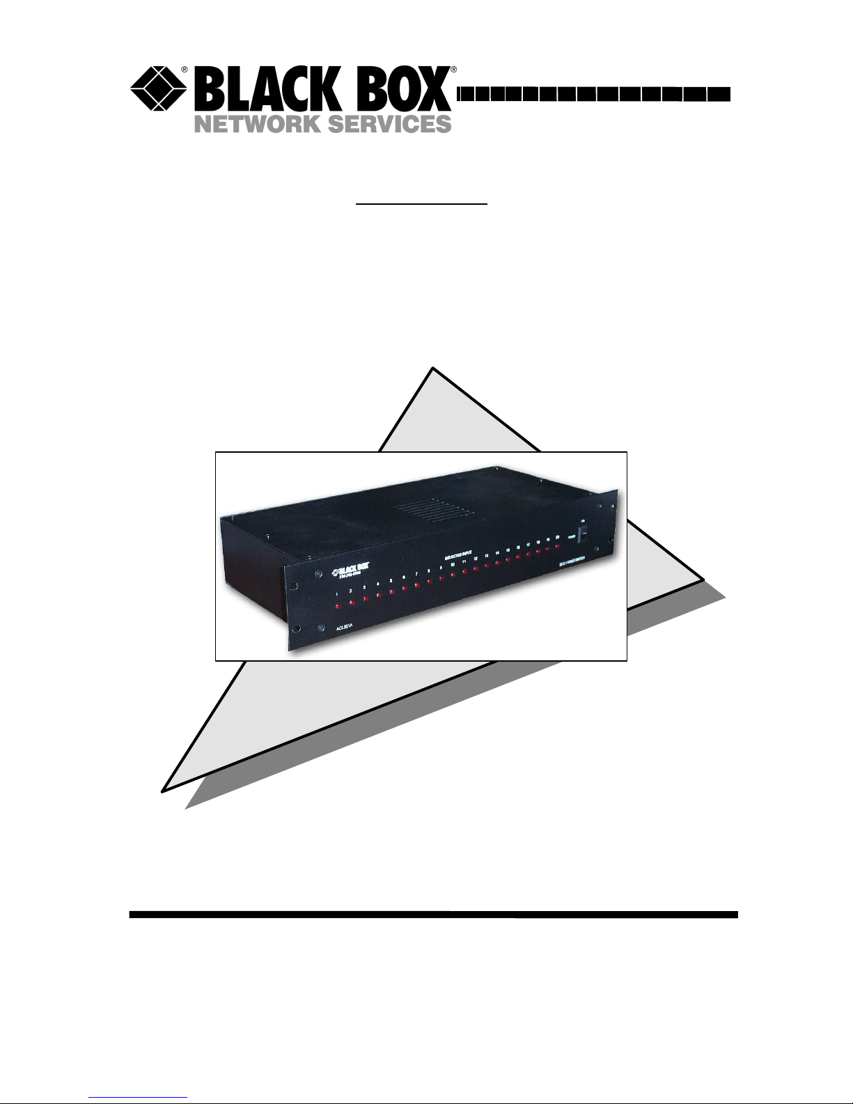
20 in x 1 out PC (VGA) Video Switch
March 2004
CUSTOMER
SUPPORT
INFORMATION
Order toll-free in the U.S. 24 hours, 7 A.M. Monday to midnight Friday:
877-877-BBOX
FREE technical support, 24 hours a day, 7 days a week:
Call 724-746-5500 or fax 724-746-0746
Mail order: Black Box Corporation, 1000 Park Drive, Lawrence, PA 15055
Web site: www.blackbox.com • E-mail: info@blackbox.com
Page 2

Page 3

ss
20 in x 1 out PC (VGA) Video Switch
1
TRADEMARKS USED IN THIS MANUAL
Black Box, and (logo) are trademarks of Black Box Corporation.
IBM is a registered trademark of International Business Machines
Corporation. Any other trademarks mentioned in this manual are
acknowledged to be the property of the trademark owners.
FEDERAL COMMUNICATIONS COMMISSION
RADIO FREQUENCY INTERFERENCE STATEMENT
This equipment generates, uses, and can radiate radio frequency energy
and if not installed and used properly, that is, in strict accordance with
the manufacturer’s instructions, may cause interference to radio
communication. It has been designed and found to comply with the
limits for a Class A computing device in accordance with the
specifications in Subpart B of Part 15 of FCC rules, which are intended
to provide reasonable protection against such interference when the
equipment is operated in a commercial environment. Operation of this
equipment in a residential area is likely to cause interference, in which
case the user at his or her own expense will be required to take
whatever measures may be necessary to correct the interference.
Changes or modifications not expressly approved by the party
responsible for compliance could void the user’s authority to operate
the equipment.
This digital apparatus does not exceed the Class A limits for radio
noise emission from digital apparatus set out in the Radio Interference
Regulation of the Canadian Department of Communications.
EUROPEAN UNION DECLARATION OF CONFORMITY
This product complies with the requirements of the European EMC
directive 89/336/EEC
Page 4

Model ACL201A
2
Contents
1. Introduction ............................................................................page 3
1.1 Model ACL201A ..................................................................page 3
1.2 Features ..................................................................................page 4
2. Installation................................................................................page 4
3. Configuration and Operation .................................................page 5
4. Troubleshooting .......................................................................page 6
Contacting Black Box................................................................page 6
Shipping & Packaging................................................................page 6
5. Specifications............................................................................page 7
Page 5

ss
20 in x 1 out PC (VGA) Video Switch
3
1. Introduction
1.1 Model ACL201A
The Model ACL201A is a 20 in x 1 out video switch that allows a
monitor to display any of the 20 inputs.
The inputs can be RGBHV (e.g. VGA from a PC), RGBS, or RGsB
with resolutions to 1600x1200 pixels, all inputs are terminated and
buffered using 250 MHz DC-coupled video amplifiers for a sharp and
perfect reproduction at each output.
The ACL201A's output can drive cables in excess of 300 feet. Each
channel provides a user selectable compensation for long cable runs.
The compensation should be applied to those inputs where the total
length of the cable from that particular input to the monitor exceeds 150
feet.
An RS232 "Serial Port" is provided on the unit to control the selection
for the output. A Serial Keypad is supplied with each unit. The
ACL201A has a built-in universal power supply and requires standard
110/220 v AC, 50 or 60 Hz for operation. A power cord is furnished
with the unit.
The ACL201A employs HDD15 female connectors for all video inputs
and outputs (with standard VGA pinout). All cable connections are
located on the rear of the unit. The front panel provides the on/off
power switch and individual indication of the channels selected for each
output. The brightness of the Channel LED's on the front panel is an
indication of the "compensation" setting for that channel.
The ACL201A’s output can also be blanked.
Page 6

Model ACL201A
4
1.2 Features
• 20 inputs to 1 output
• Can drive long cables
• Output can also be blanked
• Amplifies the signal for clean and crisp transmission
• Handles resolutions up to 1600x1200 at any refresh rate
• Rugged, Reliable, Compact & Rack-mountable size
• Universal Power Supply
• Perfect for Remote Monitoring, Video Staging, Conference
Rooms, Classrooms and more
2. Installation
1. Make sure the unit is powered off.
2. Connect your video sources to the input connectors (labeled
IN 1 through 20)
3. Connect the Monitor or projector to the connector (labeled
OUTPUT).
4. Connect the keypad to the RS232 port on the device (labeled
KEYPAD).
5. Connect and power up the optional external numeric display to
connector labeled DISPLAY.
6. Plug the power cord to the unit and turn the unit on using the
front panel switch.
Shown
with
Optional
Remote Channel Display
Page 7

ss
20 in x 1 out PC (VGA) Video Switch
5
3. Configuration &
Operation
Upon power-up, the device performs a self-test and selects the previously
displayed input (also recalls the compensation level that was used.
Select input channels by pressing the following key sequence on the keypad:
Single or Double digit input channel number, followed by ENTER
For example, to select input #12 punch: 12e
In entering the keys, you have 5 seconds to hit enter or the operation is
automatically cancelled. So if you stop for more than 5 seconds, the keypad
automatically resets itself. Also, if you press a key that is unexpected (such as
Esc or *) or if the channel is out of range, it will be ignored and the keypad
resets once again.
Special Characters:
Ø To blank the output signal altogether, enter zero for input.
i.e.: 0e
Ø To apply compensation to any input press: +
This clears up the display when long cables are used. The LED on the front
panel will be brightened.
Ø To turn compensation off for a particular input press: -
This causes the signal gain to go down, and the LED on the front panel will be
dimmed.
Note
The unit stores the compensation status of the outputs after power off
Page 8

Model ACL201A
6
4. Troubleshooting
If you have a stable image but it looks somewhat blurry (object or
character edges are not sharp), try to adjust the compensation first.
Press + or – on the Keypad to apply to remove the compensation.
Contacting Black Box
If you determine that your Switch is malfunctioning, do not attempt to
repair the unit. Contact Black Box Tech. Support at 724-746-5500.
Before you do, make a record of the history of the problem. We will be
able to provide more efficient and accurate assistance if you have a
complete description.
Shipping and Packaging
If you need to transport or ship your extender:
• Package it carefully. We recommend that you use the original
container.
• Before you ship the units back to Black Box Corporation for
repair or return, contact us to get a Return Authorization (RA)
number.
Page 9

ss
20 in x 1 out PC (VGA) Video Switch
7
5. Specifications
Video Types VGA through UXGA, RGB , YPbPr , or YCbCr
Resolution Up to 1600 x 1200 at up to 85 Hz
Bandwidth DC to 250 MHz
Max. Distance Up to 300 ft. (90 m)
Connectors HD15 female for video in and out
Interfaces Standard Analog VGA; RS-232
Max. Altitude 10,000 ft. (3048 m)
Temperature Operating: 32 to 122°F (0 to 50°C);
Storage: –40 to +185°F (–40 to +85°C)
Humidity Up to 95% non-condensing
Enclosure Steel
MTBF 65,000 hours (calculated estimate)
Power 110 to 240 vAC, 50 to 60 Hz
Size 15.5 " wide x 3.19" high x 10" deep
Weight 15 lbs. (shipping)
Page 10

Model ACL201A
8
Page 11

Page 12

© Copyright 2004. Black Box Corporation..
All rights reserved.
1000 Park Drive Lawrence, PA 15055-1018 724-746-5500 Fax 724-746-0746
 Loading...