

Page 1

CUSTOMER
SUPPORT
INFORMATION
Call our Technical Support Specialists to discuss your application.
For 24-hour technical support: Call (412) 746-5500 or Fax: 1-800-321-0746
To order: Call (412) 746-5500 8:00 A.M. to 8:00 P.M. EST
Mail order: Black Box Corporation, P.O. Box 12800, Pittsburgh, PA 15241
®
JUNE 1996
IC495A-R2
SCSI Fiber Optic Extender
Black Box Corporation
The Source for Connectivity
®
LINK ACTIVE
BUS ACTIVE
LINK ERROR
SCSI FIBER OPTIC EXTENDER
POWER
Page 2
2
SCSI Fiber Optic Extender
FEDERAL COMMUNICATIONS COMMISSION
RADIO FREQUENCY INTERFERENCE STATEMENT
This equipment generates, uses, and can radiate radio frequency energy
and if not installed and used properly, that is, in strict accordance with the
manufacturer’s instructions, may cause interference to radio
communication. It has been tested and found to comply with the limits for a
Class A computing device in accordance with the specifications in Subpart B
of Part 15 of FCC Rules, which are designed to provide reasonable
protection against such interference when the equipment is operated in a
commercial environment. Operation of this equipment in a residential area
is likely to cause interference, in which case the user at his own expense will
be required to take whatever measures may be required to correct the
interference.
Changes or modifications not expressly approved by the party responsible
for compliance could void the user’s authority to operate the equipment.
“This digital apparatus does not exceed the Class A limits for radio noise
emission from digital apparatus set out in the Radio Interference
Regulation of the Canadian Department of Communications.”
“Le présent appareil numérique n’émet pas de bruits radioélectriques
dépassant les limites applicables aux appareils numériques de la classe A
prescrites dans le Règlement sur le brouillage radioélectrique édicté par le
ministère des Communications du Canada.”
TRADEMARKS
All applied-for and registered trademarks are the property of their
respective owners.
ST®is a registered trademark of American Telephone and Telegraph
Company.
Page 3
3
CHAPTER 1: Specifications
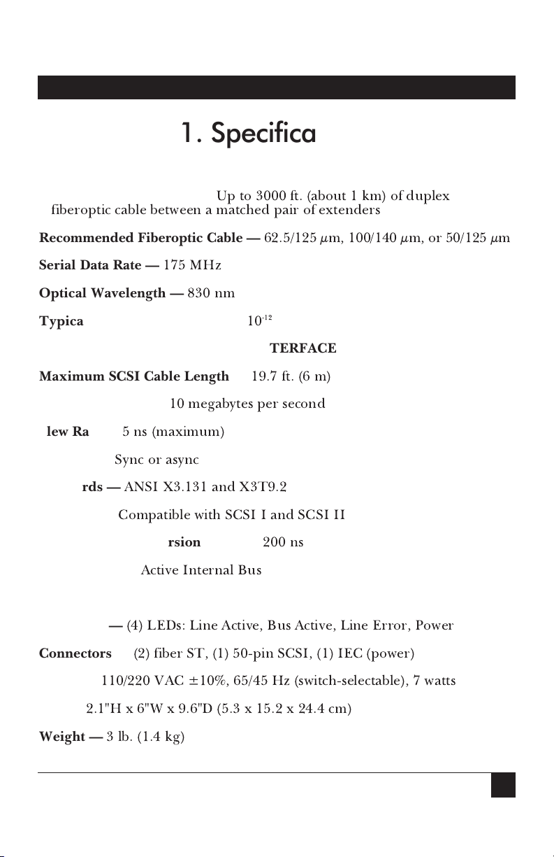
FIBEROPTIC INTERFACE
Maximum Cable Length —
Up to 3000 ft. (about 1 km) of duplex
fiberoptic cable between a matched pair of extenders
Recommended Fiberoptic Cable —
62.5/125 µm, 100/140 µm, or 50/125 µm
Serial Data Rate —
175 MHz
Optical Wavelength —
830 nm
Typical Bit Error Rate (BER) —
10
-12
SCSI INTERFACE
Maximum SCSI Cable Length —
19.7 ft. (6 m)
Maximum Speed —
10 megabytes per second
Slew Rate —
5 ns (maximum)
Protocol —
Sync or async
Standards —
ANSI X3.131 and X3T9.2
Interface —
Compatible with SCSI I and SCSI II
SCSI to Fiber Conversion Delay —
200 ns
Termination —
Active Internal Bus
PHYSICAL
Indicators —
(4) LEDs: Line Active, Bus Active, Line Error, Power
Connectors —
(2) fiber ST, (1) 50-pin SCSI, (1) IEC (power)
Power —
110/220 VAC ±10%, 65/45 Hz (switch-selectable), 7 watts
Size —
2.1"H x 6"W x 9.6"D (5.3 x 15.2 x 24.4 cm)
Weight —
3 lb. (1.4 kg)
1. Specifications
Page 4
4
SCSI Fiber Optic Extender
2.1 Overview
The SCSI bus (pronounced
scuzzy
) is one of the most popular interfaces for
connecting peripheral devices to a computer system. However, the
maximum allowable cable distance from computer to SCSI peripheral is just
19.7 ft. (6 m). But by using a pair of SCSI Fiber Optic Extenders, you can
far exceed that distance.
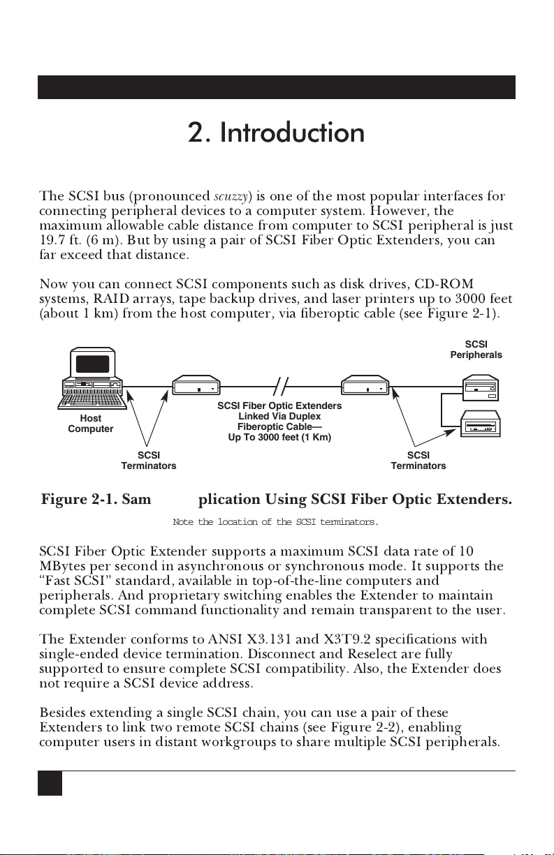
Now you can connect SCSI components such as disk drives, CD-ROM
systems, RAID arrays, tape backup drives, and laser printers up to 3000 feet
(about 1 km) from the host computer, via fiberoptic cable (see Figure 2-1).
Figure 2-1. Sample Application Using SCSI Fiber Optic Extenders.
Note the location of the SCSI terminators.
SCSI Fiber Optic Extender supports a maximum SCSI data rate of 10
MBytes per second in asynchronous or synchronous mode. It supports the
“Fast SCSI” standard, available in top-of-the-line computers and
peripherals. And proprietary switching enables the Extender to maintain
complete SCSI command functionality and remain transparent to the user.
The Extender conforms to ANSI X3.131 and X3T9.2 specifications with
single-ended device termination. Disconnect and Reselect are fully
supported to ensure complete SCSI compatibility. Also, the Extender does
not require a SCSI device address.
Besides extending a single SCSI chain, you can use a pair of these
Extenders to link two remote SCSI chains (see Figure 2-2), enabling
computer users in distant workgroups to share multiple SCSI peripherals.
2. Introduction
SCSI
Terminators
SCSI
Terminators
Host
Computer
SCSI
Peripherals
SCSI Fiber Optic Extenders
Linked Via Duplex
Fiberoptic Cable—
Up To 3000 feet (1 Km)
Page 5
5
CHAPTER 2: Introduction
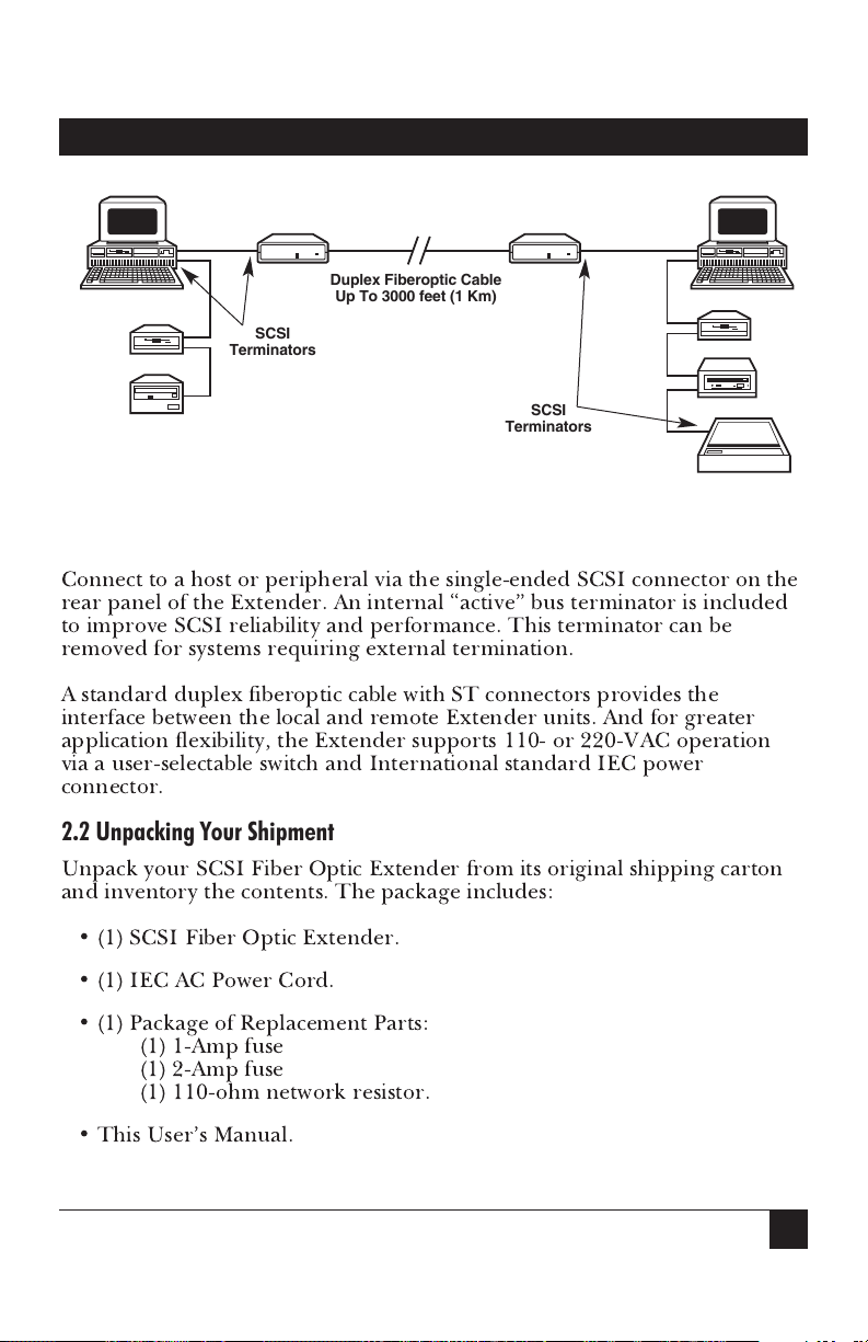
Figure 2-2. Sample Application Using SCSI Fiber Optic Extenders.
Note the location of the SCSI terminators.
Connect to a host or peripheral via the single-ended SCSI connector on the
rear panel of the Extender. An internal “active” bus terminator is included
to improve SCSI reliability and performance. This terminator can be
removed for systems requiring external termination.
A standard duplex fiberoptic cable with ST connectors provides the
interface between the local and remote Extender units. And for greater
application flexibility, the Extender supports 110- or 220-VAC operation
via a user-selectable switch and International standard IEC power
connector.
2.2 Unpacking Your Shipment
Unpack your SCSI Fiber Optic Extender from its original shipping carton
and inventory the contents. The package includes:
• (1) SCSI Fiber Optic Extender.
• (1) IEC AC Power Cord.
• (1) Package of Replacement Parts:
(1) 1-Amp fuse
(1) 2-Amp fuse
(1) 110-ohm network resistor.
• This User’s Manual.
SCSI
Terminators
Duplex Fiberoptic Cable
Up To 3000 feet (1 Km)
SCSI
Terminators
Page 6
6
SCSI Fiber Optic Extender
2.3 Operator Controls and Indicators
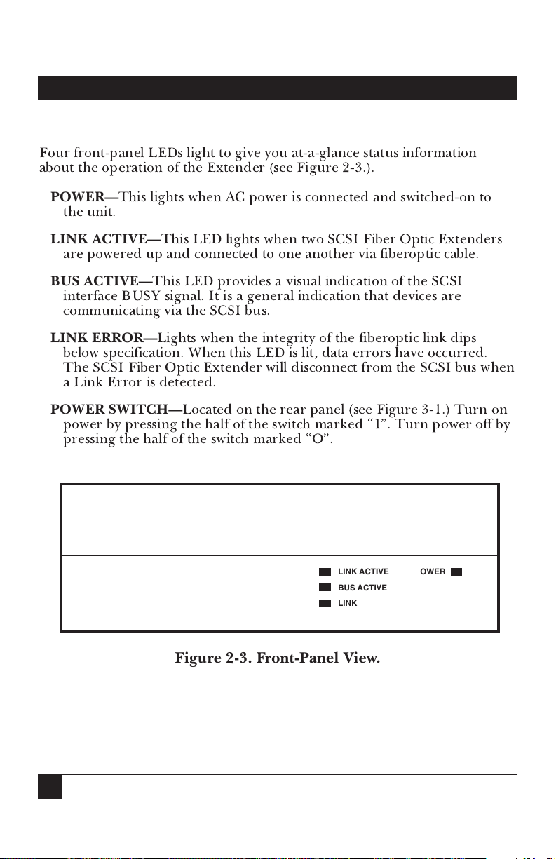
Four front-panel LEDs light to give you at-a-glance status information
about the operation of the Extender (see Figure 2-3.).
POWER—
This lights when AC power is connected and switched-on to
the unit.
LINK ACTIVE—
This LED lights when two SCSI Fiber Optic Extenders
are powered up and connected to one another via fiberoptic cable.
BUS ACTIVE—
This LED provides a visual indication of the SCSI
interface BUSY signal. It is a general indication that devices are
communicating via the SCSI bus.
LINK ERROR—
Lights when the integrity of the fiberoptic link dips
below specification. When this LED is lit, data errors have occurred.
The SCSI Fiber Optic Extender will disconnect from the SCSI bus when
a Link Error is detected.
POWER SWITCH—
Located on the rear panel (see Figure 3-1.) Turn on
power by pressing the half of the switch marked “1”. Turn power off by
pressing the half of the switch marked “O”.
Figure 2-3. Front-Panel View.
LINK ACTIVE
BUS ACTIVE
LINK ERROR
POWER
Page 7

7
CHAPTER 2: Introduction
2.4 Calling Your Supplier
If the Extender arrives incomplete, or subsequently malfunctions,
do not
attempt to alter or repair the unit
. It contains no user-serviceable parts. Contact
your supplier. Before you do, make a record of the history of the problem.
Your supplier will be able to provide more efficient and accurate assistance
if you have a complete description, including:
• The nature and duration of the problem.
• When the problem occurs.
• The components involved in the problem.
• Any particular application that, when used, appears to create the
problem or make it worse.
2.5 Shipping and Packaging
If you need to transport or ship your SCSI Fiber Optic Extender:
• We recommend that you use the original packaging container.
• If you are shipping the unit for repair, make sure you include its power
supply. If you are returning it, make sure you include this manual as
well. Before you ship, contact your supplier to get a Return Materials
Authorization (RMA) number.
Page 8
8
SCSI Fiber Optic Extender
The SCSI Fiber Optic Extender requires no software configuration and
only nearby access to an AC electrical outlet for proper operation. That
makes installation fast and easy.
Install the Extender in any position and any location near the host
computer or peripherals that’s most convenient for you. Make sure that the
ventilation slots on the side of the unit are unobstructed and receive
adequate air flow.
Do not
place the Extender on any device that generates
heat.
NOTE
Switch off power to all computers and peripherals attached to the SCSI bu s
before installing the SCSI Fiber Optic Extender.
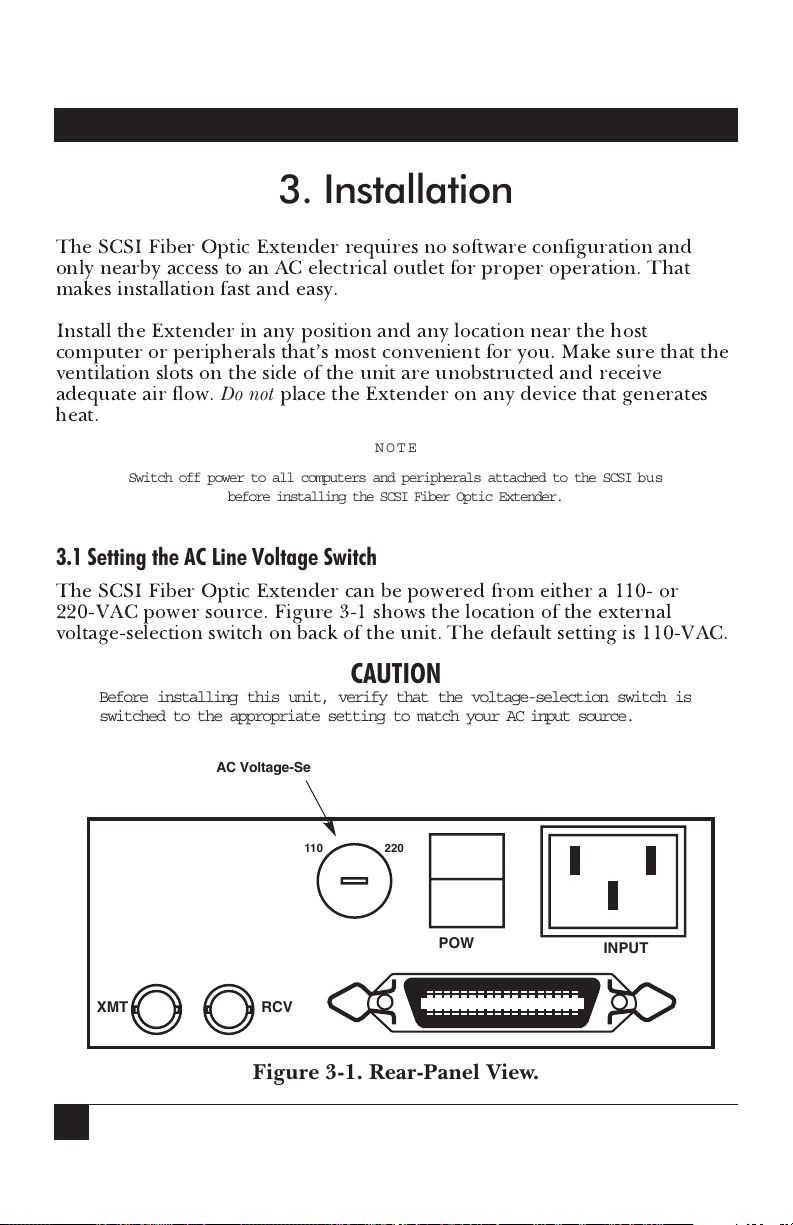
3.1 Setting the AC Line Voltage Switch
The SCSI Fiber Optic Extender can be powered from either a 110- or
220-VAC power source. Figure 3-1 shows the location of the external
voltage-selection switch on back of the unit. The default setting is 110-VAC.
CAUTION
Before installing this unit, verify that the voltage-selection switch is
switched to the appropriate setting to match your AC input source.
Figure 3-1. Rear-Panel View.
POWER
O
I
AC INPUT
RCV
XMT
220110
3. Installation
AC Voltage-Selection Switch
Page 9

9
With the voltage-selection switch set properly, plug the female end of the
power cord into the back of the unit and plug the male end of the cord into
your AC power outlet.
3.2 Recommended Cable
Twisted-Pair Cable—
A 50-pin shielded cable and connector will provide a
connection with the greatest noise immunity and distance from your host or
peripheral to the SCSI Fiber Optic Extender. But note that this cable
connection may never exceed 6 feet (19.7 m).
Section 3.5
describes
requirements for connecting to the SCSI Bus.
Appendix B
shows the
standard SCSI connector pinning chart.
Fiberoptic Cable—
Up to 3000 feet (about 1 km) of standard, full-duplex
multimode 62.5/125 µm, 100/140 µm, or 50/125 µm fiberoptic cable.
Improper connector termination, splicing of the fiberoptic cable, or use of
other cable diameters will result in reduced link distances and increased
data error rates.
Neither of these cables are included with this unit. Call your supplier to
order them separately.
3.3 Internal/External Terminator Options
The SCSI Fiber Optic Extender features internal active SCSI bus
termination to improve the cable-matching characteristics between multiple
SCSI devices. Since some applications require external terminators, you
may remove these internal terminators for added application flexibility.
To remove the internal terminators, remove the four screws on the bottom
of the unit (see
Figure 3-2
) and gently unplug terminators RN1, RN2, and
RN3 from their positions on the printed circuit board (PCB)
(see
Figure 3-3
).
Normally, terminators should be installed on opposite ends of the SCSI bus.
Note that data errors may result if more than two sets of terminators are
installed on any SCSI bus.
3.4 Internal Terminator Power and Fuse
The SCSI Fiber Optic Extender contains a replaceable internal fuse to
provide power for an external terminator. This fuse supplies 1 amp at
5 volts to the TERMPWR signal. The fuse is installed in the socket labeled
F2 on the PCB (see
Figure 3-3
). The Extender contains internal protection
and will not be affected if other SCSI devices provide terminator power.
CHAPTER 3: Installation
Page 10

10
SCSI Fiber Optic Extender
Figure 3-2. Remove Four Bottom-Panel Screws to Access the PCB.
3.5 Connecting to the SCSI Bus
The SCSI Fiber Optic Extender provides a transparent, optically isolated
SCSI bus over extended distances, so you can install the Extender at any
point on your SCSI bus. Terminators must be installed on both the local
and extended bus, so make sure that a maximum of two terminators are
installed on each side of the Extender link (see
Figures 2-1
and
2-2
).
Connect the twisted-pair cable from the host or SCSI peripheral to the
50-pin SCSI connector on back of the Extender. Use the bail-locking
mechanism to anchor the connection securely.
NOTE
If external termination is required, be sure to remove the internal termination
networks and replace them with an internal terminator fuse F2 (included).
(See Figures 3-2. and 3-3.).
MODEL NO:
SERIAL NO:
INPUT VOLTAGE 110/220VAC
ACI– 2000A
2003100
1
2
3
4
Page 11
11
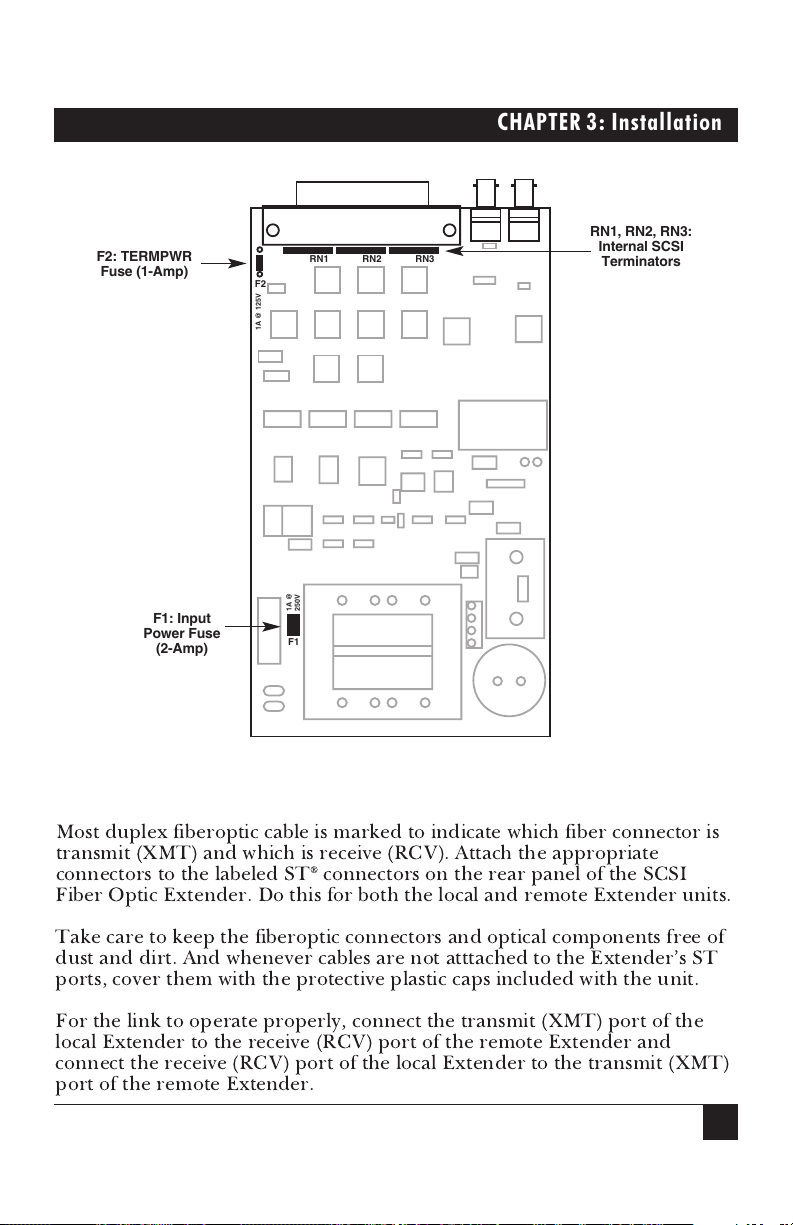
Figure 3-3. Location of the Internal Fuses and Terminators.
3.6 Connecting the Fiberoptic Cable
Most duplex fiberoptic cable is marked to indicate which fiber connector is
transmit (XMT) and which is receive (RCV). Attach the appropriate
connectors to the labeled ST®connectors on the rear panel of the SCSI
Fiber Optic Extender. Do this for both the local and remote Extender units.
Take care to keep the fiberoptic connectors and optical components free of
dust and dirt. And whenever cables are not atttached to the Extender’s ST
ports, cover them with the protective plastic caps included with the unit.
For the link to operate properly, connect the transmit (XMT) port of the
local Extender to the receive (RCV) port of the remote Extender and
connect the receive (RCV) port of the local Extender to the transmit (XMT)
port of the remote Extender.
F1
1A @
250V
F2
1A @ 125V
RN1 RN2 RN3
CHAPTER 3: Installation
F1: Input
Power Fuse
(2-Amp)
F2: TERMPWR
Fuse (1-Amp)
RN1, RN2, RN3:
Internal SCSI
Terminators
Page 12

12
SCSI Fiber Optic Extender
To identify unmarked fiber connectors, attach both connectors at one end
of the cable to the SCSI Fiber Optic Extender and then switch on power to
the unit. Then visually examine both connectors at the opposite end of the
cable to determine which one is the transmit fiber. A faint red light will be
visible at the tip of one of the connectors. This indicates the transmit fiber.
This is the connector that should be attached to the receive (RCV) port of
the remote Extender unit.
3.7 Verify the Connection
Switch on power to both SCSI Fiber Optic Extenders and verify that the
LINK ACTIVE LEDs are lit on the front panels of both units. This confirms
that the local and remote units are communicating.
You may now switch on power to your attached computers and peripherals.
Page 13

13
CHAPTER 4: Operation
4.1 Overview
The SCSI Fiber Optic Extender converts SCSI data and command
information into a serial data stream that’s transmitted over a high-speed
(175-Mhz) fiberoptic interface to the remote Extender. The remote unit
decodes the data stream and reconverts it back into proper SCSI signals.
The fiberoptic serial link conforms to the ANSI X3T9.5 encoding scheme
specified in FDDI local area networks and is virtually immune to all forms
of radio-frequency and electromagnetic interferences (RFI/EMI). An
unauthorized tap of the link is nearly impossible without detection.
4.2 System Performance
The SCSI Fiber Optic Extender will support any combination of
asynchronous and synchronous SCSI devices on the bus. Overall system
performance will depend on the individual data rate and protocol of each
SCSI device plus the overhead of the host computer.
In general, devices connected via a SCSI Fiber Optic Extender link up to
300 feet ( about 100 m) will achieve aggregate data rates of 225 kilobytes
per second in asynchronous mode. In synchronous mode, with a byte offset
of 8, sustainable data rates of 4 megabytes per second can be expected. A
synchronous offset of 16 will provide 5 megabytes per second data rates.
4.3 System Configuration Options
The SCSI Fiber Optic Extender supports a maximum data rate of 10
megabytes per second. This data rate is often referred to as Fast SCSI. To
ensure optimum system performance, some system configurations may
require a secondary SCSI channel to interface with the Extender (see
Figure
4-1
).
4. Operation
Page 14

14
SCSI Fiber Optic Extender
Figure 4-1. Alternate Configuration Linking Two SCSI Buses.
In this configuration, the primary SCSI bus is used to connect the local
high-speed peripherals. The secondary SCSI bus is used exclusively as the
extended SCSI bus.
Fiberoptic Cable
Primary
SCSI Bus
Terminators
Terminator
Secondary
SCSI Bus
Terminator
Page 15
15
APPENDIX A: SCSI Signal Descriptions
A total of 18 signals are required for the SCSI interface. These signals are
described as follows:
BSY (BUSY)—
An “OR-tied” signal indicating that the bus is being used.
SEL (SELECT)—
An “OR-tied” signal used by an initiator to select a target
or by a target to reselect an initiator.
C/D (CONTROL/DATA)—
A signal driven by a target that indicates
whether CONTROL or DATA information is on the DATA BUS. True
indicates CONTROL.
I/O (INPUT/OUTPUT)—
A signal driven by a target that controls the
direction of data movement on the DATA BUS with respect to an initiator.
True indicates input to the initiator. This signal is also used to distinguish
between SELECTION and RESELECTION phases.
MSG (MESSAGE)—
A signal driven by a target during the MESSAGE phase.
REQ (REQUEST)—
A signal driven by a target to indicate a request for a
REQ/ACK data transfer handshake.
ACK (ACKNOWLEDGE)—
A signal driven by an initiator to indicate an
acknowledgement for a REQ/ACK data transfer handshake.
ATN (ATTENTION)—
A signal driven by an initiator to indicate the
ATTENTION condition.
RST (RESET)—
An “OR-tied” signal that indicates the RESET condition.
DB(7-0,P) (DATA BUS)—
Eight data-bit signals, plus a parity-bit signal that
form a DATA BUS. DB(7) is the most significant bit and has the highest
priority during the ARBITRATION phase. Bit number, significance, and
priority decrease downward to DB(0). A data bit is defined as one when the
signal value is true and is defined as zero when the signal value is false. Data
parity DB(P) shall be odd.
Appendix A—SCSI Signal Descriptions
Page 16

16
SCSI Fiber Optic Extender
CONNECTOR PIN NUMBER CONNECTOR PIN NUMBER
SIGNAL NAME UNSHIELDED SHIELDED SIGNAL NAME UNSHIELDED SHIELDED
-DB(0) 2 26 GROUND 1 1
-DB(1) 4 27 GROUND 3 2
-DB(2) 6 28 GROUND 5 3
-DB(3) 8 29 GROUND 7 4
-DB(4) 10 30 GROUND 9 5
-DB(5) 12 31 GROUND 11 6
-DB(6) 14 32 GROUND 13 7
-DB(7) 16 33 GROUND 15 8
-DB(P) 18 34 GROUND 17 9
GROUND 20 35 GROUND 19 10
GROUND 22 36 GROUND 21 11
GROUND 24 37 GROUND 23 12
TERMPWR 26 38 OPEN 25 13
GROUND 28 39 GROUND 27 14
GROUND 30 40 GROUND 29 15
-ATN 32 41 GROUND 31 16
GROUND 34 42 GROUND 33 17
-BSY 36 43 GROUND 35 18
-ACK 38 44 GROUND 37 19
-RST 40 45 GROUND 39 20
-MSG 42 46 GROUND 41 21
-SEL 44 47 GROUND 43 22
-C/D 46 48 GROUND 45 23
-REQ 48 49 GROUND 47 24
-I/O 50 50 GROUND 49 25
Appendix B—SCSI Connector Pinning
Page 17

®
P.O. Box 12800 • Pittsburgh, PA 15241 • (412) 746-5500 • Fax (412) 746-0746
© Copyright 1996. Black Box Corporation. All rights reserved.
Black Box Corporation
The Source for Connectivity
®
 Loading...