

Page 1
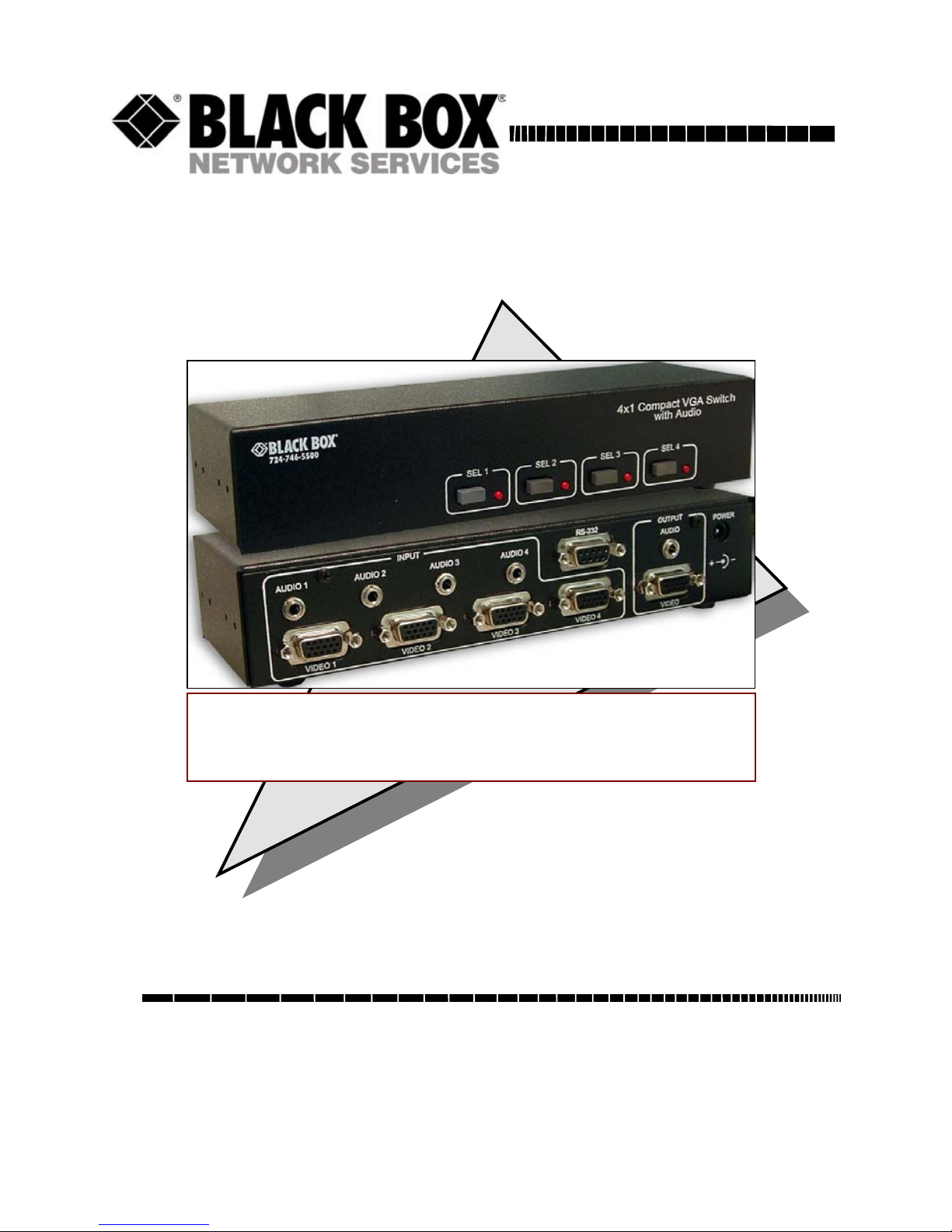
• Switches Between 4 PC Video and Audio Signals
• Manual or Auto Switching Based on Active Video
• RS-232 Serial Control
4x1 Compact VGA Switch w/Audio
AC506A-4A
Order toll-free in the U.S. 24 hours, 7 A.M. Monday to midnight Friday: 877-877-BBOX
FREE technical support, 24 hours a day, 7 days a week: Call 724-746-5500 or fax 724-746-0746
Mail order: Black Box Corporation, 1000 Park Drive, Lawrence, PA 15055-1018
Web site: www.blackbox.com • E-mail: info@blackbox.com
CUSTOMER
SUPPORT
INFORMATION
UMA1124
Rev B
Page 2

Page 3

4x1 Compact VGA Switch w/ Audio
1
Trademarks Used in this Manual
BLACK BOX and its logo are registered trademarks of Black Box
Corporation. HDMI is a registered trademark of HDMI Licensing
LLC.
Any other trademarks mentioned in this manual are acknowledged to be
the property of the trademark owners.
FCC and Canadian Dept of Communications Radio
Frequency interference statements
This equipment generates, uses, and can radiate radio frequency
energy and if not installed and used properly, that is, in strict
accordance with the manufacturer’s instructions, may cause
interference to radio communication. It has been tested and found
to comply with the limits for a Class A computing device in
accordance with the specifications in Subpart B of Part 15 of FCC
rules, which are designed to provide reasonable protection against
such interference when the equipment is operated in a
commercial environment. Operation of this equipment in a
residential area is likely to cause interference, in which case the
user at their own expense will be required to take whatever
measures may be necessary to correct the interference. Changes
or modifications not expressly approved by the party responsible
for compliance could void the user’s authority to operate the
equipment.
This digital apparatus does not exceed the Class A limits for radio
noise emission from digital apparatus set out in the Radio
Interference Regulation of the Canadian Department of
Communications.
Le présent appareil numérique n’émet pas de bruits
radioélectriques dépassant les limites applicables aux appareils
numériques de la classe A prescrites dans le Règlement sur le
brouillage radioélectrique publié par le ministère des
Communications du Canada.
European Union Declaration of Conformity
This product complies with the requirements of the European EMC
directive 89/336/EEC
Page 4

Model AC506A-4A
2
Page 5

4x1 Compact VGA Switch w/ Audio
3
Normas Oficiales Mexicanas (NOM)
Electrical Safety Statement
INSTRUCCIONES DE SEGURIDAD
1. Todas las instrucciones de seguridad y operación deberán ser leídas antes de
que el aparato eléctrico sea operado.
2. Las instrucciones de seguridad y operación deberán ser guardadas para
referencia futura.
3. Todas las advertencias en el aparato eléctrico y en sus instrucciones de
operación deben ser respetadas.
4. Todas las instrucciones de operación y uso deben ser seguidas.
5. El aparato eléctrico no deberá ser usado cerca del agua—por ejemplo, cerca
de la tina de baño, lavabo, sótano mojado o cerca de una alberca, etc.
6. El aparato eléctrico debe ser usado únicamente con carritos o pedestales que
sean recomendados por el fabricante.
7. El aparato eléctrico debe ser montado a la pared o al techo sólo como sea
recomendado por el fabricante.
8. Servicio—El usuario no debe intentar dar servicio al equipo eléctrico más allá a
lo descrito en las instrucciones de operación. Todo otro servicio deberá ser
referido a personal de servicio calificado.
9. El aparato eléctrico debe ser situado de tal manera que su posición no
interfiera su uso. La colocación del aparato eléctrico sobre una cama, sofá,
alfombra o superficie similar puede bloquea la ventilación, no se debe colocar
en libreros o gabinetes que impidan el flujo de aire por los orificios de
ventilación.
10. El equipo eléctrico deber ser situado fuera del alcance de fuentes de calor
como radiadores, registros de calor, estufas u otros aparatos (incluyendo
amplificadores) que producen calor.
11. El aparato eléctrico deberá ser connectado a una fuente de poder sólo del tipo
descrito en el instructivo de operación, o como se indique en el aparato.
12. Precaución debe ser tomada de tal manera que la tierra fisica y la polarización
del equipo no sea eliminada.
13. Los cables de la fuente de poder deben ser guiados de tal manera que no
sean pisados ni pellizcados por objetos colocados sobre o contra ellos,
poniendo particular atención a los contactos y receptáculos donde salen del
aparato.
14. El equipo eléctrico debe ser limpiado únicamente de acuerdo a las
recomendaciones del fabricante.
15. En caso de existir, una antena externa deberá ser localizada lejos de las lineas
de energia.
16. El cable de corriente deberá ser desconectado del cuando el equipo no sea
usado por un largo periodo de tiempo.
17. Cuidado debe ser tomado de tal manera que objectos liquidos no sean
derramados sobre la cubierta u orificios de ventilación.
18. Servicio por personal calificado deberá ser provisto cuando:
A: El cable de poder o el contacto ha sido dañado; u
B: Objectos han caído o líquido ha sido derramado dentro del aparato; o
C: El aparato ha sido expuesto a la lluvia; o
D: El aparato parece no operar normalmente o muestra un cambio en su
desempeño; o
E: El aparato ha sido tirado o su cubierta ha sido dañada.
.
Page 6

Model AC506A-4A
4
Contents
1. INTRODUCTION ......................................................................5
1.1 GENERAL ..............................................................................5
1.2 FEATURES.............................................................................5
2. INSTALLATION........................................................................6
2.1 REQUIRED CABLES ................................................................6
2.2 INPUTS & OUTPUTS ...............................................................6
2.3 CONNECTING THE AC506A-4A ..............................................6
2.4 CONNECTION DIAGRAM..........................................................7
3. CONFIGURATION & OPERATION .........................................8
3.1 MODES OF OPERATION ..........................................................8
3.2 FRONT-PANEL SWITCHES ......................................................9
3.3 RS-232 CONTROL...............................................................10
3.4 SERIAL PORT CONTROL CODES ...........................................11
4. TROUBLESHOOTING ...........................................................14
4.1 IN CASE OF TROUBLE...........................................................14
4.2 CALLING BLACK BOX ...........................................................14
4.3 SHIPPING AND PACKAGING...................................................14
5. SPECIFICATIONS..................................................................15
Page 7

4x1 Compact VGA Switch w/ Audio
5
1. Introduction
1.1 General
Thank you for purchasing Black Box AC506A-4A 4x1 Compact
VGA Switch with Audio & Serial Control.
This unit provides a video along with audio output that can be
switched between four video and audio sources. The unit is
housed in a small RFI shielded enclosure and is supplied with a
universal AC power adapter.
The AC506A-4A unit provides all the A/V and control connections
on the rear panel; the front panel has push-button switches with
corresponding LED indicators for the selection of the video
source. This unit can be controlled either manually using the front
panel switches, automatically based on video detection, or
remotely through an RS232 serial port.
The unit can be configured to operate in three different modes,
which are: Auto, Scan and Normal. There is a priority selection
that can be used to set for the video inputs. The switched output
can be blanked and un-blanked from the PC command sent
through the serial port. The front-panel buttons can be ‘locked’ to
prevent accidental changes to the settings from a PC command
sent through the serial port.
The unit also has EEPROM (internal non-volatile flash memory) to
restore the last operating mode from when the unit is powered off.
1.2 Features
Allows four video & stereo audio input sources to be
switched to one output
Can be manually controlled by push-button, via RS232
communication port or by detecting active video input
Auto mode automatically scans and selects the input with
active video with selectable input priorities
Front panel buttons can be ‘Locked’ out
Switched output can be blanked and un-blanked
Stores the last selection and mode in EEPROM
In scanning mode inputs are shown for pre-determined
periods
Ships with universal (100~240 VAC) power supply
Compact, Rugged, Reliable, and Economical
Page 8

Model AC506A-4A
6
2. Installation
2.1 Required Cables
The video input cables are generally HD15 (VGA) male to male
(customer furnished). The Audio inputs are 3.5 mm mini-stereo
plugs (customer furnished). If you are going to connect the unit to
a Serial port (such as PC’s COM) you would need a straightthrough Male/Female DB9 Serial Cable (customer furnished).
2.2 Inputs & Outputs
The AC506A-4A has 4 video and audio inputs marked Video 1
through 4 and Audio 1 through 4. The unit has 1 video and audio
output marked Video and Audio Output. The unit has 1 serial port
connector labeled RS232.
2.3 Connecting the AC506A-4A
Connect your video and audio sources such as computer or
notebook PC to any of the Video and Audio Inputs 1 through 4.
Connect the display device such as a monitor (or a video
projector) to the switched video and audio outputs (Video and
Audio Output).
Connect the included power supply to the AC506A-4A.
Select the desired video source or mode of operation for your
video and audio output using the front panel switched buttons. If
preferred, the selection can also be done through RS-232 serial
commands by connecting a DB9 RS-232 Serial cable to your PC
and the AC506A-4A.
Page 9

4x1 Compact VGA Switch w/ Audio
7
2.4 Connection Diagram
Page 10

Model AC506A-4A
8
3. Configuration & Operation
3.1 Modes of Operation
Auto Mode - This will select the VGA and Audio input with
the highest priority that has an active VGA signal.
Scan Mode - Will select each active VGA and Audio input
signal for a specified number of seconds, 1-60, and then
switch to the next active VGA input. The AC506A-4A can also
be configured to scan the non-active VGA inputs as well as
the active VGA inputs.
Normal Mode - VGA inputs are selected based on front
panel push-button selections.
The AC506A can only be in one of these modes at a time. You
can specify mode of operation either from the Serial port or from
the front panel (by pressing switch combinations simultaneously).
Pressing SEL 1 & SEL 2 simultaneously selects “AUTO”
mode.
Pressing SEL 3 & SEL 4 simultaneously selects “SCAN”
mode.
The AC506A-4A retains the last mode that it was in after power off
and upon power up, will enter the last mode that it was in.
Page 11

4x1 Compact VGA Switch w/ Audio
9
3.2 Front-Panel Switches
The front panel switches may be locked out so pressing them has
no effect. Locking and unlocking the front panel switches can only
be accomplished via the serial RS-232 commands.
The first function of the front panel buttons is to switch from one
VGA & Audio signal to another. Just press the button and the VGA
signal you selected will be displayed when the front panel is not
locked. If there is no VGA signal to be displayed then you will see
a black screen. The AC506A-4A will enter the Normal Mode any
time a single front panel button is pressed and the front panel is
not locked.
The second use of the front panel buttons is to put the AC506A-4A
into Auto Mode. Press buttons 1 and 2 simultaneously and the
AC506A-4A will enter the Auto Mode when the front panel is not
locked.
The third use of the front panel buttons is to put the AC506A-4A
into Scan Mode. Press buttons 3 and 4 simultaneously and the
AC506A-4A will enter the Scan Mode when the front panel is not
locked.
The time interval between switching will be the time interval last
specified via the serial port. If no interval has been specified via
the RS232 port then the default is 5 seconds.
Whether or not to scan non-active VGA inputs along with active
VGA inputs will be determined from the last user input via serial
port as well. If there has been no user input, the default is to not
scan the non-active VGA inputs.
Page 12

Model AC506A-4A
10
3.3 RS-232 Control
The AC506A-4A can also be controlled via a serial device. The
unit operates at a baud rate of 4800 bps. From the serial port, you
have full control over the operation of the switched output; mode,
priorities, scan time and front-panel lock status.
Note on RS-232 port availability on your PC
Most PCs and notebooks do not have a serial port. So to program
the Switch you may need a USB to RS-232 Serial converter. Please
contact your Black Box sales representative if you need to buy one.
The AC506A-4A will output a menu to a serial port on power-up.
This menu will also be displayed when a “List” command is sent to
it via a serial port. To view the menu, An ASCII serial terminal or
terminal emulator software is needed. An example is Microsoft
Windows HyperTerminal (generally found in
Accessories\Communication folder)
. To configure HyperTerminal
- Connect direct to any available COM port
- 4800 Baud, 8 bits, No Parity, 1 Stop bit, No flow
control
Page 13

4x1 Compact VGA Switch w/ Audio
11
After power-up the unit will output the following menu in ASCII
through its serial port:
3.4 Serial Port Control Codes
(1 byte commands from external control device)
ASCII 1 (or Hex 31)
Selects Video input #1
ASCII 2 (or Hex 32)
Selects Video input #2
ASCII 3 (or Hex 33)
Selects Video input #3
ASCII 4 (or Hex 34)
Selects Video input #4
Ver1.0
-----1 = #1 In
2 = #2 In
3 = #3 In
4 = #4 In
a = Auto mode
s = Scan
b = Blank
u = Un-Blank
p = Priorities
r = Reset
Page 14

Model AC506A-4A
12
ASCII a (or Hex 61)
Enters ‘Auto’ mode.
In Auto mode, the device automatically switches to the
video & audio input source that is active. “Active” means
that video signal has sync signal, it does not mean there is
a non-static screen!
ASCII s (or Hex 73)
Enters ‘Scan’ Mode.
The user is first prompted to enter the switching time
delay from 1-60 seconds.
“Seconds between switching? (1-60)”
The users are then prompted to select whether ‘nonactive’ video input channels should be scanned or not.
“Scan non-active? (Y/n)”
ASCII b (or Hex 62)
Blanks the output. When the output is blanked, only the
color intensities of the output are reduced to zero
(resulting in a black screen), the unit still operates in
normal fashion and sync signals are still routed to the
output. Audio output is muted.
ASCII u (or Hex 75)
Un-blanks the output.
Page 15

4x1 Compact VGA Switch w/ Audio
13
ASCII p (or Hex 70)
Selects video input priorities.
The device will ask for the priorities for each of the four
inputs via a prompt the user must respond to.
“In X is [Y] (1-4)?” Where ‘X’ is the Video input and ‘Y’
is its current priority.
Entering ‘0’ for a video input priority will keep the existing
priority.
Priority can range from 1 to 4, 1 being the highest and 4
being the lowest.
For example, if Video #1 priority is set at 1, the unit will
select input #1 automatically whenever the presence of
the video at Video 1 input is detected even if the input
from the Video 2 input is currently playing. If no video is
detected for a specific video input, the next video input is
selected based on the priority setting in order.
ASCII r (or Hex 72)
Reset the unit back to factory defaults.
Priorities are set to 1,2,3,4
Scan time is set to 5 seconds
Front panel is unlocked
ASCII l (or Hex 6c)
Toggles the Front Panel key lock setting.
Page 16

Model AC506A-4A
14
4. Troubleshooting
4.1 In Case of Trouble
There are no field serviceable parts or circuits in the device. If you
think that the device is malfunctioning, please first make sure that
all your connections are solid, and check the state of the LED’s on
the front of the unit to access the mode it is in.
If you still cannot overcome the problem, disconnect the video and
audio input connections from the unit. Unplug the power from the
unit and after a few seconds reconnect power. Connect your audio
and video signals after the unit is powered up. Check
performance.
4.2 Calling Black Box
If you determine that your unit is malfunctioning, do not attempt to
repair the unit. Contact Black Box Tech. Support at 724-746-5500.
Before you do, make a record of the history of the problem. We
will be able to provide more efficient and accurate assistance if
you have a complete description, including:
• The nature and duration of the problem;
• The components involved in the problem—that is, what type
of cable, makes and models of computers and monitors, etc.
• The results of any testing you’ve already done.
4.3 Shipping and Packaging
If you need to transport or ship your AC506A-4A:
• Package it carefully. We recommend that you use the original
container.
• Before you ship the unit back to Black Box for repair or return,
contact us to get a Return Authorization (RA) number.
Page 17

4x1 Compact VGA Switch w/ Audio
15
5. Specifications
Video Inputs VGA, RGBHV, RGBS, RGsB, or Component Video
(YPbPr – would require HD15 to 3 RCA adapter)
Resolutions
Supported PC from VGA to UXGA (640x480 to 1600x1200)
HD from 480p to 1080p
Audio Inputs PC or Consumer audio (standard line-level)
Video Level 0 to 0.7V p-p on RGB, 0 to 5 V for H and V Sync
Bandwidth 200 MHz
Max Altitude 10,000 ft (3048 meters)
Temperature Operating: 32 to 122°F (0 to 50°C);
Storage: –40 to +185°F (–40 to +85°C)
Humidity Up to 95% non-condensing
Enclosure Steel
MTBF 90,000 hours (calculated estimate)
Power 6V center positive via supplied Universal power
supply (100~240VAC).
Size 1.7”(43mm) H x 8.42"(213mm) W x 2.75”(70mm) D
Weight 2.0 pounds (800 grams) Shipping
Page 18

Model AC506A-4A
16
Page 19

4x1 Compact VGA Switch w/ Audio
17
Page 20

Page 21

© Copyright 2007. Black Box Corporation. All rights reserved.
1000 Park Drive Lawrence, PA 15055-1018 724-746-5500 Fax 724-746-0746
 Loading...