

Page 1
CUSTOMER
SUPPORT
INFORMATION
Order toll-free in the U.S. 24 hours, 7 A.M. Monday to midnight Friday: 877-877-BBOX
FREE technical support, 24 hours a day, 7 days a week: Call 724-746-5500 or fax 724-746-0746
Mail order: Black Box Corporation, 1000 Park Drive, Lawrence, PA 15055-1018
Web site: www.blackbox.com • E-mail: info@blackbox.com
MARCH 1994
AC461C
PC Image II
Page 2

1
PC IMAGE II
FEDERAL COMMUNICATIONS COMMISSION
RADIO FREQUENCY INTERFERENCE STATEMENT
This equipment generates, uses, and can radiate radio frequency energy
and if not installed and used properly, that is, in strict accordance with the
manufacturer's instructions, may cause interference to radio communication.
It has been tested and found to comply with the limits for a Class B
computing device in accordance with the specifications in Subpart J of
Part 15 of FCC Rules, which are designed to provide reasonable protection
against such interference when the equipment is operated in a commercial
environment. Operation of this equipment in a residential area is likely to
cause interference, in which case the user at his own expense will be required
to take whatever measures may be required to correct the interference.
Changes or modifications not expressly approved by the party responsible
for compliance could void the user's authority to operate the equipment.
This digital apparatus does not exceed the Class B limits for Radio noise emission from
digital apparatus set out in the Radio Interference Regulation of Industry Canada .
Le présent appareil numérique n'émet pas de bruits radioélectriques dépassant les
limites applicables aux appareils numériques de la classe B prescrites dans le Règlement
sur le brouillage radioélectrique édicté par Industrie Canada.
TRADEMARKS
Windows™is a trademark, and Microsoft®is a registered trademark
of Microsoft Corporation.
PostScript®is a registered trademark of Adobe Systems Incorporated.
IBM®and AT®are registered trademarks of IBM Corporation.
RCA®is a registered trademark of General Electric Co.
Sound Blaster™is a trademark of Creative Labs, Inc.
Sony®is a registered trademark of Sony Corporation.
Novell®is a registered trademark of Novell Corporation.
All applied-for and registered trademarks are the property of their respective
owners.
Page 3

2
PC IMAGE II
Contents
1. INTRODUCTION ...................................................................................5
1.1 Block Diagram of PC Image.......................................................5
1.2 PC IMAGE II Functions .............................................................7
1.3 System Requirements .................................................................7
2. QUICK INSTALL ....................................................................................8
2.1 Install the Hardware...................................................................8
2.2 Connect External Devices to PC Image II.................................9
3. HARDWARE INSTALLATION ............................................................13
3.1 Hardware...................................................................................13
3.1.1 Set the CD-ROM Jumpers............................................15
3.1.2 Connect the Audio-Header .........................................15
3.1.3 Install the Audio Header Cover ..................................16
3.2 Attach PC Speaker Wires (Optional) ......................................16
3.3 Connecting SCSI CD-ROM Drives...........................................16
3.3.1 CD-ROM Drive Settings ..............................................17
3.3.2 Connecting the Data Cable .........................................17
3.3.3 Connecting the Audio Cable.......................................17
3.3.4 Reassemble the PC .......................................................17
3.4 Connecting to a Television Monitor .......................................18
3.4.1 RCA Plug (Video Out).................................................18
3.4.2 4-Pin DIN Plug (S-Video).............................................18
3.4.3 Cable Input (Antenna Input)......................................18
3.5 Protecting Your Sound Equipment .........................................18
4. SOFTWARE INSTALLATION..............................................................19
4.1 Installing DOS Drivers and Software.......................................19
4.2 Installation Procedures ............................................................19
4.3 CD-ROM Driver Setup..............................................................21
4.3.1 Using Your SCSI Driver................................................21
4.3.2 Optional Parameter .....................................................21
4.4 The MSCDEX Driver................................................................21
4.4.1 Optional Parameters ....................................................22
4.5 MVSOUND.SYS Driver.............................................................22
4.6 Changing the Volume Level ....................................................23
4.7 Changing Hardware Settings With A Text Editor ..................23
4.8 Installing the DOS Video Driver..............................................23
4.8.1 Flicker Reduction .........................................................23
4.8.2 Screen Position.............................................................23
4.9 Installing Windows Drivers ......................................................23
Page 4

3
PC IMAGE II
4.9.1 Installing MCI CD-Audio Drivers ................................24
4.9.2 Changing the Hardware Settings for Windows ..........25
4.9.3 Resolving DMA and IRQ Conflicts in DOS ................25
4.9.4 Understanding IRQs ....................................................25
4.9.5 Understanding DMA Channels...................................26
4.9.6 Conflicts With Other Programs...................................27
5. PAS UTILITY 28
5.1 Introduction to PAS ................................................................28
5.2 Mixer Control Panel.................................................................29
5.3 Command Line Mixer Control................................................31
5.3.1 PAS Keywords ...............................................................31
5.3.2 Help...............................................................................32
5.4 PAS Utility Examples................................................................33
5.4.1 Audio Source Input Level Control..............................33
5.4.2 Fading ...........................................................................34
5.4.3 Equalizer Control (Enhancements)............................34
5.5 Master Volume Control............................................................35
5.6 Mute .......................................................................................35
5.7 Queue Control..........................................................................35
5.7.1 Reset Command ...........................................................36
5.8 Error Messages..........................................................................36
5.9 Playback and Record Utilities ..................................................36
5.9.1 PLAYFILE.EXE.............................................................37
5.9.2 RECFILE.EXE...............................................................38
6. WINDOWS UTILITIES.........................................................................39
6.1 Pro Mixer Utility .......................................................................39
6.1.1 Using the Multimedia Mixer Dialog Box....................40
6.1.2 Changing the Volume..................................................41
6.1.3 Set an Audio Source for Playing or Recording ..........41
6.1.4 Using the Equalizer......................................................42
6.1.5 Using the Timed Fade Dialog......................................43
6.1.6 Cross-Channel Fades ....................................................44
6.1.7 Mixer Setting Delays.....................................................44
6.2 Pocket Recorder .......................................................................45
6.2.1 File Menu Functions ....................................................46
6.2.2 Edit Functions ..............................................................47
6.2.3 Effects Functions ..........................................................48
6.3 Using Pocket Recorder ............................................................49
6.3.1 Selecting a Region of a Wavefile .................................49
6.3.2 Playing a Waveform File...............................................50
6.3.3 Recording a Waveform File .........................................51
Page 5

4
PC IMAGE II
6.3.4 OLE and Pocket Recorder...........................................53
6.3.5 Exiting From Pocket Recorder....................................54
6.4 Pocket Mixer Utility..................................................................54
6.4.1 Using Pocket Mixer......................................................54
6.4.2 Creating a MIX File......................................................56
6.4.3 Recording/Playback Considerations ..........................57
6.4.4 Recording with a Microphone.....................................57
6.4.5 Setting an Audio Source for
Playing or Recording....................................................57
6.5 Media Player .............................................................................57
7. VGA, TV, AND VIDEO PRIMER ..........................................................59
7.1 The Basics .................................................................................59
7.2 VGA Basics ................................................................................59
7.3 TV/Video Basics .......................................................................59
7.4 Converting VGA to Television .................................................60
7.5 Best Results on TV....................................................................60
7.6 Best Results on Videotape........................................................61
7.7 Audio and Video Output to TV or Videotape ........................61
7.7.1 Record to Videotape ....................................................61
8. TROUBLESHOOTING ........................................................................62
8.1 Poor Sound or No Sound ........................................................62
8.2 CD-ROM and Disk Drive Problems .........................................64
8.3 System Hang-Ups or Lock-Ups ................................................65
8.4 Windows Questions ..................................................................65
8.5 Video Questions........................................................................66
APPENDIX A: TECHNICAL INFORMATION ...............................................68
A.1 I/O Addresses...........................................................................68
Page 6

5
CHAPTER 1: Introduction
With PC IMAGE II, you can convert
your PC’s VGA output to be
displayed on a television or recorded
to a VCR. This capability, combined
with PC IMAGE II’s complete sound
card functions, brings audio and
video production to your PC.
Please take a few minutes to read
this introduction carefully. It details
the use of this manual and the
functional blocks of the PC IMAGE
II; and provides a glimpse of the uses
for this innovative device.
1.1 Block Diagram of PC Image
There are several sections to the PC
Image board. The combination of
these parts is what gives the PC
IMAGE it’s unique capabilities.
With PC IMAGE II, you can record
audio onto your hard disk from a
microphone, CD, or external (AUX)
device. MIDI data can play the onboard FM synthesizer, or can be sent
to external synthesizers. All audio
sources can be mixed and modifed
via the mixer.
The video block of PC Image II takes
the external VGA signal and does
two things. First, it splits the signal
and passes part of it to the PC Image
II’s VGA port, for viewing on a VGA
monitor. Second, it connects the
signal to a televsion signal, and
sends it out to the PC IMAGE II’s
video out ports for recording and
display.
1. Introduction
Page 7

6
PC IMAGE II
1.2 PC Image II Functions
• Business Presentations — Your
PC IMAGE II gives you the power
to record, edit, and play back all
audio and video elements for a
dynamic and effective presentation, product demo, or
multimedia expereince.
Presentations can be recorded
to videotape for distribution, or
alternatively can be distributed
on floppy disk.
• MIDI — Your PC IMAGE II puts
a recording studio in your PC.
You can use your PC Image II
with the latest MIDI sequencer
software (optional) as well as
explore possibilities of hard disk
recording.
• MPC Compatible — The PC
IMAGE II meets or exceeds all
the specifications for the
Multimedia PC (MPC) platform.
It is fully compatible with the
Microsoft®Windows™graphical
environment with Multimedia
Extensions, Version 1.0 and
Windows 3.1, and all the
applications requiring an MPC
audio adapter.
• Audio Mixer — PC IMAGE II’s
high-fidelity audio mixer ties
together CD-audio, sequenced
MIDI synthesizers, digitally
sampled audio samples, and
external audio and plays them
through whatever playback
system you want. You can mix
all your sound sources to a single
stereo output; play sounds
together; and solo, or pan them
from one side of the stereo field
to the other.
PC IMAGE II CHAPTER 1: Introduction
1.3 System Requirements
Your PC must meet the following
minimum specifications for your PC
IMAGE II to work properly. If it does
not, you will need to upgrade the
deficient areas.
• IBM®AT®, 80286, 80386, 80486,
or other compatible
• 3.5" disk drive
• 640K RAM System Memory
• DOS 3.1 or higher
• Hard disk with 6 MB free space.
• Headphones (using a 1/8-inch
stereo phono plug)
Optional:
• Microphone (600 to 10K ohm
dynamic
• External audio source (tape
player, stereo, etc.)
MIDI interface cables and MIDI
sequencing software.
Page 8
7
PC IMAGE IICHAPTER 1: IntroductionPC IMAGE II CHAPTER 1: IntroductionPC IMAGE II
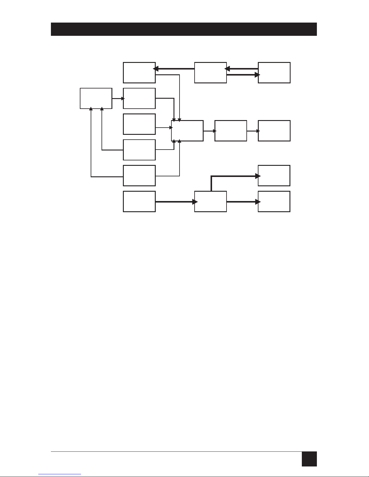
Figure 1-1. Block Diagram of PC IMAGE II.
FM
Synthesizer
MIDI
Controller
External
MIDI In/Out
Dig./Analog
Converter
(.WAV files)
CD-Audio
Output
Mic
Input
AUX
Input
VGA Card
Output
Analog/Dig.
Converter
VGA-Pass
Through
Output
NTSC
Output
VGA-NTSC
Module
Audio
Output
AmplifierMixer
Page 9

8
PC IMAGE II
This chapter is designed for people
who have a thorough under-standing
of both their PC and their video and
audio hardware. If you are not one
of these people, refer to the detailed
instructions beginning in Chapter 3.
2.1 Install the Hardware
Set the CD-ROM Jumpers
Your PC IMAGE II board includes
a CD-ROM interface. If you wish to
connect a CD-ROM drive, you will
have to set two jumpers. If you are
not using the CD-ROM interface, go
to the next heading.
Jumpers 15 and 16 set the IRQ level
and DMA channel for the PC
IMAGE II’s CD-ROM interface. Set
these so that they do not conflict
with other peripherals in your PC.
Connect the audio header cable.
Take this time to locate the audio
header. This unit is a long, flat,
ribbon cable with an expansion-slot
connector at one end. Plug this
cable into the back of the PC IMAGE
II board (see Figure 2-1). Pin 1 on
all of the board connectors is
indicated by a small triangle.
2. Quick Install
Figure 2-1. PC IMAGE II Board.
Page 10

9
CHAPTER 2: Quick Install
Install the board.
Remove the cover from your PC and
install the board in an unused 16-bit
expansion slot. Secure the card with
the screw from the PC’s expansion
slot cover.
Install the audio-header cover.
Remove one of the slot covers from
the back of your PC. Route the
audio-header cable to the back of
the PC and install it in the
expansion-slot opening.
2.2 Connect External Devices to PC
IMAGE II
CD-ROM
If you are using a CD-ROM drive
with your PC IMAGE II, install it
now. Follow the instructions that
came with the drive, and use the
manufacturer’s supplied cables for
interfacing the drive to the PC
IMAGE II card. Connect both the
SCSI controller cable and the CDaudio interface.
There are no jumpers to set when
installing the SCSI CD-ROM drive.
The settings are controlled through
the PC IMAGE II installation
software.
PC Speaker
You can hook up your PC’s speaker
to PC IMAGE II, although it is not
necessary. Unplug the PC speaker
from the motherboard, and plug it
into the PC IMAGE II board (see
Figure 2-2).
Do not plug in the internal speaker
if you are going to connect external
speakers. External speakers are
usually far superior to the PC’s
internal speaker.
Page 11
10
PC IMAGE II
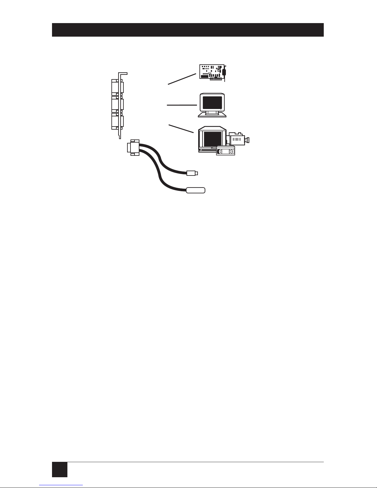
External VGA Connection
Take the supplied VGA interface
cable and plug it from your VGA
card into the VGA In port of the PC
IMAGE II. The 6-pin circular end
plugs into the PC Image II, and the
15-pin male end plugs into your PC’s
VGA port.
Use the cables supplied with the PC
IMAGE II when connecting external
devices. This is especially important
when hooking up the VGA Card.
Plug in the VGA Monitor
Plug your VGA monitor into the
VGA Out port (the middle port)
on the PC IMAGE II.
Video Output Device
Plug your external video device into
the PC IMAGE II.
Plug the 9-pin video cable into the
bottom port of the PC IMAGE II
card. This cable has both the 4-pin
S-Video connections and the RCA
®
plug for composite video.
Plug your video device into the
appropriate Video Out port on the
PC IMAGE II’s video cable.
Use the S-Video connection
whenever possible to ensure the
highest-quality video signal.
VGA In
VGA Out
Video Out
Plug
S-Video Out
Composite Video Out
Figure 2-2. Connecting the PC Speaker.
Page 12
11
CHAPTER 2: Quick Install
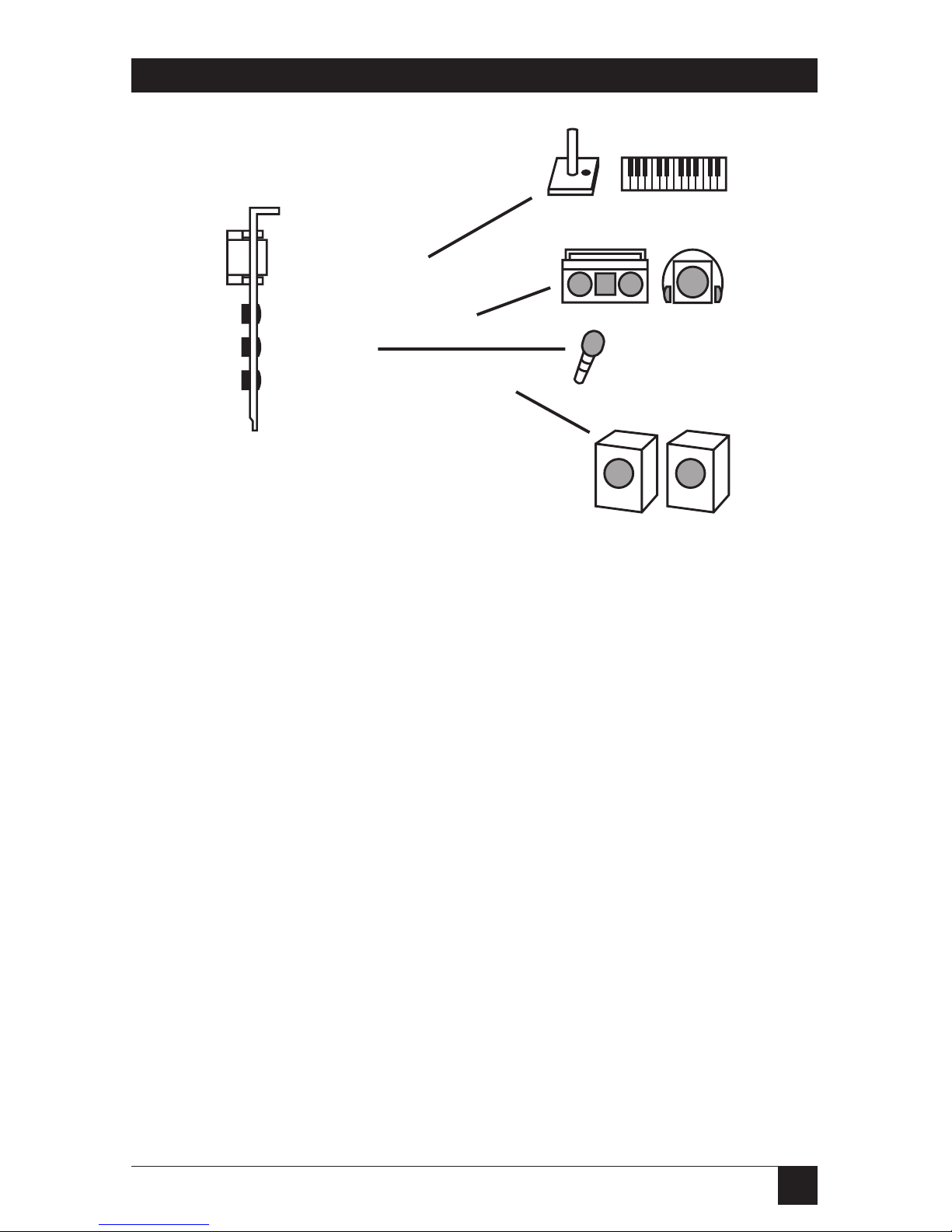
Speakers
The speakers plug into the Audio
Out port of the audio header cover.
See Figure 2-2 for proper
connections.
Plug in all cables (speaker, joystick,
audio in, mic, etc.) before powering
up your PC.
Joystick
Plug the joystick into the 15-pin
joystick on the top of the header
cover.
External Audio Input
You can connect an external audio
source (tape player, radio, etc.) to
the PC IMAGE II. Use the
appropriate converter cable to
interface to your external
equipment.
Joystick/MIDI
Audio Input (stereo)
Mic Input
Audio Output (speakers)
Figure 2-3. Connecting the Video Output Device.
Page 13

12
PC IMAGE II
Microphone
You can connect a 300-600 ohm
microphone to the PC IMAGE II.
Plug it into the middle 1/8-inch
mini plug on the audio header
cover.
Power up the PC
You can now power up the PC. If the
installation is correct, you should see
text appear on your VGA monitor. If
you don’t, either go through the full
installation instructions in Chapter
3, or refer to Chapter 8,
Troubleshooting.
The video display (televsion or VCR)
of PC IMAGE II is set for 640 x 480
graphics resolution. This means
that under Windows or graphic
applications, no software driver is
necessary. In order to see text
screens on the TV set; you will have
to load the PC2NTSC driver. See
Chapter 4.
Run the INSTALL Program
Place your PC IMAGE II install
diskette in your disk drive and type
INSTALL.
The program will prompt you for
input, and will test and setup your
PC IMAGE II.
Run the Windows Install Program
To run the Windows Install
program:
Start Windows 3.1 (type WIN).
Select the File menu from the
Program Manager, select the “Run”
option, and then type X:INSTALL.
The PC IMAGE II System should be
ready to go. Skip the next two
chapters and go on to Chapter 5.
Page 14
13
CHAPTER 3: Hardware Installation
You can install the PC IMAGE II
card in any full-length slot of an
IBM AT, 80286, 80386, 80486, or
compatible with an ISA (Industry
Standard Architecture (ISA) bus.
The steps described on the following
pages illustrate the procedures for a
typical system. Your system may
differ slightly.
NOTE
Steps 6 through 8 protect
your PC IMAGE II card from
accidental damage from
static electricity. These
procedures apply to all cards
that contain CMOS or other
components that are
sensitive to static elecricity.
Do not remove your PC
IMAGE II card from its
protective sleeve until
advised to do so.
3.1 Hardware
1.Turn off your PC, but leave the
power cable connected to the
wall outlet to ensure that your
PC is grounded.
2.Remove the screws from the back
of the PC cover. Be sure to use
the proper size screwdriver or
you will strip the heads.
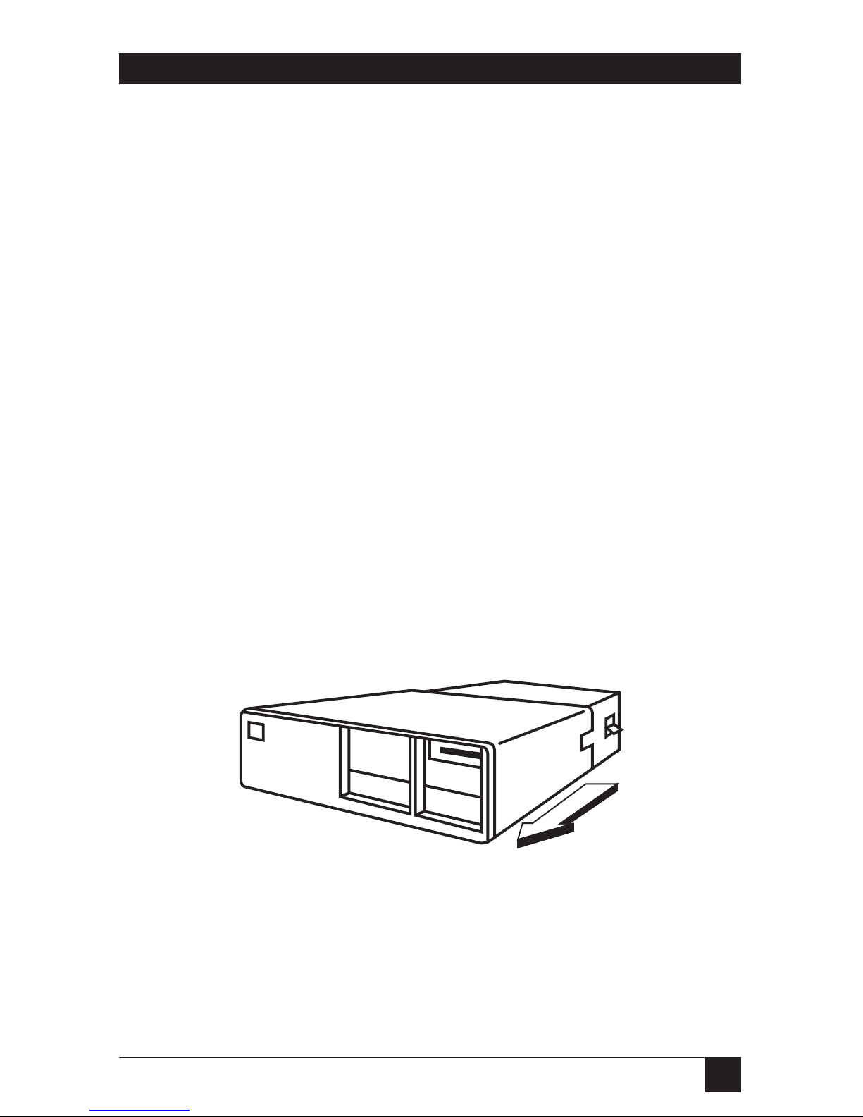
3.Use both hands to pull the cover
forward and slowly remove it
from the system unit (see Figure
3-1). Be careful. Sometimes
there is a bracket that gets
caught on the cables inside
the PC case.
3. Hardware Installation
Figure 3-1. Removing the PC Cover.
Page 15
14
PC IMAGE IIPC IMAGE II
4.Locate an unused slot. Any full-
length slot can be used.
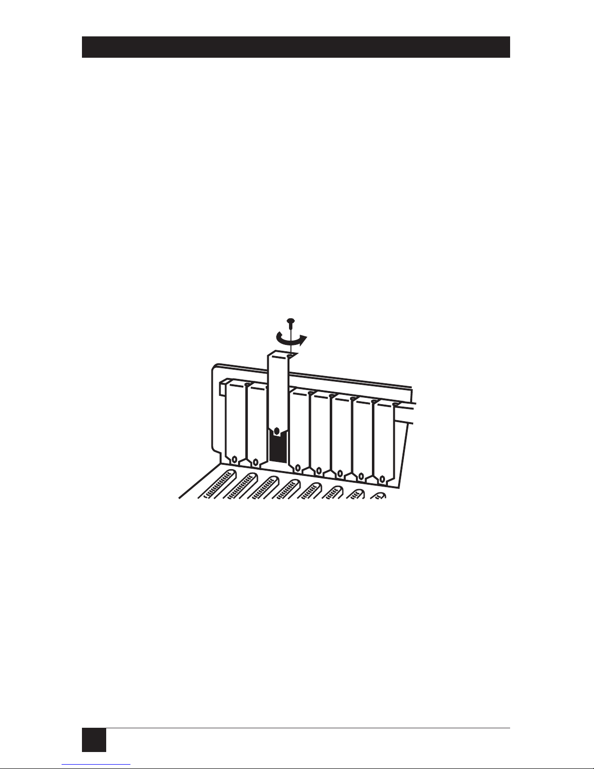
5.Remove the slot cover (see
Figure 3-2). Save the screw to
anchor the PC IMAGE II’s
mounting bracket later.
6.Pick up the card (still in the
sleeve) by grasping the edge
bracket with one hand. Avoid
pressing on the card
components. With the other
hand, touch an unpainted metal
surface, such as the rear panel of
the PC, to discharge any built-up
static electricity in your body.
7.Remove the plastic sleeve with
your free hand.
8.Touch and unpainted metal
surface a second time to ensure
there is no static build-up.
Figure 3-2. Removing the Slot Cover.
Page 16
15
CHAPTER 3: Hardware Installation
3.1.1 S
ET THE
CD-ROM J
UMPERS
Your PC IMAGE board includes a
CD-ROM interface. If you wish to
connect a CD-ROM drive, you will
have to set two jumpers. If you are
not using the CD-ROM interface, go
to the next section.
Jumpers 15 and 16 set the IRQ level
and DMA channel for the PC
IMAGE II’s CD-ROM interface. Set
these so that they do not conflict
with other peripherals in your PC.
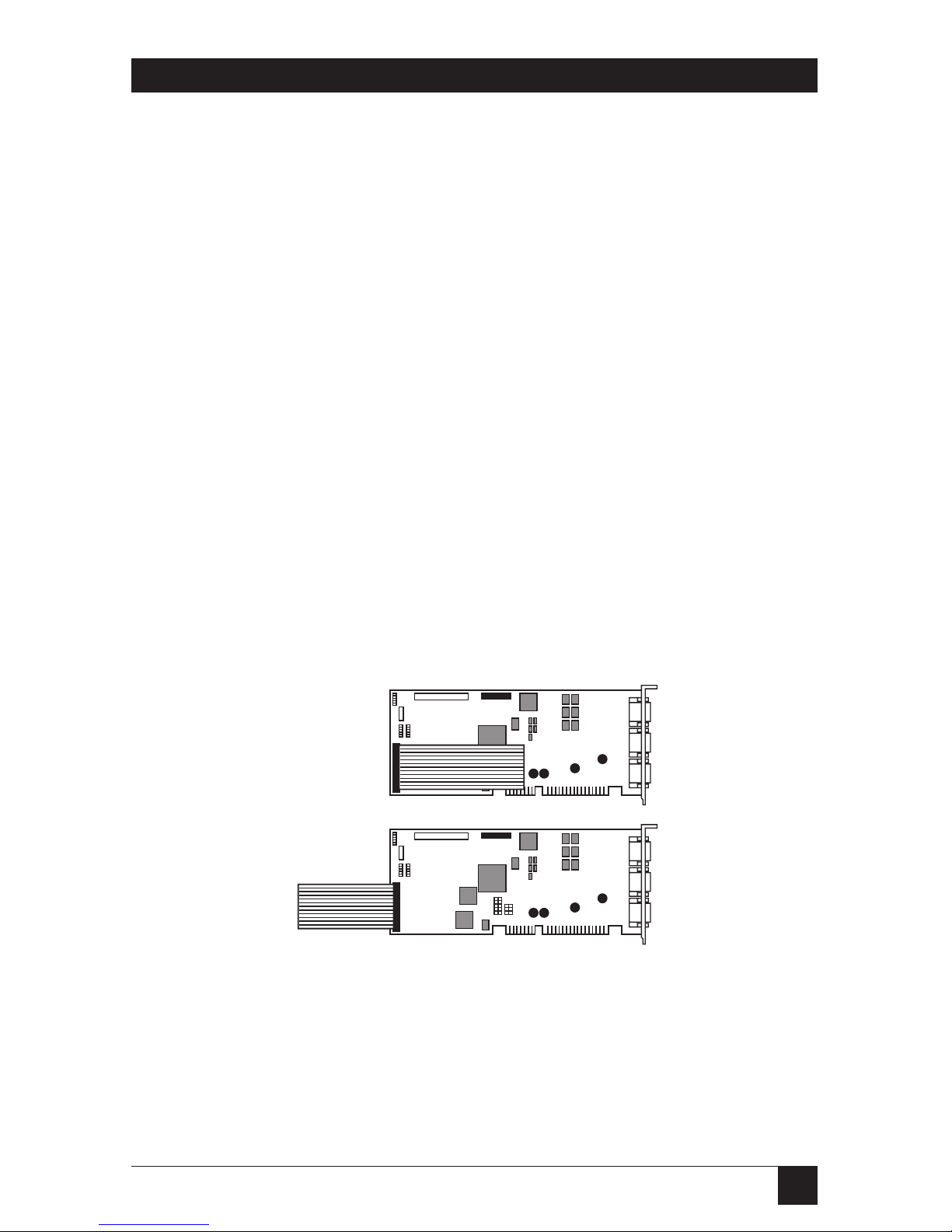
3.1.2 C
ONNECT THEAUDIOHEADER
The audio header is a long, flat
ribbon cable with an expansion slot
connector at one end. Plug this
cable into the back of the PC IMAGE
II board (see Figure 3-3). Plug the
connector into the board so that the
cable can be routed towards the
back of the PC without any loops or
turns. This will ensure that Pin 1 on
the cable lines up to Pin 1 on the
board.
Pin 1 on the PC IMAGE II board is
marked with a small triangle. Pin 1
on the cable is marked with a red
stripe or small triangle, or both..
Correct
Incorrect
Figure 3-3. Connecting the Audio Header Cable.
Page 17
16
PC IMAGE IIPC IMAGE II
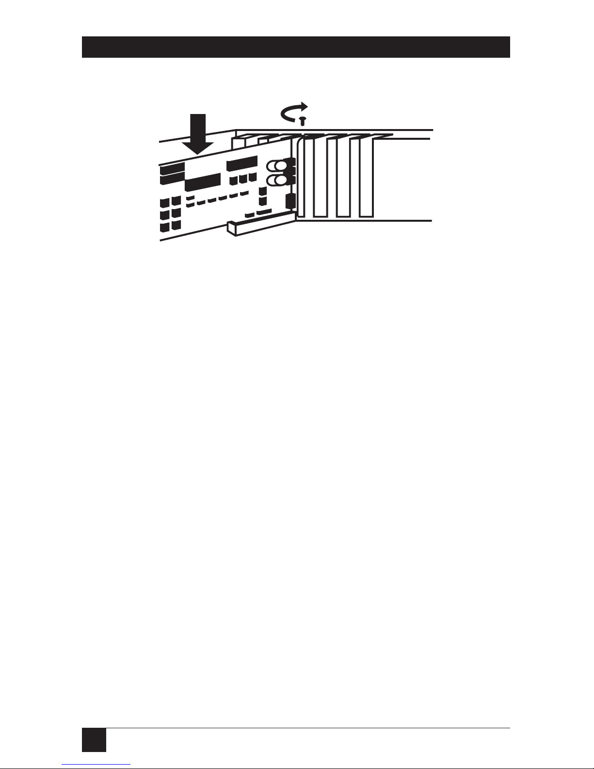
Insert the card into the expansion
slot. Press firmly to ensure that the
card is fully seated. Anchor the
card’s mounting bracket using the
screw from the earlier steps.
3.1.3 I
NSTALL THEAUDIO-HEADER
C
OVER
Remove one of the slot covers from
the back of your PC. Route the
audio-header cable to the back of
the computer and install it in the
expansion-slot opening.
3.2 Attach PC Speaker Wires
(Optional)
To reroute the PC speaker cable to
the PC Image II, locate the 2-wire
cable that runs from your PC
motherboard to the speaker inside
your PC. Grasp the plug at the end
of the wires, where it connects to the
motherboard, and pull gently.
Attach this plug to the 4-pin PC
speaker connector near the rear
corner of your PC Image II. The
connector is close to the CD-ROM
connector. You don’t have to worry
about the orientation of the plug,
since the sound is identical either
way.
After rerouting the cable, you will
still hear the customary beeps, key
clicks, and other familiar PC speaker
sounds even when your PC Image II
is not in use. An added bonus is that
you can now control the volume of
all sounds coming out of your
speaker.
Some connectors are non-standard
and may not plug onto your PC
Image II card. Look in Appendix A
for connector pin definitions and
further information.
Figure 3-4. Inserting the PC Image II into the PC Slot.
Page 18

17
CHAPTER 3: Hardware Installation
3.3 Connecting SCSI CD-ROM Drives
Each CD-ROM drive manufacturer
uses a different type of audio-cable
connector. If the cable included with
our kit will not connect to your PC
Image II, call Black Box.
3.3.1 CD-ROM D
RIVESETTINGS
Your CD-ROM drive’s ID numbers
are configured at the factory with
default settings. Refer to your
CD-ROM drive’s documentation
for altering the settings, or for
troubleshooting information.
Before you start, the CD-ROM drive
must be properly installed and
connected to your power supply
within your PC’s case. Refer to your
CD-ROM drive’s manual for these
steps. Follow the descriptions below
for connecting your CD-ROM drive
to your sound card. If necessary,
refer to the illustration for
connector locations.
In order to connect the Data Cable
and Audio Connector to the PC
Image II, you may have to temporarily remove any card to the
immediate right of your bracket
adapter.
3.3.2 C
ONNECTING THEDATACABLE
Connect one end of the 50-pin SCSI
(ribbon-type) cable to your PC
Image II’s CD-ROM connector. Pin 1
on this connector is on the upper
right corner of the connector. Make
sure that Pin 1 on your SCSI cable
(red stripe) is connected to this pin.
Connect the other end of the SCSI
cable to your CD-ROM drive.
3.3.3 C
ONNECTING THEAUDIOCABLE
Attach one of the 5-pin connectors
on the Internal Audio connector
cable to the PC Image II’s
connector. The audio cable and this
connector are keyed so that the
cable will plug in only one way.
Connect the other end of the audio
cable to the CD-ROM drive’s audio
connector. When all of these steps
are complete, your CD-ROM drive
should be connected to your PC’s
power supply and to your PC Image
II through the data cable and audio
cable.
Do not plug the CD-Audio
connector into the PC-speaker jack.
You don’t need to change the SCSI
ID on your CD-ROM drive unless
you connect additional SCSI devices
to your PC Image II. If you want to
connect other devices in addition to
your CD-ROM drive, refer to your
CD-ROM drive’s documentation for
SCSI ID settings.
Page 19

18
PC IMAGE IIPC IMAGE II
3.3.4 R
EASSEMBLE THE
PC
Put the cover back on your PC and
secure it.
3.4 Connecting to a Television
Monitor
There are three ways to connect
your PC IMAGE II to video
equipment. Please follow the
directions under the appropriate
heading.
3.4.1 RCA P
LUG(VIDEOOUT
)
Plug the RCA plug from the PC
IMAGE II’s Video Out cable into
the television’s Video Out plug.
3.4.2 4-PINDIN
PLUG
(S-V
IDEO
)
The S-Video connection separates
the luminance and chrominance
video signals, providing the highest
image quality. The S-Video
connector is a circular plug on your
television set with 4 pins. Use the
cable provided in the PC IMAGE II
package to connect to this port.
3.4.3 C
ABLEINPUT(ANTENNAINPUT
)
The antenna hookup on your
television set may be used with PC
IMAGE II. This hookup, however,
decodes the video signal from RF
waves. This requires that you convert
the video signal from the PC IMAGE
II radio-frequency waves through the
use of an RF modulator. This
optional accessory is available at
local electronics stores.
Do not use the “GAME” RF
modulators. These units encode
both audio and video.
3.5 Protecting Your Sound Equipment
If you have attached the PC’s
internal speaker to the PC IMAGE
II, keep the speaker volume low,
since the speaker cannot tolerate
excessive power for a sustained
period.
Never plug Line Out or the speaker
connector of your PC IMAGE II, or
any other audio equipment, to the
output of another audio device. This
may damage your equipment.
Page 20

19
CHAPTER 4: Software Installation
4.1 Installing DOS Drivers and
Software
The DOS Installation disk of the PC
IMAGE II set contains a file called
INSTALL.EXE, which performs the
following tasks:
• Creates the PCIMAGE
subdirectory.
• Configures the various IRQ,
DMA, and I/O settings, as well as
enabling or disabling emulation
modes and a joystick.
• Copies files onto your hard disk
from the floppies.
• Adds the MVSOUND.SYS sounddevice driver and the CD-ROM
driver to the CONFIG.SYS file.
• Optionally adds MSCDEX.EXE
to the AUTOEXEC.BAT file.
• Copies the PC2NTSC program
to the hard disk. This program
drives the TV output for DOS
applications.
Before proceeding, be sure to make
backup copies of the original disks.
Use the DOS DISKCOPY command
to back up your diskettes. See your
DOS manual for information.
4.2 Installation Procedures
Make sure speakers or headphones
are plugged into the sound card's
line out jack, so you can hear when
the test file plays.
When typing commands, press the
enter key when you see the [Enter]
command. Use the appropriate drive
(A: or B:) for the type of disk you are
using (3.5" or 5.25").
Place your program disk #1 in floppy
drive A: or B:, and type:
A: (or B:) [Enter]
INSTALL [Enter]
The first screen that appears lets you
“Install Software and Setup
Hardware” or just “Setup Hardware
Only.” Use the arrow keys to
highlight “Install Software and Setup
Hardware.” Press [Enter].
The second screen describes the
installation program and asks if you
want to use the default directory
(C:\PCIMAGE). If not, press the
backspace key to erase the name,
and type in the name of the
directory you want to use. Then
press [Enter].
4. Software Installation
Page 21

20
PC IMAGE II
The third screen is the configuration
screen. It shows the default DMA,
IRQ, and I/O settings for the PC
Image, Sound Blaster™, and MPU401 emulation modes.
If you’re resetting the hardware, this
screen shows the current settings.
This screen also lets you enable or
disable the emulation modes, and
the joystick. You can select “Yes” at
the appropriate option to have the
program automatically modify your
PC’s AUTOEXEC.BAT and
CONFIG.SYS files. You must modify
the CONFIG.SYS file for the sound
card to work.
Use the arrow keys to highlight a
category to change. Press [Enter] to
choose other options for that
selection.
When you have made all of your
selections, highlight “Accept the
configuration shown above,” and
press [Enter].
NOTE
The Sound Blaster
compatibility mode and the
PC Image mode must use
different IRQ and DMA
settings.
Now the program presents a test
screen. If you current settings are
correct, a sound file is played back.
The sound momentarily plays and
stops, signifying that your settings
are correct. If the test is successful,
press [Enter].
If the sound file “skips” and does not
stop, your IRQ settings are conflicting. Press [Esc] to return to the
configurations screen and select a
new IRQ.
NOTE
If there is a DMA conflict,
you may hear a loud hissing
sound, or it may totally
inhibit your PC Image’s
ability to play back digital
sound files. Choose a
different DMA channel.
If there is an IRQ conflict, the
sound file keeps playing like
a skipping record. Choose a
different IRQ channel.
The next test screen checks the
Sound Blaster emulation settngs. A
sound file plays that signifies correct
or incorrect settings. If the settings
are incorrect, press [Esc] and the
program returns to the
configuration screen. If the settings
are correct, press [Enter].
Only when both tests have been
successfully completed can the
program copy all of the necessary
files to your chosen directory and
modify the AUTOEXEC.BAT and
CONFIG.SYS files.
When the installation is complete,
press [F3] to exit. Press [F3] to exit.
Reboot your system to return to the
DOS prompt, after which you can
start using PC Image.
You can change your original DMA
and IRQ settings, and disable or
enable your joystick, at any time.
Simply re-run the install program
from your PCIMAGE directory and
make the necessary changes.
You must reboot your PC for the
change in the AUTOEXEC.BAT and
CONFIG.SYS files to take effect.
Page 22

21
CHAPTER 4: Software Installation
4.3 CD-ROM Driver Setup
This section describes the CD-ROM
drivers included with the PC Image
II. These drivers are the
TSLCDR.SYS drivers and the
MSCDEX.EXE driver for Windows.
4.3.1 U
SINGYOUR
SCSI D
RIVER
The TSLCDR.SYS provides a
software interface for SCSI (50-pin)
hardware to the MSCDEX.EXE
driver. This driver is automatically
added to the CONFIG.SYS file by the
installation program.
The entry in the CONFIG.SYS file
should look like the example below:
device=[path]\tslcdr.sys
/d:mvcd001/p:3
Where:
•`[path] specifies the DOS path to
tslcdr.sys.
• /d:mvcd001 specifies the device
name.
• /p:3 enables CD-ROM seek
commands.
4.3.2 O
PTIONALPARAMETER
/r resets the SCSI devices.
4.4 The MSCDEX Driver
MSXDEX.EXE provides a Windows
software interface to all applications
that address the CD-ROM drive.
MSCDEX.EXE is automatically
installed in your AUTOEXEC.BAT
file by the installation program.
This file is required in order for your
CD-ROM drive to be recognized by
Microsoft Windows.
The entry in the AUTOEXEC.BAT
file should look like this:
[path]\mscdex.exe/d:mvcd001
/m:10/v
Where:
• [path] specifies the DOS path to
MSCDEX.EXE
• /d:mvcd001 specifies the device
name.
• /m:10 specifies the buffer
memory allocation.
• /v causes the MSCDEX.EXE to
display a verbose listing of
information about memory
usage.
4.4.1 O
PTIONALPARAMETERS
• /l:[drive letter] lets you specify
the DOS drive letter of the
CD-ROM drive.
• /e instructs MSCDEX to use
EMS memory.
Page 23

22
PC IMAGE II
4.5 MVSOUND.SYS Driver
The file MVSOUND.SYS is the
device driver for the PC Image which
is automatically loaded when your
PC boots. It initializes the card and
provides access to the on-board
mixer and volume control and must
be correctly installed in your PC’s
CONFIG.SYS file.
If you choose to edit this line in the
CONFIG.SYS manually, it must
conform to the following syntax.
DEVICE=C:\PATH
\MVSOUND.SYS
D:#Q:#/J:#/S:#/M:#
Example:
\MVSOUND.SYS D:3
Q:7/J:1/S:1,220,1,5/M:1,330,2
Each switch (letter) in the statement
above should be followed by a
value(s). Values are separated by
commas. Follows are examples of
how to set each switch. Default
settings are marked with an asterisk
(*).
D:=DMA Channel 0, 1, 3*, 5, 6, 7
Q:=IRQ Channel 2, 3, 5, 7*, 10, 11,
12, 15
Joystick 1=On*, 0=Off
/S:
IRQ Channel 2, 3, 5*, 7
DMA Channel 0, 1*, 3
I/O Address 220*, 230, 240
SB Emulation 1=On*, 0=Off
/M:
IRQ Channel 2, 3, 5*, 7
I/O Address 300, 330*
MP-401 Emulation 1=On*,
0=Off
Some PCs have a defective “OSC”
(oscillator) signal. The FM
synthesizer and PC speaker
emulation are sensitive to the signal.
The symptom appears as static noise
when the volume of the FM on the
mixer is set to full. This defect may
be compensated for by adding the
/T:1 switch to the end of your
MVSOUND.SYS device statement
to reduce the noise levels in your
recordings.
For example, the /T:1 switch selects
the 28.224 MHz frequency oscillator
(divided by 2) instead of the system
oscillator clock of 14.31818 MHz
frequency.
Remember that changes to
CONFIG.SYS do not take effect
until you reboot the PC.
Page 24

23
CHAPTER 4: Software Installation
4.6 Changing the Volume Level
Once MVSOUND.SYS is installed
in your PC, you can change the PC
IMAGE volume while running your
DOS or Windows applications:
• [Ctrl] + [Alt] + [U] — Increases
volume
• [Ctrl] + [Alt] + [D] — decreases
volume
• [Ctrl] + [Alt] + [M] — toggles
mute.
4.7 Changing Hardware Settings
With A Text Editor
If you did not allow the installation
procedure to change your
CONFIG.SYS automatically, you
should insert the line yourself. Do
this only if you are familiar with
editing DOS text files.
4.8 Installing the DOS Video Driver
When your PC Image first boots up,
it is set to run in 640 x 480 graphics
mode. Your memory intensive
graphics applications will run
without requiring a software driver.
For DOS and text applications to
appear on the television screen
properly, the file PC2NTSC.COM
must be loaded. Change to the
PCIMAGE directory and type:
PC2NTSC.
A screen appears providing various
options for positioning the screen
and for changing the flickerreduction modes.
4.8.1 F
LICKERREDUCTION
Press the Ctrl, Alt, and F keys
simultaneously to toggle between
the various PC Image display modes.
Each mode will change the amount
of flicker that appears on the screen.
Select the mode that provides the
most stable display for your
television or VCR.
4.8.2 S
CREENPOSITION
Use Ctrl, Alt, and the arrow keys to
center and adjust the display
position.
On some televisions and VCRs, the
top or bottom of the image may not
be visible. Because of the limitations
of the television signal, there are no
adjustments on the PC Image to
adjust the size of the televsion image.
Either resize your presentation/PC
application or adjust the controls on
your television set.
4.9 Installing Windows Drivers
To install Windows drivers, you must
have successfully installed Windows
3.1 or Windows with Multimedia
Extensions 1.0a on your PC. If you
are updating your drivers, be sure to
delete your old drivers first. Use the
“Drivers Applet” in Windows’ control
panel (the control panel is located
in Windows Main program group).
Earlier versions of Windows do not
support audio.
Insert your Windows Utilities
diskette into drive A: or B:. Start
Windows by typing WIN.
Page 25

24
PC IMAGE II
From the Windows File menu, select
the “Run” option and type:
X:\SETUP.EXE, where X is the drive
where the PC Image diskette is
located.
The install program automatically
locates your Windows directory and
asks you to confirm the current
Windows path. Click on the “OK”
button or correct the path and then
click “OK” to proceed.
At this point, the install program is
ready to modify your SYSTEM.INI
and WIN.INI files, and asks you if
you want to be prompted for each
driver setting. Click on the “yes”
button. At every subsequent prompt,
click on the “yes” button, unless one
of the default settings conflicts with
other hardware or software you have
installed..
Once the installation is almost
complete, the installation program
asks if you want to reboot. Select the
“yes” button. You must reboot
Windows in order for your new
drivers to become active.
Upon entering Windows, an
introductory sound file is played. If
this sound file plays continuously,
you have an IRQ conflict.
4.9.1 I
NSTALLING
MCI CD-A
UDIO
D
RIVERS
You must have your CD-ROM drive
and device driver installed before
beginning these steps. Since
Windows 3.1 does not automatically
install the CD -Audio drivers, you will
want to install the drivers before you
run any MPC applications that use
CD-Audio.
From the Program Manager, select
the Window menu and choose
“Main”.
Double-click on the Control Panel
Icon. Double Click on the Drivers
icon.
Once the drivers selection box
appears, click on the Add button.
When the Add selection box
appears, click on the (MCI) CD
Audio Selection. Click on the OK
button to proceed to the next stage.
Next, Windows prompts you to
place the disk with the updated
MCICDA.DRV driver in your
selected disk drive. Place the correct
disk in your drive and click on the
OK button.
Windows will install the driver and
verify that a CD-ROM drive exists.
Windows will return a mesage that
says “One CD-ROM drive was
detected. Installation is complete.”
Click on the Close button to return
to the Control Panel.
Page 26

25
CHAPTER 4: Software Installation
4.9.2 C
HANGING THEHARDWARE
S
ETTINGS FORWINDOWS
When you enter the Windows 3.1
environment, the PC IMAGE settings
in the Windows control panel take
precedence over the DOS settings.
When you exit Windows 3.1, the
DOS settings become active again.
The DOS and Windows settings can
be set to the same values. Follow
these steps to configure Windows 3.1
with different DMA and IRQ
settings:
1.From the Program Manager,
select the Windows menu and
choose the Main selection.
2.Double-click on the Control
Panel Icon.
3.When the Control Panel group
appears, double-click on the
Drivers icon.
4.Highlight the
“PCIMAGE/Spectrum
WAVE/MIDI/AUX” driver in
the Installed Drivers selection
window. Click on the “Setup...”
button.
5.The PC Image Setup dialog box
appears with the current DMA
and IRQ settings. Any numbers
grayed out are not available.
6.Point and click on the circle
which corresponds to your new
DMA and IRQ settings. Click on
the OK button.
You must exit Windows for your new
drivers to become active.
4.9.3 R
ESOLVING
DMA
AND
IRQ
C
ONFLICTS IN
DOS
An IRQ problem will interfere with
your PC IMAGE’s ability to play both
MIDI music and digital audio. If you
discover an IRQ or DMA conflict
between the PC Image and another
card, use the following steps to
reconfigure PC Image.
1.Determine which IRQ line and
DMA channel you want to use.
2.Run the PC IMAGE install
program to select your IRQ and
DMA settings. If your settings are
correct, a sound file is played
back from your PC. If the sound
file skips, you have an IRQ
conflict. Use the Install program
to choose each IRQ until you
find a channel that doesn’t
conflict (the sound file plays
correctly).
If a conflict still exists, try another
IRQ or DMA setting by repeating
this process.
Reboot the PC to activate the revised
CONFIG.SYS file.
4.9.4 U
NDERSTANDING
IRQ
S
Your PC IMAGE uses an interrupt to
communicate with your PC system.
When the PC IMAGE needs your
PC’s attention, it issues an interrupt
to gain the attention of your PC’s
CPU.
Page 27

26
PC IMAGE II
The Install program lets you select
the interrupt request level for PC
Image’s audio circuitry.
You must choose an interrupt level
that no other device in your PC is
using.
Most DOS programs can only
recognize DMA 1 and 3 and IRQ 2,
3, 5, and 7.
There are several possible conflicts.
IRQ assignments vary, but the typical
IRQ assignments listed below are the
most common. Check network cards,
Fax/Modem cards, SCSI adapters
and tape backup units for already
used IRQs and DMAs. The default
IRQ for the Sound Blaster part and
the PC Image portion of the card is
5.
Typical IRQ assignments:
• IRQ 2 — Interrupt 8-15
• IRQ 3 — COM2
• IRQ 4 — COM1
• IRQ 5 — LPT2: (2nd printer)
• IRQ 6 — Floppy disk controller
• IRQ 7 — LPT1: Printer
• IRQ 10 — Not Available
• IRQ 11 — Novell Disk
• IRQ 12 — Not Available
• IRQ 13 — Math co-processor
• IRQ 14 — Hard disk
4.9.5 U
NDERSTANDNG
DMA C
HANNELS
Your PC has six usable DMA
channels for rapid data transfer
between peripherals (including your
hard drive) and memory. The PC
Image typically uses one DMA
channel for high-speed transfer of
waveform (PCM digitized audio)
sound data. Wave form files are used
to add special effects, such as sounds
or a voiceover, to the background
melody.
The Install program included with
your PC Image lets you select the
DMA channel through the software.
There are no jumpers to set. You can
set the PC Image to DMA channels 1
and 3. DMA channel 1 is used for
the Sound Blaster Compatibility
mode.
Ideally, your PC Image will not have
to share a DMA channel with
another device in your PC. However,
if you run out of DMA channels, you
can share, but you must not use the
PC Image (in particular the PCM
feature for digitized audio) and the
other device simultaneously. For
instance, you can share DMAs with
the Sound Blaster compatible part of
your board. You must not share a
DMA channel with a hard drive or a
network card since one or both of
these would be active while you
operate your PC IMAGE.
Page 28

27
CHAPTER 4: Software Installation
Typical DMA assignments are listed
below. DMA 3 is the DMA channel
most likely to be available.
• DMA 1 — Available
• DMA 2 — Floppy Disk
• DMA 3 — Available
• DMA 4 — Memory Refresh
• DMA 5 — Unassigned
• DMA 6 — Unassigned (not
recommended)
Note that all of the devices listed
below require a DMA channel and
may already use DMA channels 3, 4,
5, 7, and 0:
• Network Card
• Tape-Backup Unit Controller
• Proprietary Printer Card (such
as a PostScript®controller)
• SCSI or Other Storage Device
Controller
• Scanner Card
• SDLC Controller
4.9.6 C
ONFLICTSWITHOTHER
P
ROGRAMS
Simplify your CONFIG.SYS so it
includes only the FILES, BUFFERS,
and the DEVICE= command for the
MVSOUND.SYS. You must also
retain in your CONFIG.SYS any
absolutely essential device drivers,
such as DMDRVR.BIN, which is
necessary for some types of disk
drives. To maintain a standard,
configure FILES to 20 and BUFFERS
to 24.
Before revising your CONFIG.SYS
and AUTOEXEC.BAT, you should
make copies of them. Ideally, you
should create a working floppy boot
disk with your current CONFIG.SYS
and AUTOEXEC.BAT before
experimenting with these files on
your hard disk. Check your DOS
manual on how to create a boot disk.
You should simplify your
AUTOEXEC.BAT. Remove
everything but your PROMPT and
PATH statement. Also remove any
TSR programs, disk caches, RAM
disks, menu, or shell programs.
Page 29

28
PC IMAGE II
5.1 Introduction to PAS
The PCIMAGE subdirectory contains
a utility program called PAS.EXE.
This utility lets you control the
mixer, equalizer, and volume
controls of your sound card by using
an on-screen mixer control panel.
Figure 5-1 shows how the mixer ties
together many different audio
sources.
You can also use PAS by typing
commands from the DOS command
line or sending them from a batch
file. Note that for convenience, we
sometimes say “mixer” when we
actually mean the mixer, equalizer,
volume control, and related devices
that you can control on your sound
card.
Settings you enter with the PAS
utility will be lost if you run an
application program that requires
VMP to be loaded.
5. PAS Utility
Figure 5-1. Using the Mixer to Connect Various Audio Sources.
Page 30

29
CHAPTER 5: PAS Utility
5.2 Mixer Control Panel
To display the on-screen mixer
control panel, you must first switch
to the PCIMAGE directory if you
haven’t included this in your PATH:
C:\CD PCIMAGE [Enter]
PAS * [Enter]
You must type a space between
“PAS” and the asterisk and press the
[Enter] key to initiate the PAS mixer
(from within the PCIMAGE
directory).
The following keys have special
meanings when using the interactive
mixer:
• [F1] — Displays on-line help
• [F2] — Accesses control panel
for recording special effects
• [F4] — Restores default settings
• [Tab] — Advances to the next
control down (or to the right)
• [Shift Tab] — Advances to the
next control up (or to the left)
• [Enter] — Toggle this option on
or off
• [Esc] — Quit the control panel
(your changes to the settings are
saved automatically)
Press [F1] to see the help screen,
which lists the keys available for
navigating within the mixer panel
and for moving the slide controls.
The Mixer and Volume Control slide
controls initially appear as a solid
bar that extends across both left and
right channels. Actually, the left and
right channels can be adjusted
independently or together,
depending on which key you use.
When the name of a slide control is
highlighted, you will adjust that
control when you press the cursor
keys (such as [PgUp] or [Right])
or press the [Enter] key.
The cursor keys move the slide
control while the [Enter] key toggles
this source as a potential input for
waveform (PCM digital audio)
recording. When a slide control is
selected for recording, the words
“Play & Record” appear to the right
of it. When the control is selected
for just playback, the screen shows
“Play Only.” You may still need to
adjust the volume. Input volume is
controlled by using the [Right] or
[Left] arrow keys to move the slider
to the left or right. Note how the
slide is all the way to the left where
the dots are the smallest. This is the
minimum setting, which is
equivalent to off. The dots indicate
the direction for increasing a setting;
slide the control toward the larger
dots to increase the effect.
The on/off buttons, such as
Loudness and Enhanced stereo, are
toggled on/off by pressing the
[Enter] key while that control is
highlighted.
Page 31

30
PC IMAGE II
The master Volume Control, visible
on the right side of the Main
Control Panel, controls the volume
you hear through your headphones
or speaker. This includes all sound
sources whether or not they are set
for recording input.
There are several special effects
available which appear when you
press [F2]:
• Recording Monitor Level — The
default setting, a middle setting,
is appropriate for most
recording sessions. This controls
the volume, heard through the
speakers or headphones, of all
inputs selected for recording. It
has no effect upon the recording
volume or the volume of inputs
not selected for recording.
• Channel Connections — For
normal stereo recording, you
will want to use the default leftto-left and right-to-right channel
connections. You can force monaural output by mapping left-toleft and left-to-right, or right-toleft and right-to-right.
• Real Sound Support — Turn on
real sound if your game software
supports it. Enabling this options
changes the sound of your PC
beeps.
The sound card is capable of very
sophisticated control over mixing.
All sources can be controlled
individually. All inputs selected
for recording are combined into
a single input that can be mixed
with the non-recorded inputs. In
addition, when you adjust the
volume for listening comfort, you
do not affect the volume at which
recording takes place.
If you wish to hear only inputs
selected for recording, turn down
the individual volume level for all
other inputs, set the Recording
Monitor Level to an intermediate
setting, and adjust the master
Volume Control. If you wish to
hear only inputs not selected for
recording, turn down the setting of
the Recording Monitor Level (or
turn down the individual recording
inputs) and then adjust the Master
Volume Control. If you wish to hear
both recording and non-recording
inputs, adjust the Recording
Monitor Level and the individual
non-recording inputs so you hae the
correct balance. Adjust the master
Volume Control to a comfortable
level.
Both the Recording Monitor Level
and the Master Volume Control
affect only what you hear; they do
not change the volume at which a
source is recorded. The volume level
for digital audio recording is set by
the individual slide controls for the
inputs selected for recording.
Page 32

31
CHAPTER 5: PAS Utility
As an example of this sophisticated
mixing control, suppose you are
singing along with an internal CD
player but wish to record only your
voice. You would select for recording
only the microphone input and
adjust its slide control, adjust the
Internal Connector slide to make for
a good balance between the two, and
then adjust the master Volume
Control for comfortable listening.
5.3 Command Line Mixer Control
This section explains how to use PAS
Utility command lines to access each
of the functions. This is an
alternative to the on-screen mixer
control panel for customizing how
your sound card operates. The PAS
utility recognizes a select set of
English keywords, entered either at
the DOS command line or issued by
a batch file. The PAS command
language includes commands and
effects which are not available
through the on-screen mixer control
panel.
This section is of interest primarily
to people who have very
sophisticated requirements. If you
find the on-screen mixer control
panel—accessed from either
AudioLink or from the DOS
command line—adequate for your
purposes, you can skip this section.
5.3.1 PAS K
EYWORDS
There are six sources of audio that
can be combined in the mixer. Each
source is identified with a keyword:
• FM — Stereo FM synthesizer
• PCM — Digitally sampled audio
(PCM) playback
• INT — Internal CD-Audio
connection
• EXT — External Stereo jack
• SPEAKER — PC speaker
• MIC — Microphone jack
Each audio source has a left channel
and a right channel assoicated with
it; therefore, to refer to the FM
synthesizer on the right channel,
the keywords FM RIGHT are used
together. If FM appears without
LEFT or RIGHT, it is assumed that
the action is to take place on both
channels.
Additional keywords used to build a
command sentence are listed below:
• SET — Start of command line
for setting a fixed value
• FADE — Start of command line
for a gradual change
• TURN — Start of command line
for toggling a setting on
• VOLUME — Overall output
volume
• INPUT MIXER — Source to the
mixer should be in record mode
Page 33

32
PC IMAGE II
• OUTPUT MIXER — Source to
the mixer should be in the play
mode
• FROM — Starting point for a
fade-in or fade-out
• TO — Stopping point for a fade-
in or fade-out
• TREBLE — Specifies treble
adjustment
• BASS — Specifies bass
adjustment
• ENHANCED — Turns treble
and bass enhancements on or off
• MUTE — Turns ouput audio on
or off
• ON — Turns specified feature
on
• OFF — Turns specified feature
off
• SECONDS — Specifies the
period in seconds of a fade
The last set of keywords are special
cases in that they can be used on a
command line alone. The keywords
that fall into this category are
described below:
• HOLD — Instructs PAS to place
the following commands (up to
16) in a queue to be executed
when a RELEASE command is
received.
• RELEASE — Executes the
commands that were placed in
the queue after a HOLD
command was issued.
• RESET — Restores the default
settings for the mixer and master
volume.
5.3.2 H
ELP
You can see help screens
summarizing the PAS keywords. To
see the help information type: PAS
[Enter].
Use the following keys while viewing
help screens:
• Any key — go to the next help
screen.
• Control C — Exit help.
Page 34

33
CHAPTER 5: PAS Utility
5.4 PAS Utility Examples
5.4.1 A
UDIOSOURCEINPUTLEVEL
C
ONTROL
The input level is expressed as a
percentage of the maximum possible
volume for that source.
To include an audio source, set the
volume for that source to a value
greater than 0%. A value of
approximately 75% will ensure that
your hear this source.
Here are some examples for setting
audio-source input levels. These
commands must be issued from your
PCIMAGE directory. The relative
levels control the relative strength
of the audio sources.
PAS SET FM TO 60
Sets level for both FM synthesizers
60% of maximum possible for that
synthesizer. Note that it selects both
channels since the FM keyword is
not followed by either a LEFT or
RIGHT.
PAS SET LEFT FM TO 50
Sets the level for the left channel FM
synthesizer to 50% of the maximum
possible for that synthesizer. The
right channel setting is not affected.
PAS SET INT TO 100
Sets the level for the internal CDAudio source to maximum. Use
input for recording and output for
playback.
PAS SET INPUT MIXER FM TO 75
or
PAS SET OUTPUT MIXER FM TO
75
The first example sets the input
(record) mixer to 75% volume for
the FM source. The second example
sets the output (playback) mixer to
75% volume for the FM source.
PAS SET RIGHT PCM TO 5
Sets the level of the right channel of
the PCM source to 5% of maximum.
You can also use the following key
combinations to change the volume
while running your presentation.
• [Ctrl] + [Alt] + [U] increases
volume
• [Ctrl] + [Alt] + [D] decreases
volume
• [Ctrl] + [Alt] + [M] toggles mute
Page 35

34
PC IMAGE II
5.4.2 F
ADING
For the effect of audio slowly fading
in or fading out, have the volume
level slowly increase or decrease over
time. For example:
PAS FADE FM FROM 100 TO 0 IN
2 SECONDS
Both FM channels fade from
maximum level to minimum level
over a 2 second period.
PAS FADE RIGHT PCM TO 50 IN
3 SECONDS
The PCM signal level on the right
channel fades from its present level
to 50% strength in 3 seconds. Note
that depending on what the present
level is, this could cause a fade-in or
a fade-out.
PAS SET PCM TO 0
PAS FADE PCM FROM 0 TO 83 IN
4 SECONDS
The first command turns off the
PCM audio source. The second
command turns it on and sets it to
83% of its maximum in 4 seconds,
causing a fade in.
When fading audio, you should
provide an original percentage as in
the example directly above, unless
you want the fade to start from the
current volume setting.
5.4.3 E
QUALIZERCONTROL
(E
NHANCEMENTS
)
There are two equalizer bands
available to adjust the bass and
treble of the output (audio sources
already mixed) signal. The keywords
here are BASS and TREBLE. Each
has its own level of control. Use the
equalizer band settings to provide a
boost (gain to +12 dB) or a cut
(attenuation to -12 dB) to the treble
and bass. A 100% setting gives the
maximum boost while a 0% setting
gives the maximum cut. A 50%
setting provides for flat response; the
signal is neither boosted nor cut.
PAS SET BASS TO 100
Sets the bass to 100%, resulting in
the maximum possible boost in the
bass range (this is equivalent to a
12-dB boost).
PAS SET TREBLE TO 17
Sets the treble to 17%, resulting in
a moderate cut in the treble range
(equivalent to an 8-dB cut).
There are a couple of additional
controls for enhancing the sound
source. When enhanced bass is
turned on, it gives a boost to lowvolume, low-frequency signals. When
enhanced treble is turned on, it
gives a boost to high-frequency
signals and often gives an impression
of greater stereo separation. The
controls are simple on/off controls
and appear as follows:
PAS TURN ENHANCED BASS ON
Turns on the enhanced bass.
Page 36

35
CHAPTER 5: PAS Utility
PAS TURN ENHANCED TREBLE
OFF
Turns off the enhanced treble.
5.5 Master Volume Control
You can control the master output
volume of your sound card by using
the keyword VOLUME. The master
output is a stereo output that
consists of all the individual audio
source signals after they have been
mixed together to form left and
right channel output. You can adjust
the volume of both the left and right
channels individually or together.
For example:
PAS SET VOLUME TO 100
Sets the master volume level of
both the left and right channels
to maximum.
PAS SET LEFT VOLUME TO 50
Sets the master volume of the left
channel to 50% of maximum. This
has no effect on the right channel.
You can also do fades:
PAS FADE RIGHT VOLUME FROM
30 TO 80 IN 6 SECONDS
Fades in the master volume level of
the right channel from 30% to 80%
over a period of 6 seconds.
PAS FADE VOLUME TO 0 IN
2 SECONDS
Fades out the master volume level
of both channels over a period of
2 seconds.
5.6 Mute
It is also possible to mute all sound
output. The mute command appears
as follows:
PAS TURN MUTE ON
Turns off the output.
PAS TURN MUTE OFF
Turns the output back on.
5.7 Queue Control
The abiltiy to queue up commands
for your sound card is a powerful
feature of the PAS utility. A queue
stores up to 16 commands. This is
especially useful when you are
entering commands from the DOS
command line and want to enter all
commands before execution begins
on the first one.
For example, if you want to fade out
the FM audio on the left channel,
then fade in the PCM audio on the
right channel with a smooth
transition, use the HOLD and
RELEASE queue commands. The
following commands provide this
smooth fade without the delay that
results when typing commands at the
keyboard.
• PAS HOLD (all commands that
follow are queued)
• PAS FADE LEFT FM FROM 100
TO 0
• PAS FADE RIGHT PCM FROM
0 TO 100
• PAS RELEASE (start executing
the commands in the queue)
Page 37

36
PC IMAGE II
5.7.1 R
ESETCOMMAND
You may lose track of the current
mixer and master volume settings.
The following command returns
your sound card to the initial
settings provided upon power up.
PAS RESET
The PAS RESET command cannot
be queued. This command
immediately voids all PAS utility
commands entered so far.
5.8 Error Messages
If you type a command incorrectly,
an error message appears. For
example, if you type:
PAS FADE LEFT AM FROM 100 TO
0
the following message appears:
There is an error in your command.
The question marks show where the
problem exists:
FADE LEFT????
5.9 Playback and Record Utilities
The following conventions apply to
the Playfile and Recfile utilities,
except when explicity noted
otherwise.
Command parameters can be typed
in either upper or lower case and a
dash (-) or slash (/) preceding the
parameter is optional. The default is
always an 8-bit file specification. See
the command line parameters for
other options and overrides.
PLAYFILE racecar.wav/s120 -d3
Command parameters need not be
entered in a prescribed order. The
two command lines below are
equivalent:
PLAYFILE racecar.wav D3 S120
PLAYFILE racecar.wav S120 D3
5.9.1 PLAYFILE.EXE
The PLAYFILE.EXE utility plays
back digitized audio data stored in
a file. It converts the digital sound
data into audio that can be mixed
and heard through the speakers or
headphone.
With Playfile you can play a file from
the DOS command line or from a
batch file. There is an advantage to
using Playfile and Recfile rather than
larger playback and record utilities
to play back and record digitized
audio. Since these two programs are
designed specifically for one task,
they are faster than one utility that
performs both operations. Playfile
and Recfile can handle playback and
record at up to 44,100 samples per
second (twice this for stereo) on
most machines. An example
command line is below:
Page 38

37
CHAPTER 5: PAS Utility
PLAYFILE file name [Dx] [Ix] [S]
[Sxxx] [Rxxxxx]
The command line parameters are:
• filename — Filename for file to
play. You must specify the file
extension (.WAV or .VOC)
• Dx — This is optional. This
overrides the default DMA
setting.
• Ix — (Optional). Overrides the
default IRQ setting.
• S — (Optional). This forces a
monaural file to be played back
as stereo sound. Half of the
samples (every other one)
become left-source sound data;
half become the right source.
• Sxxx — (Optional). This is a
speed adjustment that adjusts
the sampling rate by up to 100%.
Values can range from 0
(silence) to 100 (no change in
speed) to 200 (double the
speed).
• Rxxxxx — Optional parameter
for .WAV and .VOC files;
required for other file types.
This is the sampling rate to use.
This overrides the sampling rate
in the file header of a .WAV and
.VOC file. This can vary between
approximately 6000 and 44100.
Playfile will play back ANY file you
give it. If it doesn’t recognize the file
type, it assumes that the file contains
8-bit unpacked PCM audio data.
Example:
PLAYFILE racecar.wav R120
This plays sound file
RACECAR.WAV at 120% of the
speed it was recorded (20% speed
increase). Type in the following
command to see more Playfile
options:
PLAYFILE [Enter]
5.9.2 RECFILE.EXE
The RECFILE.EXE records audio
input, converting it into digitized
audio that is saved to disk in either
VOC or WAVE file format. Before
using Recfile, you should use the
PAS utility to set up the mixer inputs
and volume control. Recfile and
Playfile can handle playback/record
at up to 44,100 samples per second
on most machines. For example:
RECFILE filename [Rxxxxx] [Ix]
[Rx] [S]
Terminate recording by pressing
[Esc]. Since the PCM circuitry on
your sound card can be used for
either playing back or recording
digitized audio, you must not select
already-digitized audio as an input
when recording with Recfile.
Page 39

38
PC IMAGE II
The command-line parameters are
listed below:
• filename — Filename for the file
to save as digitized audio. If the
file extension is .VOC, the sound
data is saved in SoundBlaster
.VOC format. If the file
extension is not .VOC, the sound
data is saved in Microsoft WAVE
(.WAV) format.
• Rxxxxx — Sampling rate to use.
This can vary between
approximately 6000 and 44100.
Use the lowest possible sampling
rate that’s feasible to avoid filling up
the hard disk. For example, to
record a human voice, a sampling
rate of 6000 is adequate. If you
record stereo sound at 44,100
sampling rate, you record 88,200
samples per second. Since each
sample is 1 byte, you save 88200
bytes per second. One minute of
recording consumes almost 5.3
megabytes!
• Dx — This option overrides the
default DMA setting.
• Ix — This option overrides the
default IRQ setting.
• S — (Optional). Forces stereo
recording; without this flag, the
sound input is recorded as
mono. If you do a monaural
record of a stereo source, only
the left-channel sound is
captured.
Example:
RECFILE LEFT.WAV r11025 S
This creates a stereo digitized audio
file, in .WAV format, which has been
sampled at 11 KHz (recording 22
KHz samples per second at 8 bits).
Type in the command below for
more Recfile options:
RECFILE [Enter]
Page 40

39
CHAPTER 6: Windows Utilities
Your PC IMAGE II comes with
several useful utilities that let you
easily control the audio mixer on the
card. The mixer provides full volume
control over six different audio
sources as well as control over the
master volume. After installation
from within Windows 3.1, these
mixer utilities can be found in the
PC Image group of the Program
Manager.
These utilities are Pro Mixer, Pocket
Mixer, and Pocket Recorder. The
Pro Mixer option gives you complete
control over the advanced mixing
capabilities of your sound card. The
Pocket Recorder is an easy-to-use
Windows 3.1 based application for
recording waveform data. Pocket
Mixer is a Windows 3.1 based
application that lets you control the
volume and equalization settings of
your sound files and create custom
mixer files. The following sections
provide detailed information on
each program.
6.1 Pro Mixer Utility
Use the Pro Mixer Option to control
the unique stereo mixing and
equalizing capabilities of your sound
card. Features of the Pro Mixer are
as follows:
• Pro Mixer Menu Multimedia
Mixer Dialog — Provides
complete stereo volume control
over all audio sources on your
sound card as well as the master
volume.
• Equalizer — Provides control
over the sound card’s bass and
treble equalizer. It is also used to
select Stereo Enhance and
Loudness modes.
• Timed Fade Dialog — Used to
do special effects on audio
signals (such as fading in and
out, or panning from channel to
channel).
• Select a Mixer State File — Used
to save and restore various mixer
settings by name to disk.
6. Windows Utilities
Page 41

40
PC IMAGE II
The Pro Mixer is activated by
double-clicking on its icon in the PC
Image group within the Program
Manager.
Once the Pro Mixer is activated, the
Multimedia Mixer dialog box
appears. However, if this box is later
closed, you can still activate the
Mixer, Equalizer, or Fader by
clicking once on the Pro Mixer icon
(located in the lower left corner of
the screen. A menu will appear
above the icon (Figure 6-1).
6.1.1 U
SING THEMULTIMEDIAMIXER
D
IALOGBOX
The Multimedia Mixer dialog box is
activated by either double-clicking
on the Pro Mixer icon, or by singleclicking on the Pro Mixer icon and
selecting “Pro Mixer” from the
menu.
Figure 6-1. Multimedia Mixer Menu.
Page 42

41
CHAPTER 6: Windows Utilities
Each feature in the Multimedia
Mixer dialog box is listed below.
• Synthesized Music — Music
produced by the sound card’s
FM synthesizer.
• Record — Lets you hear what
you are currently recording.
• Auxiliary — Stereo input from
CD players, tape players, stereo
tuners, and other devices cpable
of line-level input to the sound
card’s stereo line in.
• CD-Audio — Stereo input from
internal or external CD-ROM
drives to the sound card’s
internal audio connector.
• Microphone — Mono input
from a microphone.
• Waveform — Stereo input from
on-board Digital-to-Analog
Converter (DAC).
• Speaker — Mono input that
duplicates any sounds normally
generated by your PC’s speaker.
• Blaster — Controls the Sound
Blaster compatibility volume
control.
• Master Volume — Overall
volume control after mixing.
• Record — Varies the signal
going into the record circuitry
(record gain).
6.1.2 C
HANGING THEVOLUME
To change both the left and right
channels simultaneously, click on
either the left or right slider button
above the audio source of your
choice and, without releasing the
mouse button, drag the button to
the desired level.
To change the left or right channel
independently, click on the up or
down arrow above the audio source
of your choice. The volume level will
change by one notch with every click
of the mouse (or hold down the
mouse button for rapid volume
changes).
Increasing an audio source’s volume
to 100% of its maximum level may
cause some distortion because of
overamplification.
6.1.3 S
ET ANAUDIOSOURCE FOR
P
LAYING ORRECORDING
The buttons above each of the audio
source sliders are used to toggle the
audio source between play mode
and record mode. The Sound
Recorder can be used to record any
audio sources selected for recording
via the Multimedia Mixer dialog box.
When recording, all audio sources
not being recorded should have
their volume levels reduced to zero,
even though no audio may be
present on a particular channel. This
makes your recording as noise-free
as possible.
Page 43

42
PC IMAGE II
The Equalizer window has four
features:
• Bass — The Bass slider is used to
control the volume of the lower
frequencies of the combined
audio sources.
• Treble — The Treble slider is
used to control the volume of
the higher frequencies of the
combined audio sources.
• Stereo Enhance — This makes
all sounds being played more
rich and full. It phase shifts the
left and right channels a small
degree. The result is a “spatial
separation” that makes mono
sounds sound like stereo, and
stereo sounds sound more
dynamic. Click on the Stereo
Enhance box to enable this
feature.
Figure 6-2. The Equalizer Window.
When not recording or playing
through the microphone, the
microphone’s volume level should
be reduced to zero. This is especially
important if no microphone is
presently connected to the
microphone input jack of your
sound card. Again, this is to reduce
any possible noise.
6.1.4 U
SING THEEQUALIZER
One of the unique features of your
sound card is its ability to adjust the
bass and treble frequency ranges of
the output signals just like a stereo
equalizer.
The Equalizer window (Figure 6-2) is
accessed via the Pro Mixer icon.
When you click once on this icon, a
menu appears that includes an
entry for the Equalizer.
Page 44

43
CHAPTER 6: Windows Utilities
The Fader is accessed via the Pro
Mixer icon. Click once on this icon
and a menu appears with a selection
called “Fader & Timed Fade.” The
Timed Fade Dialog box appears
(Figure 6-3). To set audio sources to
fade in or out, follow these steps:
1.From the Multimedia Mixer
window, set the volume for the
audio source that will start.
2.From the Fader window, set the
volume for the audio source that
will end.
Figure 6-3. Timed Fade Dialog Window.
• Loudness — This control boosts
the lower bass frequencies of the
combined audio sources. Click
on the Stereo Enhance box to
enable this feature.
6.1.5 U
SING THETIMEDFADEDIALOG
The Timed Fade dialog (Fader) is a
useful software tool that allows you
to perform special audio effects with
your sound card. The Fader works in
conjunction with the Multimedia
Mixer dialog to fade audio sources
in and out, perform cross-channel
fades (panning), and set mixer
delays.
Page 45

44
PC IMAGE II
6.1.7 M
IXERSETTINGDELAYS
The mixer settings of your sound
card can be set to switch instantly
from one pre-configured state to
another after a specific period of
time. The duration must be set to
zero. After you click on the Fade
button and the time you specified
with the Delay slider has expired, the
mixer state will jump from the state
specified in the Multimedia Mixer
dialog window to the state specified
in the Fader window.
A powerful feature of the Pro Mixer
is its ability to save and restore the
current sound card mixer and
equalizer state. The Load State
feature lets you load the exact mixer
settings for each audio source as
previously saved with the Save State
feature. To save or load a mixer
state, click once on the Pro Mixer
icon.
To load a mixer state:
1.Select the directory you used
when saving a previous mixer
state.
2.Select a “.mix” file that appears
in the mixer box.
3.Click on the selected button.
To save a mixer state:
1.Select the directory in which you
want to save the mixer settings.
3.Set the delay time that must
elapse before the fade is started
by moving the delay slider in the
Fader window.
4.Set the duration of the fade by
moving the Duration slider in
the Fader window.
5.Start the audio sources playing if
they are not already playing.
6.Click the Fade button in the
Fader window to put the settings
into action.
When you are ready to put the Fade
feature into motion by clicking the
Fade button, you can use the Sound
Recorder to begin a recording of any
audio source that has its record
feature enabled. The resulting
recording will then fade in or fade
out as you have chosen.
The Multimedia Mixer dialog
window will reflect changes made by
the Fader and Pocket Mixer as they
happen.
6.1.6 C
ROSS-CHANNELFADES
A cross-channel fade is a special
audio effect usually referred to as
stereo panning. It makes an audio
source sound as though it is
traveling from one speaker to the
other. Follow the steps for doing a
regular fade, and set the begin and
end volume levels of the left and
right channels of a particular audio
source to different values.
Page 46

45
CHAPTER 6: Windows Utilities
You can use Pocket Recorder to
record and play back waveform files
(*.WAV) from any Windows
application.
You can also splice and blend files
together for interesting audio
effects. By default, your view of the
file being displayed is an outline of
the entire file. The total length of
your file is also conveniently
displayed in seconds format in the
status area. Figure 6-4 shows the
opening screen of Pocket Recorder.
Figure 6-5 shows the drop-down
menu which appears when you select
File from the opening screen.
To run Pocket Recorder, doubleclick on the Pocket Recorder icon
found in the PC Image group.
Figure 6-4. Opening Screen of Pocket Recorder.
2.Type in the file name you wish
to save the mixer settings under
in the Mixer State Name Field.
3.Click on the OK button.
To restore the mixer to the state it
was in when your started, click on
the Pro Mixer icon once. Select
Reset State from the menu.
6.2 Pocket Recorder
Pocket Recorder is an easy-to-use,
Windows 3.1 based application for
recording waveform data in an 8- or
16-bit format.
Page 47

46
PC IMAGE II
Figure 6-5. File Menu for Pocket
Recorder.
Figure 6-6. Set Temp Directory
Window.
6.2.1 F
ILEMENUFUNCTIONS
The functions in the File menu are
listed below:
• New — Creates a new file, and
presents you with a dialog box
for specifying recording
parameters.
• Open — Presents you with a
standard file requester dialog
box for opening an existing
waveform file.
• Saves — Saves the current
waveform file. If the current
waveform is untitled you will be
prompted to input a standard
file format.
• Save As... — Lets you save your
file under a different name and
extension. “Save As...” saves the
current contents of the file being
edited into a new file, without
affecting either the contents or
state of the current file.
• Revert — Causes the current
waveform file to revert to the last
saved version. This feature is
helpful when you accidentally
edit a wavefile. The revert
selection actually recalls a
temporary file in which all edits
are stored.
• Set Temp Directory... — You can
use this command to define
where Pocket Recorder stores its
temporary files. This temporary
directory is only used by Pocket
Recorder and is not related to
the DOS TEMP environment
variable. To use this option, do
the following:
1.Select the Set Temp Directory
option in the File menu. The
window shown in Figure 6-6
appears.
2.If a file is loaded and has been
modified, a message box
appears asking whether the
modification(s) should be saved.
Select either Yes or No.
Page 48

47
CHAPTER 6: Windows Utilities
• Exit — The Exit command lets
you properly exit from the
Pocket Recorder application. If
there is an open waveform file
currently being edited, you will
be prompted to save changes.
• About...— Displays information
on which version of Pocket
Recorder you are using.
6.2.2 E
DITFUNCTIONS
You can insert a file at any location
within a waveform file. It simply
appends the selected file to the
current file. However, you cannot
mix two files which were recorded at
different sample rates. The
following list describes the Edit
functions:
• Insert File — Lets you place a
file within your current file. The
placement of the file depends on
the position of the insertion
point.
• Blend File — Effectively overlays
the files on top of one another.
The duration of the final file will
be the same length of the
longest file used. This feature
merges two waveforms into one
file.
Saturation levels must be
monitored while blending files.
Saturation is another form of
distortion that occurs when the
amplitude of a blended file is
excessive. This is sometimes
called clipping.
• Compress File — This feature is
currently not supported.
3.The Set Temp Directory dialog
box appears. In this dialog box,
you can choose the current drive
and directory for the
applications temporary files.
Selecting the OK button causes
the application’s temporary files
to be recreated on the newly
specified drive and directory.
Selecting the Cancel button
causes the application to ignore
any changes made to the
specified drive or directory.
Select the Remember check box
to allow Pocket Recorder to
remember these specific paths to
the temporary drive and
directory for the next time you
open Pocket Recorder.
Calculating TEMP File Size
The TEMP (temporary) file size
is not dependent upon how
much free space is available on
your hard disk. When the TEMP
file reaches its maximum size, a
message box appears. You must
save the file at this time. Any
edits which increase the file size
will not be saved. To calculate
the amount of disk space which
can be used to record a file, take
the total free space of your
temporary drive, subtract the
size of the file currently loaded
and divide by two.
Page 49

48
PC IMAGE II
• Lower — The Lower command
lowers the pitch of the waveform
file. The speed and duration are
not affected.
• Voice... — TheVoice... command
reduces the sound of a waveform
file from a range of 1/50th of a
second to 1/200th of a second.
Use your mouse to slide the range
of settings from the left (lower
voices) or to the right (higher
voices). See Figure 6-7.
• Echo — Adds an echo effect to the
waveform file by repeating the
waveform data at a delay of
approximately 0.5 seconds. This
effect is more noticeable on voice
data.
• Reverb — Applies a reverb
characteristic to all waveform data
in the file.
Figure 6-7. Voice Setting Box.
6.2.3 E
FFECTSFUNCTIONS
Sound effects modify the waveform
data. If an unwanted or undesirable
effect is produced, use the
“Revert”
command to reload the last saved
version of the waveform. The Effects
functions are listed below:
• Louder — Increases the amplitude
of the waveform file by 50%.
• Softer — Decreases the
amplitude of the waveform file by
50%.
• Faster — Increases the speed of
the waveform file by 100%.
• Slower — Decreases the speed of
the waveform file by 50%.
• Higher — The Higher command
raises the pitch of the waveform
file. The speed and duration are
not affected.
Page 50

49
CHAPTER 6: Windows Utilities
• Hold down the shift key and click
the mouse button at a point in the
view area. This method selects a
region between the current
insertion point (if no position has
been selected, then the beginning
of the view area) and the position
where you clicked the mouse.
The two methods described above will
let you zoom in on a portion of the
waveform file. Once you have this
zoom view, it is possible to select a
portion of the wavefile larger than can
be normally displayed in the view area.
Follow these steps:
1.Place the current position cursor
(the red line in the waveform view
area) at the beginning of the
region you want to select. Then
scroll the view area to the part of
the waveform region where you
want the region to stop.
2.Press the shift key and
simultaneously click on the mouse
button. The region between the
two selection points is highlighted
(Figure 6-8).
If a region is currently selected before
you perform the above steps, that
region will be un-selected. You cannot
select a region in the zoomed-in mode,
then zoom out while maintaining that
selection. Therefore, in order to zoom
out, you must double-click on the
waveform view window, which removes
any defined selection.
• Reverse — Plays your waveform
file backwards.
• Convert to 8-bit — This command
lets you convert (downsample) a
16-bit file into an 8-bit file. Some
versions of 16-bit capable
hardware let you record in an 8-bit
format, but they also record a
large amount of noise. Record
your waveform file in a 16-bit
format and use this command to
convert the waveform file. You can
also use this command to reduce
the size (by one-half) of any 16-bit
waveform file that doesn’t justify
the extra disk space needed to
store the file.
6.3 Using Pocket Recorder
6.3.1 S
ELECTING A
R
EGION OF A
W
AVEFILE
In order to edit a portion of a wavefile,
you must select a portion of the
wavefile from within the view area. You
can do this in two ways:
• Click down on a mouse button
while the insertion point is in the
waveform view area and drag the
mouse until a portion of the
waveform is highlighted.
Page 51

50
PC IMAGE II
6.3.2 P
LAYING AWAVEFORMFILE
1.Select “Open” from the File menu.
2.Once the Open Wave File dialog
box appears, click on the disk
drive or subdirectory where you
have stored your waveform
(*.WAV) files.
3.Highlight the waveform file you
want to open. Click on the OK
button. The waveform file is
automatically loaded into the
Pocket Recorder’s view area.
4.Click on the Play button to play
back the waveform file. As it is
played back, notice the activity of
the VU meter. Both bars moving
confirms that you have selected a
waveform that was recorded in
stereo. The green bar represents
channel 1 and the blue bar
represents channel 2.
6.3.3 R
ECORDING AWAVEFORMFILE
Several options are available when
recording waveform files. If a selection
is grayed out, it is not available with
your version of Pocket Recorder.
Before proceeding with these steps, be
sure that your microphone oraudio
device is plugged into either the
microphone or line-in input plug on
your sound card.
1.Select “New” from the File menu.
The Record Parameters dialog box
(Figure 6-9) appears and presents
several options:
Sample Rate — Select either
44.1 KHz, 32.0 KHz, 22.05 kHz,or
11.025 KHz. Keep in mind that the
larger the sampling rate, the more
disk space is required to store the
waveform file.
Figure 6-8. Selecting a Region of a Waveform File.
Page 52

51
CHAPTER 6: Windows Utilities
The 44.1 KHz sampling rate may
not be possible on 386sx PCs
running at 20 MHz, or slower,
when recording in the
16-bit stereo mode. We
recommend that you limit your
sampling rate to 32.0 KHz for this
type of PC.
Channels — If you are going to
record in stereo, click on the
Stereo button. Otherwise, select
Mono.
Compression — Currently not
supported.
Sample — Select the 8-bit or the
16-bit mode. Pocket Recorder
does not convert waveform files
from different formats.
2.Click on the Record button (red
circle) to record from your
selected audio source. Speak into
your microphone or activate your
audio source. Keep a close eye on
your VU meter. The record mode
changes the VU meter’s bars from
green and blue to red.
Pocket Recorder will not let you
produce a recording larger than
the temporary recording file.
Pocket Recorder always creates a
temporary recording for use with
the revert command. It is this
temporary file that is recalled
when you select “Revert” from the
File menu.
3.Click on the Stop button (square)
to end the recording process.
Notice how the File Status window
constantly informs you of your
operating status.
Figure 6-9. Record Paramters Dialog Box.
Page 53

52
PC IMAGE II
Pocket Recorder uses an AutoStop feature when your temporary
recording file becomes too large
to be saved. A message box
appears indicating that the
recording will be stopped. At this
point, you should save the file if
any editing is going to be done
that may increase the file’s size.
Make sure you have set the mixer
to record from the desired source.
To reduce the time it takes to save
a recorded file to disk, press the
space bar on the keyboard to stop
the recording.
4.Select “Save As...” from the File
menu. Type in a name for your
new file when Pocket Recorder
displays the Save Wave File dialog
box (Figure 6-10).
6.3.4 OLE
ANDPOCKETRECORDER
Object linking and embedding (OLE)
is a Windows 3.1 function that allows
Windows 3.1 applications to transfer
data and to share data by establishing
a common link between two Windows
3.1 applications. In the OLE world, the
requesting application is called a
client, while the application the
provides the data is called the server.
Among the applications included with
Windows 3.1, Paintbrush and Sound
Recorder are OLE servers and Cardfile
and Write are considered OLE clients.
Pocket Recorder is considered an OLE
server.
The most common use of OLE is
inserting a graphic or voice annotation
into your word processor. The
following example shows how to place
a voice annotation within a Microsoft
Word document. Refer to your
Figure 6-10. Save Wave File Dialog Box.
Page 54

53
CHAPTER 6: Windows Utilities
Windows 3.1 application
documentation for specific
requirements on using OLE. The
instructions below assume you have a
microphone pluggedinto the external
microphone jack of your sound card.
1.From Microsoft Word, select the
Insert menu and choose
“Object...”
2.Select “Pocket Recorder Wave”
from the Object dialog box and
click on the OK button.
3.Once Pocket Recorder appears
(Figure 6-11), click on the record
button and record your voice
annotation.
4.From the File menu, choose the
“Return to Microsoft Word”
selection.
5.A message box appears asking “Do
You Want to Update the Changes
in Microsoft Word?” Select “Yes”
to continue. Once the Pocket
Recorder icon appears in your
document, all you have to do is
double-click on it to activate
Pocket Recorder. Press the play
button to hear the voice
annotation.
6.3.5 E
XITINGFROMPOCKETRECORDER
Select “Exit” from the File menu. If
you have modified your current
waveform file, you will be prompted to
save these changes.
B I
U
Figure 6-11. Selecting Pocket Recorder Wave from
Within Microsoft Word.
Page 55

54
PC IMAGE II
6.4 Pocket Mixer Utility
Pocket Mixer is a simple, easy-to-use,
Windows 3.1 based application that
lets you control the volume and
equalization settings of your sound
card. It also lets you create custom
mixer files.
The following options are available in
the File menu of the Pocket Mixer.
• Save As.. — Lets you save your file
under a different name and
extension. “Save As..” saves the
current contents of the file being
mixed to a new file, without
affecting either the contents or
state of the file.
• Revert — This selection causes the
current MIX file to revert to the
last saved version. This feature is
useful if you accidentally edit a
wavefile.
• Exit — This selection exits the
Pocket Mixer application. If there
is an open MIX file currently
being edited, you will be
prompted to save changes.
• About — Displays information on
which version of Pocket Mixer
you are using.
6.4.1 U
SINGPOCKETMIXER
You use the Pocket Mixer to control
the unique stereo mixing and
equalization capabilities of your sound
files. The audio channels from left to
right are described below. Refer to
Figure 6-12.
• Monitor — Lets you hear the
audio of all channels patched to
record.
• FM Channel — Stereo channel for
the sound card’s FM synthesizer.
• Microphone — Mono input from
a microphone.
• Digital Audio — Mono or stereo
channel for playback of digital
waveforms.
• CD — Stereo input from internal
or external CD-ROM drives
connected to your sound card’s
internal audio connector.
• PC Speaker — Mono input that
duplicates any sounds generated
by your PC’s internal speaker. Not
all PCs support this feature.
• Aux — Stereo input from CD
players, tape players, stereo
turners and other devices capable
of line-level input to your sound
card’s stereo line in.
• Balance — Adjusts the output
from the left and right channels.
• Volume — Controls volume of the
currently selected audio channel.
Page 56

55
CHAPTER 6: Windows Utilities
• Bass (BASS) — Use the bass knob
or continuously click on the [+] or
[-] icon just below the bass knob.
These icons control the volume of
the lower frequencies of the
combined audio sources.
• Treble (TREB) — Use the treble
knob or continuously click on the
[+] or [-] icon just below the
treble knob. These icons control
the volume of the higher
frequencies of the combined
audio sources.
• Stereo Enhance — This feature
makes sounds being played back
richer and fuller. The left and
right channels are phase-shifted to
a small degree, resulting in spatial
separation. Mono sounds become
stereo, and stereo sounds become
more dynamic.
• Loudness — This icon boosts the
lower bass frequencies of the
combined audio sources.
• Mute — Mutes all audio output.
6.4.2 C
REATING A
MIX F
ILE
In order to create a MIX file, you have
to have audio file or several sources of
audio to mix. In the procedures below,
it is assumed that the file being mixed
is a MIDI file. Let’s assume that a
business executive chooses a MIDI file
for background music in a computer
demo and wants to quickly tailor it for
two different listening environments:
an auditorium and a board room.
P
ocket Mixer-(Untitled
)
F
ile
BA VO
BAS TRE
Figure 6-12. Pocket Mixer Opening Sreen.
Page 57

56
PC IMAGE II
1.From the Program Manager’s
Accessories group, double-click on
the Media Player icon.
2.From the Media Player File menu,
select “Open...”
3.In the “Open...” dialog box, place
the cursor in the File Name’s text
field and type *.MID. Use the
Drives selection windows to select
a different directory if the MIDI
file you are looking for is not in
the default directory.
4.Highlight the MIDI file to mix and
click on the OK button. Media
Player now loads your file.
5.Bring up the Pocket Mixer. From
under Program Manager’s
Window menu, select the
Multimedia Tools group. Doubleclick on the Pocket Mixer icon.
Minimize Program Manager so
you can place both Media Player
and Pocket Mixer in view.
6.Click on Media Player’s play
button. Once your MIDI file
begins to play and you have output
either from your external speakers
or headphones, click on Pocket
Mixer’s FM icon (represented by
the keyboard symbol).
7.Use your mouse to click and drag
up and down the FM channels
Source Volume meter. Notice how
the volume increases as the green
bars rise. Now you can adjust the
bass and treble to suite the
particular environment in which
the file will be played back.
Reducing the bass will reduce the
amount of non-directional, lower
frequencies being played. Doing
this will reduce the chance of the
mix file sounding too “boomy” if
played back in an auditorium.
Raising the treble would help
highly directional high
frequencies reach the members of
the audience who are seated on
the sides of the auditorium. Or if
you are mixing a musical
selection, you might want to adjust
the bass and treble to your own
personal taste.
8.When you have established your
MIX file settings, you can save
your MIX file. From under the File
menu, select “Save.” The Save
Mixer File dialog box appears.
Type the name of your new mix
file into the File Name field.
9.Click on the OK button. Your file
name now appears on the Pocket
Mixer’s list.
10.Once you have created several
MIX files, use the File Menu’s
“Open” selection to open several
different MIX files in quick
succession. As Pocket Mixer opens
and closes the MIX files, the
audible difference between each
file’s settings becomes apparent.
Page 58

57
CHAPTER 6: Windows Utilities
6.4.3 R
ECORDING/PLAYBACK
C
ONSIDERATIONS
When recording, it is recommended
that all audio sources not being
recorded from have their volume
leveld reduced to zero, even though
no audio may be present on a
particular channel. This will help
make your recording as noise-free as
possible.
6.4.4 R
ECORDING WITH A
M
ICROPHONE
When not recording or playing
through the microphone, its volume
level should be reduced to zero,
especially if no microphone is
presently connected to the
microphone input jack of the PC
Image II. Again, this is to reduce any
possible noise.
6.4.5 S
ETTING ANAUDIOSOURCE FOR
P
LAYING ORRECORDING
The buttons below each of the Source
Volume meters are used to toggle the
audio source between playback mode
(represented by green blocks) and
record mode (represented by red
blocks). The Pocket Mixer can be used
to mix any audio source selected for
recording or playback via the Media
Player or Pocket Recorder.
6.5 Media Player
Media Player is an application that
ships with every copy of Microsoft
Windows 3.1 or later. This program
lets you play any media file, including
.WAV files (recordings), .MID files
(MIDI), and CD-ROM audio. The
Media Player icon is located in the
Windows Accessory program group.
Page 59

58
PC IMAGE II
To play a .WAV file:
1.Open Media Player.
2.Select the Device menu.
3.Select the Sound option. A dialog
box appears showing all of the
available .WAV files.
4.Select a file to play.
To play a MIDI file:
1.Open Media Player.
2.Select the Device menu.
3.Select the MIDI Sequencer option.
A dialog box appears showing all
of the available .MID files.
4.Select a file to play.
Figure 6-13. Media Player Dialog Box.
Page 60

59
CHAPTER 7: VGA, TV, and Video Primer
There are marked differences
between what you see on your PC
monitor and what you see on your
television set. You need to
understand these differences so that
you can produce the best possible
results.
7.1 The Basics
Resolution is the number of vertical
and horizontal elements that make
up the image. Typical VGA
resolution is 640 pixels (picture
elements) across by 480 pixels down.
Refresh rate is the number of times
per second the screen is redrawn.
This is usually 60 times per second
(60 Hz).
7.2 VGA Basics
Your VGA card can produce a variety
of resolutions. The basic VGA
resolution is 640 pixels (picture
elements) across by 480 pixels down.
Standard VGA resolution is 16
colors, out of a palette of 262,144
colors. Super VGA resolutions
enable VGA cards to display up to
16.7 million colors, and resolutions
up to 1280 x 1024.
7.2.1 I
NTERLACED ANDNON-INTERLACED
R
ESOLUTIONS
VGA resolutions can be either
interlaced or non-interlaced.
Interlaced displays require 2 passes
to redraw the screen. The first pass
draws the odd lines (1, 3, 5, 7...479),
while the second pass draws the even
lines (2, 4, 6...480). In the interlaced
mode, the refresh rate is typically 60
Hz. This means that each “half” of
the image is refreshed 30 times per
second.
Non-Interlaced displays redraw each
line on the screen in a single pass.
This, combined with refresh rates
(60 to 72 Hz or more), typically
results in a more stable image.
7.3 TV/Video Basics
The television standards are NTSC
(North America) and PAL
(European). Both of these standards
were around long before the PC,
and have limitations when used in a
PC environment. These limitations
are listed below:
• Resolution of 525 lines (NTSC)
or 625 lines (PAL).
• Both use interlaced video only.
• Refresh rates of 60 Hz (NTSC)
or 50 Hz (PAL).
7. VGA, TV, and Video Primer
Page 61

60
PC IMAGE II
• There are two television output
modes that the PC IMAGE II
supports: composite video and
S-Video.
• Composite video mixes the color
(chroma) and brightness (luma)
information on the same signal.
While reducing connections and
wires, it can result in a
“muddier” signal (less definition,
more bleed, etc.).
• S-Video separates the chroma
and luma signals, providing the
highest-quality picture.
Typically, the image on your
television is always in motion, always
changing. Because of this, color
bleed and flicker are not very
noticeable. Static computer display
screens make this television
limitation more apparent.
7.4 Converting VGA to Television
In light of the above capabilities and
limitations of VGA and television,
the following are recommendations
for getting the best audio and video
results with PC IMAGE II.
• Don’t use resolution above
640 x 480 x 16.7 million colors.
• Conversion will only work with
60-Hz refresh rates from the
VGA signal. The new
“ergonomic” refresh rates
(72 Hz) cannot be changed to
the 60-Hz rate required by the
television or VCR.
• The television image will not be
as “sharp” as your VGA monitor
when viewed up close. When
viewed at normal television
distances (about 6 feet), the
image will look fine.
• Images with many single-pixel
horizontal lines (Windows, line
drawings), may have a tendency
to flicker. This is caused by the
interlaced video signal. The
board’s circuitry minimizes this
effect, but it may be noticeable
on older television sets.
7.5 Best Results on TV
Don’t use high contrast colors, as
they will have a tendency to bleed.
Don’t use “opposite” colors (red,
blue) next to or on top of each
other, as they will bleed.
Create presentations that are
centered both vertically and
horizontally on your computer
screen. The outer edges of the
picture may be lost when converted
to video.
Use S-Video connections whenever
possible.
Run directly into the television set.
Do not go through splitter boxes or
other video equipment.
Page 62

61
CHAPTER 7: VGA, TV, and Video Primer
7.6 Best Results on Videotape
Record a test screen. Place an image
on-screen and record it to videotape.
If the image is too bright, adjust the
palette, or colors, that the image
uses. Watch for bleed between
colors.
Record a test audio track onto
videotape. Make sure that the
volume levels are loud enough.
Watch for audio distortion, caused
by volume settings that are too high.
Once you have recorded the proper
volume levels, you may want to save
the settings using the Pocket Mixer
application (see Chapter 5).
Use S-Video whenver possible.
7.7 Audio and Video Output to TV
or Videotape
Connect the VCR as described in
Chapters 2 and 3.
Locate the 1/8-inch to RCA female
adapter cable that was included in
your PC IMAGE II package. This is a
"Y"-shaped cable. Plug this cable into
the SPEAKER OUT port on the PC
Image II to the AUDIO IN on the
VCR or TV.
Boot up your PC.
Run the PC2NTSC program from
the AUDIOSHO directory.
7.7.1 R
ECORD TOVIDEOTAPE
Press RECORD on your VCR.
Test the audio levels. Record about
30 seconds of audio and VGA to
your VCR. Use the Pocket Mixer
application to adjust the relative
and overall volumes.
Play back the test videotape. If the
audio is distorted, turn down the
volume and redo the test. If you
are missing either audio or video,
recheck the VCR connections and
consult Chapter 8.
After you have set the audio levels,
press RECORD on your VCR and
run the application that you wish
to record.
When you have finished running the
application, press STP on the VCR.
Rewind the tape and view your
presentation.
Page 63

62
PC IMAGE II
Most of the problems that can occur
with your PC IMAGE II are
correctable with little effort. Should
you have problems, follow the steps
listed below before calling Black
Box. The symptoms are in bold
print, the solutions in normal print.
Before proceeding, make sure of the
following:
• Simplify your CONFIG.SYS so
it includes only the FILES, the
BUFFERS, and the DEVICE=
command for the
MVSOUND.SYS. You must also
retain in your CONFIG.SYS any
absolutely essential device
drivers, such as DMDRVR.BIN,
which is necessary for some types
of disk drives. To maintain a
standard, we recommend you
configure your FILES to 20
and BUFFERS to 24.
• You should simplify your
AUTOEXEC.BAT. Remove
everything but your PROMPT
and PATH statements. Also,
remove any TSR programs, disk
caches, RAM disks, menu, or
shell programs.
To comment out a line in either
the CONFIG.SYS or
AUTOEXEC.BAT files, add a
colon (:) as the first character in
the line you wish to disable.
When your PC boots and reads
through CONFIG.SYS, it will
display an error message for
each of these lines, but it will
not affect the operation of DOS.
• The board is properly inserted
in a 16-bit ISA slot.
• The power to the PC is on.
• Both the PC monitor and the
television monitor are on.
• The software is properly
installed.
8.1 Poor Sound or No Sound
No sound output or no sound other
than the beep typically heard when
the PC is turned on.
Check that the speakers (or
headphones) are plugged in. Set the
total volume and the individual
mixer settings high enough to
ensure hearing the input (use [Ctrl]
+ [Alt] + [U] to increase volume,
and [Ctrl] + [Alt] + [M] to toggle
sound on and off). If this fails to
solve the problem, quit the
application. Type PAS RESET from
your PCIMAGE directory to restore
your default mixer settings.
8. Troubleshooting
Page 64

63
CHAPTER 8: Troubleshooting
The sound from my PC speaker is
too “tinny” and not as good as when
using another PC.
Nearly all PCs have one of two
different speakers. Neither is
designed for music production. One
type of speaker, which is noticeably
“flat” because it contains a small
magnet, produces sound inferior
to the type of speaker containing a
larger magnet. You can buy a
superior speaker, or use external
self-amplified stereo speakers. You
can also connect the PC IMAGE to
the auxiliary (AUX) connnectors on
your stereo system.
Sound output is distorted even
though the master volume control is
set low.
The mixer settings (volume for each
input) are set too high.
Left channel sound input appears on
right speaker and vice-versa when I
use internal sound input (such as
from a CD-ROM).
The cable plugged into the Audio
(CD-ROM) connector is plugged in
backwards. Remove the cable and
reattach the connector with the
reverse orientation.
Sound is fine, but I don’t hear the
speaker beep or keyboard click.
First, check that the mixer control
setting for the PC speaker is set high
enough. Use the PAS utility to run
PAS reset. Your “Real Sound” may
be on.
The sound quality is poor when I
record from my home stereo.
Check that output from your stereo
goes to LINE IN rather than the
MIC IN of the PC IMAGE II.
I get a lot of distortion when I am
mixing.
This is because of “clipping”
(distortion at high volume). When
mixing two or three sources, set the
volume level for each source to
about 3/4 full volume. When mixing
more than three sources, set the
individual volume levels to 1/2 full
volume. Use the PAS utility to set the
volume levels.
Microphone recording level is too
soft.
You MIC setting in the mixer may
be too low, or your microphone has
incorrect impedance. The card
expects a microphone with an
impedance of approximately
600-10K ohms.
I hear “clicks” when I mix.
Avoid turning up all the mixers at
one time, since this causes clipping,
which results in a clicking sound.
Page 65

64
PC IMAGE II
8.2 CD-ROM and Disk Drive
Problems
The sound quality or loudness from
the external CD-ROM is inferior to
that expected.
If your external CD-ROM has both
line and headphone outputs, check
that you are using the line output. It
is usually a more consistent source
than the headphone output.
Unable to access the CD-ROM
player.
Check whether the CD-ROM in-use
light (similar to the one on your
hard drive) comes on when you
attempt to read the CD-ROM. If the
light does not come on, review the
installation instructions for the CDROM and make sure that all cables
are attached properly. Make sure the
CD-ROM software driver is installed
correctly. If the light does come on,
but you cannot hear sound, check
that the audio cables are attached
correctly and that the volume is set
to a middle position.
Disk drive or other storage device,
which used to work fine, doesn’t
work when I use PC IMAGE II.
The PC IMAGE II is using the same
DMA channel as this other storage
device. Reassign the DMA channel.
My PC IMAGE II works fine except
when I save PCM input to disk. The
PC hangs up or my disk drive
doesn’t work properly.
Devices in your PC cannot be
assigned to the same DMA channel
if there is even a remote possibility
that both devices will be used at the
same time. For example, it is okay
(but not ideal) for the PC IMAGE II
to use the same DMA channel as the
controller for the tape backup unit,
provided that you don’t use your PC
IMAGE II while doing backups.
However, never share the same DMA
channel with a disk drive. Typically,
DMA channel 2 is used for the
floppy drive.
I’m having problems with my serial
mouse (or serial printer or modem)
when I run software for my PC
IMAGE II.
The PC IMAGE II may be using an
interrupt needed by another card in
your PC. The most likely conflict is
with a second serial port (COM2:),
which is frequently assigned to a
modem or mouse. COM2: is usually
assigned to interrupt IRQ3, which is
one of the possible settings for PC
IMAGE II.
Page 66

65
CHAPTER 8: Troubleshooting
I can’t get the FM sound synthesis,
MIDI control, or PCM to work. This
is a first-time installation.
If your PC has a parallel printer port,
and you are using hardware
interrupt IRQ7, note that IRQ7 can
be shared by PC IMAGE II. However,
the parallel port of some PCs may
block the PC IMAGE II from
receiving the interrupt. If this is the
situation, set the PC IMAGE II to
another interrupt level or disable the
printer port.
8.3 System Hang-Ups or Lock-Ups
My PC hangs after running software
for the PC IMAGE II.
There could be an interrupt clash.
Check the IRQ settings for the PC
IMAGE II and make sure that these
IRQ levels are not used by another
card in your PC. If necessary, remove
drivers for all cards except the PC
IMAGE II and re-install the other
drivers one-by-one (re-trying the
application after each one in reinstalled and your PC is rebooted).
You will locate the one that is
clashing with PC IMAGE II.
PCM digitized audio playback
repeats short segments forever,
broken-record style.
Incorrect audio interrupt (IRQ)
level selected.
PCM digitized audio playback
sounds choppy when I use a high
sample rate, but OK at a lower
sample rate.
Try reducing the bus speed of your
PC if it is selectable. If you are using
VMP, increase the size of the VMP
dirver buffer. If you are recording
digital audio, use a lower sample
rate. Add the /amem=xx switch to
VMP where xx is a multiple of four
and a value between 12 and 32.
8.4 Windows Questions
I record a sound in sound recorder
or pocket recorder, but when I play
it back, I don’t hear anything.
If you see a straight line space in the
waveform window of the recording
application, then you probably
forgot to switch the source you are
recording to “Record” in the mixer.
I have turned up CD\FM\WAVE
AUDIO in the mixer, but I still can’t
hear CD\FM\WAVE AUDIO when it
is being played.
The source in question may be set to
“Record” in the mixer and the “Rec
Monitor” is turned down.
I hear hiss.
Make sure Input volume levels are
set to the maximum level. Treble
and stereo enhance causes hiss when
set too high.
Page 67

66
PC IMAGE II
8.5 Video Questions
No display on the the television
or video tape.
Make sure that the PC IMAGE II
is properly connected to the video
device.
Computer display is fine, TV display
is jumpy.
Run the PC2NTSC software.
Windows Logo appears on the
television, but Windows does not.
Try using the standard VGA driver in
Windows. Go to the MAIN menu,
double-click on Windows Setup. Pull
down the Configure menu, click on
Change System Settings, then select
the VGA driver. Please remember
640 x 480 is the maximum
resolution, and some drivers
included with VGA cards (though
they may be 640 x 480 resolution)
may not work.
Wrong connector for television. I
need coaxial (cable TV standard).
This unit does not contain an RF
Modulator like many video game
systems. You will need to purchase
an RF modulator. A game adapter will
not work. You must purchase an RF
modulator with standard video
inputs.
The VGA card has two VGA
connectors (15-pin or 15- and 9-pin)
and does not work.
Use a dedicated 15-pin card. Dual
VGA cards do a frequency split to
output to both connectors. After the
frequency split, the PC IMAGE II
can no longer accept the signal.
Sometimes the driver works,
sometimes it doesn’t.
You are most likely using a diskdoubler program such as Stacker.
Remove this from your hard drive.
Cursor disappears, severe jumping
occurs on television, or system locks
after loading the driver.
Check for a conflicting TSR. These
TSR’s are usually found in the
AUTOEXEC.BAT or CONFIG.SYS
files in the root directory. Try
booting off a self-booting diskette
with no AUTOEXEC.BAT or
CONFIG.SYS files on it, then load
the PC2NTSC driver.
Windows does not fit on the
television screen.
This is because of the digital
conversion from 640 x 480 (VGA
resolution) to 512 x 512 (theoretical
television resolution). Resize the
windows, or use the positioning
hotkeys in your PC IMAGE II driver.
Text is hard to see.
Page 68

67
CHAPTER 8: Troubleshooting
The limitations of the NTSC format
make small text difficult to see. Try
using a larger font in your
presentations.
Will not sync after running through a
professional switcher.
Use a TBC (time-base corrector).
Color bleeding.
You can minimize this effect by using
the Y/C (S-Video) connector. Also,
change the color combination on
your system to colors that are not
pure red, green, or blue.
Will not work with 16.7-million color
drivers.
Use the Up and Down positioning
hotkeys to better sync your VGA
signal to the NTSC (television)
signal.
No display on televison.
Make sure you’re using an actual
video or S-Video input and the
display on your television or VCR
says “Line IN”or “AUX”. Try testing
the input by disconnecting the
VIDEO OUT from the PC IMAGE II
and connecting it to the VIDEO
OUT on a camcorder or VCR.
Will not work with some videocapture boards.
There is no fix. These boards modify
the frequency in such a manner that
the PC IMAGE II cannot accept it.
Will not work with LOCAL BUS.
Several local bus standards exist.
Make sure that your local-bus video
card is set for 60 Hz refresh rates
and 640 x 480 resolution. Some
local-bus boards modulate the VGA
signal in a manner that capture
boards, overlay, and output boards
cannot accept.
Changes display position using
a VESA driver.
Try the positioning hotkeys. If this
does not help, then change to
another VGA card.
Some game programs look like the
screen is split in half.
Find out the resolution at which this
particular game is running, and
cross-check it with the resolutions
PC IMAGE II will work with.
Page 69

68
PC IMAGE II
PC Speaker Cable Connector
Pin Definition
1 Speaker Sound - (NEG)
2 Speaker Sound + (POS)
3 Speaker Sound + (POS)
4 Speaker Sound + (POS)
Some plugs are keyed so that only
half the plug can fit into the PC
Speaker Cable Connector. In this
situation, attach the plug to pins 1
and 2. This should result in proper
operation.
Pin 1 on all connectors is indicated
by a small triangle.
Internal Audio (CD) Connector
Pin Definition
1 Right Return Ground
2 Right Signal
3 Shield Ground
4 Left Signal
5 Left Return Ground
Joystick Port Pin Description
Pin Definition
1 +5 VDC
2 Joystick 1 Fire 1
3 Joystick 1 x
4 Ground
5 Ground
6 Joystick 1 Y
7 Joystick 1 Fire 2
8 +5 VDC
9 +5 VDC
10 Joystick 2 Fire 1
11 Joystick
12 Ground
(MIDI Transmit - OUT)
13 Joystick 2 Y
14 Joystick 2 Fire 2
15 +5 VDC
(MIDI Receive - IN)
A.1 I/O Addresses
Your PC Image uses 74 I/O
Addresses. The I/O address map
lists the register names and system
addresses that your PC IMAGE
chipset uses. The base address
(Base) is 388H for all material in this
manual.
Several abbreviations are used in
Table A-1:
• (W) — Write only
• (R) — Read only
• (R/W) — Read and write
• (Dcd) — Decode only provided
Appendix A: Technical Information
Page 70

69
APPENDIX A: Technical Information
The MVSOUND.SYS driver “wakes
up” the PC IMAGE at the base
address. The subsequent I/O
addresses are obtained by adding the
hexadecimal offsets (H).
Register System Address (Default)
Speaker Control (W) 61H/Base + 7003H
Speaker Timer Control (W) 43H/Base + 7403H
Warm Boot (W) 41H
Speaker Timer (W) 42H/Base + 1002H
Joystick (DcdR/DcdW) 201H/Base + 7001H
Read Data (R) 2XAH
Command (W)/Status (R) 2XCH
Restart (W) 2X6H
Data Available (R) 2XEH
Reserved 3X0H
Reserved 3X1H
Master Decode (W) 9A01H
FM Stereo (Dcd) Base + 0H-3H (388-BH)
FM Mono Left (Dcd) Base + 0H-1H, 400H-401H
(388-389/788-789H)
FM Mono Right (Dcd) Base + 2H-3H, 402H-403H
(38A-38BH/78A-78BH)
Mixer (R/W) Base + 800H (B88H)
Interrupt Status (R/W) Base + 801H (B89H)
Filter Frequency (R/W) Base + 802H (B8AH)
Interrupt Mask (E)/PCB Config (R), Base + 803H (B8BH)
PCM Data Low (DAck) (R/W) Base + C00H (F88H)
PCM Data High (DAck) 16-bit only, Base + C01H (F89H)
Table A-1. I/O Addresses.
Page 71

70
PC IMAGE II
Register System Address (Default)
PCM Control (R/W) Base + C02H (F8AH)
Sample Rate Counter (R/W) Base + 1000H (1388H)
Sample Buffer Timer (R/W) Base + 1001H (1389H)
Timer Ghost Port (R) Base + 1002H (138AH)
Sample Counter Control (R/W) Base + 1003H (138BH)
MIDI External (Dcd) Base + 1400H-1403H, 1800H-1803H,
(1788-BH1B88-BH)
MIDI Prescale (R/W) Base + 1400H (1788H)
MIDI Timer (R/W) Base + 1401H (1789H)
MIDI Data (R/W) Base + 1402H (178AH)
MIDI Control (R/W) Base + 1403H (178BH)
MIDI Status (R/W) Base + 1800H (1B88H)
MIDI FIFO Status (R/W) Base + 1801H (1889H)
MIDI Compare Time (R/W) Base + 1802H (1B8AH)
External CD-ROM (Dcd) Base + 1802H (1B8AH)
External CD-ROM (Dcd) Base + 1C00H - 1C03H, 3C00H-3C0H
(1F88H-1F8BH, 3F8BH)
Sony Read Stb (Dcd & IOR) Base + 1C00H-1C01H (1F88-1F89H)
Table A-1 (continued). I/O Addresses.
Page 72

1000 Park Drive • Lawrence, PA 15055-1018 • 724-746-5500 • Fax 724-746-0746
©Copyright 1994. Black Box Corporation. All rights reserved.
 Loading...