

Page 1
JUNE 2000
AC444A
AC444AE
AC445A-TX
AC446A-RX
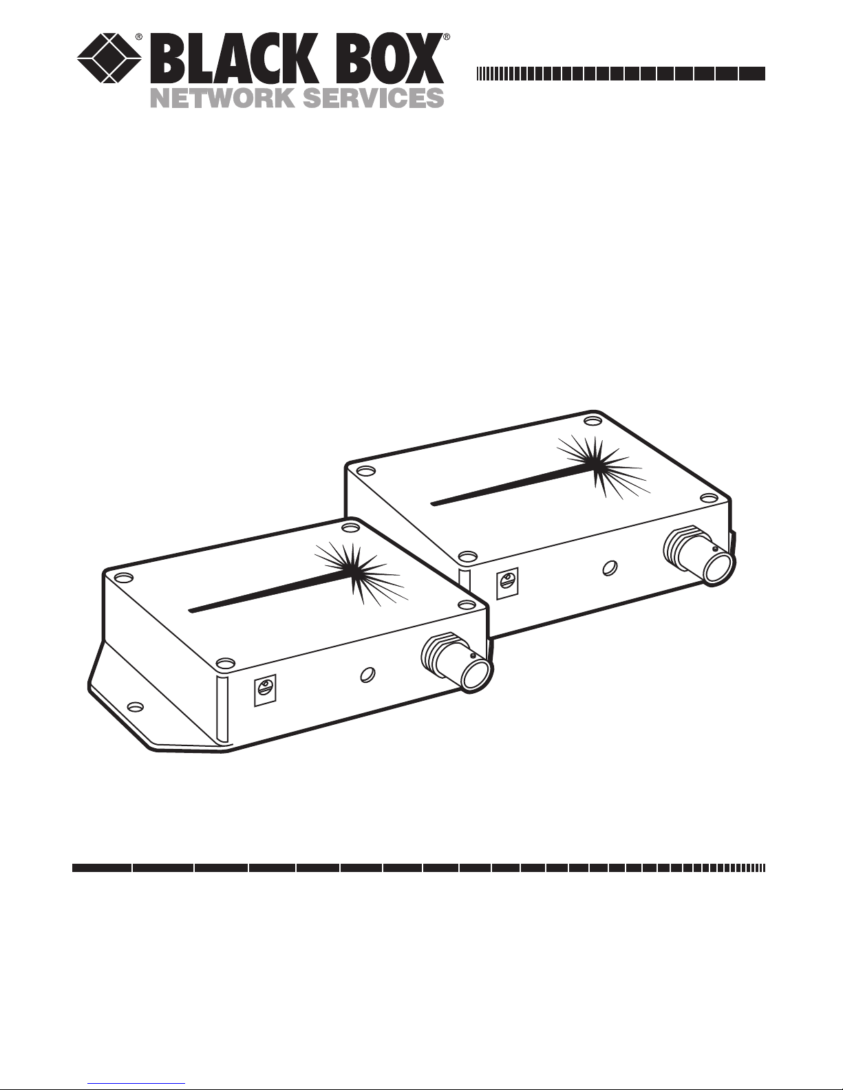
FiberPath
CUSTOMER SUPPORT INFORMATION
Order toll-free in the U.S. 24 hours, 7 A.M. Monday to midnight Friday: 877-877-BBOX
FREE technical support, 24 hours a day, 7 days a week: Call 724-746-5500 or fax 724-746-0746
Mail order: Black Box Corporation, 1000 Park Drive, Lawrence, PA 15055-1018
Web site: www.blackbox.com • E-mail: info@blackbox.com
POWER
FIBER IN
LEVEL
VIDEO
OUT
FiberPath
Optical Video Receiver
POWER
FIBER OUT
VIDEO
IN
FiberPath
Optical Video Transmitter
Page 2

1
FIBERPATH
FEDERAL COMMUNICATIONS COMMISSION
AND
INDUSTRY CANADA
RADIO FREQUENCY INTERFERENCE STATEMENTS
This equipment generates, uses, and can radiate radio frequency energy
and if not installed and used properly, that is, in strict accordance with the
manufacturer’s instructions, may cause interference to radio communication.
It has been tested and found to comply with the limits for a Class A computing
device in accordance with the specifications in Subpart J of Part 15 of FCC rules,
which are designed to provide reasonable protection against such interference
when the equipment is operated in a commercial environment. Operation of
this equipment in a residential area is likely to cause interference, in which case
the user at his own expense will be required to take whatever measures may be
necessary to correct the interference.
Changes or modifications not expressly approved by the party responsible
for compliance could void the user’s authority to operate the equipment.
This digital apparatus does not exceed the Class A limits for radio noise emission from
digital apparatus set out in the Radio Interference Regulation of Industry Canada.
Le présent appareil numérique n’émet pas de bruits radioélectriques dépassant les limites
applicables aux appareils numériques de classe A prescrites dans le Règlement sur le
brouillage radioélectrique publié par Industry Canada.
Page 3

2
FIBERPATH
NORMAS OFICIALES MEXICANAS (NOM)
ELECTRICAL SAFETY STATEMENT
INSTRUCCIONES DE SEGURIDAD
1. Todas las instrucciones de seguridad y operación deberán ser leídas antes
de que el aparato eléctrico sea operado.
2. Las instrucciones de seguridad y operación deberán ser guardadas para
referencia futura.
3. Todas las advertencias en el aparato eléctrico y en sus instrucciones de
operación deben ser respetadas.
4. Todas las instrucciones de operación y uso deben ser seguidas.
5. El aparato eléctrico no deberá ser usado cerca del agua—por ejemplo,
cerca de la tina de baño, lavabo, sótano mojado o cerca de una alberca,
etc..
6. El aparato eléctrico debe ser usado únicamente con carritos o pedestales
que sean recomendados por el fabricante.
7. El aparato eléctrico debe ser montado a la pared o al techo sólo como sea
recomendado por el fabricante.
8. Servicio—El usuario no debe intentar dar servicio al equipo eléctrico más
allá a lo descrito en las instrucciones de operación. Todo otro servicio
deberá ser referido a personal de servicio calificado.
9. El aparato eléctrico debe ser situado de tal manera que su posición no
interfiera su uso. La colocación del aparato eléctrico sobre una cama,
sofá, alfombra o superficie similar puede bloquea la ventilación, no se
debe colocar en libreros o gabinetes que impidan el flujo de aire por los
orificios de ventilación.
Page 4

3
FIBERPATH
10. El equipo eléctrico deber ser situado fuera del alcance de fuentes de calor
como radiadores, registros de calor, estufas u otros aparatos (incluyendo
amplificadores) que producen calor.
11. El aparato eléctrico deberá ser connectado a una fuente de poder sólo
del tipo descrito en el instructivo de operación, o como se indique en el
aparato.
12. Precaución debe ser tomada de tal manera que la tierra fisica y la
polarización del equipo no sea eliminada.
13. Los cables de la fuente de poder deben ser guiados de tal manera que no
sean pisados ni pellizcados por objetos colocados sobre o contra ellos,
poniendo particular atención a los contactos y receptáculos donde salen
del aparato.
14. El equipo eléctrico debe ser limpiado únicamente de acuerdo a las
recomendaciones del fabricante.
15. En caso de existir, una antena externa deberá ser localizada lejos de las
lineas de energia.
16. El cable de corriente deberá ser desconectado del cuando el equipo no
sea usado por un largo periodo de tiempo.
17. Cuidado debe ser tomado de tal manera que objectos liquidos no sean
derramados sobre la cubierta u orificios de ventilación.
18. Servicio por personal calificado deberá ser provisto cuando:
A: El cable de poder o el contacto ha sido dañado; u
B: Objectos han caído o líquido ha sido derramado dentro del
aparato; o
C: El aparato ha sido expuesto a la lluvia; o
D: El aparato parece no operar normalmente o muestra un cambio
en su desempeño; o
E: El aparato ha sido tirado o su cubierta ha sido dañada.
Page 5

4
FIBERPATH
TRADEMARKS
Any trademarks mentioned in this manual are
acknowledged to be the property of the trademark
owners.
Page 6

5
FIBERPATH
CONTENTS
1. Specifications . . . . . . . . . . . . . . . . . . . . . . . . . . . 6
2. Introduction. . . . . . . . . . . . . . . . . . . . . . . . . . . . 8
2.1 General . . . . . . . . . . . . . . . . . . . . . . . . . . . . . 8
2.2 What the Package Includes. . . . . . . . . . . . . 8
3. Installation . . . . . . . . . . . . . . . . . . . . . . . . . . . . . 10
4. Troubleshooting . . . . . . . . . . . . . . . . . . . . . . . . 13
Page 7

6
FIBERPATH
1. Specifications
Certification — For FiberPath: FCC Class A, Subpart
B of Part 155 compliance; For the power supply:
UL
®
, CSA listed
Input/Output Voltage — 1 volt pp (user-adjustable
at receiver)
Input/Output Impedance — 75 ohms
Signal/Noise Ratio (per RS-250) — 52 dB minimum
Differential Gain (per RS-250) — 2% typical
Differential Phase (per RS-250) — 1% typical
Optical Wavelength — 850 nanometers
Optical Cable and Connectors — 62.5-micron
multimode fiber with industry-standard ST
connectors
Optical Loss Budget — 12 dB minimum
Transmission Distance — 0 to 1.5 mile minimum
Page 8

7
FIBERPATH
Operating Power (per unit) — All units except
AC444AE: 12V ±10% D @ 100 ma max.; FiberPath
comes with two 115-VAC-to-12-VDC plug-in wall
adapters which can be used to supply all operating
power; AC444AE: (2) power supplies (receiver and
transmitter) that are 220 to 230 volts with special
international plugs, 50 Hz, 9 VDC @ 500 mA
Operating Temperature — -31 to +167°F
(-35 to +75°C)
Relative Humidity Tolerance — Up to 95%,
noncondensing
Size — 1"H x 2.375"W x 3.25"D (2.5 x 6 x 8.3 cm)
Weight — 0.5 lb. (0.2 kg);
Shipping weight: 1 lb. (0.45 kg)
Page 9

8
FIBERPATH
2. Introduction
2.1 General
The FiberPath is a high-quality, cost-effective fiberoptic
video transmission system designed to transmit color
and black-and-white signals over distances of more than
a mile. The system is easy to install and is designed for
long, trouble-free operation in most indoor or outdoor
protected environments. The FiberPath is compatible
with all standard analog video formats, including NTSC,
PAL, and SECAM, and will operate with all standard
62.5 micron fiberoptic cables and industry-standard ST
type connectors.
2.2 What the Package Includes
You can order the Transmitter and Receiver together or
separately. You need one Transmitter and one Receiver
to operate the system.
For the AC444A, your package includes:
• (1) FiberPath Transmitter
• (1) FiberPath Receiver
Page 10

9
FIBERPATH
• (2) 12-VDC Power Supplies
• This User Manual
For the AC444AE, your package includes:
• (1) FiberPath Transmitter
• (1) FiberPath Receiver
• (2) 220-to-230-Volt, 9-VDC Power Supplies
• This User Manual
For the AC445A-TX, your package includes:
• (1) FiberPath Transmitter
• This User Manual
For the AC446A-RX, your package includes:
• (1) FiberPath Receiver
• This User Manual
Page 11

10
FIBERPATH
3. Installation
Figure 3-1 on page 12 may provide assistance during
installation. Follow these steps:
1. Mount the FiberPath Transmitter at the camera
or source of video to be transmitted. Use the
mounting tabs on the housing or the enclosed
self-adhesive mounting pad.
2. Connect one of the plug-in power supplies to the
input connector on the FiberPath Transmitter. If
you plan to use an external power source, make
sure that it provides regulated 12-VDC ±10%.
Current from this source will not exceed 250 ma.
When power is applied, the red PWR LED
indicator will glow.
NOTE
The negative (-) side of the power input is connected to the
enclosure.
3. Connect the video signal to be transmitted to the
BNC connector on the FiberPath Transmitter, and
the ST fiberoptic cable plug to the transmitter’s
optical connector.
Page 12

11
FIBERPATH
4. Mount the FiberPath Receiver at the monitor or
device where the video will be received. Use the
mounting tabs on the housing or the enclosed
self-adhesive mounting pad.
5. Connect the remaining plug-in power supply to
the FiberPath Receiver’s input connector. If you
plan to use an external power source, make sure
it provides regulated 12-VDC ±10%. Current from
this source will not exceed 250 ma. When power
is applied, the red PWR LED indicator will glow.
NOTE
The negative (-) side of the power input is connected to the
enclosure.
6. Connect the video monitor or other video
receiving device to the BNC connector on the
FiberPath Receiver and the fiberoptic cable plug
to the optical connector on the Receiver.
7. For a pleasing picture, slowly adjust the LEVEL
control on the FiberPath Receiver. If you require
high accuracy, set this level to 1 volt pp with a
75-ohm load.
8. Your FiberPath video transmission system is now
installed.
Page 13

12
FIBERPATH
Figure 3-1. Installation of the FiberPath Fiberoptic Transmission
System.
DC Common +12VDC ±10%
CCTV Camera or other Video
Source
Video Monitor or Other
Receiver
Coaxial Cable
Coaxial Cable
Transmitter
12 VDC 12 VDC
ST Type
Optical
ST Type
Optical
Level
Adjust
Power
Adapter
Power
Adapter
Receiver
62.5 µ Fiberoptic Cable
Page 14

13
FIBERPATH
4. Troubleshooting
If your FiberPath transmission system does not
immediately operate, follow this checklist:
1. Is the correct operating power present and
connected to the proper pins on the power
connector? If so, the red PWR LED should glow.
2. If you’re using an external power source, does
it matter that the signal and power ground are
connected to the enclosure?
3. Is a video signal present at the FiberPath
Transmitter input?
4. Are you using the proper 62.5 micron fiberoptic
cable?
5. Is the fiberoptic cable more than 1.5 miles
(2.4 km) long? If so, a weak, snowy picture
may result.
6. Are the fiberoptic connector ends free of any
minute dust or dirt particles? If not, use a lint-free
cloth moistened with a drop of alcohol to gently
clean the optical surface.
Page 15

14
FIBERPATH
If all of the troubleshooting items on the checklist are
correct and the system still will not operate correctly, call
Black Box Technical Support at 724-746-5500.
Page 16

1000 Park Drive • Lawrence, PA 15055-1018 • 724-746-5500 • Fax 724-746-0746
© Copyright 2000. Black Box Corporation. All rights reserved.
 Loading...