

Page 1
CUSTOMER
SUPPORT
INFORMATION
Order toll-free in the U.S. 24 hours, 7 A.M. Monday to midnight Friday: 877-877-BBOX
FREE technical support, 24 hours a day, 7 days a week: Call 724-746-5500 or fax 724-746-0746
Mail order: Black Box Corporation, 1000 Park Drive, Lawrence, PA 15055-1018
Web site: www.blackbox.com • E-mail: info@blackbox.com
MAY 1998
AC321A
AC321AE
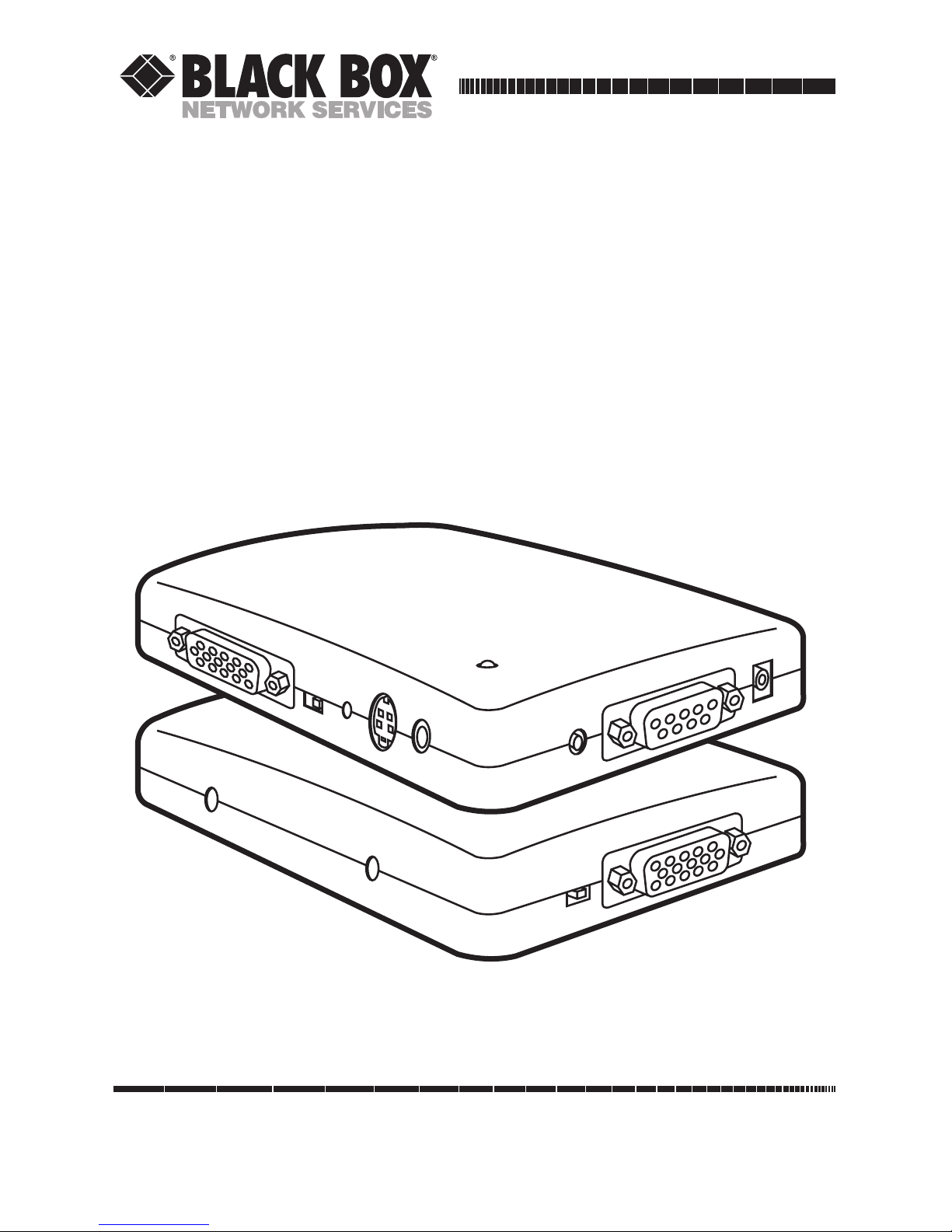
VGA to Video Portable Plus
VGA to Video Portable Plus
AUDIO OUT
MIC IN
VGA IN
50 Hz
60 Hz
VGA to Video Portable Plus
VIDEO
OUT
RGB VIDEO OUT
DC 9V IN
BRIGHT
S-OUT
PHASE
ADJ.
VGA OUT
PAL
NTSC
Page 2

VGA to Video Portable Plus
FEDERAL COMMUNICATIONS COMMISSION
AND
INDUSTRY CANADA
RADIO FREQUENCY INTERFERENCE STATEMENT
Class B Digital Device. This equipment has been tested and found to comply with the
limits for a Class B computing device pursuant to Part 15 of the FCC Rules. These
limits are designed to provide reasonable protection against harmful interference in a
residential installation. However, there is no guarantee that interference will not occur
in a particular installation. This equipment generates, uses, and can radiate radio
frequency energy, and, if not installed and used in accordance with the instructions,
may cause harmful interference to radio communications. If this equipment does
cause harmful interference to radio or telephone reception, which can be determined
by turning the equipment off and on, the user is encouraged to try to correct the
interference by one of the following measures:
• Reorient or relocate the receiving antenna.
• Increase the separation between the equipment and receiver.
• Connect the equipment into an outlet on a circuit different from that
to which the receiver is connected.
• Consult an experienced radio/TV technician for help.
Caution:
Changes or modifications not expressly approved by the party
responsible for compliance could void the user’s authority to operate the
equipment.
To meet FCC requirements, shielded cables and power cords are required to connect
this device to a personal computer or other Class B certified device.
This digital apparatus does not exceed the Class B limits for radio noise emission from
digital apparatus set out in the Radio Interference Regulation of Industry Canada.
Le présent appareil numérique n’émet pas de bruits radioélectriques dépassant les limites
applicables aux appareils numériques de la classe B prescrites dans le Règlement sur le
brouillage radioélectrique publié par Industrie Canada.
Page 3

VGA to Video Portable Plus
README
The README file on the VGA to Video Portable Plus Utility diskette
contains information about the latest changes and revisions. To view this
file, insert the utility diskette in to drive A or B and type:
A: README [ENTER]
or
B: README [ENTER]
TRADEMARKS
IBM®and PS/2®are registered trademarks of IBM Corporation.
MS-DOS®is a registered trademark of Microsoft Corporation.
Windows
®
is a trademark of Microsoft Corporation.
Page 4

VGA to Video Portable Plus
Contents
Chapter Page
1. Specifications....................................................................................................1
2. Introduction .....................................................................................................4
2.1 VGA to Video Portable Plus.....................................................................4
2.2 System Requirements...............................................................................4
2.3 Features.....................................................................................................5
2.4 Package Contents .....................................................................................5
3. Installation........................................................................................................6
3.1 Hardware Installation ..............................................................................6
3.2 Software Installation.................................................................................9
4. Software Operation........................................................................................10
4.1 Software Description..............................................................................10
4.1.1 BBOXP.COM...........................................................................10
4.1.2 AUTOSAVE. COM ..................................................................10
4.1.3 SETPATH.COM ......................................................................10
4.1.4 SETKEY.COM ..........................................................................10
4.1.5 SETNTSC.COM.......................................................................11
4.1.6 SETPAL.COM..........................................................................11
4.2 Using the Hotkeys ..................................................................................12
5. Signal Adjustment..........................................................................................13
5.1 Phase Adjustment...................................................................................13
5.2 Brightness Adjustment...........................................................................13
5.3 50/60 Hz Switch (Field Range Adjust Switch) .....................................13
6. Sizing Windows to Fit Your Screen ...............................................................14
7. Troubleshooting ............................................................................................16
7.1 Common Questions ...............................................................................16
7.2 If You Have Problems.............................................................................17
Page 5

1
Chapter 1: Specifications
Resolution — NTSC (North America) supports up to
640 x 480 16/256/32K/64K/16M colors;
PAL (Europe) supports up to 800 x 600
16/256/32K/64K colors
Memory Requirements — 640K RAM
System Requirements — MS-DOS®ver. 3.3 or later; Windows™3.1
optional
Monitor — VGA or S-VGA
Hardware Requirements — IBM®PC compatible, 286, 386, 486 with
VGA display card or CRT port of notebook
computer or IBM PS/2®; floppy-disk drive,
hard disk recommended
Video Input Standards — VGA analog input from VGA card or CRT
port of notebook computer; Microphone
input (capacitance-type microphone)
Video Output Standards — NTSC or PAL (switch-selectable); Composite
Video, and S-Video; VGA signal passthrough; Audio output; Analog RGB video
with special-order cable
Audio Out — 52 dB amplifier with microphone input;
Maximum output: 3Vpp
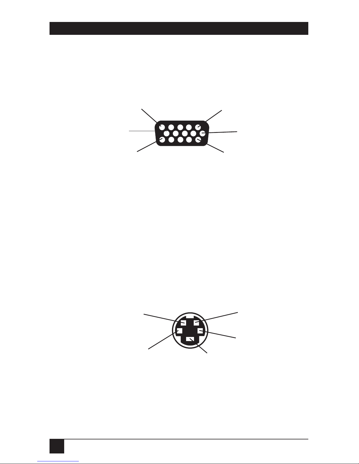
VGA IN Connector — Analog RBG Signal from DB15HD VGA
output port of PC or notebook PC
Pin Number Signal Description
1 Red, 0.7 Vpp, 75 ohms
2 Green, 0.7 Vpp, 75 ohms
3 Blue, 0.7 Vpp, 75 ohms
4 Monitor Id2, TTL level
5 GND
6 GND
7 GND
8 GND
1. Specifications
Page 6
2
VGA to Video Portable Plus
9 No connection
10 GND
11 Monitor ID0, TTL level
12 Monitor ID1, TTL level
13 HSYNC, TTL level
14 VSYNC, TTL level
15 No connection
VGA IN Connector.
VGA OUT Connector — DB15 female connector; pin assignment is
the same as VGA IN connector; connect to
VGA monitor
VIDEO OUT Connector — Composite video out, 1.0 Vpp ±0.2 Vpp,
75 ohms, negative sync
S-OUT Connector — 4-pin mini-DIN connector
Pin Number Signal Description
1 (C) GND
2 (Y) GND
3 Y (Luminance), 0.7 V pp±0.2 Vpp, 75 ohms,
negative sync
4 C (Chrominance), 0.3 Vpp ±0.1 Vpp
Female S-OUT.
5
11
10
15
1
6
4
2
Key
1
3
Page 7

3
Chapter I: Specifications
RGB VIDEO Connector — DB9 female connector.
Pin Number Signal Description
1 GND
2 No Connection
3 Red, 0.7 Vpp ±0.2 Vpp, 75 ohms
4 Green, 0.7 Vpp ±0.2 Vpp, 75 ohms
5 Blue, 0.7 Vpp ±0.2 Vpp, 75 ohms
6 Composite Sync, TTL level, negative sync
7 Composite Sync, 1V, 75 ohms, negative sync
8 TV HSYNC, TTL level, negative sync, 15734 Hz
in NTSC, 15625 Hz in PAL
9 TV VSYNC, TTL level, negative sync, 60 Hz in
NTSC, 50 Hz in PAL
Software — TSR Utility (VGA to Video Portable Plus
Installation Disk)
Power — 115/230 VAC, 60/50 Hz, 12 watts (power
consumption 5 watts, excluding DC
adapter); secondary 9 VDC @ 650/600 mA
Size — 2.4"H x 12.5"W x 8"D (6.1 x 31.8 x 20.3 cm)
Weight — 0.3 lb. (0.1 kg)
Page 8

4
VGA to Video Portable Plus
2.1 VGA to Video Portable Plus
With the VGA to Video Portable Plus, you can display a VGA signal on a
television set or monitor, or you can record a VGA picture on a VCR. At the
same time, you can still see the display on your original VGA monitor. To
begin, all you need to do is connect the cables and install the VGA to Video
Portable Plus Utility Program.
The VGA to Video Portable Plus comes with a diskette that contains the utility
software. This software is a TSR (Terminate-Stay-Resident) type program.
After you install the VGA to Video Portable Plus program, you’re ready to
use the VGA to Video Portable Plus.
Your VGA to Video Portable Plus includes a lavaliere microphone and has
a built-in microphone input and audio output. It’s ideal for presentations,
training, and exhibitions. VGA to Video Portable Plus turns a computer into
a complete presentation system, replacing slides, projectors, and overhead
projectors. Use the TV or VCR sound, or connect to a public-address sound
system for large audience presentations.
2.2 System Requirements
• IBM PC or compatible 286, 386, or 486 with VGA Display Card 640 x 480
resolution, compatible, notebook, laptop computer, or IBM PS/2.
• Floppy-disk drive.
• Hard disk (recommended).
• 640 KB RAM.
• MS-DOS ver. 3.3 or later.
• VGA monitor (31.5 KHz).
• TV, VCR, or large-screen display with composite Video input (RCA jack),
S-Video input, or Analog RGB Video input.
• TV, VCR, or large-screen display with audio input or Audio Auxiliary input
on any mixer or PA system.
2. Introduction
Page 9

5
Chapter 2: Introduction
2.3 Features
- Supports VGA mode:
• Supports standard VGA mode (0-13).
• NTSC system supports up to 640 x 480 in 16, 256, 32,000, 64,000,
or 16 million colors.
• PAL system supports up to 800 x 600 in 16, 25, 32,000, or 64,000
colors.
- Can transfer Microsoft Windows overlay video signal to your video display.
- You can see the same image on the TV and your VGA monitor
simultaneously.
- Compatible with most VGA chips.
- Simultaneous composite video, S-Video, and RGB Video output.
- For most applications, you won’t have to change your configuration.
- With the TSR software, simple hotkeys move the screen, switch between
interlaced and noninterlaced modes, change the text font, and invoke the
memory function.
- PAL TV system field rate can be changed to 60 Hz, to eliminate field
flicker.
- Lavaliere microphone included for audio presentations.
- NTSC or PAL, switch-selectable.
2.4 Package Contents
•3-m (9.8-ft.) S-Video cable •AC/9VDC power adapter
•Lavaliere microphone •Small screwdriver
•3-m (9.8-ft.) RCA Video cable •This user’s manual
•VGA to Video Portable Plus converter box
•3-m (9.8-ft.) stereo audio cable w/RCA phono plugs
•Floppy diskette (Video to Portable Plus TSR Utility and Program)
•1-ft. (30.5-cm) DB15 male-to-male VGA pass-through cable
Page 10

6
VGA to Video Portable Plus
The VGA to Video Portable Plus (Figure 1) has one input connector and
three output connectors. VGA IN connects with the VGA output of a PC or
notebook computer. VGA OUT connects to a VGA monitor. There are three
video outputs: Video, S-Video, and RGB Video.
The VGA to Video Portable Plus has two switches. One selects either the
NTSC or the PAL broadcast system. The other changes the field rate to
50 or 60 Hz. (See Section 5.3 for more information.)
3.1 Hardware Installation
1. Turn off the power to your laptop, notebook, or desktop PC.
2. Make sure the NTSC/PAL switch is set to the correct
position, either NTSC (U.S.) or PAL (Europe).
3. If your TV system is PAL, set the Field Scan Rate to 50 Hz. If your
system is NTSC, set it to 60 Hz.
4. Connect one end of the DB15 cable to your computer’s VGA output,
and the other to “VGA IN” on the VGA to Video Portable Plus.
5. With one of the supplied video cables, connect “VIDEO OUT” on the
VGA to Video Portable Plus to your TV or VCR’s video input.
NOTE
The VGA to Video Portable Plus supports high-quality S-VHS and RGB
Video. If your TV or VCR supports “S-VIDEO IN” or “RGB VIDEO IN,” we
recommend using them for the best results.
6. Connect your VGA monitor cable to the VGA to Video Portable Plus
“VGA OUT” connector on the VGA to Video Portable Plus.
7. Power on your computer.
8. Plug the 9V power adapter to the “DC 9V in” connector, and into a
standard AC outlet.
9. Turn on your TV or VCR, and switch the channel to the “VIDEO
IN.” Refer to the connections diagram on page 8.
10. Follow the instructions in Section 3.2 to install the VGA to Video
Portable Plus Utility diskette.
3. Installation
Page 11

7
Chapter 3: Installation
Figure 1. The VGA to Video Portable Plus.
VGA to Video Portable Plus
AUDIO OUT
MIC IN
VGA IN
50 Hz
60 Hz
VGA to Video Portable Plus
VIDEO
OUT
RGB VIDEO OUT
DC 9V IN
BRIGHT
S-OUT
PHASE
ADJ.
VGA OUT
PAL
NTSC
Page 12

8
VGA to Video Portable Plus
Figure 2. VGA to Video Portable Plus System Connections.
VCR
S-Video
TV
RGB Monitor/
Projection TV
VGA
Monitor
Lavaliere
Microphone
Laptop
MIC IN
VGA IN
Video
OUT
Video
IN
Video
IN
Video
IN
Audio
IN
Audio
IN
Audio
IN
RGB
OUT
286, 386, 486
VGA
OUT
VGA
OUT
VGA
OUT
Audio
OUT
VGA to Video
Portable Plus
Page 13

9
Chapter 3: Installation
3.2 Software Installation
1. Insert the “VGA to Video Portable Plus Utility diskette” into floppy
disk drive A or B.
2. At the DOS prompt, type:
A:\INSTALL/N [ENTER] (for installing NTSC system) or
A:\INSTALL/P [ENTER] (for installing PAL 50-Hz system in Europe),
OR
B:\INSTALL/N [ENTER] (for installing NTSC system) or
B:\INSTALL/P [ENTER] (for installing PAL 50-Hz system in Europe.)
NOTE
Put the 50/60 Hz switch in the 50-Hz position when using the
PAL system.
3. Follow the instructions until the installation process is completed. We
recommend that you make a backup copy of the distribution diskette.
Page 14

10
VGA to Video Portable Plus
4. Software Operation
4.1 Software Description
To show your VGA image on the TV screen, all you have to do is type
“BBOXP” from DOS. That activates the VGA to Video Portable Plus driver,
BBOXP.COM. There are also other programs for specific functions.
4.1.1 BBOXP.COM
•“BBOXP” installs the VGA to Video Portable Plus driver. It also transfers
the VGA picture to the TV screen.
•“BBOXP/U” releases the VGA to Video Portable Plus driver from the
computer’s main memory.
•“BBOXP?” lists all operational information of the VGA to Video Portable
Plus software.
4.1.2 AUTOSAVE.COM
The Autosave function saves the position of the screen to the BBOXP.COM
file when you adjust the position of screen.
•“AUTOSAVE/E” enables the Autosave function.
•“AUTOSAVE/D” disables the Autosave function.
4.1.3 SETPATH.COM
If you move the VGA to Video Portable Plus driver to another directory, run
this program to reorganize your directories and files.
4.1.4 SETKEY.COM
“SETKEY” is used in the following situations:
• You want to change the hotkey sequence.
• You use the present hotkey sequence, but there is conflict with a default
hotkey already used for another function on the computer.
Page 15

11
Chapter 4: Operation
4.1.5 SETNTSC.COM
Set the VGA to Video Portable Plus driver to NTSC system.
4.1.6 SETPAL.COM
Set the VGA to Video Portable Plus driver to PAL (50 Hz) system.
Page 16

12
VGA to Video Portable Plus
4.2 Using the Hotkeys
After you’ve typed “BBOXP” to activate the driver, this message appears.
Video to Portable Plus TSR Driver Version 3.09 (NTSC or
PAL)
HOTKEY FUNCTION:
Alt—Shift—UP-Arrow ==> Scroll the Screen UP
Alt—Shift—DOWN-Arrow ==> Scroll the Screen DOWN
Alt—Shift—LEFT-Arrow ==> Scroll the Screen LEFT
Alt—Shift—RIGHT-Arrow==> Scroll the Screen RIGHT
Alt—Shift—Page-Up ==> Scroll the Screen to the TOP
Alt—Shift—Page-Down ==> Scroll the Screen to the BOTTOM
Alt—Shift—F ==> Toggle Text Font (for text mode)
Alt—Shift—D ==> Change Screen Size (Toggle 50/60
Hz)
Alt—Shift—R ==> Reset Screen Position
Alt—Shift—T ==> Flicker Free Switch
• You can use the [Alt] + [Shift] + [Arrow] (or [Page Up], [Page Down])
keys to adjust the position of the image on the screen.
• You can use the [Alt] + [Shift] + [F] keys to toggle the size of the text font
(only used for text mode).
• You can use the [Alt] + [Shift] + [D] keys to change the size of the image
on the TV screen (only used for PAL system, or Multi-System TV).
NOTE
After pressing the [Alt] + [Shift] + [D] keys, you must slide the Field Scan
Rate switch to 60 Hz. If you press the hotkey again, slide the Field Scan
Rate switch back to 50 Hz. If you don’t, you’ll have an unreadable
television picture.
• You can use the [Alt] + [Shift] + [R] keys to reset the position of the
image on your TV screen.
• You can use the [Alt] + [Shift] + [T] keys to switch to an interlaced or
non-interlaced system.
Page 17

13
Chapter 5: Signal Adjustment
5. Signal Adjustment
5.1 Phase Adjustment
When there’s no color or a rainbow pattern on the TV, use the screwdriver
(included) to adjust the burst signal’s phase. “The PHASE ADJ.” control is
next to the S-OUT connector (see Figure 1 on page 7).
5.2 Brightness Adjustment
Brightness is factory-preset. If you need to adjust the brightness or correct
horizontal or vertical striping, use the screwdriver to adjust the “BRIGHT”
control (next to the RGB VIDEO OUT connector—see Figure 1 on page 7).
5.3 50/60 Hz Switch (Field Range Adjust Switch)
This switch supports two functions. In a standard PAL system, the field-scan
rate (vertical sync frequency) is 50 Hz. PAL has more field flicker than NTSC
(60 Hz). If your TV is multi-system and supports PAL (60 Hz) or the NTSC
4.43-MHz system, you can slide this switch to the 60 Hz position and then
press <Alt-Shift-D>. The VGA to Video Portable Plus changes to PAL (60 Hz)
or NTSC (4.43 MHz). This expands your TV picture vertically and produces
less field flicker.
The 50/60 Hz switch is used to eliminate noise in NTSC systems. However,
the VGA output level differs from computer to computer. If you hear
unwanted noise on your TV, slide this switch to the other side.
Page 18

14
VGA to Video Portable Plus
6. Sizing Windows to Fit Your Screen
To make Microsoft Windows software easier to see on the TV, you might have
to change the sizes of the windows. If you’re not familiar with Windows, the
following information will help you adjust the window size so that it fits
properly in the television screen.
The Sizing Buttons are found in the upper right corner of the window in
Restored Mode. The button on the left will minimize the window, so that it
appears as an icon at the bottom of the screen. The button on the right is
for maximizing window size, so that the window fills the whole screen.
Instead of aiming for the maximize button, you can also maximize a window
by double-clicking its title bar. Similarly, you can restore a maximized
application by double-clicking its title bar.
The Buttons in Maximized Mode look like the ones pictured below. The
double-headed arrow on the right is the restore button, which restores the
window to the size it was before you maximized it. The arrow on the left
minimizes the window to an icon.
NOTE
Sizing must be done while the window is in Restored Mode. It isn’t
possible to adjust the window’s size in Maximized Mode. If you need to
adjust the window size and you’re in Maximized Mode, you must click the
double-headed arrow to return to Restored Mode.
▲
▼
▼
▲
▼
Page 19

15
To change the size of a window with the mouse, simply position the pointer on the
border you want to adjust. The mouse pointer changes from a single-headed
arrow to a double-headed one. Press and hold the left button, move the
border as you please, and then release the button.
You can also move two adjacent borders at once by positioning the mouse
pointer in the corner between those borders.
To change a window’s size with the keyboard, start by pressing [Alt] +
[Spacebar] + [S]. A four-headed pointer will appear in the center of the
window. Use one of the direction keys to move that pointer to the border
whose position you want to adjust. Then use direction keys to adjust the
border. When you have the border where you want it, press [Enter].
To cancel a sizing operation, press [Esc] before releasing the mouse button
or pressing [Enter].
Chapter 6: Sizing Windows to Fit Your Screen
Page 20

16
VGA to Video Portable Plus
7. Troubleshooting
7.1 Common Questions
Q: My TV doesn’t have an RCA jack (composite video connector). How can I
connect the PC to the TV converter?
A: Connect through your VCR as follows:
1. Connect the VGA to Video Portable Plus according to the
connection diagram shown on page 8; however, connect the
composite video cable to the Video In RCA jack on the VCR.
2. Power on the VCR and TV. Switch the TV to the channel that
takes VCR input. Play a tape for a moment on the VCR to make sure
you can see the program on the TV screen; then remove the tape
from the VCR.
3. Set the VCR to Video Mode (a VCR generally has three input
sources: Video, TV, and Tape).
4. On your computer, type “BBOX” to invoke the VGA to Video
Portable Plus driver and switch to TV display. If you can’t get a stable
display, adjust the screen synchronization with the hotkeys as
described in Section 4.2.
Another option is the RF modulator method. An RF modulator can convert
a composite video signal to an RF signal which can be used as antenna input
(VHF/UHF) on the TV. You can get an RF modulator at any good electronics
store.
Q: Why does the TV screen only show a gray image?
A: The chrominance of your PC to TV Converter has run out of range.
This can be fixed by adjusting the signal. Please refer to Section 5.1.
Q: Why aren’t text and images displayed at the top of the screen?
A: Overscan may be occurring in an NTSC system. This happens because
the VGA has more display lines than the TV can display. In general, a TV has
only 420 lines, whereas VGA has 480 lines in 640 x 480 mode. Images may be
out of range or truncated. Use the hotkeys (see Section 4.2) to adjust the
screen position to get the picture on top or bottom. This phenomenon also
happens in the PAL system; VGA is 800 x 600 mode.
Q: Why does the display shrink in a PAL system?
A: PAL systems have 625 scan lines. If your VGA card is set for a 640 x 480
display, there’s no problem. If the display is 200 lines (320 x 200), however,
the image will shrink.
Page 21

17
Chapter 7: Troubleshooting
Q: How can I enhance the display quality?
A: You can adjust the TV’s “Contrast” and “Sharpness” controls. For the
best results, lower the “Brightness” control to minimize flicker effect.
Q: Why does the TV have some noise lines and how can I eliminate them?
A: Adjust the Brightness control on the VGA to Video Portable Plus.
Q: My notebook PC supports simu-scan function. Why don’t the hotkeys
work?
A: Most notebook PC LCD VGA controllers lock the CRT parameter to
60 Hz, so the BBOXP utility can’t adjust positions. Set the notebook to CRT
output only; then the BBOXP utility should work normally.
7.2 If You Have Problems
Sometimes a minor adjustment is all it takes to eliminate problems you’re
having with the VGA to Video Portable Plus. Refer to the chart below for
possible solutions. If you are still having problems, contact your dealer.
Symptom Did You Check... Solution
No picture on the ...that the power adapter Plug in the adapter.
TV or VGA monitor. is plugged in?
..that the VGA pass-through Connect the cable.
cable is connected?
Rainbow pattern Use a screwdriver to
on TV. ________________ adjust the Phase Adjust
knob.
No picture on the ...if the video cable or Make a secure
TV, but there is one S-Video cable is connection.
on the VGA monitor. connected properly to
the TV?
...the TV input source? Select the proper input.
The TV’s picture is ...the NTSC/PAL switch? Make sure the switch is
abnormal (unread- set properly to your TV
able or no picture). system.
...the Field Scan Rate Set the switch to the
switch? right position (50 or 60).
Page 22

1000 Park Drive • Lawrence, PA 15055-1018 • 724-746-5500 • Fax 724-746-0746
© Copyright 1998. Black Box Corporation. All rights reserved.
 Loading...