

Page 1

Chapter
Order toll-free in the U.S.: Call 877-877-BBOX (outside
U.S. call 724-746-5500) FREE technical support 24
hours a day, 7 days a week: Call 724-746-5500 or fax
724-746-0746 Mailing address: Black Box Corporation,
1000 Park Drive, Lawrence, PA 15055-1018 Web site:
www.blackbox.
com • E-mail: info@blackbox.com
Customer
Support
Information
Combines video, audio, and serial functions
for distributing real-time multimedia content
from a player to multiple screens up to 2000
feet (600 m) away.
HD View™ Quick Start Guide
AC3000A-R2–AC3016A-R2
Series
This manual includes information for these product codes:
AC3000A-R2, AC3008A-R2, AC3016A-R2, AC3003A-R2,
and AC3004A-R2.
Page 2

724-746-5500 | blackbox.com
Page 2
Trademarks Used in this Manual
Trademarks Used in this Manual
Black Box and the Double Diamond logo are registered
trademarks, and HD View is a trademark, of BB Technologies,
Inc.
Any other trademarks mentioned in this manual are
acknowledged to be the property of the trademark owners.
Page 3

724-746-5500 | blackbox.com Page 3
Table of Contents
Chapter Page
1. System Overview ............................................................ 4
1.1 Transmitter ........................................................... 5
1.2 Receivers ............................................................... 6
1.3 Line Splitter Long Range (LR) ............................... 8
1.4 LEDs .................................................................. 9
1.5 Pre-Installation Guidelines.................................. 10
2. Connecting the Cables ................................................. 11
2.1 Transmitter Connections .................................... 12
2.2 Receiver/Receiver LR Connections ..................... 12
3. Connecting CATx Cables .............................................. 13
3.1 Connecting the Transmitter ............................... 13
3.2 Connecting to a Line Splitter LR ........................ 13
3.3 Connecting to the Power Supply ....................... 13
3.4 Adjusting the Picture Quality ............................. 13
3.5 Note on Serial Extension .................................... 13
4. Updates on Revision 3 .................................................. 14
Page 4
724-746-5500 | blackbox.com
Page 4
Chapter 1: System Overview
1. System Overview
Figure 1-1 provides an overview of the system, showing a
Transmitter, Long-Range (LR) Line Splitter, and different Receiver
types.
Receiver
Line Splitter
Long
CATx cables
to receivers
Screen
Serial port/
device
Audio
CATx cables to
receivers or line
splitters
CATx cable
to receiver
HD View
Transmitter
Player
computer
Video cable
Audio cable
Serial ext. cable
Figure 1-1. HD View system overview.
NOTE: You can cascade line splitters only. The transmitters have
a local VGA output that can feed another transmitter. If
you need more ports, use a line splitter which will allow a
single audio/video/serial channel to split out to 8 or 16
outputs. Cascade up to 8 levels of line splitters to reach
thousands of potential outputs.
Page 5

724-746-5500 | blackbox.com Page 5
Chapter 1: System Overview
1.1 Transmitter
Three Transmitter models are available:
• 1-Port Transmitter (part number AC3000A-R2)
• 8-Port Transmitter (part number AC3008A-R2)
• 16-Port Transmitter (part number AC3016A-R2)
Figures 1-2 and 1-3 illustrate the 8-Port Transmitter. The ports
are the same for the Transmitter 1-port, 8-port, and 16-port
models, except for the number of system ports. The
AC3000A-R2 has one system port, the AC3008A-R2 has eight
System ports, and the AC3016A-R2 has sixteen system ports.
Table 1-1 describes the transmitter’s components.
1
Figure 1-2. Transmitter Unit—8-port, front view.
2 3 4 5 6
7 8
Figure 1-3. Transmitter Unit—8-port, back view.
Page 6

724-746-5500 | blackbox.com
Page 6
Chapter 1: System Overview
Table 1-1. Transmitter Unit—8-port components.
Number Component Description
1 Power LED Lights when power is on
2 Power connector Links to 12-VDC power
3 RJ-11 connector
Connects to serial
download cable
4 Audio
Links to stereo audio
input
5 HD15 connector Links to video in
6 RJ-45 connectors Link to system cables
7 DB9 connector Connects to serial cable
8 HD15 connector
Connects to local video
out
1.2 HD View Receivers
The HD View Receivers come in the following models:
• HD View Receiver (part number AC3003A-R2 or AC3003A-
NEC). It can be up to 330 ft. (100 m) from the Transmitter.
• HD View Receiver—LR (part number AC3004A-R2 or
AC3004A-NEC). It can be up to 1000 ft. (300 m) from the
Transmitter.
Figure 1-4 illustrates the Receiver ports. Table 1-2 describes their
components.
Page 7

724-746-5500 | blackbox.com Page 7
Chapter 1: System Overview
1 2 3 4 5 6
Figure 1-4. AC3003A-R2 back view.
Table 1-2. AC3003A-R2 receiver components.
Number Component Description
1 Power connector Links to 12-VDC power
2 RJ-11 connector Tuning
3 RJ-45 connector Links to system cable
4 HD15 connector
Links to video cable
output
5 Audio connector
Links to mono audio
output
6 DB9 connector Links to serial cable
NOTE: In Version 3, both products have the same ports. Refer to
the part number to be sure that a receiver is a Standard
Receiver (AC3003A-R2) or LR Receiver (AC3004A-R2).
Page 8

724-746-5500 | blackbox.com
Page 8
Chapter 1: System Overview
1.3 Line Splitter Long-Range (LR)
NOTE: With the LR Splitter, the maximum distance is 2000 feet
(600 m). The last cascaded LR line splitter must not be
further than 1000 feet (300 m) from the transmitter.
Add Line Splitters LR to use for clusters or to increase the
number of Receivers in the system. You can cascade Line
Splitters to Line Splitters. Figures 1-5 and 1-6 illustrate the Line
Splitter LR ports. Table 1-3 describes the components.
1
Figure 1-5. Line Splitter (AC3002A-R2), front view.
2 3 4 5
6
Figure 1-6. Line Splitter (AC3002A-R2), back view.
Page 9

724-746-5500 | blackbox.com Page 9
Chapter 1: System Overview
Table 1-3. Line Splitter (AC3002A-R2) components.
Number Component Description
1 Power LED Lights when power is on
2 Power connector Links to 12-VDC power
3 RJ-11 connector Tuning
4 RJ-45 connector System in
5 RJ-45 connectors Link to system out cables
1.4 LEDs
Table 1-4 explains the functions of all the LEDs of the units in the
system.
Table 1-4. LED functions.
Unit LED Function
Transmitter Front panel—Green
Lights green when power
is on
Lights yellow when a link
is established
NOTE: Table 1-4 is continued on the next page.
Page 10

724-746-5500 | blackbox.com
Page 10
Chapter 1: System Overview
Table 1-4 (Continued). LED functions.
Unit LED Function
Receiver,
Receiver LR
RJ-45 system port—
Green/Yellow
Lights green when power
is on.
Lights yellow when a link
is established. This LED will
blink yellow intermittently.
Blinks yellow constantly to
indicate bidirectional
RS-232 communication.
(This is only possible with
one Receiver/Receiver LR
at a time.)
Line
Splitter LR
Rear panel: RJ-45
system port—
Green/Yellow
Lights green when power
is on.
Blinks yellow when a link
is established.
1.5 Pre-Installation Guidelines
• Place cables away from fluorescent lights, air conditioners, and
machines that are likely to generate electrical noise.
• Do not bend the cable in a way that it can be damaged.
• While using tie wraps to hold the cables in place, make sure
not to pull them too tight, because this can damage the cable.
• For best performance, the specifications of the cable should be:
- Gage: 24 AWG (should be written on the cable)
- Wire: solid wire (should be written in the spec. of the cable)
- For cable runs over 330 feet (100 m), the SKEW delay of the
cable should be no more than 20 ns per 330 feet (100 m) (this
should be written in the spec of the cable).
Page 11

724-746-5500 | blackbox.com Page 11
Chapter 2: Connecting the Cables
2. Connecting the Cables
The figures below illustrate the versatility of the HD View system.
Figure 2-1 shows a basic installation with a Receiver and
Receiver—LR. Receivers can be up to 328 feet (100 m) away
from the Transmitter. The Receiver—LR can be up to 1000 feet
(300 m) away from the Transmitter.
PC
Transmitter
(AC3008A-R2)
Receiver
(AC3003A-R2)
1000 ft. (304.8 m)
CATx cable
Receiver—LR
(AC3004A-R2)
NEC display with expansion
and AC3003A-NEC
330 ft. (100 m)
330 ft. (100 m)
Figure 2-1. HD View basic installation.
Figure 2-2 shows a Line Splitter—LR with connected Receivers
up to 1000 ft. (304.8 m) from the Transmitter.
PC
Transmitter
(AC3008A-R2)
1000 ft. (304.8 m) CATx cable
Line Splitter—LR
(AC3002A-R2)
NEC display with expansion
and AC3004A-NEC
Receiver—LR
(AC3004A-R2)
Figure 2-2. Long cluster.
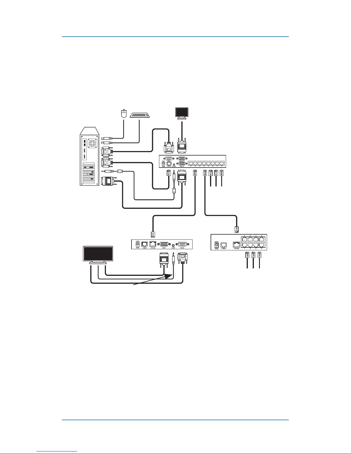
Figure 2-3 shows an installation with the Line Splitter, Line
Splitter—LR, Receiver, and Receiver—LR.
Page 12

724-746-5500 | blackbox.com
Page 12
Chapter 2: Connecting the Cables
NEC display with expansion
and AC3003A-NEC
PC
Transmitter/
Broadcaster
Receiver
(AC3003A-NEC)
330 ft. (100 m)
Receiver
(AC3002A-R2)
1000 ft. (300 m)
330 ft. (100 m)
AC3002A-R2
Figure 2-3. Installation.
2.1 Transmitter Connections
1. Connect the video cable to the transmitter’s Video In port and
the computer’s Video card.
2. Connect the serial extender cable to the transmitter’s Serial In
port and the computer’s Serial port.
3. Connect the stereo audio cable to the transmitter’s Audio In
port and the computer’s Line Out port.
4. To use the video service utility, connect the serial download
cable to the transmitter’s Control port and the computer’s
Serial port.
5. (Optional) Connect a monitor to the transmitter’s Video Out
port.
2.2 Receiver/Receiver LR Connections
1. Connect the screen to the Video port.
2. Connect the audio/speakers to the Audio port.
NOTE: If you are connecting the audio out of the receivers to
speakers, they must have an internal amplifier. The audio
out is a line out extension of the player.
3. Where relevant, attach the Serial connection to the Serial
port.
Page 13

724-746-5500 | blackbox.com Page 13
Chapter 3: Connecting CATx Cables
3. Connecting CATx cables
3.1 Connecting the Transmitter
Connect CATx cables to the System ports of the Transmitter and
the System In ports of Receivers/LR or Line Splitter LR.
3.2 Connecting a Line Splitter LR
Connect CATx cables to the System Out ports of the Line Splitter
LR and the System In ports of Receivers/LR.
3.3 Connecting to the Power Supply
Connect the Transmitter and all Receiver and Line Splitters LR
units to the power supply using the included AC/DC adapters.
Once the system is connected, the HD View system broadcasts
to all remote monitors/speakers.
3.4 Adjusting the Picture Quality
When the broadcasted picture needs adjusting:
The Receiver (version 3)/Receiver LR/Line Splitter LR can be
tuned via the Service Utility.
Link to the HD View Service Utility:
http://www.blackbox.com
NOTE: Where there are cascaded Receivers/Line Splitters LR, you
must tune them from the unit nearest the transmitter
onwards.
3.5 Note on Serial Extension
The serial connection requires two cables: from player to a
transmitter, use straight-through serial cable; from receiver to
screen use crossover cable.
Page 14

724-746-5500 | blackbox.com
Page 14
Chapter 4: Updates on Revision 3
4. Updates on Revision 3
HD View has been upgraded to Revision 3. There are some
major changes in this new revision; however, it is fully backward
compatible, that is, new Rev3 elements can be installed in a
system that includes older revisions.
Table 4-1 lists the products that were upgraded to Rev3.
Table 4-1. Products upgraded to Rev3.
Unit LED
AC3004A-R2 LR Receiver
AC3002A-R2 LR Line Splitter
AC3008A-R2 8-Port Transmitter
AC3016A-R2 16-Port Transmitter
AC3000A-R2 1-Port Transmitter
AC3003A-R2 Standard Receiver
4.1 Changes that Apply to All the Items Listed in
Table 4-1
1. The new power supply is 12-VDC, standard polarity. The
power jack is different compared to older versions, so you
can’t connect a new power supply to old version of the
transmitter, receiver, or line splitter, and vice versa.
2. Units are highly immune to EMI/RFI.
3. Units are highly immune to spikes/peaks from the power
source.
4. Aluminum enclosure ensures heat dissipation and lighter
weight.
Page 15

724-746-5500 | blackbox.com Page 15
Chapter 4: Updates on Revision 3
4.2 Changes that Apply to Individual Items
Listed in Table 4-2
Table 4-2. Changes per item.
Unit LED
AC3004A-R2
New
enclosure
All connectors are on one
panel.
AC3004A-R2 Audio output
One stereo audio
output.
AC3002A-R2
New
enclosure
1U,
1
⁄3 shelf size
AC3008A-R2,
AC3016A-R2
New
enclosure
1U,
1
⁄3 shelf size
AC3008A-R2,
AC3016A-R2
Omits local
RS-232 port.
Does not have a local
RS-232 port.
AC3008A-R2,
AC3016A-R2
Omits local
Audio port.
Does not have a local
Audio port.
AC3000A-R2
New
enclosure
1U,
1
⁄3 shelf size
AC3000A-R2
Omits local
RS-232 port.
Does not have a local
RS-232 port.
AC3000A-R2
Omits local
Audio port.
Does not have a local
Audio port.
Page 16

724-746-5500 | blackbox.com
Page 16
Chapter 4: Updates on Revision 3
Table 4-2 (Continued). Changes per item.
Unit LED
AC3003A-R2
New
enclosure
All connectors are on
one panel.
AC3003A-R2 Audio output
Has one stereo audio
output.
AC3003A-R2
Supports full
tuning.
SKEW, Equalization, and
Luminance can be set
either by utility or a
video tuning unit.
Page 17

724-746-5500 | blackbox.com Page 17
NOTES
Page 18

724-746-5500 | blackbox.com
Page 18
NOTES
Page 19

724-746-5500 | blackbox.com Page 19
NOTES
Page 20

Chapter
Page 900
About Black Box
Black Box provides an extensive range of networking and
infrastructure products. You’ll find everything from cabinets and racks
and power and surge protection products to media converters and
Ethernet switches all supported by free, live 24/7 Tech support available
in 30 seconds or less.
© Copyright 2012. Black Box Corporation. All rights reserved.
Great tech support is just 30 seconds away
at 724-746-5500 or blackbox.com.
Black Box Tech Support: FREE! Live. 24/7.
Tech support the
way it should be.
AC3000A-R2 Quick Start Guide, version 2
724-746-5500 | blackbox.com
 Loading...