

Page 1
HD View – NEC-Integrated Receivers
Get perfect HD image
and sound quality
every time.
Insert these neat,
made-for-NEC receivers
directly into your display.
February 2010
AC3003A-NEC
MT1000A-85-R4
AC3004A-NEC
Specifications
DDC: Complies with VESA DDC-2 specification
Distance (Maximum): AC3003A-NEC: 360 ft. (109.7 m);
AC3004A-NEC: 1000 ft. (304.8m)
Input/Output Video Signals: Analog Signal RGB;
0.7v p-p; 75 ohm
Resolution (Maximum): 1920 x 1440 at 60 Hz
(depending on the cable length)
Serial Baud Rate: 57 kbps
CE Approval: Yes
RoHS: Yes
Skew Compensation (Maximum): 63 nsec
Connector Type/Gender: RJ-45 / F; VGA HD15 F;
AC3004A-NEC only: Control: RJ-11
Customer
Support
Information
Order toll-free in the U.S.: Call 877-877-BBOX (outside U.S. call 724-746-5500)
FREE technical support 24 hours a day, 7 days a week: Call 724-746-5500 or fax 724-746-0746
Mailing address: Black Box Corporation, 1000 Park Drive, Lawrence, PA 15055-1018
Web site: w ww.blackbox.com • E-mail : info@blackbox.com
Overview
Part of our HD View™ modular multimedia transmission
system, these receivers may be inserted directly into your NEC
display to extend HD video and stereo audio transmission up
to 1000 feet (304.8 m).
These units are compatible with HD View Transmitters
(AC3000A, AC3008A, AC3016A), Line Splitters (AC3001A,
AC3002A), Receiver (AC3005A), and Tuner (AC3006A).
Page 2
HD View – NEC-Integrated Receivers
Installation Steps
1. Turn the display off completely, using the hard on/off switch, or disconnect the equipment fully from the main power supply.
2. The receiver must be placed in the plug-in slot designed for this purpose. It is located on the left side of the display near the
carrying handle.
3. Remove the carrying handle by loosening the two Phillips-head screws.
4. Remove the cover panel over the plug-in slot by loosening the two Phillips-head screws.
5. Ensure that the receiver is inserted wtih the right orientation. Orientation is correct when the tuning port is on top and the
connector labeling is not upside down.
6. Use the screws that previously held the cover panel in place to secure the receiver.
7. Re-attach the carrying handle. Ensure that the screws are properly tightened (1.39 – 1.89 Nm torque).
8. Connect the CATx cables between the system ports of the Broadcaster and the Receivers.
Operating and Maintenance
1. Understanding LEDs: The table below explains the functions of the LEDs of the units in the system. There are very short
interruptions that can be observed in the “On“ state of the LED caused by presence scanning that the Transmitter performs.
Unit LED Function
Transmitter/Broadcaster Front Panel – Green Power Indicator
Green – Power Indicator
AC3003A-NEC and AC3004A-N EC Rear Panel – RJ-45 System Port Green/ Yellow
Yellow solid – Unit is connected to the system
Yellow blinking – Bi-directional RS-232 communication (only possible when
using one receiver at a time)
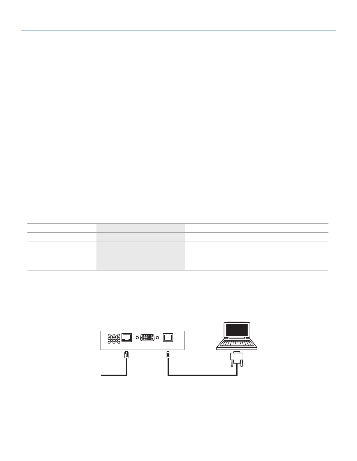
2. Tuning: In order to achieve the best possible picture quality, you must tune the system. You can tune the system from the
Transmitter position or from the Receiver itself. By tuning from the Receiver, you have the advantage of being able to see the
tuning, right on the screen. To tune from the Broadcaster position, please see the Transmitter‘s user guide; to tune from the
Receiver‘s position, connect the Serial Download cable to the Receiver Tuning Port and the Serial port of a computer that
carries the Service Utility. See Figure 1 below.
To computer‘s Serial port
To Transmitter Tuning from the Receiver Tuning Port
Page 2
Figure 1: The proper connection for tuning the system from a computer that has the Service Utility software.
724-746-5500 | blackbox.com
AC3003A-NEC
Page 3

HD View – NEC-Integrated Receivers
Troubleshooting
1. If the green LED is not on:
a. Is the receiver correctly positioned in the slot? Are the screws tightened?
b. Is the display turned on?
2. If the LED is on, but there is no picture:
a. Have you selected "Option" as input?
b. Although it is unlikely, please check to see if the dip switches in the back of the unit (behind the black 60-pin connector) are
in the correct position. The dipswitches on the unit must be set as follows:
Position 1 2 3 4
State Off Off On On
3. If the picture is out of focus:
a. Has the correct resolution been set?
- NEC MultiSync® LCD4020, LCD4620: 1360 x 768
- NEC M40, M46 and MultiSync LDC5220, LCD6520, L&P: 1920 x 1080
b. The display has possibly been set up for a different size. Press the “Size“ button on the remote control until “standard“ is
displayed in green in the top right-hand side of the screen.
c. Has the unit been tuned properly? [See “Operating and Maintaining Instructions / Tuning]
AC3003A-NEC
Page 3
Page 4

© Copyright 2010. Black Box Corporation. All rights reserved. Printed in U.S.A. Black Box® and the Double Diamond logo are registered trademarks of BB Technologies, Inc. Double Diamond™
and HD View™ are trademarks of BB Technologies, Inc. Any third-party trademarks appearing in this publication are acknowledged to be the property of their respective owners.
AC3003A-NEC, rev. 1
FREE, live, 24/7 Tech Support is just 30 seconds away.
724-746-5500 | blackbox.com
 Loading...