

Page 1

1000 Park Drive • Lawrence, PA 15055-1018 • 724-746-5500 • Fax 724-746-0746
© Copyright 2007. Black Box Corporation. All rights reserved.
Page 2
Order toll-free in the U.S.: Call 877-877-BBOX (outside U.S. call 724-746-5500)
FREE technical support 24 hours a day, 7 days a week: Call 724-746-5500 or fax 724-746-0746
Mailing address: Black Box Corporation, 1000 Park Drive, Lawrence, PA 15055-1018
Web site: www.blackbox.com • E-mail: info@blackbox.com
CUSTOMER
SUPPORT
INFORMATION
FEBRUARY 2007
AC1059A
AC1059A-E
Remote Video System IP
Page 3

Page 4

FCC AND IC RFI STATEMENTS
1
FEDERAL COMMUNICATIONS COMMISSION
and INDUSTRY CANADA
RADIO FREQUENCY INTERFERENCE STATEMENTS
Class B Digital Device. This equipment has been tested and found to comply with the limits for a Class B
computing device pursuant to Part 15 of the FCC Rules. These limits are designed to provide reasonable
protection against harmful interference in a residential installation. However, there is no guarantee that
interference will not occur in a particular installation. This equipment generates, uses, and can radiate radio
frequency energy, and, if not installed and used in accordance with the instructions, may cause harmful
interference to radio communications. If this equipment does cause harmful interference to radio or
telephone reception, which can be determined by turning the equipment off and on, the user is encouraged to
try to correct the interference by one of the following measures:
• Reorient or relocate the receiving antenna.
• Increase the separation between the equipment and receiver.
• Connect the equipment into an outlet on a circuit different from that to which the receiver is connected.
• Consult an experienced radio/TV technician for help.
CAUTION:
Changes or modifications not expressly approved by the party responsible for
compliance could void the user’s authority to operate the equipment.
To meet FCC requirements, shielded cables and power cords are required to connect this device to a personal
computer or other Class B certified device.
This digital apparatus does not exceed the Class B limits for radio noise emission from digital apparatus set out in the Radio
Interference Regulation of Industry Canada.
Le présent appareil numérique n’émet pas de bruits radioélectriques dépassant les limites applicables aux appareils numériques
de classe B prescrites dans le Règlement sur le brouillage radioélectrique publié par Industrie Canada.
EUROPEAN UNION DECLARATION OF CONFORMITY
This equipment complies with the requirements of the European EMC Directive 89/336/EEC.
Page 5

REMOTE VIDEO SYSTEM IP
2
NORMAS OFICIALES MEXICANAS (NOM)
ELECTRICAL SAFETY STATEMENT
INSTRUCCIONES DE SEGURIDAD
1. Todas las instrucciones de seguridad y operación deberán ser leídas antes de que el aparato eléctrico sea
operado.
2. Las instrucciones de seguridad y operación deberán ser guardadas para referencia futura.
3. Todas las advertencias en el aparato eléctrico y en sus instrucciones de operación deben ser respetadas.
4. Todas las instrucciones de operación y uso deben ser seguidas.
5. El aparato eléctrico no deberá ser usado cerca del agua—por ejemplo, cerca de la tina de baño, lavabo,
sótano mojado o cerca de una alberca, etc..
6. El aparato eléctrico debe ser usado únicamente con carritos o pedestales que sean recomendados por el
fabricante.
7. El aparato eléctrico debe ser montado a la pared o al techo sólo como sea recomendado por el fabricante.
8. Servicio—El usuario no debe intentar dar servicio al equipo eléctrico más allá a lo descrito en las
instrucciones de operación. Todo otro servicio deberá ser referido a personal de servicio calificado.
9. El aparato eléctrico debe ser situado de tal manera que su posición no interfiera su uso. La colocación del
aparato eléctrico sobre una cama, sofá, alfombra o superficie similar puede bloquea la ventilación, no se
debe colocar en libreros o gabinetes que impidan el flujo de aire por los orificios de ventilación.
10. El equipo eléctrico deber ser situado fuera del alcance de fuentes de calor como radiadores, registros de
calor, estufas u otros aparatos (incluyendo amplificadores) que producen calor.
11. El aparato eléctrico deberá ser connectado a una fuente de poder sólo del tipo descrito en el instructivo
de operación, o como se indique en el aparato.
12. Precaución debe ser tomada de tal manera que la tierra fisica y la polarización del equipo no sea
eliminada.
13. Los cables de la fuente de poder deben ser guiados de tal manera que no sean pisados ni pellizcados por
objetos colocados sobre o contra ellos, poniendo particular atención a los contactos y receptáculos donde
salen del aparato.
14. El equipo eléctrico debe ser limpiado únicamente de acuerdo a las recomendaciones del fabricante.
15. En caso de existir, una antena externa deberá ser localizada lejos de las lineas de energia.
16. El cable de corriente deberá ser desconectado del cuando el equipo no sea usado por un largo periodo de
tiempo.
17. Cuidado debe ser tomado de tal manera que objectos liquidos no sean derramados sobre la cubierta u
orificios de ventilación.
Page 6

NOM STATEMENT
3
18. Servicio por personal calificado deberá ser provisto cuando:
A: El cable de poder o el contacto ha sido dañado; u
B: Objectos han caído o líquido ha sido derramado dentro del aparato; o
C: El aparato ha sido expuesto a la lluvia; o
D: El aparato parece no operar normalmente o muestra un cambio en su desempeño; o
E: El aparato ha sido tirado o su cubierta ha sido dañada.
Page 7

REMOTE VIDEO SYSTEM IP
4
TRADEMARKS USED IN THIS MANUAL
Macintosh is a registered trademark of Apple Computer, Inc.
BLACK BOX and the Double Diamond logo are registered trademarks of BB Technologies, Inc.
IBM is a registered trademark of International Business Machines Corporation.
Linux is a registered trademark of Linus Torvalds.
Microsoft, MS-DOS, and Windows are either trademarks or registered trademarks of Microsoft Corporation in
the United States and/or other countries.
Java is a trademark of Sun Microsystems, Inc.
Telnet is a trademark of Telnet Communications, Inc.
UL is a registered trademark of Underwriters Laboratories Inc.
UNIX is a registered trademark of UNIX System Laboratories, Inc.
Any other trademarks mentioned in this manual are acknowledged to be the property of the trademark owners.
Page 8

IMPORTANT SAFETY INFORMATION
5
Important Safety Information
This device complies with the safety requirements standards listed below:
•UL
®
1950, third edition
• CSA No. 950
Take the following precautions to avoid contact with electrical current:
• Never install electrical wiring during an electrical storm.
• Never install an Ethernet connection in wet locations unless the product is specifically designed for wet
locations.
• Use caution when installing or modifying Ethernet lines.
• Make sure the tools you use (such as a screwdriver) have insulated handles.
• Wear safety glasses or goggles.
• Do not place Ethernet wiring or connections in any conduit, outlet, or junction box containing electrical
wiring.
• Installing inside wire may bring you close to electrical wire, conduit, terminals, and other electrical facilities.
Use extreme caution to avoid electrical shock from such facilities, and avoid contact with all such facilities.
• Install Ethernet wiring at least 6 feet (1.8 m) from bare power wiring or lightning rods and associated wires,
and at least 6 inches (15.2 cm) from other wire (antenna wires, doorbell wires, wires from transformers to
neon signs, etc.), steam or hot water pipes, and heating ducts.
• Do not use an Ethernet device while in a bathtub, shower, swimming pool, or similar hazardous location.
• Do not connect to, remove, or modify protectors and grounding wire placed by the service provider.
• Do not touch uninsulated Ethernet wiring if lightning is likely.
• External wiring: Any external communications wiring you may install needs to be constructed to all relevant
electrical codes. In the United States, this is the National Electrical Code Article 800. Contact a licensed
electrician for details.
Page 9

REMOTE VIDEO SYSTEM IP
6
Contents
Chapter Page
1. Specifications .........................................................................................................................................................8
2. Overview .................................................................................................................................................................9
2.1 Introduction.................................................................................................................................................9
2.2 What’s Included.........................................................................................................................................10
2.3 Hardware Description ...............................................................................................................................10
2.3.1 Front Panel ...................................................................................................................................10
2.3.2 Back Panel ....................................................................................................................................12
2.4 Remote Video System IP Configuration Examples.................................................................................12
2.4.1 Point-of-Sale Stations ...................................................................................................................13
2.4.2 Restaurant Ordering Stations......................................................................................................14
2.4.3 Other Industry Applications........................................................................................................16
3. Hardware Installation ..........................................................................................................................................17
4. Configuring Devices ............................................................................................................................................18
4.1 Assign an IP Address to the Device ..........................................................................................................18
4.1.1 Configuring the IP Address Using the RVS Device Setup Wizard ...........................................18
4.1.2 Configuring the IP Address Using DHCP..................................................................................19
4.1.3 Configuring the IP Address Using Auto-IP ................................................................................19
4.1.4 Testing the IP Address Configuration ........................................................................................19
4.2 Configuration Through the RVS Device Setup Wizard..........................................................................20
4.2.1 Discover the Device......................................................................................................................21
4.2.2 Configure Network Settings ........................................................................................................22
4.2.3 Configure Remote Video System IP Settings ............................................................................23
4.2.4 Install RealPort and Specify a Device Description.....................................................................29
4.2.5 Verify Configuration Settings......................................................................................................30
4.2.6 Save Settings .................................................................................................................................31
4.2.7 Completing the Wizard................................................................................................................32
4.2.8 To Further Configure the Remote Video System IP..................................................................32
4.3 Configuration Through the Web User Interface....................................................................................33
4.3.1 Open the Web Interface..............................................................................................................33
4.3.2 Organization of the Web Interface.............................................................................................35
4.3.3 Change the IP Address ................................................................................................................36
4.3.4 Configure Terminal Emulator Settings ......................................................................................37
4.3.5 Configure Remote Access Settings .............................................................................................40
4.3.6 Configure Video Settings.............................................................................................................42
4.3.7 Configure Network Communications ........................................................................................43
4.3.8 Configure Serial Ports..................................................................................................................45
4.3.9 Configure System Settings...........................................................................................................47
4.3.10 Configure Security Features........................................................................................................48
Page 10

CONTENTS
7
Chapter Page
4.4 Configuration Through the Command Line ..........................................................................................48
4.4.1 Accessing the Command Line ....................................................................................................48
4.4.2 Verifying Which Commands are Supported..............................................................................48
4.5 Batch Capabilities for Configuring Multiple Devices .............................................................................49
5. Monitoring Devices..............................................................................................................................................50
5.1 About Monitoring......................................................................................................................................50
5.2 Monitoring Capabilities from the Web User Interface...........................................................................50
5.3 Monitoring Capabilities from SNMP .......................................................................................................57
5.4 Monitoring Devices from the Command Line........................................................................................57
6. Administering Devices .........................................................................................................................................59
6.1 Administration from the Web User Interface .........................................................................................59
6.1.1 File Management..........................................................................................................................59
6.1.2 Backup/Restore Device Configurations.....................................................................................60
6.1.3 Update Firmware and Boot/POST Code...................................................................................61
6.1.4 Restore Device Configuration to Factory Defaults ....................................................................62
6.1.5 Display System Information.........................................................................................................64
6.1.6 Reboot the Device........................................................................................................................65
6.2 Administration from the Command-Line Interface ...............................................................................66
7. Troubleshooting...................................................................................................................................................67
7.1 Calling Black Box.......................................................................................................................................67
7.2 Shipping and Packaging ...........................................................................................................................67
Page 11

REMOTE VIDEO SYSTEM IP
8
1. Specifications
Serial Inter
face
Flow Control: Hardware and software
Signal Support: Serial port 1: Full signal support for TXD, RXD, RTS, CTS, DTR, DSR, and DCD;
Serial port 2: Signal support for TXD, RXD, RTS, and CTS only
Interface: Serial ports 1 and 2: EIA-232 (DB9 male, 5, 6, 7, or 8 data bits, 1, 1.5, or 2 stop bits,
mark/space/even/odd parity)
Network Inter
face
Standard: IEEE 802.3af
Physical Layer: 10/100BASE-T
Data Rate: 100 Mbps, autosensing
Recommended Network Use Rate: Below 50%
Ethernet Duplex Mode: Full duplex, half-duplex, autosensing
General
Resolution: Up to 1600 x 1200, up to 32-bit color
Performance: Near-motion video
Operating Systems Supported: Compatible with any operating system supporting VNS server application,
including Windows
®
, Linux®, and other UNIX®platforms; Macintosh®; and DOS (no RealPort support)
Network Compatibility: 10-/100-Mbps switched Ethernet
Memory: 16 MB RAM
Throughput Speed: Up to 230,400 bps
User Controls: (1) Reset pushbutton
Connectors: Ethernet: (1) 10/100 RJ-45;
Video: (1) HD15 F;
USB: (2) Type A F;
Serial: (1) RS-232 DB9 male, (1) RS-232 RJ-45;
Audio: (1)
1
⁄8
" stereo headphone (unamplified) output jack, (1)
1
⁄8
" mono microphone input jack,
(1) 4-section speaker connector (not used);
Power: (1) barrel connector
Indicators: (5) LEDs: (1) System Status, (1) USB Port 1, (1) USB Port 2, (1) Ethernet Port Link Status,
(1) Ethernet Port Activity Status
Temperature Tolerance: 32 to 131°F (0 to 55°C)
Relative Humidity: Up to 95%, noncondensing
Power: AC1059A: 115 VAC, 60 Hz, external; AC1059A-E: 230 VAC, 50 Hz, external
Size: 1"H x 7.2"W x 4.4"D (2.5 x 18.3 x 11.2 cm)
Weight: 0.6 lb. (0.3 kg)
Page 12

9
2. Overview
2.1 Introduction
With the Remote Video System IP (RVS), you can place one or more video displays at remote locations and
control the displays from a centrally-located CPU. For example, in a retail environment, you might have an RVS
at each cash register (or user station) connected via a network to the CPU. At each user station, you will need
one RVS. Each RVS has one VGA or SVGA port (links to a video-display monitor) and two USB ports (connect
to individual USB devices, such as a keyboard, mouse, or touch panel). If you need to connect more than two
USB devices to the RVS at the user station, you can plug a multiple-port USB hub into one or both of the RVS’s
USB ports. You can link multiple RVSes to one CPU.
The RVS connects to a Ethernet network. One RJ-45 Ethernet connector and two serial port connectors (one
DB9 and one RJ-45 connector) are on the RVS’s back panel to use for these connections. You can use one, two,
or all three ports at a user station.
Because it uses Display Over IP technology, this network-enabled video display hub makes it easy to connect
video displays anywhere on a wired LAN, while eliminating the need for locally-attached host PCs. It provides
one VGA or SVGA video port and multiple serial and USB ports for human interface devices such as a
keyboard, mouse, or touch panel. The Remote Video System IP software enables remote displays to
communicate with the host PC, without changing existing application software. Remote displays can be
centrally managed and monitored from a remote server or PC via an IP address.
The Remote Video System IP uses VNC (Virtual Network Computing) client software to provide remote access
to a computer on the network or Internet. This allows the device to communicate with the host PC without
changing existing application software. You must install VNC server or VNC client software on the host PC.
Centrally monitor and manage airport status displays or stadium scoreboards, for example, from a remote
server or PC via an IP address. For details about VNC software (included on the software and documentation
CD-ROM), see Section 4.3.5. To assign an IP address, see Section 4.1.
Remote Video System IP uses the patented RealPort COM/TTY port redirection for Microsoft
®
Windows,
UNIX, and Linux environments. RealPort software provides a virtual connection to serial devices, no matter
where they reside on the network. The software is installed directly on the host PC and allows applications to
talk to devices across a network as though the devices were directly attached to the host. Actually, the devices
are connected to a RVS device somewhere on the network. The RealPort driver (included on the CD-ROM)
translates serial over IP.
For legacy terminal-based systems, the Remote Video System IP also supports standard terminal emulation. You
can use the Remote Video System IP today in a terminal-oriented configuration and migrate to newer graphic
displays whenever you want.
Configure the Remote Video System IP for terminal emulation or remote access via a setup wizard. To further
fine-tune the configuration settings, monitor performance, and perform administration tasks, use the RVS’s
Web user interface, command-line interface, or Simple Network Management Protocol (SNMP) interface.
For security, the RVS uses one password and one permission level. It also features encryption and SNMP
security.
CHAPTER 2: Overview
Page 13
REMOTE VIDEO SYSTEM IP
10
2.2 What’s Included
Your package should include the following items. If anything is missing or damaged, please contact Black Box
Technical Support.
• Remote Video System IP
• Software and documentation CD-ROM
• Terminal block
• AC power supply
2.3 Hardware Description
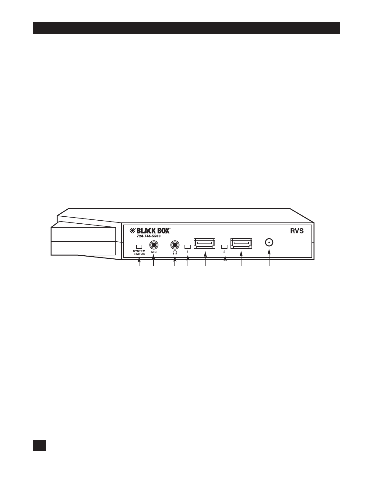
2.3.1 FRONT PANEL
The Remote Video System IP’s front panel is shown in Figure 2-1. Its numbered components are described in
Table 2-1.
Figure 2-1. Front panel.
➀➁
➄➄
➂➃
➅➆
Page 14

CHAPTER 2: Overview
11
Table 2-1. Front-panel indicators, connectors, and user controls.
Number Component Color Description
➀ System Status LED Solid red Hardware is initializing.
1-1-1 blinking green Firmware is initializing.
1-5-1 blinking green Device configuration has been restored to
its factory defaults.
Other blinking green Contact Tech Support.
➁
1
⁄8" connector — Used for mono microphone input.
➂
1
⁄8" connector — Used for stereo headphone output (unamplified).
➃ USB Port 1 Status LED Solid red Hardware is initializing.
Solid green Port is powered on and ready for operation.
➄ (2) USB Type A ports — Add up to two USB devices (keyboard, mouse,
touch panel, etc.) at the point of display. To add
more than two USB devices, connect a multipleport USB hub to one or both of these ports.
➅ USB Port 2 Status LED Solid red Hardware is initializing.
Solid green Port is powered on and ready for operation.
➆ Reset button — Press and hold this button to reset the RVS.
Page 15
REMOTE VIDEO SYSTEM IP
12
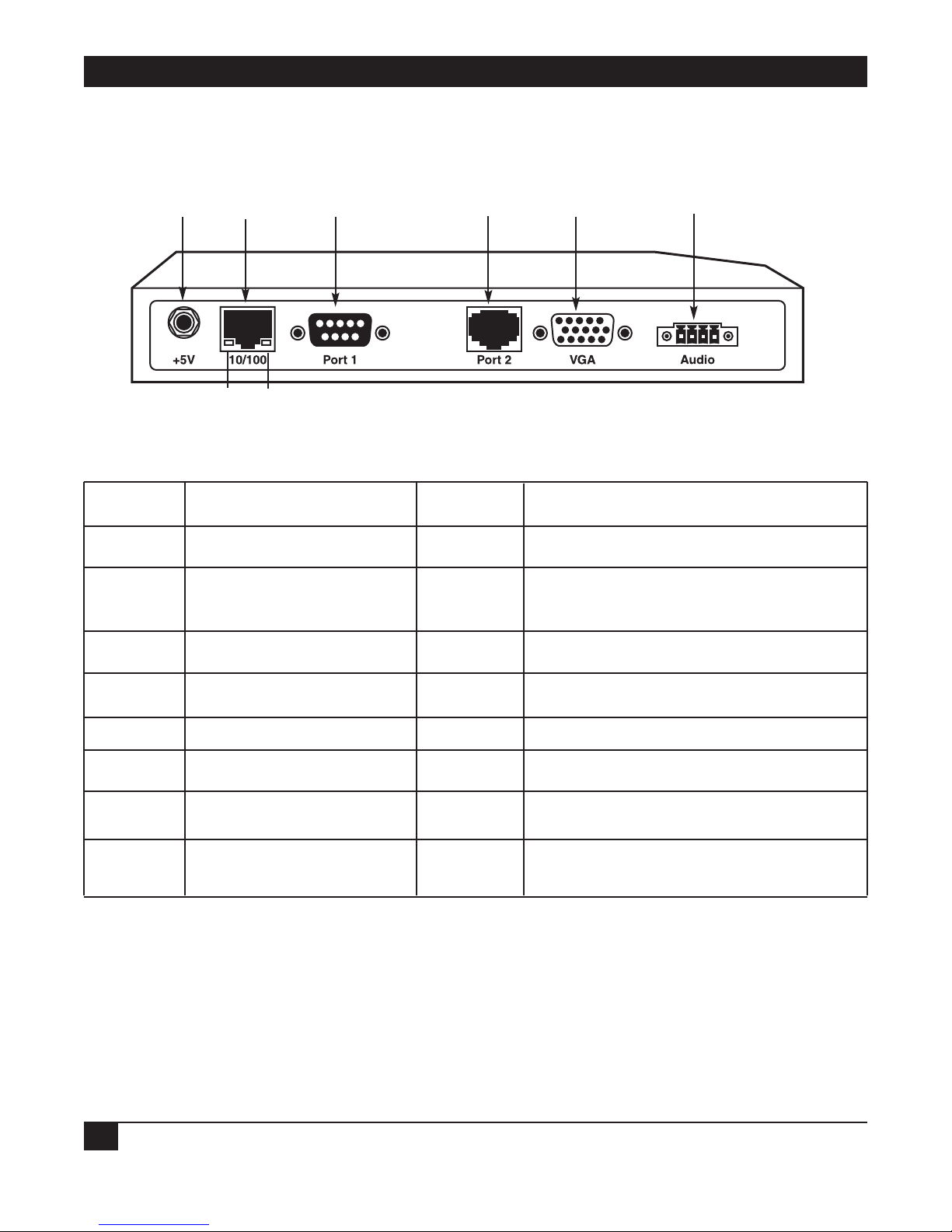
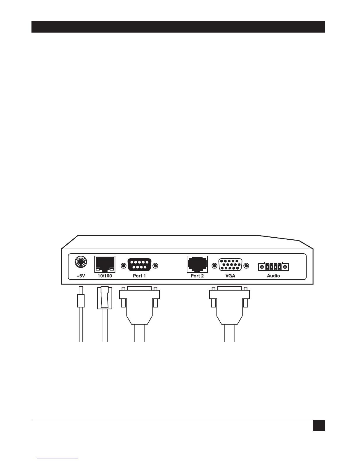
2.3.2 BACK PANEL
The Remote Video System IP’s back panel is shown in Figure 2-2. Its labeled components are described in Table
2-2.
Figure 2-2. Back panel.
Table 2-2. Back-panel indicators, connectors, and user controls.
Number Component Color Description
➀ +5V power connector — Plug the power cord into this connector.
➁ 10/100 RJ-45 port — Use this connector for an Ethernet
connection.
➂ Ethernet Port Link Status LED Solid green Ethernet link is up.
➃ Ethernet Port Activity Status LED Blinking yellow Ethernet traffic is on the link.
➄ DB9 Port 1 — Use this connector for a serial connection.
➅ RJ-45 Port 2 — Use this connector for a serial connection.
➆ VGA connector — Connect the monitor here.
➇ Speaker connector — This connector is not currently supported.
It’s reserved for future use.
2.4 Remote Video System IP Configuration Examples
Protect your CPU from extreme temperatures and humidity. For example, you can have an RVS connected to a
VGA display monitor, USB mouse, and USB keyboard at an outdoor display booth. Since the CPU links to the
network via an IP connection, you can place it indoors in a temperature- and humidity-controlled environment.
Plus, relocating the PC CPU to a back office or other remote location lets you manage a multiple-RVS network
via a single IP connection.
➀➁ ➅➄➆
➇
➂
➃
Page 16
CHAPTER 2: Overview
13
Sections 2.4.1 through 2.4.3 describe possible RVS applications.
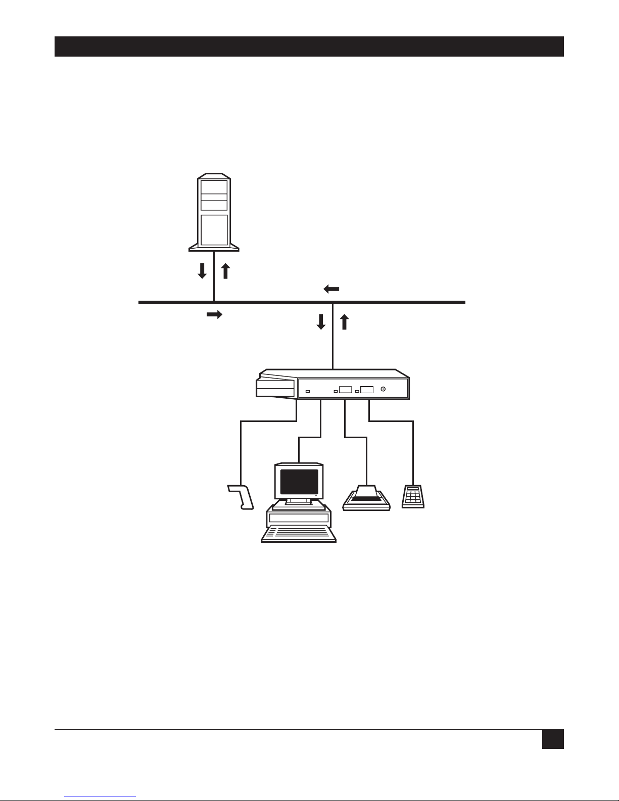
2.4.1 P
OINT
-OF-SALE STATIONS
This example shows Remote Video System IP in use in a point-of-sale station in a department store. The
Remote Video System IP allows the business to remove PCs from the point-of-sale stations and have them in the
back office instead.
Figure 2-3. Point-of-sale application.
With the RealPort and VNC drivers on the server, the Remote Video System IP allows for USB, serial, or VGA
data and control to be transmitted over the network. The USB, serial, and VGA protocols are encapsulated in
IP packets that are transmitted. The Remote Video System IP is compatible with standard VGA or SVGA
displays and can also be used with an AnywhereUSB network-enabled USB hub to add additional USB devices
such as a keyboard and a mouse at the point of display.
NOTE
Right now, only USB devices that do not require drivers are supported at the point of
display. However, future releases of the Remote Video System IP will support USB
connections to a wider range of devices.
Server
USB, serial, or VGA
USB, serial, or VGA
TCP/IP 10/100 Ethernet
Ethernet LAN
USB
VGA Serial
Serial
Bar-code
scanner
Receipt
printer
Credit card
reader
Alphanumeric
cash register
Remote Video System IP
(AC1059A)
RealPort, VNC
software drivers
Page 17
REMOTE VIDEO SYSTEM IP
14
2.4.2 RESTAURANT ORDERING STATIONS
Use the Remote Video System IP for terminal emulation at restaurant ordering stations.
Serial Configuration
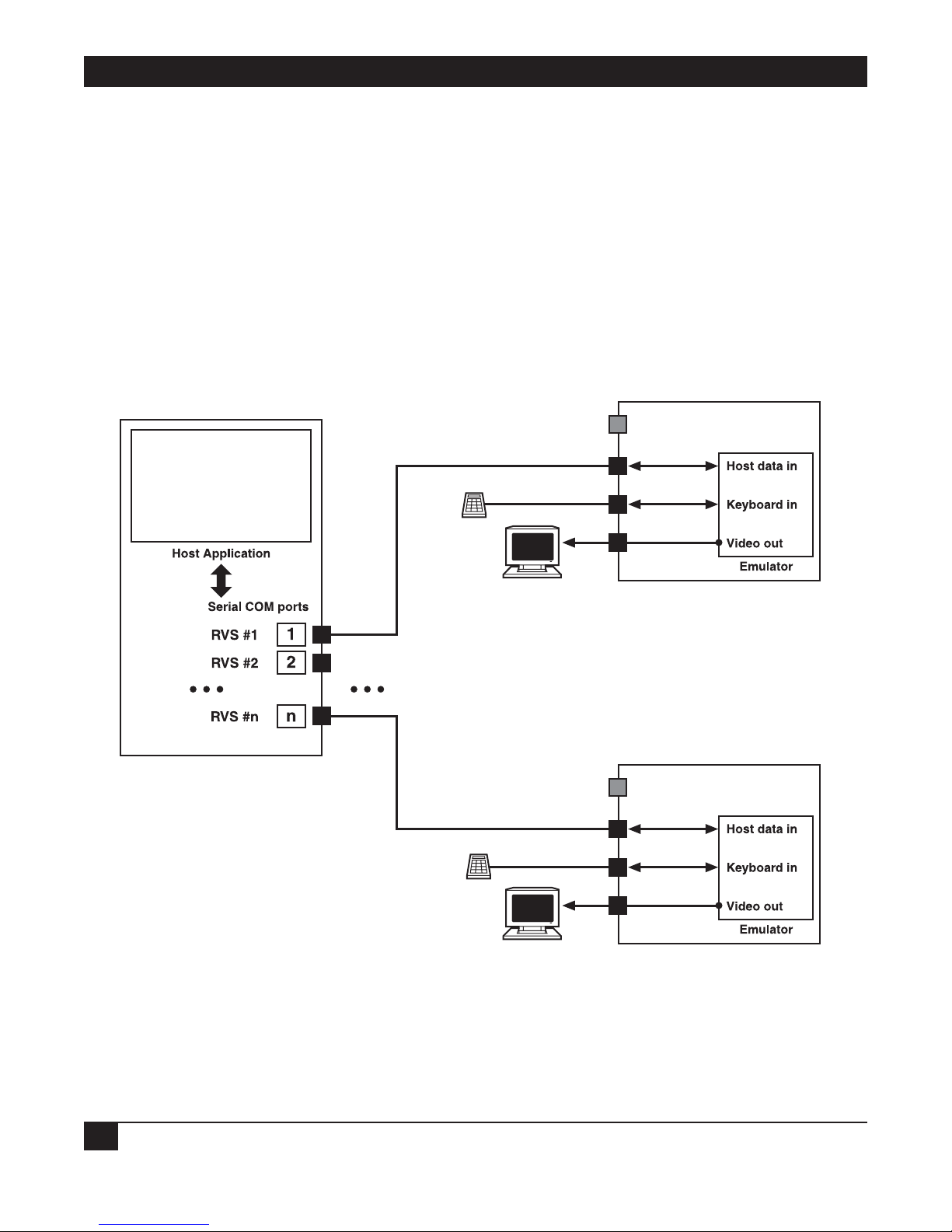
Figure 2-4 shows the Remote Video System IP in a serial configuration. In this example, the Remote Video
System IP serves as a drop-in replacement for an existing kitchen display terminal. This configuration consists
of the application server driving the remote displays through a serial connection. The display data is sent in the
VT200 data stream format. Remote Video System IP receives the display data, interprets the protocol, and sends
the output to the attached display. A serial bump bar (a water-resistant keyboard commonly used in restaurants)
or other keyboard device may be connected to the Remote Video System IP. Data received from this bump bar
will be relayed back to the server application over the host connection serial line. The Remote Video System IP
can be configured to perform simple bump bar key data remapping.
Figure 2-4. Restaurant ordering station application, serial configuration.
Application server
Kitchen station
Kitchen station
Remote Video System IP #1
Remote Video System IP #n
Serial ports
Serial ports
Serial ports
Ethernet
Ethernet
Bump bar
Bump bar
Monitor
VGA
VGA
Monitor
Page 18
CHAPTER 2: Overview
15
Ethernet Configuration
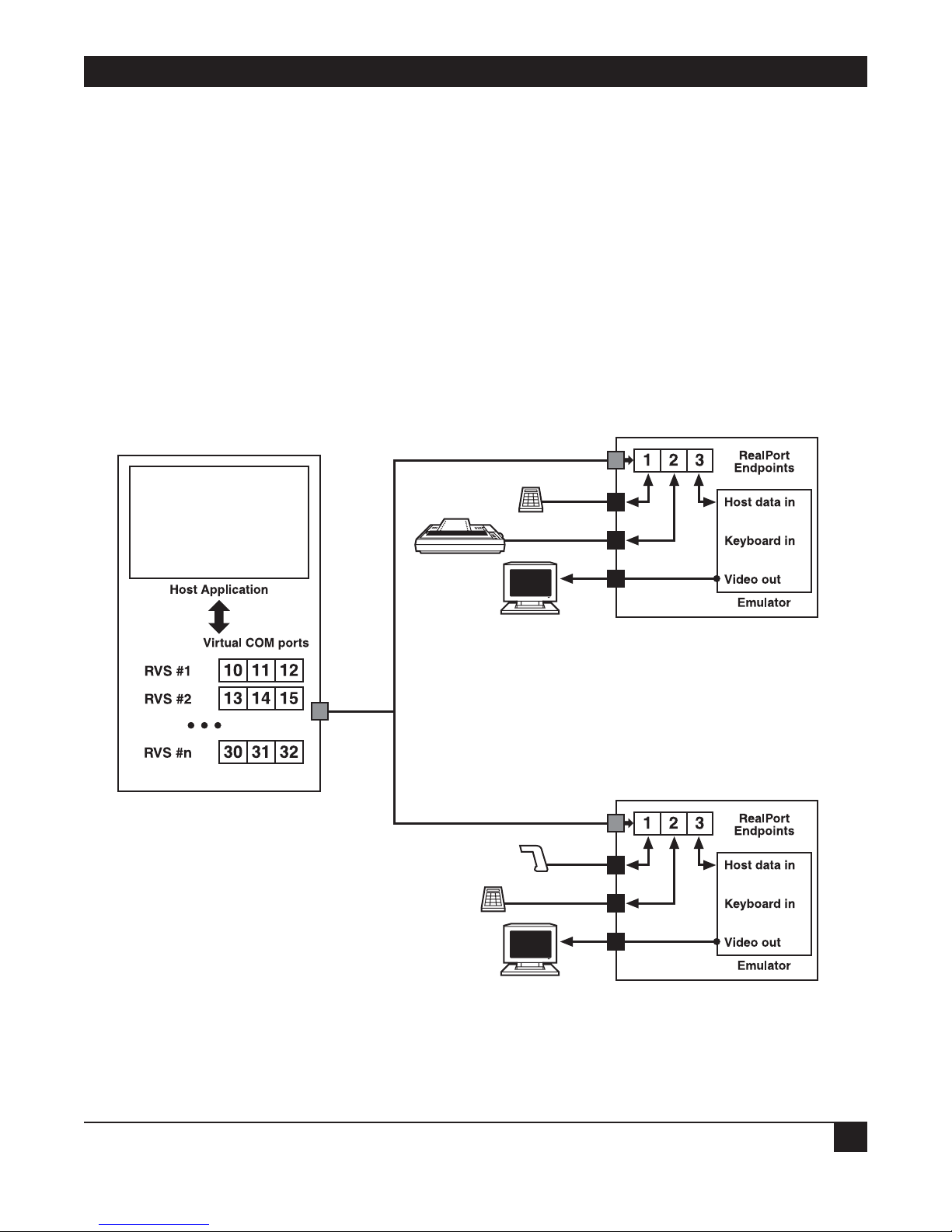
Figure 2-5 shows Remote Video System IP in an Ethernet configuration.
In this environment, the server application drives the remote displays through an Ethernet connection. The
display data is sent in the VT200 data stream format. Instead of communicating with a serial communications
port, the server application now communicates with a virtual communications port—both of these ports appear
identical to the server application so no modifications are required to the server application. The virtual COM
port transports the display data over the Ethernet to the destination Remote Video System IP where it is
received, interpreted, and rendered to the attached VGA display. As in the first configuration, you can attach a
local bump bar or other keyboard device to the Remote Video System IP if desired. In this configuration, one
or both of the serial ports on the Remote Video System IP are now available for use as serial ports. You can map
those serial ports to additional virtual communications ports on the server for the application’s use. The
Remote Video System IP appears to have three serial ports. Actually, there are two native serial ports (serial port
1 and serial port 2) and one VGA/video port.
Figure 2-5. Restaurant ordering station application, Ethernet configuration.
Ethernet
Ethernet
Operator station
Keypad
Receipt
printer
Monitor
Serial ports
VGA
Remote Video System IP Display #1
Remote Video System IP Display #n
Ethernet
Car hop station
Scanner
Bump bar
Monitor
Serial ports
VGA
Page 19

REMOTE VIDEO SYSTEM IP
16
2.4.3 OTHER INDUSTRY APPLICATIONS
Other applications for the Remote Video System IP include:
• Banking: Place teller display stations in the bank’s customer area, and secure the server driving the teller
stations in a back office.
• Elevators: Elevator stations in luxury condominiums, hotels, and office buildings display advertising,
building information, and include a touch panel. These stations usually have a PC in each elevator car. Use
an RVS in each elevator car, and control the elevator displays from a central PC. The Remote Video System
IPs are linked to the PC by Ethernet cables in the elevator car’s wiring system.
• Industrial Automation: Remote Video System IP provides a solution for areas that don’t have a PC but need
a display and data-entry user station. Examples include clean-room environments, heavy-equipment
environments, or environments with chemicals in the atmosphere.
• Automobile dealerships: An automobile dealership’s service department can have rugged display stations
suited to the environment, and keep the PC in an office.
• Airports/airlines: Use the Remote Video System IP for flight-status display stations. Instead of installing a
PC for every display station, the PC that gathers and displays flight data can be in a central site. The display
stations instead have Remote Video System IPs that handle, receive, and display the flight data from the
central PC.
Page 20
CHAPTER 3: Hardware Installation
17
3. Hardware Installation
Your package should include the items listed in Section 2.2. You will also need an Ethernet cable, a serial cable,
and a VGA cable.
First, you will install the necessary cables and power supply. Then, refer to Chapter 4 to install and configure
the Remote Video System IP’s software.
1. Connect the Ethernet cable to the 10/100 RJ-45 port on the Remote Video System IP’s back panel (see
Figure 2-2).
2. Connect the serial device’s cable to either the DB9 male Port 1 connector or the RJ-45 Port 2 connector.
3. Link the display device (monitor) cable to the VGA connector on the RVS’s back panel.
4. Connect the power supply to the back-panel power connector.
5. Plug the power supply into an AC power outlet.
NOTE
The 4-section speaker connector is not supported. It’s reserved for future use.
The next step is to install the software, as described in Chapter 4.
Figure 3-1. Hardware connections.
Connect
power supply
Connect
Ethernet
Connect
serial
device
Connect
display
device
4-section
speaker
connector
(not used)
Page 21

REMOTE VIDEO SYSTEM IP
18
4. Configuring Devices
To install and configure the RVS’s software, you will first need to assign an IP address to the device (see Section
4.1). Then configure the RVS in one of three ways: via the Setup Wizard (Section 4.2), the Web user interface
(Section 4.3), or the Command-Line Interface (Section 4.4). You can also configure multiple devices via batch
configuration (Section 4.5).
4.1 Assign an IP Address to the Device
4.1.1 CONFIGURING THE
IP ADDRESS USING THE RVS DEVICE SETUP WIZARD
The preferred way to assign an IP address and initially configure the RVS is to use the RVS Device Setup
Wizard. This software is on the CD that you received with your Remote Video System IP.
The RVS Device Setup Wizard “discovers” the device, and then assigns an IP address and configures your device
for your needs. It can be used with the Web interface to “tweak” the specific environment. This quick,
automated, and complete setup is specially designed for the Windows environments.
Prerequisites
Make sure your installation meets the following requirements:
• Connect the Remote Video System IP to the network and power it up.
• Use the CD on a system running a Microsoft Windows or UNIX operating system.
• Write down the MAC address for the Remote Video System IP (located on the label on the bottom of the
product) and record it to use later to assign an IP address.
Procedure
1. Insert the RVS CD in the CD drive. If the CD does not start automatically, double-click
My Computer > CD ROM Drive > setup.exe.
2. The RVS Device Setup Wizard will automatically pop up. Select your platform and click Next. The RVS
device discovery utility finds and lists all RVS devices on your network.
3. Locate your Remote Video System IP by its MAC address.
4. Select the Remote Video System IP and then click Next.
Follow the instructions in the wizard to configure your Remote Video System IP. Use the online help supplied
with the wizard if you need more information about values the wizard prompts you to supply and select.
Page 22

19
CHAPTER 4: Configuring Devices
4.1.2 CONFIGURING THE IP ADDRESS USING DHCP
You can also configure an IP address using DHCP.
Prerequisite
Make sure your installation meets the following requirements:
• Configure the Remote Video System IP as a DHCP client. Since this is the default configuration, this will be
the case unless you’ve changed the configuration.
• Power off the Remote Video System IP.
Procedure
1. Set up a permanent entry for the Remote Video System IP on a DHCP server.
2. Connect the Remote Video System IP to the network and power it on. The IP address configured in step 1
is assigned automatically.
4.1.3 C
ONFIGURING THE IP ADDRESS USING AUTO-IP
The standard protocol Automatic Private IP Addressing (APIPA or Auto-IP) assigns the IP address from the
reserved IP addresses in Auto-IP. Use ADDP or DHCP to find the device and assign it a new IP address that is
compatible with your network. Once the unit is plugged in, Auto-IP automatically assigns the IP address.
4.1.4 T
ESTING THE IP ADDRESS CONFIGURATION
Once the IP address is assigned, test the IP address configuration to make sure it works as configured.
Prerequisite
Configure the Remote Video System IP with an IP address.
Procedure
1. Access the command line of a PC or other networked device.
2. Type in the following command:
ping ip-address
where ip-address is the address you assigned to the Remote Video System IP.
Example
ping 192.168.2.2
The device returns a reply. The IP address displays on the screen briefly while the Remote Video System IP
powers on.
Page 23

REMOTE VIDEO SYSTEM IP
20
4.2 Configuration Through the RVS Device Setup Wizard
The RVS Device Setup Wizard discovers your Remote Video System IP on the network, configures basic network
settings, configures the Remote Video System IP for use as a terminal emulator or for remote access, and, as
needed, installs RealPort and VNC server software on your PC or server.
To run the RVS Device Setup Wizard, insert the software and documentation CD packaged with your Remote
Video System IP into your computer’s CD-ROM drive. The wizard’s first screen appears (see Figure 4-1). Click
Next.
Figure 4-1. RVS Device Setup Wizard welcome screen.
Page 24

21
CHAPTER 4: Configuring Devices
4.2.1 DISCOVER THE DEVICE
The RVS Device Setup Wizard’s Discover Device screen (see Figure 4-2) displays a list of RVS devices that the
wizard has discovered on the network. Double-click on the Remote Video System IP you want to configure, then
press Next.
Figure 4-2. Discover Device screen.
Page 25

REMOTE VIDEO SYSTEM IP
22
4.2.2 CONFIGURE NETWORK SETTINGS
On the Configure Network Settings screen (Figure 4-3), specify how the IP address settings are established for
your Remote Video System IP. To automatically obtain the IP settings, click on Obtain IP settings automatically
using DHCP. To manually enter the IP settings, type in the IP address, subnet mask, default gateway, DNS
server, domain, and host name, then click on Use the following IP settings and press Next.
Figure 4-3. Configure Network Settings screen.
Page 26

23
CHAPTER 4: Configuring Devices
4.2.3 CONFIGURE REMOTE VIDEO SYSTEM IP SETTINGS
From the drop-down Device Setup menu on the Configure RVS Display Settings screen (Figure 4-4), choose
whether you want to use the Remote Video System IP as a terminal emulator or for remote access. To use the
default configuration settings, check the box next to Use default configuration settings for this mode of
operation, then press Next.
Figure 4-4. Configure RVS Display Settings screen.
Page 27

REMOTE VIDEO SYSTEM IP
24
Configure Remote Video System IP for Terminal Emulation
To configure your Remote Video System IP for terminal emulation, use the default value Terminal Emulator in
the drop-down Device Setup menu (see Figure 4-5) for the Device Setup option, or specify your own settings.
The default settings are 9600 bits per second, 8 data bits, no parity, and 1 stop bit, with software flow control. To
use the default value, check the box next to Use default configuration settings for this mode of operation and
press Next.
Figure 4-5. Configure RVS for Terminal Emulation using default settings.
To use different settings from these defaults, uncheck the box next to Use default configuration settings for
this mode of operation. Press Next. Figure 4-6 appears.
Page 28

25
Figure 4-6. Configure RVS for Terminal Emulation screen using custom settings.
The Host Connection setting drop-down menu (options are either Serial Port 1 or Serial Port 2) can be seen in
Figure 4-6. From this menu, choose the serial port that you want to use for the host connection. You can set the
baud rate, data bits, parity, stop bits, and flow control settings for this port via the drop-down menus in Figure
4-6. Press Next.
When using a network connection, you must install the RealPort driver software on the host PC or server. This
will create a virtual COM port for each serial port on your Remote Video System IP (these are the traditional
RealPort COM ports) as well as one additional virtual COM port that can be used for the terminal emulator
connection. The host application must be configured to use this additional virtual COM port.
CHAPTER 4: Configuring Devices
Page 29

REMOTE VIDEO SYSTEM IP
26
Configure Serial Settings
When you press Next in Figure 4-6, the Configure Serial Settings screen appears (see Figure 4-7). On this
screen, using the drop-down menus, you can specify the communications parameters for the Host Connection
serial port that you selected in Figure 4-6. Drop-down menus include baud rate, data bits, parity, stop bits, and
flow control. Once you select the parameters, press Next.
Figure 4-7. Configure Serial Settings screen.
Fine-Tune Configuration As Needed Later
To further configure terminal emulation settings after the wizard completes its serial settings, use the Web user
interface’s Terminal Emulation page as described in Section 4.3.4.
Configure Remote Video System IP for Remote Access
Your Remote Video System IP can provide remote access to a computer on the network or Internet by using the
VNC (Virtual Network Computing) protocol. You can interact with the remote computer using a keyboard and
mouse connected to the USB ports on your Remote Video System IP.
When you press Next in Figure 4-7, Figure 4-8 appears.
Page 30

27
CHAPTER 4: Configuring Devices
To configure your Remote Video System IP for remote access (also known as a thin client configuration),
choose Remote Access from the Device Setup drop-down menu in Figure 4-8.
Figure 4-8. Configure the RVS for remote access.
Uncheck the box next to Use default configuration settings for this mode of operation, and several remote
access settings will appear. Check the box next to Install the VNC Server software. Select the location for the
software installation by clicking on the Browse button next to Location in Figure 4-8 and browsing through the
possible locations. Or, type in a location. Once you select the proper location, click Next.
Figure 4-9 appears.
Page 31

REMOTE VIDEO SYSTEM IP
28
Figure 4-9. Install the VNC Software screen.
Type in these settings as follows and check the box next to Install the VNC Server software:
• VNC server: Specify the IP address for the VNC server to connect to.
• Port: The network port number to connect to on the VNC server. The default network port number for
VNC servers is 5900.
• Password: The password for logging on to the VNC server.
• Install the VNC Server software: Specifies whether VNC server software should be installed on the host
computer and where it should be installed.
Once you type in these settings, press Next. Figure 4-10 appears.
About the VNC Server Software
The software and documentation CD that accompanies your Remote Video System IP includes a VNC server
that you can install. This VNC server is for Windows. If you want to connect to a Linux system, read the
documentation that accompanies your Linux distribution.
The VNC server provided with your Remote Video System IP is called UltraVNC. This VNC server installs a
special video driver (“mirror” driver) on your system; it provides superior performance on Windows 2000 and
XP systems.
Page 32

29
CHAPTER 4: Configuring Devices
If you already have another version of UltraVNC on your system, you need to uninstall it first and then reboot.
The reboot is critical to the server’s operation and performance.
After rebooting, install the UltraVNC from the software and documentation CD, then reboot again. Failure to
follow this sequence correctly can result in the driver not being installed properly and will affect performance.
While the VNC server will work, it will be slower.
After installation, the VNC server is enabled or disabled on the Web user interface’s Network Settings >
Network Services Settings page.
Fine-Tune Configuration As Needed Later
To further configure remote access settings after the wizard completes the RVS Display settings, use the Web
user interface’s Remote Access Configuration page, as described in Section 4.3.5. You can also adjust the video
settings on the Video Configuration page, as described in Section 4.3.6.
4.2.4 I
NSTALL REALPORT AND SPECIFY A DEVICE DESCRIPTION
From the RVS Device Setup Wizard, you can install RealPort software from the CD-ROM on the computer you
are using to configure the Remote Video System IP. Specify a device description or useful name for the Remote
Video System IP.
Figure 4-10. Install RealPort software and describe a device.
Page 33

REMOTE VIDEO SYSTEM IP
30
Install RealPort Software
RealPort software must be installed and configured on each PC that will use the RealPort ports on the Remote
Video System IP. This RealPort software is available on the software and documentation CD. You can load it
from the RVS Device Setup Wizard. To install RealPort, check the box next to Install RVS RealPort on this
computer in Figure 4-10 and press Next.
Specify a Device Description
In the Device Description field, type in a name by which this Remote Video System IP will be known and
referred to. This Device Description can be particularly useful in installations where Remote Video System IP
devices are being used for multiple stations. For example, you could use the names “Operator 1,” “Operator 2,”
etc. or “Station 1,” “Station 2,” etc.
4.2.5 V
ERIFY CONFIGURATION SETTINGS
The Verify Configuration screen (Figure 4-11) shows the configuration settings that will be uploaded to your
Remote Video System IP when you click Next in Figure 4-10.
Figure 4-11. Checking configuration settings before uploading.
Once you check your configuration settings, press Next.
Page 34

31
CHAPTER 4: Configuring Devices
4.2.6 SAVE SETTINGS
When you click Next, the Save Settings page (Figure 4-12) is displayed while the configuration settings are
uploaded to the Remote Video System IP. Other messages and wizards may be displayed during this step. Click
OK on the message boxes and Next on the wizard screens to continue the installation process.
Figure 4-12. Saving the configuration settings.
Page 35

REMOTE VIDEO SYSTEM IP
32
4.2.7 COMPLETING THE WIZARD
When the configuration settings have been uploaded to the Remote Video System IP, a finish screen appears
(Figure 4-13). There are several options for what to do next, including registering the Remote Video System IP
and opening other device interfaces to further configure the Remote Video System IP, such as the Web user
interface described in Section 4.3 or the command-line interface described in Section 4.4. You can also choose
to configure another Remote Video System IP using the RVS Device Setup Wizard. Click Finish to close the
wizard.
Figure 4-13. Finishing the Wizard setup.
4.2.8 T
O FURTHER CONFIGURE THE REMOTE VIDEO SYSTEM IP
Once a Remote Video System IP is configured through the RVS Device Setup Wizard, you can still view or
change any configuration values. Use either the Web user interface or the command-line interface to view and
change the configuration. See Sections 4.3 and 4.4 for more information.
Page 36

33
CHAPTER 4: Configuring Devices
4.3 Configuration Through the Web User Interface
This section describes using the Web user interface to configure your Remote Video System IP. We recommend
that you use this interface if the RVS Device Setup Wizard is unavailable, if your application requires specific
alterations not accessible on the Wizard, or if you wish to modify the device configuration from the values that
were setup through the RVS Device Setup Wizard.
4.3.1 O
PEN THE
WEB INTERFACE
To open the Web user interface, you can either type in the Remote Video System IP URL in a Web browser and
log on to the device, if required, or use the RVS Device Discovery utility to locate the RVS device and open its
Web interface.
By Entering the Device’s URL in a Web Browser
1. In the URL address bar of a Web browser, type in the device’s IP address.
2. If security has not been enabled for the RVS device, the Web user interface’s Home page appears. If
security has been enabled for the device, a login dialog displays. Type in the device’s user name and
password. If you do not know the user name and password for the device, contact the system administrator
who initially set up the device. The default username is “root” and the default password is “dbps.” Once
you type in the user name and password, the Web user interface’s Home page appears. See Section 4.3.2
for an overview of using the Home page and other linked pages.
By Using the RVS Device Discovery Utility
Use the RVS Device Discovery Utility as another option to locate your Remote Video System IP and open the
Web user interface.
Installing the RVS Device Discovery Utility
The RVS Device Discovery Utility is available on the software and documentation CD for your RVS. If this utility
is not already available on your computer, follow these steps.
1. On the main page of the software and documentation CD, click software—install optional software.
2. Select Device Discovery Utility and click Install.
3. Follow the prompts of the Setup Wizard to install the RVS Device Discovery Utility software.
Discovering a Device
1. From the start menu, select Start > Programs > RVS Connect > RVS Device Discovery. The RVS Device
Discovery application appears (see Figure 4-14).
Page 37

REMOTE VIDEO SYSTEM IP
34
2. Locate the device in the list of devices and double-click on it, or select the device from the list and select
Open web interface in the Device Tasks list.
Figure 4-14. Opening the Web interface.
3. By default, there is no password authentication enabled for Remote Video System IP. There is a single user,
named “root” with no password defined. The Web user interface opens and you can configure the device,
as described in Sections 4.3.4 through 4.3.10.
Page 38

35
CHAPTER 4: Configuring Devices
4.3.2 ORGANIZATION OF THE WEB INTERFACE
When you open the Web user interface, the Home page appears (see Figure 4-15).
Figure 4-15. The Web interface’s Home page.
The Home Page
The Home page’s left side has a menu for configuration, management, and administration tasks, and an option
to log out of the Web user interface. Sections 4.3.4 through 4.3.10 focus on the choices under Configuration.
For details on the choices under Administration, see Chapter 6.
Clicking Logout in the Home page’s menu logs you out of a Remote Video System IP’s configuration and
management session. It does not close the browser window, but takes you to a logout window. To finish logging
out of the Web user interface and prevent access by other users, you must close the browser window. Or, you
can log back on to the device by clicking the link on the screen. After five minutes of inactivity, the idle timeout
will also automatically log you out.
Figure 4-15’s Getting Started section provides a link to a tutorial on configuration and management for the
Remote Video System IP device. Click on Tutorial to access this.
Page 39

REMOTE VIDEO SYSTEM IP
36
The Terminal Summary section displays the current terminal emulator settings (terminal emulator, host
connection, keyboard connection, and display size for the Remote Video System IP. These settings are
described in Section 4.3.4.
The Remote Access (VNC) Summary displays the current remote-access settings for the Remote Video System
IP (VNC connection and Connect to VNC server), using the Virtual Network Computing (VNC) protocol.
These settings are described in Section 4.3.5.
The System Summary section lists the device’s model, IP address, MAC address, screen resolution, description,
contact, and location.
Applying and Saving Changes
The Web user interface runs locally on the device, which means that the interface always maintains and displays
the latest settings in the Remote Video System IP.
On each page, press the Apply button to save any configuration settings changes to the Remote Video System
IP.
Canceling Changes
To cancel changes you made, click the Refresh or Reload button on the Web browser. This will cause the
browser to reload the page. Any changes made since the last time you clicked the Apply button are reset.
Online Help
Online help is available for all Web user interface screens, and for common configuration and administration
tasks. If you are new to device configuration, you might also want to review the tutorial that is available on the
Home page. (To get to this page, follow the instructions in Section 4.3.2.)
4.3.3 C
HANGE THE IP ADDRESS
Normally, IP addresses are assigned to RVS devices either through DHCP or the RVS Device Setup Wizard. If
you are unable to assign IP addresses through either of these methods, you must assign an IP address to the
Remote Video System IP using either the Web user interface or the command-line interface.
Changing an IP Address from a Web Browser
Prerequisite
The RVS device already has an IP address and you simply want to change it.
Procedure
1. Open a Web browser and type in the Remote Video System IP’s current IP address in the URL address bar.
2. If security is enabled for the Remote Video System IP, a login prompt displays. Type in the user name and
password for the device. If you do not know the user name and password, contact the system administrator
who initially set up the device.
3. Click Network to access the Network Configuration page. See Section 4.3.7.
4. On the IP Settings page, select Use the following IP settings. See Section 4.2.2.
Page 40

37
CHAPTER 4: Configuring Devices
5. Enter an IP address (and other network-related parameters), then click Apply to save the configuration.
4.3.4 C
ONFIGURE TERMINAL EMULATOR SETTINGS
The Remote Video System IP can emulate a terminal connected to a host PC or server over a serial line or the
network. When connected over the network, you must install RealPort software on the server. RealPort ports
appear to applications on the server as serial ports, but the data is redirected over the network to the terminal.
Terminal emulation settings are configured on two pages: Terminal Settings (for basic settings) and Advanced
Terminal Settings.
Terminal Settings
Use the Terminal Settings page (see Figure 4-16) to configure basic terminal-emulation settings.
Figure 4-16. Terminal Configuration screen, basic terminal settings.
Basic terminal emulation settings include:
Enable Terminal Emulator
Enables or disables the terminal emulator. This setting is enabled by default.
Page 41

REMOTE VIDEO SYSTEM IP
38
Host Connection
Specifies how the terminal emulator connects to a host application, and how it reads input from the host. The
terminal emulator reads input from a host application and displays it on the screen. Input can be read over one
of the two serial ports on the Remote Video System IP, or over the network using RealPort. Select this option
from the drop-down menu in Figure 4-16.
NOTE
When using a network connection, you must install the RealPort driver software on the
host PC or server. This will create a virtual COM port for each serial port on your
Remote Video System IP (these are the traditional RealPort COM ports) as well as one
additional virtual COM port that can be used for the terminal emulator connection. To
use this additional virtual COM port, configure the host.
Keyboard Connection
The terminal emulator can read keyboard input from one of the serial ports. Keyboard data is then passed back
to the host application over the host connection.
This field specifies how the keyboard is connected to the terminal emulator. Select the serial port to which the
keyboard is connected. Options include No Keyboard, Serial Port 1, and Serial Port 2. The default setting is
Serial Port 2.
NOTE
In some environments, the keyboard data should not be passed back to the host
application over the host connection. In this case, you can still connect a keyboard to
a serial port and simply treat it like any other serially connected device. To do so,
configure the terminal emulator to use “No Keyboard” for the Keyboard Connection,
then configure the serial port for the keyboard to use the RealPort port profile.
Keyboard data would then be sent to the host system over the standard RealPort COM
port. In this case, the host application reads keyboard data from one COM port and
writes host data to a different COM port.
Terminal Height and Width
The height and width determine the number of rows and columns of text to display on the terminal emulator.
Choose height values of 10–60 and width values of 1–80 from the drop-down menus in Figure 4-16.
Cursor Style
Specifies how the cursor appears on the terminal emulator display. Select block, underline, vertical line, or no
cursor from the drop-down menu.
Enable Blinking Cursor
Checking this box enables a blinking cursor on the terminal emulator display. Uncheck this box to disable the
cursor.
Enable Blinking Text
Check this box to display text that blinks on and off. This setting allows you to turn off blinking text. When
blinking text is disabled and the terminal emulator attempts to make text blink, the text will instead appear
with a bold background color.
Page 42

39
CHAPTER 4: Configuring Devices
Advanced Terminal Settings
The Advanced Terminal Settings page is for setting detailed handling of characters and text for the terminal
emulator. To get to this screen, click on Terminal in the Configuration menu.
Figure 4-17. Terminal Configuration screen, advanced terminal settings.
Advanced Terminal Emulation settings include:
Implicit Carriage Return (CR) for every Line Feed (LF)
Most servers send two control characters (CR and LF) to start a new line of the screen. The CR character makes
the cursor return to the beginning of the current line of text. The LF character makes the cursor move one line
down. Some servers only send LF and expect the terminal to move the cursor over to the left automatically. If
your server does this, you will see a stepped effect on the screen. If this happens, try enabling this setting.
Backspace is delete
This option allows you to choose which code is generated when the Backspace key is pressed. Some terminals
send ASCII code 8 (Control-H) to the server for Backspace. Other terminals send ASCII code 127 (usually
known as Control-? or Delete) so that it can be distinguished from Control-H.
Page 43

REMOTE VIDEO SYSTEM IP
40
Character Set
During a session, the terminal emulator receives a stream of 8-bit bytes from the server. In order to display them
on the screen, it needs to know the character set in which to interpret these streams of bytes.
There are several character sets from which to choose. A few notable character sets are:
• The ISO-8859 series are standard character sets that include various accented characters appropriate for
different sets of languages.
• The Win125x series are defined by Microsoft for similar purposes. Win1252 is almost equivalent to ISO8859-1, but it contains a few extra characters such as matched quotes and the Euro symbol.
• CP437 contains the old IBM
®
PC character set with block graphics and line drawing characters. This is also
used on MS-DOS
®
systems.
• UTF-8 contains unicode data interpreted as being in the UTF-8 encoding. Not all server applications will
support UTF-8.
Key Mappings
Character codes received from a keyboard can be converted to different character codes before they are sent to
the host. This can be useful when you have different types of keyboards that need to be mapped to the same set
of character codes.
A key mapping consists of an input sequence of character codes and the output sequence of codes to which
they will be converted. Generally, you would specify both the input and output sequences as single character
codes, although you can define up to five character codes for each. Type in a character code as two
hexadecimal digits. For example:
• To convert the ASCII character A to B, type in the input and output sequences as “41” and “42” respectively,
which are the ASCII characters’ hexadecimal representations.
• To convert a code of decimal 10 to 0, type in the input and output sequences as “0A” and “00,” respectively.
NOTE
The character codes are always two hexadecimal digits, so you must use leading
zeros.
4.3.5 CONFIGURE REMOTE ACCESS SETTINGS
Your Remote Video System IP can provide remote access to a computer on the network or Internet by using the
VNC protocol. You can interact with the remote computer using a keyboard and mouse connected to the USB
ports on your Remote Video System IP.
Install VNC server or VNC client software on the remote computer. Your Remote Video System IP software and
documentation CD contains a VNC server.
Configure the VNC client and VNC server via the Remote Access Configuration page. To get to this page, click
on Remote Access in Figure 4-15.
Page 44

41
CHAPTER 4: Configuring Devices
Figure 4-18. Remote Access Configuration screen.
Configuration settings on this page include:
Connect to a VNC server
Check this box to enable the connection to a remote computer’s VNC server. Uncheck it to disable.
VNC Server
Type in the IP address of the VNC server to connect to. The VNC server is enabled or disabled on the
Network Settings > Network Services Settings page.
Port
Type in the network port number to connect to on the VNC server. The default port number for VNC servers is
5900.
Password
Type in the password for logging on to the VNC server.
Reconnect Time
Type in the maximum amount of time to wait before attempting to reconnect to the VNC server if the
connection cannot be established or is lost.
Page 45
REMOTE VIDEO SYSTEM IP
42
Share the VNC server desktop with other clients
Check this box to share the VNC server desktop with other clients. If this setting is enabled, other VNC clients
can connect to the VNC server while your Remote Video System IP is connected.
Local (fast) mouse cursor
Check this box to enable local mouse cursor handling. Tracking the mouse cursor locally can improve mouse
performance, especially with a slow VNC server or slow network.
Enable TCP Keep-Alive
Check this box to send TCP keep-alives while connected to the VNC server. Keep-alives help to detect when a
connection has been lost. TCP keep-alive parameters (such as how often to send them) are configured globally.
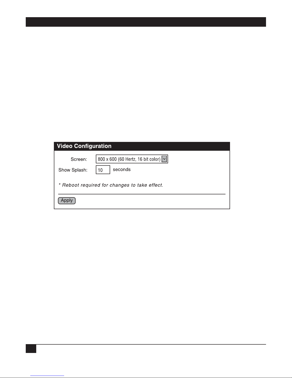
4.3.6 C
ONFIGURE VIDEO SETTINGS
The Video page is used to configure the video settings for your Remote Video System IP.
Figure 4-19. Video Configuration screen.
Configuration settings on the Video page include:
Screen
The resolution, refresh rate, and color depth of the display screen. Select this value from the drop-down menu.
Show Splash
Type in the amount of time, in seconds, to show the splash screen. Valid values are 0 through 30. A value of 0
disables the splash screen (for example, the Windows startup screen).
A custom splash screen can be uploaded to your Remote Video System IP Display.
Apply button
Click on this button to save the changes.
Page 46

43
4.3.7 CONFIGURE NETWORK COMMUNICATIONS
The Network configuration pages include the following:
• IP Settings: Allow you to change the IP address.
• Network Services: Allow you to enable and disable access to various network services such as ADDP,
RealPort, Encrypted RealPort, Telnet™, HTTP/HTTPS, VNC Client Listen Daemon, VNC Server, etc.
• Advanced Network Settings allow you to alter the Ethernet interface speed and mode, TCP/IP settings,
TCP keep-alive settings, or DHCP settings.
Alternatives for Configuring Network Communications
You can configure a Remote Video System IP in three ways.
• Use dynamic settings. The network auto-assigns all network settings, using a protocol called DHCP. Contact
your network administrator to find out if a DHCP server is available.
• Use static settings. Set all network settings manually. (These settings will not change.) The IP address and
subnet mask are mandatory. The rest are not, but they may be needed for some functions. Contact your
network administrator for the appropriate values.
• Use Auto-IP. Auto-IP will assign your device an IP address immediately after it is plugged in. If you are
running DHCP or ADDP, the Auto-IP address will be overridden and a network compatible IP address will
be assigned. Or, you can assign the device a static IP address.
Additional Considerations
Even if a DHCP server is available, your configuration may work better with static settings. Once set, static
settings will not change, so you and other network devices can always find the Remote Video System IP by the IP
address. With dynamic settings, the DHCP server can change the IP address. This can happen frequently or
infrequently depending on how it has been configured by your network administrator.
When the IP address does change, you and other network devices configured to talk to it will no longer be able
to. You will then need to find the Remote Video System IP again using the RVS Device Setup Wizard on your
CD. You must also reconfigure other network devices that you want to talk to this Remote Video System IP.
View and Change IP Settings, as Needed
The IP Settings page shows how the Remote Video System IP’s IP address is obtained, either by DHCP or by
using a static IP address, subnet mask, and default gateway. If you do not know what these settings mean, or
when you may be asked to supply these values, contact your network administrator. Also see the online help for
descriptions of these settings.
Enable or Disable Network Services
The Network Services page shows a set of common network services that are available for devices and the port
on which the service is running.
You can enable or disable several common network services and configure the TCP port they listen on. Disable
services for security purposes. Disable certain services so that a device is running only those services specifically
needed by the device. As needed, and to improve device security, also disable any nonsecure services, such as
Telnet.
CHAPTER 4: Configuring Devices
Page 47

REMOTE VIDEO SYSTEM IP
44
Network Services that Can Be Enabled or Disabled
Network services that can be enabled or disabled include:
• ARDP: This service controls use of Advanced RVS Device Discovery Protocol. If it is disabled, you can no
longer use the RVS Device Setup Wizard, or RVS Device Discovery utility to locate the device.
• RealPort or Encrypted RealPort: These services control COM port redirection. If disabled, you can’t use
COM port redirection for the device.
• Remote Login (Rlogin): Enables or disables the remote login (rlogin) service. If disabled, users can’t
perform a remote login to the device.
• Remote Shell (Rsh): Enables or disables the remote shell (rsh) service.
• Web Server or Secure Web Server (HTTP and HTTPS): These services control the Web interface. If you
disable them, device users can’t use the Web user interface or Java™ applet to configure, monitor, and
administer the device.
• Telnet: Enables or disables the Telnet service. If disabled, users can’t Telnet to the device.
• SNMP: Enables or disables the use of SNMP. If disabled, SNMP services such as traps and device
information are not used.
• VNC Client Listen Daemon: Remote access to a computer on the network or internet using the VNC
(Virtual Network Computing) protocol. VNC server software must be installed on the remote computer.
The default port number for VNC Client Listen Daemon is 5500.
• VNC Server: Allows users to remotely view what is currently displayed on the screen using a standard VNC
client (viewer). The default port number for VNC servers is 5900.
Port Numbers for Network Services
For each network service, the Port field shows the port that the service is running on. Use the default TCP port
numbers for these services because they are well known by most applications.
Configure Advanced Network Settings
To further define the network interface, use the Advanced Network Settings.
• Explains whether Auto-IP address assignment is enabled or disabled.
• Set the Ethernet Interface speed and duplex mode (Auto, Half-Duplex, or Full Duplex).
• TCP keep-alive settings are set by the DHCP server that assigns your network settings unless you choose to
manually set them. To manually set and override these settings, select Ignore TCP Keep-Alive settings from
DHCP and specify the values for Idle Timeout, Probe Interval, and whether an extra byte should be stored
in TCP keep-alive packets.
Page 48

45
CHAPTER 4: Configuring Devices
4.3.8 CONFIGURE SERIAL PORTS
Use the Serial Port Configuration page to establish a port profile for the serial port of the Remote Video System
IP. The Serial Port Configuration page includes the following information:
• The serial port’s currently selected port profile.
• The serial port’s detailed configuration settings. (This depends on the port profile you select.)
• Links to Basic Serial Settings and Advanced Serial Settings.
Port Profiles
Port profiles allow you to easily configure serial ports by displaying only those items that are relevant to the
currently selected profile. The port profiles you can select include the following.
• RealPort Profile: Allows you to map a COM or TTY port to the serial port.
• Custom: An advanced option to allow full serial port configuration. This profile allows you to view all
settings associated with the serial port. When you use serial ports for the terminal emulator’s host or
keyboard connections, configure those ports for the Custom port profile.
Everything on the Serial Port Configuration screen between the Port Profile Settings and the links to the Basic
and Advanced Serial Settings depends on the port profile you select. Selecting a port profile displays the
relevant information for your profile.
Selecting and Configuring a Port Profile
1. To configure any profile, select Serial Ports.
2. Click the port to be configured.
3. Click Change Profile.
4. Select the appropriate profile and click on the Apply button.
5. Enter the appropriate parameters for each profile. Refer to the online help for more details about settings
and values. Click on the Apply button to save the settings.
Configure Basic Serial Settings
After you select your port profile, the profile settings are displayed. Choose the appropriate features for your
environment. The following information is a brief description of the Basic Serial Settings fields. See the online
help for detailed information about each setting.
• The Description field specifies a port’s optional character string. Use it to identify the device connected to
the port.
• Basic Serial Settings include baud rate, data bits, parity, stop bits, and flow control. The basic serial port
settings must match the connected device’s serial settings. If you do not know these settings, consult the
documentation that came with your serial device. These serial settings may be documented as 9600 8N1,
which means that the device is using a baud rate of 9600 bits per second, 8 data bits, no parity, and 1 stop
bit.
Page 49

REMOTE VIDEO SYSTEM IP
46
When using RealPort (COM port redirection) or RFC 2217, these settings are supplied by applications
running on the PC or server, and the default values on your Remote Video System IP device do not need to
be changed.
Configure Advanced Serial Settings
Use the advanced serial settings to further define the serial interface. You can also define how specific aspects of
TCP and UDP serial communications should operate, including timeouts and whether a socket ID is sent.
TCP Settings
The TCP settings are displayed only when the current port is configured with the Custom Profile. The settings
are as follows:
• Send Socket ID: Include an optional identifier string with the data sent over the network. The Socket ID
can be 1 to 256 ASCII characters. Type in non-printable characters as follows:
Table 4-1. Socket ID non-printable characters.
Character Key Sequence
backspace \b
formfeed \f
tab \t
new line \n
return \r
backslash \\
hexadecimal values \xhh
• Send data only under any of the following conditions: Enable if you need to specify the conditions when the
Remote Video System IP device will send the data read from the serial port to the TCP destination.
- Send when data is present on the serial line: Send the data to the network destinations when a specific
string of characters is detected in the serial data. Enter the string of 1 to 4 characters in the Match String
field. Type in non-printable characters as follows:
Table 4-2. Match String non-printable characters.
Character Key Sequence
hexadecimal values \xhh
tab \t
line feed \n
backslash \\
- Strip match string before sending: Use match string to look for a specific string (a list of characters). The
RVS removes this string of characters from the data before the data is sent to the destination.
- Send after the following number of idle: Send the data after the specified number of milliseconds has
passed with no additional data received on the serial port. This can be 1 to 65,535 milliseconds.
Page 50

47
CHAPTER 4: Configuring Devices
- Send after the following number of bytes: Send the data after the specified number of bytes has been
received on the serial port. This can be 1 to 65,535 bytes.
• Close connection after the following number of idle seconds: Enable to close an idle connection. Use the
Timeout field to enter the number of seconds that the connection will be idle before it is closed. This can
be 1 to 65,000 seconds.
• Close connection when DCD goes low: When selected, the connection will be closed when the DCD (Data
Carrier Detected) signal goes low.
• Close connection when DSR goes low: When selected, the connection will be closed when the DSR (Data
Set Ready) signal goes low.
4.3.9 C
ONFIGURE SYSTEM
SETTINGS
Use the System Configuration page to configure the system settings. On this page, you can:
• Configure device description information including the device name, contact, and location.
• Configure SNMP, including whether SNMP is enabled or disabled, and the types of SNMP traps to be
enabled.
Configure Device Description Information
The Remote Video System IP’s device description includes name, contact, and location. Use this device
description to identify a specific Remote Video System IP when you are working with a large number of devices
in multiple locations.
Configure SNMP
You can use Simple Network Management Protocol (SNMP) to manage and monitor network devices.
Configure your RVS Connect device to use SNMP features, or disable its use entirely for security reasons. To
configure SNMP settings, click the Simple Network Management Protocol link at the bottom of the System
Configuration page. SNMP settings include:
• Enable Simple Network Management Protocol (SNMP): This checkbox enables or disables use of SNMP.
• The Public community and Private community fields specify passwords required to get or set SNMPmanaged objects. To prevent unauthorized access to the device, we recommend changing public and
private community names from their defaults.
- Public community: The password required to get SNMP-managed objects. The default is “public.”
- Private community: The password required to set SNMP-managed objects. The default is “private.”
• Allow SNMP clients to set device settings through SNMP: This checkbox enables or disables the capability
for users to issue SNMP set commands. When the box is not checked (disabled), the RVS device can only
read SNMP commands.
• Enable Simple Network Management Protocol (SNMP) traps: Enables or disables the SNMP traps
generation.
• Destination IP: The IP address of the system to which traps are sent. In order to enable any of the traps, you
must specify a non-zero value.
Page 51

REMOTE VIDEO SYSTEM IP
48
• At the bottom of the page are checkboxes for the SNMP traps that can be used: authentication failure,
login, cold start, and link up traps.
4.3.10 C
ONFIGURE
SECURITY FEATURES
On the security page, you can specify the authentication information required for logging on to the RVS
device.
For the Remote Video System IP, by default there is no password authentication. If you are accessing the
Remote Video System IP by opening the Web user interface or issuing a “telnet” command, no login prompt
appears. If desired, you can enable password authentication. After changing the user name or password, you
will immediately be asked to log back in to the Web interface using the new values.
To further secure your Remote Video System IP, you might want to disable those network services not necessary
to the device or turn off any non-secure network services such as Telnet. See Section 6.2.
4.4 Configuration Through the Command Line
Configuring Remote Video System IPs through the Command-Line Interface consists of entering a series of
commands to set values in the device. The RVS Connect Family Command Reference describes the commands
used to configure, monitor, administer, and operate RVS Connect devices.
4.4.1 A
CCESSING THE COMMAND
LINE
To configure devices using commands, you must first access the command line. You can either launch the
Command-Line Interface from the last page of the RVS Device Setup Wizard or using the “telnet” command.
Enter the “telnet” command from a command prompt on another networked device, such as a server, as
follows:
telnet ip-address
where ip-address is the IP address of the Remote Video System IP. For example:
telnet 192.3.23.5
If security is enabled for the Remote Video System IP, (that is, a username and password have been set up for
logging on to it), a login prompt is displayed. If you do not know the user name and password for the device,
contact the system administrator who originally configured the device.
4.4.2 V
ERIFYING WHICH COMMANDS ARE SUPPORTED
To verify whether a Remote Video System IP Display supports a particular command, online help is available.
For example:
• “help” displays all supported commands for a device.
• “?” displays all supported commands for a device.
• “set ?” displays the syntax and options for the “set” command. You can use this command to determine
whether the device includes a particular “set” command variant.
• “help set” displays syntax and options for the “set” command.
Page 52

49
• “set serial ?” displays the syntax and options for the “set serial” command.
• “help set serial” displays the syntax and options for the “set serial” command.
Commands used to configure RVS devices are listed in Table 4-3.
Table 4-3. Configuration commands.
To Configure Use this Command
system-identifying information set system
general serial port options set serial
serial TCP set tcpserial
a port profile for a serial port set profiles
RealPort configuration options set realport
host name set host
SNMP set snmp
network options set network
network services set service
user and passwords set user newpass
terminal emulation settings set putty
video settings set video
VNC client settings set vncclient
4.5 Batch Capabilities for Configuring Multiple Devices
If you are configuring many Remote Video System IP products at once, you can use the batch configuration
capabilities for uploading configuration files that are available through the RVS Connect Programmer. For
details and command descriptions, see the RVS Connect Family Customization and Integration Guide.
CHAPTER 4: Configuring Devices
Page 53

REMOTE VIDEO SYSTEM IP
50
5. Monitoring Devices
5.1 About Monitoring
You can monitor port, device, system, and network activities for Remote Video System IP. Changes in data flow
may indicate problems or activities that may require immediate attention.
5.2 Monitoring Capabilities from the Web User Interface
SYSTEM I
NFORMATION PAGE
The System Information page (found under Administration on the Web user interface home page) displays
information about your Remote Video System IP Display. Technical Support typically uses it to troubleshoot
problems. The System Information page includes general system information, serial port information, and
network statistics.
General System Information
The General page displays general system information about your Remote Video System IP. Use this page to
monitor and troubleshoot devices.
Figure 5-1. General screen.
Page 54

51
CHAPTER 5: Monitoring Devices
Information on this page includes:
Model
The Remote Video System IP.
MAC Address
A unique network identifier. All network devices must have their own unique MAC address. The MAC address is
on a sticker on your Remote Video System IP. The number is displayed as 12 hexadecimal digits, usually starting
with 00:40:9D.
Firmware Version
The current firmware version that’s running in the Remote Video System IP. Use this information to help locate
and download new firmware.
For firmware updates, call Technical Support.
Boot Version
Lists the current boot version.
POST Version
Lists the current POST version.
CPU Utilization
The amount of CPU resources being used by the Remote Video System IP.
Up Time
The amount of time the Remote Video System IP has been running since it was last powered on or rebooted.
Total/Used/Free Memory
The amount of memory (RAM) available, currently in use, and currently not being used.
Click on the Refresh button to refresh the screen.
Page 55

REMOTE VIDEO SYSTEM IP
52
Serial Port Information
The System Information Serial page lists the serial ports that are configured for your Remote Video System IP.
Click on a port to view more detailed serial port information.
Figure 5-2. System Information, Serial Port screen.
The example shows how serial port information is displayed if the host has RealPort installed and is using the
Ethernet connection for sending serial data. For a serial device configuration (with one serial device configured
as the host), you must configure the serial port connections manually. See Figure 5-3.
Figure 5-3. System Information, Serial Port screen example.
Page 56

53
The Serial Port Diagnostics page provides details to help troubleshoot serial communication problems. To get
to this page, click on the port number in Figure 5-3.
Figure 5-4. Serial Port Diagnostics screen.
Configuration
The Configuration section includes the electrical interface (Port Type) and basic serial settings.
Signals
The serial port signals are green when asserted (on) and gray when not asserted (off). These signals are
defined as follows:
• RTS: Request To Send
• CTS: Clear To Send
• DTR: Data Terminal Ready
• DSR: Data Set Ready
• DCD: Data Carrier Detected
• IFC: Input Flow Control. This signal indicates that the RVS device is operating as if flow control is enabled
for incoming data sent from the serial port connection’s remote side. This signal indicates that flow control
is intended or expected. It does not indicate true state information. If the remote side has a flow-control
mechanism enabled, the RVS device will use it.
CHAPTER 5: Monitoring Devices
Page 57

REMOTE VIDEO SYSTEM IP
54
• OFC: Output Flow Control. This signal indicates that flow control is enabled on the serial port connection’s
remote side, and that the RVS device should stop sending data.
Serial Statistics
The Statistics section includes data counters and error tracking to help you determine the data’s quality that is
being sent or received. If the error counters accumulate, you may have a problem with your RVS device.
Total Data In: Total number of data bytes received.
Total Data Out: Total number of data bytes transmitted.
Overrun Errors: Number of overrun errors—the next data character arrived before the hardware could move
the previous character.
Overflow Errors: Number of overflow errors—the receive buffer was full when additional data was received.
Framing Errors: Number of framing errors received—the received data did not have a valid stop bit.
Parity Errors: Number of parity errors—the received data did not have the correct parity setting.
Breaks: Number of break signals received.
Page 58

55
CHAPTER 5: Monitoring Devices
Network Statistics
Use the Network Statistics information to view more detailed network statistics that may help troubleshoot
network communication problems. The screen displays the statistics gathered since you last rebooted the unit.
Figure 5-5. Network Statistics screen.
Page 59

REMOTE VIDEO SYSTEM IP
56
Network statistics descriptions follow. If any error counter is accumulating at an unexpected rate for that type of
counter, you may have a problem with your Remote Video System IP.
IP Statistics
Datagrams Received: Number of datagrams received.
Datagrams Forwarded: Number of datagrams forwarded.
Forwarding: Displays whether forwarding is enabled or disabled.
No Routes: Number of outgoing datagrams for which no route to the destination IP could be found.
Routing Discards: Number of outgoing datagrams which have been discarded.
Default Time-To-Live: Number of routers an IP packet can pass through before being discarded.
TCP Statistics
Segments Received: Number of segments received.
Segments Sent: Number of segments sent.
Active Opens: Number of active opens. In an active open, the Remote Video System IP is initiating a connection
request with a server.
Passive Opens: Number of passive opens. In a passive open, the Remote Video System IP is listening for a
connection request from a client.
Bad Segments Received: Number of segments received with errors.
Attempt Fails: Number of failed connection attempts.
Segments Retransmitted: Number of segments retransmitted. Segments are retransmitted when the server
doesn’t respond to a packet sent by the client. This is to handle packets that might get lost or discarded
somewhere in the network.
Established Resets: Number of established connections that have been reset.
Currently Established: Number of currently established TCP statistics resets.
Resets Sent: Number of resets sent.
Bytes Established: Number of established bytes.
Bytes Sent: Number of bytes sent.
UDP Statistics
Datagrams Received: Number of datagrams received.
Datagrams Sent: Number of datagrams sent.
Bad Datagrams Received: Number of bad datagrams that were received. This number does not include the
value contained by “No Ports.”
Page 60

57
CHAPTER 5: Monitoring Devices
No Ports: Number of received datagrams that were discarded because the specified port was invalid.
Bytes Received: Number of bytes received.
Bytes Sent: Number of bytes sent.
ICMP Statistics
Messages Received: Number of messages received.
Bad Messages Received: Number of received messages with errors.
Destination Unreachable Messages Received: Number of destination unreachable messages received. A
destination unreachable message is sent to the originator when a datagram fails to reach its intended
destination.
Messages Sent: Number of messages sent.
Destination Unreachable Messages Sent: Number of destination unreachable messages sent. A destination
unreachable message is received by the originator when a datagram fails to be sent to its intended destination.
5.3 Monitoring Capabilities from SNMP
Device monitoring capabilities from SNMP include, among other things:
• Network statistics, defined in RFC 1213, MIB-II.
• Port statistics, defined in RFCs 1316 and 1317.
• Device information, defined in RVS enterprise MIB RVS-DEVICE-INFO.mib.
For more information on the statistics available through the standard RFCs listed above, refer to the RFCs
available on the IETF web site (www.ietf.org). For enterprise MIBs, refer to the description fields in the MIB
text.
5.4 Monitoring Devices from the Command Line
You can issue several commands to monitor devices from the command line:
• display: The “display” command displays real-time information about a device, including:
- General product information including the product name, MAC address, boot, post and firmware versions,
memory usage, utilization and uptime, or the amount of time since the device was booted.
– Memory usage information.
– Serial modem signals.
– Uptime information.
• info: The “info” command displays statistical information about a device over time. Several variations of the
“info” command exist. The screen displays the statistics gathered since the tables containing the statistics
were last cleared. The “info” command displays the following statistics types:
Page 61

REMOTE VIDEO SYSTEM IP
58
- Device statistics. The “info device” command displays product, MAC address, boot, POST and firmware
versions, memory usage, utilization, and uptime.
- Ethernet statistics. The “info ethernet” command displays statistics for the Ethernet interface including the
number of bytes and packets sent and received, the number of incoming and outgoing bytes that were
discarded or that contained errors, the number of Rx overruns, the number of times the transmitter has
been reset, and the number of incoming bytes when the protocol was unknown.
- ICMP statistics. The “info icmp” command displays the number of messages, bad messages, and destination
unreachable messages received.
- Serial statistics. The “info serial” command displays the number of bytes received and transmitted, signal
changes, FIFO and buffer overruns, framing and parity errors, and breaks detected.
- TCP statistics. The “info tcp” command displays the number of segments received or sent, the number of
active and passive opens, the number of bad segments received, the number of failed connection attempts,
the number of segments retransmitted, and the number of established connections that have been reset.
- UDP statistics. The “info udp” command displays the number of datagrams received or sent, bad datagrams
received, and the number of received datagrams that were discarded because the specified port was invalid.
• set snmp: Configures SNMP including SNMP traps (such as authentication failure, cold start, link up, and
login traps). This command also displays current SNMP settings.
• status: Displays a list of sessions or outgoing connections made by “connect,” “rlogin,” or “telnet” commands
for a device. Typically, the “status” command is used to determine which of the current sessions to close.
• who: The “who” command provides a global list of connections. Currently, this list includes those associated
with a serial port or the command-line interface. The “who” command is particularly useful when used with
the kill command. Use it to determine any connections that are no longer needed; they can then be ended
by the “kill” command.
Page 62

59
CHAPTER 6: Administering Devices
6. Administering Devices
6.1 Administration from the Web User Interface
6.1.1 FILE
MANAGEMENT
On the File Management page, you can upload files to the Remote Video System IP such as custom HTML files
or a custom JPEG image. For example, to customize the Web user interface for your Remote Video System IP,
upload a different logo file or splash screen.
Figure 6-1. File Management screen.
Uploading Files
To upload files to your Remote Video System IP, type in the file path and name for the file, or click Browse to
locate and select the file. Click Upload.
Uploading a Custom Splash Screen to Your Remote Video System IP
From the File Management page, you can upload a custom splash screen image file to your Remote Video
System IP. That image appears when the device boots. For example, you could display a splash screen with your
company logo and different screen colors than the ones in the RVS-supplied default.
Page 63

REMOTE VIDEO SYSTEM IP
60
Some guidelines and characteristics about the custom splash screen image:
• The image will be centered on the screen.
• If the image is too big for your configured resolution, it will be clipped.
• The file must be named “splash.jpg.”
• The JPEG file must use the RGB color model. You can create JPEG images with other models, such as
CMYK, but the Remote Video System IP does not support displaying them.
• If the file is not recognized, the small green RVS logo default image will be displayed.
Deleting Files
To delete files from your Remote Video System IP, select the file from the list under Manage Files. Click Delete.
Custom Files Are Not Deleted By Device Reset
Any files uploaded to the file system of a Remote Video System IP from the File Management page are not
deleted by restoring the device configuration to factory defaults, or by pressing the Reset button on the device
(see Section 6.1.4). The RVS prevents you from deleting this so that customers with custom applets and custom
factory defaults can retain them on the device and not have them deleted by a reset. You can only delete such
files by clicking on Delete.
6.1.2 B
ACKUP/RESTORE
DEVICE C
ONFIGURATIONS
Once you have a Remote Video System IP Display configured, back it up. Backup/Restore saves your
configuration settings in case you have problems later if you upgrade your firmware or add hardware. If you
have multiple devices to configure, back up the first device, then download the configuration onto the other
devices.
This procedure shows you how to back up or restore the configuration to a server and to download a
configuration from a server to a file.
1. Open a Web browser and enter the Remote Video System IP’s IP address in the URL window.
2. If security is enabled for the device, a login prompt displays. Type in the device’s user name and password.
If you do not know the user name and password, contact the system administrator who initially set up the
device.
3. Click Backup/Restore from the main menu. The Backup/Restore page appears.
Page 64

61
Figure 6-2. Backup/Restore screen.
4. Choose the appropriate option (Backup or Restore) and select your file.
6.1.3 U
PDATE FIRMWARE AND BOOT/POST CODE
The following procedure shows how to update the Remote Video System IP firmware and/or boot/POST code
from a file on your PC. The Remote Video System IP will automatically determine what type of image you are
uploading. Before uploading the firmware or the boot/POST code, read the Release Notes that are supplied
with the firmware to see if the boot/POST code must be updated before updating the firmware.
Update Firmware from a File on Your PC
This procedure assumes that you have already downloaded the firmware file from Web site.
1. Open a Web browser and type in the Remote Video System IP’s IP address in the URL window.
2. If security is enabled for the Remote Video System IP, a login prompt displays. Type in the device’s user
name and password. If you do not know the user name and password, contact the system administrator
who initially set up the device.
3. Click Update Firmware from the main menu to display the Update Firmware page.
CHAPTER 6: Administering Devices
Page 65

REMOTE VIDEO SYSTEM IP
62
Figure 6-3. Update Firmware screen.
4. Enter the name of the firmware or POST file in the Select Firmware box, or click Browse to locate and
select the firmware or POST file.
5. Click Update.
CAUTION
DO NOT close your browser until the update is complete and you have been prompted
to reboot.
6.1.4 RESTORE
DEVICE C
ONFIGURATION TO FACTORY DEFAULTS
There are two ways to restore a Remote Video System IP’s device configuration to the factory-default settings:
• Restore the configuration from a Web browser. This clears all current settings except the IP address settings
and the administrator password. This is the best way to reset the configuration because you can also back up
the settings (helps to restore the configuration after you have worked through configuration issues). See
Section 6.1.2 for more information.
• Restore the configuration using the Remote Video System IP’s reset button. Use this method if you can’t
access the device from a Web browser.
NOTE
Restoring a Remote Video System IP to its factory-default settings clears all current
configuration settings except the IP address settings and the administrator password.
Files such as custom-interface files and applet files that were loaded into the device
through the File Management page are retained. See Section 6.1.1 for information on
loading and deleting files.
Page 66

63
CHAPTER 6: Administering Devices
Restore the Configuration from the Web User Interface
1. Open a Web browser and enter the Remote Video System IP’s IP address in the URL window.
2. If security is enabled for the device, a login prompt appears. Type in the device’s user name and password.
If you do not know the user name and password, contact the system administrator who initially set up the
device.
3. Click Factory Default Settings from the main menu to display the Factory Default Settings page.
Figure 6-4. Factory Default Settings screen.
4. Choose whether you want to keep the device’s network settings (such as the IP address) and click Restore.
Restore the Configuration Using the Reset Button on the Remote Video System IP
1. Unplug the power to the Remote Video System IP.
2. Press the Reset button on the device’s front panel. See Figure 2-1 in Chapter 2.
3. Hold the reset button while powering up the unit.
4. Hold the button for 20 seconds, then release it.
The default configuration is restored. When the restoration is complete, the device flashes a code (1-5-1).
Page 67

REMOTE VIDEO SYSTEM IP
64
6.1.5 DISPLAY SYSTEM INFORMATION
Display system information gives your Remote Video System IP’s model, MAC address, firmware version, boot
version, and POST version. You can also check your memory available: total, used, and free. It also tracks CPU
percent utilization and the uptime.
Under Administration, click System Information. Select General, Serial, or Network for the appropriate
information. For descriptions these screens, see Section 5.2.
Figure 6-5. System Information screen.
Page 68

65
CHAPTER 6: Administering Devices
6.1.6 REBOOT THE DEVICE
Some changes require you to save the changes and reboot the Remote Video System IP Display.
1. Choose Reboot from the main menu.
Figure 6-6. Main menu, Reboot selected.
2. On the Reboot page, click the Reboot button. Wait approximately 1 minute for the reboot to finish.
NOTE
As needed, you can enable and disable access to various network services (such as
ADDP, RealPort, SNMP, and Telnet). For example, you may want to disable those
services that are not necessary for running or interfacing with the Remote Video
System IP. In the Web user interface, enabling and disabling network services is done
on the Network Configuration page. See Section 4.3.7.
Page 69

REMOTE VIDEO SYSTEM IP
66
6.2 Administration from the Command-Line Interface
You can perform the Remote Video System IP’s administrative tasks from the command line. The following
table summarizes device-administration tasks and the commands used to perform them.
Table 6-1. Administration commands.
Administrative Task Command
Backup/restore a configuration from a backup
TFTP server on the network.
Update firmware. boot
1. Telnet to the device server’s command line interface using a
telnet application or hyperterm.
2. If security is enabled for the device, a login prompt appears.
If you do not know the user name and password, contact the
system administrator who initially set up the device.
3. Issue the command:
#> boot load=host:filename
where host is the IP address of the host that contains the
firmware, and filename is the name of the file to upload.
Reset configuration to factory defaults. revert
or
boot action=factory
Display system information and statistics. info
Reboot the device. boot
Enable/disable network services. set service
Page 70

67
7. Troubleshooting
7.1 Calling Black Box
If you determine that your Remote Video System IP is malfunctioning, do not attempt to alter or repair the
unit. It contains no user-serviceable parts. Contact Black Box at 724-746-5500.
Before you do, make a record of the history of the problem. We will be able to provide more efficient and
accurate assistance if you have a complete description, including:
• the nature and duration of the problem.
• when the problem occurs.
• the components involved in the problem.
• any particular application that, when used, appears to create the problem or make it worse.
7.2 Shipping and Packaging
If you need to transport or ship your Remote Video System IP:
• Package it carefully. We recommend that you use the original container.
• If you are shipping the Remote Video System IP for repair, make sure you include everything that came in
the original package. Before you ship, contact Black Box to get a Return Authorization (RA) number.
CHAPTER 7: Troubleshooting
 Loading...