

Page 1
CUSTOMER
SUPPORT
INFORMATION
Order toll-free in the U.S.: Call 877-877-BBOX (outside U.S. call 724-746-5500)
FREE technical support 24 hours a day, 7 days a week: Call 724-746-5500 or fax 724-746-0746
Mailing address: Black Box Corporation, 1000 Park Drive, Lawrence, PA 15055-1018
Web site: www.blackbox.com • E-mail: info@blackbox.com
MARCH 2003
AC1000A AC1007A
AC1001A AC1008
AC1002A AC1009
AC1003A AC1010
AC1004A AC1011
AC1005A AC1012
AC1006A
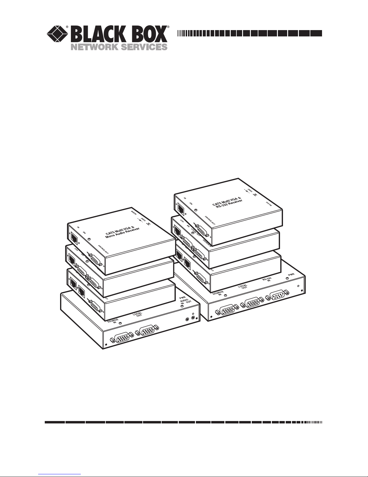
CAT5 Multi VGA System
(VGA and RS-232 or Audio)
Page 2

1
FCC/IC RFI STATEMENTS, EU DECLARATION OF CONFORMITY
FEDERAL COMMUNICATIONS COMMISSION AND INDUSTRY CANADA
RADIO-FREQUENCY INTERFERENCE STATEMENTS
This equipment generates, uses, and can radiate radio-frequency energy, and if not
installed and used properly, that is, in strict accordance with the manufacturer’s
instructions, may cause interference to radio communication. It has been tested
and found to comply with the limits for a Class A computing device in accordance
with the specifications in Subpart B of Part 15 of FCC rules, which are designed to
provide reasonable protection against such interference when the equipment is
operated in a commercial environment. Operation of this equipment in a
residential area is likely to cause interference, in which case the user at his own
expense will be required to take whatever measures may be necessary to correct the
interference.
Changes or modifications not expressly approved by the party responsible for
compliance could void the user’s authority to operate the equipment.
This digital apparatus does not exceed the Class A limits for radio noise emission from digital
apparatus set out in the Radio Interference Regulation of Industry Canada.
Le présent appareil numérique n’émet pas de bruits radioélectriques dépassant les limites
applicables aux appareils numériques de la classe A prescrites dans le Règlement sur le
brouillage radioélectrique publié par Industrie Canada.
EUROPEAN UNION DECLARATION OF CONFORMITY
The manufacturer declares that this product meets the requirements of
EU Directive 89/336/EEC.
Page 3

2
CAT5 MULTI VGA SYSTEM
NORMAS OFICIALES MEXICANAS (NOM)
ELECTRICAL SAFETY STATEMENT
INSTRUCCIONES DE SEGURIDAD
1. Todas las instrucciones de seguridad y operación deberán ser leídas antes de
que el aparato eléctrico sea operado.
2. Las instrucciones de seguridad y operación deberán ser guardadas para
referencia futura.
3. Todas las advertencias en el aparato eléctrico y en sus instrucciones de
operación deben ser respetadas.
4. Todas las instrucciones de operación y uso deben ser seguidas.
5. El aparato eléctrico no deberá ser usado cerca del agua—por ejemplo, cerca
de la tina de baño, lavabo, sótano mojado o cerca de una alberca, etc..
6. El aparato eléctrico debe ser usado únicamente con carritos o pedestales que
sean recomendados por el fabricante.
7. El aparato eléctrico debe ser montado a la pared o al techo sólo como sea
recomendado por el fabricante.
8. Servicio—El usuario no debe intentar dar servicio al equipo eléctrico más allá
a lo descrito en las instrucciones de operación. Todo otro servicio deberá ser
referido a personal de servicio calificado.
9. El aparato eléctrico debe ser situado de tal manera que su posición no
interfiera su uso. La colocación del aparato eléctrico sobre una cama, sofá,
alfombra o superficie similar puede bloquea la ventilación, no se debe colocar
en libreros o gabinetes que impidan el flujo de aire por los orificios de
ventilación.
10. El equipo eléctrico deber ser situado fuera del alcance de fuentes de calor
como radiadores, registros de calor, estufas u otros aparatos (incluyendo
amplificadores) que producen calor.
11. El aparato eléctrico deberá ser connectado a una fuente de poder sólo del
tipo descrito en el instructivo de operación, o como se indique en el aparato.
Page 4

3
NOM STATEMENT, TRADEMARKS
12. Precaución debe ser tomada de tal manera que la tierra fisica y la polarización
del equipo no sea eliminada.
13. Los cables de la fuente de poder deben ser guiados de tal manera que no
sean pisados ni pellizcados por objetos colocados sobre o contra ellos,
poniendo particular atención a los contactos y receptáculos donde salen del
aparato.
14. El equipo eléctrico debe ser limpiado únicamente de acuerdo a las
recomendaciones del fabricante.
15. En caso de existir, una antena externa deberá ser localizada lejos de las lineas
de energia.
16. El cable de corriente deberá ser desconectado del cuando el equipo no sea
usado por un largo periodo de tiempo.
17. Cuidado debe ser tomado de tal manera que objectos liquidos no sean
derramados sobre la cubierta u orificios de ventilación.
18. Servicio por personal calificado deberá ser provisto cuando:
A: El cable de poder o el contacto ha sido dañado; u
B: Objectos han caído o líquido ha sido derramado dentro del aparato; o
C: El aparato ha sido expuesto a la lluvia; o
D: El aparato parece no operar normalmente o muestra un cambio en su
desempeño; o
E: El aparato ha sido tirado o su cubierta ha sido dañada.
TRADEMARKS USED IN THIS MANUAL
Any trademarks mentioned in this manual are acknowledged to be the property of the
trademark owners.
Page 5

4
CAT5 MULTI VGA SYSTEM
Contents
Chapter Page
1. Specifications .................................................................................................5
2. Introduction...................................................................................................8
2.1 Overview ..................................................................................................8
2.2 Package Contents....................................................................................9
2.3 Equipment You May Also Need .............................................................9
2.4 Compatible Cabling................................................................................9
3. Setup and Installation..................................................................................10
3.1 Data Mode Configuration ....................................................................10
3.2 Cabling Considerations ........................................................................10
3.3 Making the Connections ......................................................................10
3.3.1 Connections and Setup in General ............................................10
3.3.2 Connections on the Single-Port VGA/Audio
(AC1000A–AC1001A)..............................................................11
3.3.3 Connections on the Single-Port VGA/RS-232
(AC1004A–AC1005A)..............................................................12
3.3.4 Connections on the Quad Hub VGA/Audio Transmitter
(AC1003A) or Quad Hub VGA/RS-232 Transmitter
(AC1007A)..................................................................................13
3.3.5 Connections on the Dual Daisychainable VGA/Audio
Receiver (AC1002A) or Dual Daisychainable VGA/RS-232
Receiver (AC1006A) ................................................................14
3.3.6 A Typical Single-Port Transmitter–Receiver Application..........16
3.3.7 A Typical Quad Hub Transmitter–Receiver Application ..........17
4. Troubleshooting ..........................................................................................18
4.1 Common Problems...............................................................................18
4.2 Calling Black Box..................................................................................20
4.3 Shipping and Packaging.......................................................................20
Appendix A. Cabling Pinouts...........................................................................21
Appendix B. Setting Sync Signal Output Termination ..................................23
Appendix C. UDB Setting ................................................................................25
Appendix D. Rackmounting Units ..................................................................28
Page 6

5
CHAPTER 1: Specifications
1. Specifications
Cable Required: Between transmitter and receiver(s): Category 5 shielded or
unshielded twisted pair (STP or UTP), though STP is
virtually never necessary
Compliance: CE; FCC Class A, IC Class/classe A
Video Support: VGA, SVGA, XGA, XGA-2, RGBHV, RGB
Resolution and
Refresh Rate:
At 450 ft. (137.2 m) or less: Up to 1280 x 1024 at up to 75 Hz;
At 400 ft. (121.9 m) or less: Up to 1600 x 1280 at up to 75 Hz;
See the Maximum Distance specification
Transmission: Transparent to users (automatic, no delay)
Required Source
Impedance: Video OUT: 75 ohms;
Audio models: Audio OUT (if any): 600 ohms maximum
Required Destination
Impedance: Video IN: 75 ohms;
Audio models: Audio IN (if any): 600 ohms minimum
Bandwidth: Video (3 dB): DC to 8 MHz
Maximum
Differential
Input and Output: Video: 0.55 volts peak-to-peak;
Audio: 0.5 volts peak-to-peak
Differential
Insertion Loss: Video: 0 dB maximum at 4 MHz;
Audio: 1 dB maximum at 1 MHz
Audio
Characteristics: AC1000A–AC1003A only:
Channels: Monaural (mono);
Bandwidth (+1 to -3 dB maximum): 20 Hz to 30 kHz,
measured at 1 volt RMS with 400 ft. (121.9 m) of CAT5
cable between transmitter and receiver
Page 7

6
CAT5 MULTI VGA SYSTEM
Serial
Characteristics: AC1004A–AC1007A only:
Protocol: Asynchronous; transparent to data format;
transparent to data rates up to 19.2 kbps;
Operation: AC1004A–AC1005A: Simplex or full-
duplex, user-selectable;
AC1006A–AC1007A: Simplex (broadcast) only
Maximum
Distance: Total end to end, from source device to farthest destination
device, over good CAT5 cable (assuming A/V source
outputs signal at normal strength):
Up to 450 ft. (137.2 m) at resolutions up to 1280 x 1024 at
up to 75 Hz;
Up to 400 ft. (121.9 m) at resolutions up to 1600 x 1280 at
up to 75 Hz
Connectors: AC1000A: (1) 3.5-mm, (1) RJ-45, (2) HD15 F;
AC1001A: (1) 3.5-mm, (1) RJ-45, (1) HD15 F;
AC1002A: (1) 3.5-mm, (2) RJ-45, (1) HD15 F;
AC1003A: (2) 3.5-mm, (4) RJ-45, (2) HD15 F;
AC1004A: (1) DB9 F (DCE), (1) RJ-45, (2) HD15 F;
AC1005A: (1) DB9 M (DTE), (1) RJ-45, (1) HD15 F;
AC1006A: (1) DB9 M (DTE), (2) RJ-45, (1) HD15 F;
AC1007A: (1) DB9 F (DCE), (4) RJ-45, (2) HD15 F;
All: (1) rear-mounted 5-pin DIN F power inlet
Temperature
Tolerance: Operating: 32 to 104˚F (0 to 40˚C);
Storage: -4 to +140˚F (-20 to +60˚C)
Humidity
Tolerance: Up to 80% noncondensing
Enclosure: Steel
Power: From utility-power (mains) outlet to power inlet, through
detachable external power supply: Input: 100 to 250 VAC
@ 50 or 60 Hz (autosensing);
Output: +5 VDC;
Consumption: 5 watts maximum
Page 8

7
CHAPTER
Size: AC1000A–AC1002A, AC1004A–AC1006A:
1.2"H x 4.1"W x 4.3"D (3.1 x 10.4 x 10.9 cm);
AC1003A, AC1007A: 1.2"H x 5.6"W x 4.5"D
(3.1 x 14.2 x 11.4 cm)
Weight: AC1000A–AC1002A: 0.8 lb. (0.4 kg);
AC1003A, AC1007A: 1.4 lb. (0.6 kg);
AC1004A–AC1006A: 1 lb. (0.5 kg)
CHAPTER 1: Specifications
Page 9

8
CAT5 MULTI VGA SYSTEM
2. Introduction
2.1 Overview
The CAT5 Multi VGA System extends VGA video signals over ordinary Category 5
cable. All models support RGBHV, RGB, and VGA video, and they use a transmitterto-receiver setup. They can be used as video splitters as well as video extenders.
This manual covers CAT5 Multi VGA System Transmitters and Receivers with
Audio (AC1000A–AC1003A) and CAT5 Multi VGA System Transmitters and
Receivers with RS-232 (AC1004A–AC1007A). Their respective Rackmount Kits
(AC1008–AC1012) are discussed in Appendix D.
The video/audio models enable you to broadcast line-level mono audio, along with
video from your computer, to as many as 100 computer monitors up to 450 feet
(137.2 m) away over CAT5.
The video/serial models transmit VGA signals at the same 450-ft. distance to RS232 devices, such as touchscreen displays or newer plasma monitors that have RS232 serial inputs. They do this by transmitting full modem serial signals along with
the video signals over CAT5.
Among the transmitters available for both video/audio and video/serial models
are single-port models and four-port (quad hub) versions. The quad hub
transmitter is used to distribute the same signal to multiple display devices.
Setup and cabling are the same as the single-port transmitters.
When using the quad hub serial transmitter model (AC1003A) with daisychained
receivers, serial communication mode is unidirectionally broadcast. In this mode,
all other CAT5 Multi VGA System devices must be of the simplex serial type.
CAT5 Multi VGA System receivers are available with single or dual daisychainable
connections. The dual daisychainable receiver is used when the same signal is
distributed to multiple display devices across a single CAT5 cable in a daisychain or
loop-through fashion. Setup and cabling are the same as the single-port receiver.
The single-port serial transmitters and single-port and dual daisychainable
serial receivers contain an internal Universal Digital Board (UDB) that can
be reconfigured from its default setting for simplex operation to bidirectional
operation. This way, you can connect touchscreens and high-end video projectors
with interactive features. The bidirectional setting isn’t an option on the the quad
hub models because they broadcast serial data in one direction only.
Page 10

9
CHAPTER 2: Introduction
All models support refresh rates/resolutions up to 1280 x 1024 @ 75 Hz at up to
450 feet (137.2 m) and 1600 x 1280 @ 75 Hz up to 400 feet (121.9 m).
WARNING
This equipment is not intended for, nor does it support, distribution
through an Ethernet network. Do not connect these devices to any sort
of networking or telecommunications equipment!
2.2 Package Contents
You should have received the following when ordering a CAT5 Multi VGA System
transmitter or receiver:
• The transmitter or receiver.
• External power supply (100–250 VAC, 50–60 Hz, autosensing) with cord.
• This manual (transmitters only).
2.3 Equipment You May Also Need
• Rackmount Brackets:
For single-port transmitters or single-port/dual daisychainable receivers:
AC1008 for 1 unit; AC1009 for 4 units; AC1010 for 8 units;
For quad hub transmitters: AC1011 for 3 units; AC1012 for 6 units.
• Audio cable with RCA jacks.
• Video cable with HD15 connectors.
• Serial cable with DB9 connectors.
• CAT5 cable.
• For the single-port audio models, an audio splitter.
2.4 Compatible Cabling
CAT5 cabling for the CAT5 Multi VGA System must be pinned to the TIA-EIA
T568B wiring specification. We also highly recommend that all CAT5 cables
be pre-terminated and tested. Cables terminated on-site or in an existing
infrastructure should be tested before use to ensure compliance with the TIA-EIA
T568B specification. Using incorrectly terminated CAT5 cables can damage the
CAT5 Multi VGA System.
Page 11

10
CAT5 MULTI VGA SYSTEM
3. Setup and Installation
3.1 Data Mode Configuration
For serial 1-port versions only: Configure the internal Universal Digital Board (UDB)
if you want to change the transmitters/receivers from simplex operation (default)
to bidirectional operation. (See Appendix C.) This configuration should be done
before making any cable connections and applying power.
3.2 Cabling Considerations
• We recommend mounting and connecting all cabling to the CAT5 Multi VGA
System components before applying power.
• Makes sure that the CAT5 cable you intend to use has been tested to comply with
the TIA/EIA 568B wiring specification.
• We recommend that you use only CAT5 cable with the CAT5 Multi VGA System.
If you must use CAT5e or CAT6 cable, call Technical Support.
3.3 Making the Connections
3.3.1 C
ONNECTIONS ANDSETUP INGENERAL
This section contains figures showing connections with the specific CAT5 Multi
VGA System models. In general, however, the connection and setup procedure at
both transmitter and receiver ends is as follows:
At the transmitter end:
1. Connect the source video to the CAT5 Multi VGA System transmitter video input
port, which is an HD15 connector labeled SOURCE IN.
2. If desired, attach a local monitor via the local monitor port to LOCAL OUT.
NOTE
The single-port units with audio have a single audio input. So, for audio
capabilities on the attached monitor, you’ll need an audio splitter.
3. Make your audio or serial connections.
For audio versions: Connect the audio input to the AUDIO jack.
For RS-232 versions: Connect the serial input to the RS-232 (DB9 female) port.
Page 12

11
CHAPTER 3: Setup and Installation
4. Connect the CAT5 cable to the transmitter.
5. Apply power on the transmitter. The LED should light and, if there’s a local
monitor attached, a video image should appear on the monitor’s screen.
At the receiver end:
1. Connect the SOURCE OUT HD15 connector to the display unit, and attach any
audio or serial connections depending on the model of CAT5 Multi VGA
System (see Sections 3.3.2 through 3.3.5 for model-specific connections).
2. Make sure that the CAT5 cable connection(s) from the transmitter are secure.
3. Apply power. The LED should light and video should appear on the display
(make sure display is powered ON).
4. For video clarity, adjust the 3-position compensation switch, which optimizes the
image for the length of CAT5 cable used (long, medium, or short).
If there are any problems at either end, see Chapter 4.
3.3.2 C
ONNECTIONS ON THESINGLE-PORT
VGA/A
UDIO
(AC1000A–AC1001A)
The single-port units with audio (AC1000A–AC1001A) support video and
audio signals over CAT5 cable. The audio signal is line-level audio, and powered
speakers are required. Note that there’s a single connection for audio input. If
you use a local station, you’ll need an audio splitter for that jack. (For more
information, call Technical Support.) You can also use the transmitters and
receivers to make video-only connections without mono audio.
Figure 3-1 shows the Single-Port CAT5 Multi VGA System with Audio Transmitter
connections, and Figure 3-2 shows the receiver connections.
Figure 3-1. Transmitter connections on the AC1000A.
CAT5
UTP
Audio
In
Power
Video
Out
Video
In
Page 13

12
CAT5 MULTI VGA SYSTEM
Figure 3-2. Receiver connections on the AC1001A.
3.3.3 C
ONNECTIONS ON THESINGLE-PORT
VGA/RS-232 (AC1004A–AC1005A)
The Single-Port CAT5 Multi VGA System with RS-232 (AC1004A–AC1005A)
supports video and full-modem serial (RS-232) signals over CAT5 cable. You can
also use the transmitters and receivers to make video-only connections without
serial communications.
Figure 3-3 shows the Single-Port CAT5 Multi VGA System with RS-232 Transmitter
connections, and Figure 3-4 shows the receiver connections.
NOTE
Even though both transmitter and receiver units contain audio jacks,
audio is not supported on the RS-232 version. Plugging in audio cables
will interfere with the RS-232 serial communications.
Figure 3-3. Transmitter connections on the AC1004A.
CAT5
UTP
Audio
Out
Power
Video
Out
CAT5
UTP
Serial
In/Out
Power
Video
Out
Video
In
Page 14

13
CHAPTER 3: Setup and Installation
Figure 3-4. Receiver connections on the AC1005A.
3.3.4 C
ONNECTIONS ON THEQUADHUB
VGA/A
UDIOTRANSMITTER
(AC1003A)
ORQUADHUB
VGA/RS-232 T
RANSMITTER
(AC1007A)
The quad hub (four-port) transmitter is used when the same signal is distributed
to multiple display devices. You set it up and cable it the same as you would with
the single-port transmitter. Figure 3-5 shows how connections are made on the
audio quad hub (AC1003A) version, and Figure 3-6 shows how connections are
made on the serial RS-232 quad hub model (AC1007A).
Figure 3-5. Quad hub connections on the AC1003A.
CAT5
UTP
Serial
In/Out
Power
Video
Out
CAT5
UTP
Audio
In/Out
Power
Video
Out
Video
In
Page 15

14
CAT5 MULTI VGA SYSTEM
Figure 3-6. Quad hub connections on the AC1007A.
NOTE
Serial communication mode is unidirectionally broadcast when using
transmitters and daisychained receivers. In this mode, all other CAT5
Multi VGA System devices must be of the simplex serial type. For more
information, contact Technical Support.
3.3.5 C
ONNECTIONS ON THEDUALDAISYCHAINABLE
VGA/A
UDIORECEIVER
(AC1002A)
ORDUALDAISYCHAINABLE
VGA/RS-232 R
ECEIVER
(AC1006A)
The dual daisychainable receiver is used when the same signal is distributed to
multiple display devices on a single CAT5 cable in a daisychain or loop-through
fashion.
Setup and cabling are the same as the single-port receiver, but the dual
daisychainable model has an additional RJ-45 connector for linking to another
dual daisychainable receiver or single-port receiver.
Figure 3-7 shows how connections are made on the dual daisychainable receiver
with audio, and Figure 3-8 shows how connections are made on the dual
daisychainable receiver with RS-232.
CAT5
UTP
Serial
In/Out
Power
Video
Out
Video
In
Page 16

15
CHAPTER 3: Setup and Installation
Figure 3-7. Dual daisychainable receiver connections on the AC1002A.
Figure 3-8. Dual daisychainable receiver connections on the AC1006A.
NOTE
Serial communication mode is unidirectionally broadcast when using
transmitters and daisychained receivers. In this mode, all other CAT5
Multi VGA System devices must be of the simplex serial type. For more
information, contact Technical Support.
CAT5
UTP In
CAT5
UTP Out
Power
Audio
Out
Video
Out
CAT5
UTP In
CAT5
UTP Out
Power
Serial
In/Out
Video
Out
Page 17

16
CAT5 MULTI VGA SYSTEM
3.3.6 A T
YPICALSINGLE-PORTTRANSMITTER–RECEIVERAPPLICATION
Figure 3-9 shows a typical application in which the single-unit transmitter
(AC1000A or AC1004A) is connected over CAT5 to a single-unit receiver
(AC1001A or AC1005A). Although the figure shows optional audio and RS-232
connections, no model supports both audio and RS-232 communications. You can
use the audio or RS-232 units as video-only transmitters/receivers, too.
Figure 3-9. Transmitter to receiver connections.
CAT5
UTP In
CAT5
UTP Out
For AC1004A:
Serial In/Out
For AC1000A:
Audio
In
For AC1005A:
Serial In/Out
For AC1005A:
Connection to
Touchscreen or Other
Serial RS-232 Device
Power
Local VGA Monitor
(or Cascaded Transmitter)
Remote VGA
Monitor
PC CPU
Tower
Power
Transmitter End
(Front and Back of
Unit Shown)
Receiver End
(Front and Back of
Unit Shown)
Video
Out
Video
Out
Switch to Adjust Video Clarity
for Length of CAT5 Cable
Video
In
For AC1001A:
Audio In to
Mono Speaker
Page 18

17
CHAPTER 3: Setup and Installation
3.3.7 A T
YPICALQUADHUBTRANSMITTER–RECEIVERAPPLICATION
Figure 3-10 shows an application in which a Quad Hub CAT5 Multi VGA System
Transmitter is linked to four Single-Port CAT5 Multi VGA System Transmitters.
Optional audio and serial connections are not shown.
Figure 3-10. Quad hub to receiver connections.
(4) CAT5
UTP Out
CAT5 UTP In
CAT5 UTP In
CAT5 UTP In
CAT5 UTP In
Power
Local VGA
Monitor
(or Cascaded
Transmitter)
Remote
VGA
Monitor
Remote
VGA
Monitor
Remote
VGA
Monitor
Remote
VGA
Monitor
Power
Power
Power
Power
Transmitter
(Top of Unit Shown)
Receiver End
(Top of Units Shown)
Video
Out
Video Out
Video Out
Video Out
Video Out
Video
In
PC CPU
Page 19

18
CAT5 MULTI VGA SYSTEM
4. Troubleshooting
4.1. Common Problems
In most cases, nearly every issue with the CAT5 Multi VGA System can be resolved
by checking the CAT5 termination and making sure that it’s pinned to the
TIA/EIA 568B wiring specification. However, there may be other problems that
cause the system to not perform as it’s designed. Below are solutions to the most
common installation errors.
Problem: No video signal at the transmitter local port or at the receiver.
Solution: • Check that both units are powered.
• Make sure the CAT5 cable is terminated correctly per the
TIA/EIA 568B wiring specification.
• Is the display device powered on and functioning?
In some cases, the video termination may be mismatched. The
transmitters and receivers ship with 75-ohm termination as the
default. To disable termination, see Appendix B.
Problem: Video signal is poor.
Solution: • Is the compensation switch on the receiver in the correct
position?
• Check all cable connections.
• The video signal’s refresh rate may be set too high. Reset to a
lower refresh rate in your monitor-configuration menu.
• There may be a delay skew issue. Call Technical Support.
Problem: Audio is poor.
Solution: • Powered speakers are required. Make sure speaker power is
ON.
• Check input source levels from the source device. Make sure
the audio source is not overdriven or underdriven.
Page 20

19
CHAPTER 4: Troubleshooting
Problem: Serial communication doesn’t work correctly.
Solution: • Are the serial devices connected properly? Are the serial
parameters correct for source/destination devices?
• Are the serial cables terminated correctly? If a null-modem
cable is used, it must be placed at the receiver end.
• When using RS-232 transmitters or receivers, the serial signal is
a unidirectionally broadcast mode only. In this mode, all other
CAT5 Multi VGA System devices must be the simplex serial
type. For assistance, contact Technical Support.
• The last device in a quad hub or daisychain configuration must
be a standard receiver unit with a terminated serial board
(default).
Problem: “Blue shift” of video signal (a slight blue haze appears in areas of
the screen that normally would appear black, or a slight blue tint
appears in areas that would normally appear white). This is most
often seen in applications that use inexpensive monitors, but it
sometimes occurs with more expensive equipment.
Solution: 1. Go into the monitor’s menu and select the “Blue-Black Level”
function.
2. Use the appropriate command to reduce the level.
3. Reduce the “Blue-Black Level” until the black areas in the
image truly appear black. For monitors with a “Blue Drive”
adjustment, reduce this setting until the white areas of the
screen appear normal.
Problem: “Green shift” or “green washout” on multimedia signals.
Solution: Please contact Technical Support.
The standard video/serial model (AC1004A–AC1007A) is
designed to function with DC coupled signals in which the black
level is referenced to 0 volts. Nearly all VGA cards function this
way.
Some media servers, however, provide AC coupled signals and
can cause a green color shift in the video. This is a result of the
Page 21

20
CAT5 MULTI VGA SYSTEM
sync clamping on the red and blue channels of the video/serial
model.
For five-component (RGB/H&V) AC coupled video, an optional
DC restoration adapter needs to be installed between the ACcoupled source and the transmitter. Technical Support can
provide you with ordering and installation information.
4.2 Calling Black Box
If you determine that your CAT5 Multi VGA System is malfunctioning, do not
attempt to alter or repair it. It contains no user-serviceable parts. Contact Black
Box at 724-746-5500.
Before you do, make a record of the history of the problem. We will be able to
provide more efficient and accurate assistance if you have a complete description,
including:
• the nature and duration of the problem.
• when the problem occurs.
• the components involved in the problem.
• any particular application that, when used, appears to create the problem or
make it worse.
4.3 Shipping and Packaging
If you need to transport or ship your CAT5 Multi VGA System:
• Package it carefully. We recommend that you use the original container.
• If you are shipping the CAT5 Multi VGA System for repair, make sure you
include everything that came in the original package. Before you ship, contact
Black Box to get a Return Authorization (RA) number.
Page 22
21
APPENDIX A: Cabling Pinouts
Appendix A. Cabling Pinouts
Table A-1. HD15 video connector.
Pin RGBHV
(VGA)
RGBS RGsB
1 Red+ Red+ Red+
2 Green+ Green+ Green+
3 Blue+ Blue+ Blue+
4— — —
5 Gnd Gnd —
6 Red- Red- Red7 Green- Green- Green8 Blue- Blue- Blue-
9— — —
10 Gnd Gnd —
11 Gnd Gnd —
12 — — —
13 H Sync C Sync —
14 V Sync — —
15 Gnd Gnd —
Page 23
22
CAT5 MULTI VGA SYSTEM
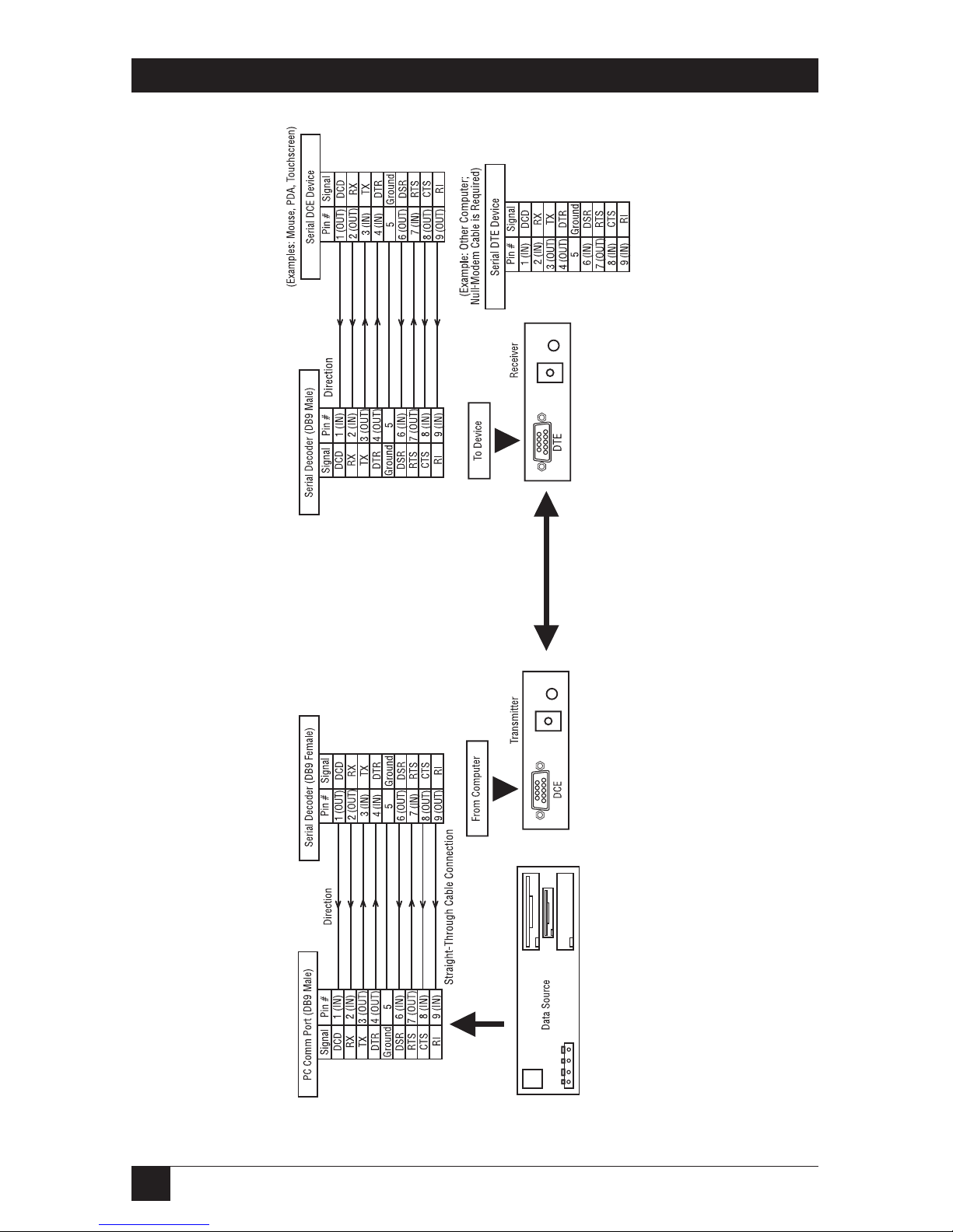
Figure A-1. DB9 serial connector.
Page 24

23
APPENDIX B: Setting Sync Signal Output Termination
Appendix B.
Setting Sync Signal Output Termination
In some cases, it may be necessary to disable the 75-ohm termination of the video
outputs on the CAT5 Multi VGA System units. This can be done by opening the
case of each unit and installing jumpers on the circuit board. The settings
disable/enable the 75-ohm termination on individual units. For instance, changing
a transmitter termination affects the local monitor port only; it doesn’t affect the
receivers. Conversely, changing a receiver affects the output port of the receiver,
not the transmitter. The following diagrams show the jumper locations for each
type of assembly.
Figure B-1. 1-port transmitter.
Figure B-2. 1-port or dual daisychainable receiver.
75-ohm sync termination:
To enable: Both jumpers OUT
To disable: Both jumpers IN
RJ-45
Port
Local
Port
VGA
In
VGA
Port
RJ-45
Port
RJ-45
Port
(dual
models
only)
75-ohm sync termination:
To enable: Both jumpers OUT
To disable: Both jumpers IN
Page 25
24
CAT5 MULTI VGA SYSTEM
Figure B-3. Quad hub transmitter.
VGA
In
RJ-45
Ports
VGA
Out
75-ohm sync termination:
To enable: Both jumpers OUT
To disable: Both jumpers IN
Page 26

25
APPENDIX C: UDB Settings
Appendix C. UDB Settings
The single-port serial transmitters and single-port and dual daisychainable serial
receivers contain an internal Universal Digital Board (UDB) that can be
reconfigured from its simplex operation default setting for bidirectional
operation.
The UDB hardware configuration is done via jumper settings. These jumpers are
used to route signals to the interface port(s) for the DB9 connector and to
configure the transceiver for RS-485 operation.
To access the UDB on these transmitter and receivers:
1. Make sure the unit is powered OFF.
2. If necessary, unplug all cables to the unit.
3. Unscrew the top screw as well as the two set screws in the DB9 connector. Lift
the cover off.
For reference Table C-1 shows the input/output jumper configuration for the DB9
connector as it’s currently pinned on the board.
Table C-1. Input/output configuration on DB9 connector.
RS-232 Transmit Assembly RS-232 Receiver Assembly
JP-1 J2 Pin Signal JP-1 J2 Pin Signal
Y1-A1 1 RS-232 DCD Y1-A1 5 Gnd
Y2-A2 6 RS-232 DSR Y2-A2 9 RS-232 RI
Y3-A3 2 RS-232 RD Y3-A3 4 RS-232 DTR
Y4-A4 7 RS-232 RTS Y4-A4 8 RS-232 CTS
Y5-A5 3 RS-232 TD Y5-A5 3 RS-232 TD
Y6-A6 8 RS-232 CTS Y6-A6 7 RS-232 RTS
Y7-A7 4 RS-232 DTR Y7-A7 2 RS-232 RD
Y8-A8 9 RS-232 RI Y8-A8 6 RS-232 DSR
Y9-A9 5 Gnd Y9-A9 1 RS-232 DCD
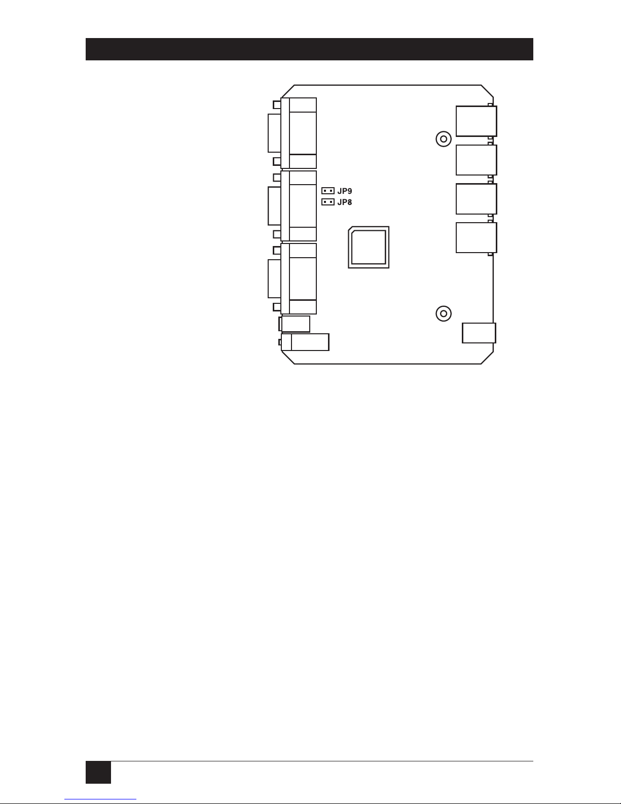
Table C-2 shows the jumper settings for the serial data mode configuration. By
default, the UDB is set for simplex operation.
Page 27

26
CAT5 MULTI VGA SYSTEM
Table C-2. Data mode configuration.
Interface JP-2 JP-3 JP-9 JP-12
Bidirectional RS-232 Tx/Host OUT 3–4 1–2 OUT
3–4
Bidirectional RS-232 Rx/Remote OUT 3–4 1–2 OUT
3–4
Simplex RS-232 Tx/Host OUT 1–2 1–2 IN
3–4
Simplex RS-232 1-Port Rx/Remote OUT 5–6 1–2 IN
3–4
Simplex RS-232 Dual-Port Rx/Remote OUT 5–6 OUT IN
NOTE:
1. JP-2, JP-10, and JP-11 are reserved (not currently used).
2. JP-3 configures the RS-485 transceiver for unidirectional or bidirectional operation.
3. JP-4, JP-5, JP-6, and JP-7 are used for IR configurations only (not currently used).
4. JP-9 controls the RS-485 termination.
5. JP-12 selects simplex or duplex operation.
Figure C-1 shows the board for the Single-Port CAT5 Multi VGA System, RS-232
Transmitter (AC1004A). Figure C-2 illustrates the UDB for both CAT5 Multi VGA
System, RS-232 Receivers (AC1005A and AC1006A).
Figure C-1. AC1004A uncovered, showing jumper settings.
Page 28

27
APPENDIX C: UDB Settings
Figure C-2. AC1005A and AC1006A uncovered, showing jumper settings.
Page 29

28
CAT5 MULTI VGA SYSTEM
Appendix D. Rackmounting Units
The Rackmount Kits include brackets for mounting a single transmitter, single
receiver, or a single dual daisychainable receiver. Figure D-1 shows the 1-Unit
Rackmount Bracket (AC1008), which can be used to mount a single CAT5 Multi
VGA System unit on a wall. Figure D-2 shows the 4-Unit Rackmount Bracket
(AC1009), which holds four units in a 19" x 1U rack.
Not shown are brackets for 8 units and brackets for quad hub transmitters. The 8Unit Rackmount Bracket (AC1010) holds the mounted units like the 4-Unit
Rackmount Bracket (AC1009) but is 2U high instead of 1U high, stacking 4 slots
directly above 4 slots. The 3-Unit Quad Hub Transmitter Bracket (AC1011) is like
the AC1009 but holds 3 units instead of 4 in a 19" wide x 1U high panel. The 6Unit Quad Hub Transmitter Bracket (AC1012) is like the AC1011 but occupies 2U
of space instead of 1U in a 19" rack, stacking 3 quad hub transmitters atop 3 quad
hub transmitters.
Figure D-1. Mounting with the AC1008 kit.
Figure D-2. Mounting with the AC1009 kit.
Support
brace mounts
between
rail and rack
Support
brace mounts
between
rail and rack
10-32 x
1
⁄2"L
panhead screws
10-32 x
1
⁄2"L
panhead screws
(only one shown)
4-40 x
3
⁄8"L flathead screws
Page 30

29
NOTES
Page 31

1000 Park Drive • Lawrence, PA 15055-1018 • 724-746-5500 • Fax 724-746-0746
© Copyright 2003. Black Box Corporation. All rights reserved.
 Loading...