

Page 1
CAT5 Multi VGA System
(VGA and Audio)
.
DECEMBER 2008
AC1000A-R3
AC1001A-R2
AC1002A-R3
AC1003A
AC1013A-R2
AC1014A-R2
AC1211A
CUSTOMER
SUPPORT
INFORMATION
Order toll-free in the U.S.: Call 877-877-BBOX (outside U.S. call 724-746-5500)
FREE technical support 24 hours a day, 7 days a week: Call 724-746-5500 or fax 724-746-0746
Mailing address: Black Box Corporation, 1000 Park Drive, Lawrence, PA 15055-1 018
Web site: www.blackbox.com • E-mail: info@blackbox.com
Page 2

CAT5 MULTI VGA SYSTEM
Page 3
FCC/IC RFI STATEMENTS, EU DECLARATION OF CONFORMITY
FEDERAL COMMUNICATIONS COMMISSION AND INDUSTRY CANADA RADIO FREQUENCY
This equipment generates, uses, and can radiate radio-frequency energy, and if not installed and used properly,
that is, in strict accordance with the manufacturer’s instructions, may cause interference to radio communication.
It has been tested and found to comply with the limits for a Class A computing device in accordance with the
specifications in Subpart B of Part 15 of FCC rules, which are designed to provide reasonable protection against
such interference when the equipment is operated in a commercial environment. Operation of this equipment in
a residential area is likely to cause interference, in which case the user at his own expense will be required to
take whatever measures may be necessary to correct the interference.
This equipment generates, uses, and can radiate radio-frequency energy, and if
Changes or modifications not expressly approved by the party responsible for compliance could void the user’s
not installed and used properly, that is, in strict accordance with the manufac turer’s
authority to operate the equipment.
instructions, may cause interference to radio communication. It has been tested
This digital apparatus does not exceed the Class A limits for radio noise emission from digital apparatus set out
and found to comply with the limits for a Class A computing device in accordance
in the Radio Interference Regulation of Industry Canada.
with the specifications in Subpart B of Part 15 of FCC rules, which are designed to
provide reason able protection against such interference when the equipment is
Le présent appareil numérique n’émet pas de bruits radioélectriques dépassant les limites applicables aux
appareils numériques de la classe A prescrites dans le
operated in a commercial environment. Operation of this equipment in a
residential area i s likely to cause interference , in which case the user at his own
Règlement sur le brouillage radioélectrique publié par Industrie Canada.
expense will be required to take whatever measures may be necessary to correct
the interference.
Changes or modifications not expr essl y approv ed by the pa rty respons ib le
for compliance could v oid the user’s authority to operate the equipment.
This digital apparatus does not exceed the Class A limits for radio noise emission
1. Todas las instrucciones de seguridad y operación deberán ser leídas antes de que el aparato eléctrico sea
from digital apparatus set out in the Radio Interference R egulation of Industry
operado.
Canada.
2. Las instrucciones de seguridad y operación deberán ser guardadas para referencia futura.
3. Todas las advertencias en el aparato eléctrico y en sus instrucciones de operación deben ser respetadas.
4. Todas las instrucciones de operación y uso deben ser seguidas.
Le présent appareil numérique n’émet pas de bruits radioélectriques dépassant les
5. El aparato eléctrico no deberá ser usado cerca del agua—por ejemplo, cerca de la tina de baño, lavabo,
limites applicables aux appareils numériques de la classe A prescrites dans le
sótano mojado o cerca de una alberca, etc..
6. El aparato eléctrico debe ser usado únicamente con carritos o pedestales que sean recomendados por el
fabricante.
Règlement sur le brouillage radioélectrique publié par Industrie Canada.
7. El aparato eléctrico debe ser montado a la pared o al techo sólo como sea recomendado por el fabricante.
8. Servicio—El usuario no debe intentar dar servicio al equipo eléctrico más allá a lo descrito en las
instrucciones de operación. Todo otro servicio deberá ser referido a personal de servicio calificado.
9. El aparato eléctrico debe ser situado de tal manera que su posición no interfiera su uso. La colocación del
aparato eléctrico sobre una cama, sofá, alfombra o superficie similar puede bloquea la ventilación, no se debe
colocar en libreros o gabinetes que impidan el flujo de aire por los orificios de ventilación.
10. El equipo eléctrico deber ser situado fuera del alcance de fuentes de calor como radiadores, registros de
calor, estufas u otros aparatos (incluyendo amplificadores) que producen calor.
11. El aparato eléctrico deberá ser connectado a una fuente de poder sólo del tipo descrito en el instructivo de
operación, o como se indique en el aparato.
The manufacturer declares that this product meets the requirements of
12. Precaución debe ser tomada de tal manera que la tierra fisica y la polarización del equipo no sea eliminada.
EU Directive 89/336/EEC.
13. Los cables de la fuente de poder deben ser guiados de tal manera que no sean pisados ni pellizcados por
objetos colocados sobre o contra ellos, poniendo particular atención a los contactos y receptáculos donde salen
del aparato.
14. El equipo eléctrico debe ser limpiado únicamente de acuerdo a las recomendaciones del fabricante.
15. En caso de existir, una antena externa deberá ser localizada lejos de las lineas de energia.
16. El cable de corriente deberá ser desconectado del cuando el equipo no sea usado por un largo periodo de
tiempo.
17. Cuidado debe ser tomado de tal manera que objectos liquidos no sean derramados sobre la cubierta u
orificios de ventilación.
18. Servicio por personal calificado deberá ser provisto cuando:
A: El cable de poder o el contacto ha sido dañado; u
B: Objectos han caído o líquido ha sido derramado dentro del aparato; o
C: El aparato ha sido expuesto a la lluvia; o
D: El aparato parece no operar normalmente o muestra un cambio en su desempeño; o
E: El aparato ha sido tirado o su cubierta ha sido dañada.
FEDERAL COMMUNICATIONS COMMISSION
INTERFERENCE STATEMENTS
INDUSTRY CANADA
RADIO FREQUENCY INTERFERENCE STATEMENTS
EUROPEAN UNION DECLARATION OF CONFORMITY
The manufacturer declares that this product meets the requirements of
EU Directive 89/336/EEC.
NORMAS OFICIALES MEXICANAS (NOM) ELECTRICAL SAFETY STATEMENT
INSTRUCCIONES DE SEGURIDAD
EUROPEAN UNION DECLARATION OF CONFORMITY
AND
.
1
Page 4

CAT5 MULTI VGA SYSTEM
Contents
Chapter Page
1. Specifications....................................................................................................3
2. Introduction ......................................................................................................5
2.1 Overview.....................................................................................................5
2.2 Package Contents .................................................................................….6
2.3 Equipment You May Also Need.............................................................….6
2.4 Compatible Cabling ......................................................... .... .... ........ .... ..….6
3. Setup and Installation..........................................…...................................…….7
3.1 Making the Connections............................…........................................…..7
3.1.1 Connections and Setup in General .........…....................................…7
3.1.2 Transmitter Connections…………. .........…............................. .......…8
3.1.3 Receiver Connections……………. .. .......…....................................…9
3.2 Receiver Adjustments...............................….......................................……11
3.2.1 AC1001A-R2……………………….......... .…... .... ........ .....................…11
3.2.2 AC1002A-R3, AC1013A-R2, AC1014A-R2....................................…12
3.2.3 Skew Compensation..……………...........…............................. .......…13
3.3 Typical Applications..…..................................…..................................…...14
4. Troubleshooting............................................ ... . ... .... .........................................15
4.1 Common Problems ................................... ... .............................................15
4.2 Calling Black Box ................................. .... .................................................16
4.3 Shipping and Packaging ...........................................................................16
Append ix A. Cabli ng Pinouts.......................... ....... .............................................. .17
Appendix B. DC Restoration Setting ........... .... . ...................................................19
Appendix C. Receiver Video Settings..................................................................20
Appendix D. Rackmounting Units .......................................................................21
Appendix E. Daisy Chain Termination.................................................................22
Appendix F. DDC Modes……………......... ..........................................................23
Appendix G. Sync Modes……………..................................................................24
2
Page 5

SPECIFICATIONS
1.Specifications
Cable Required: CatX (5/5e/6) UTP
Compliance: CE; FCC Class A, IC Class/clas se A
Video Support: RGBHV, RGB, YUV, S-Video, composite, 75 ohm.
Audio Support: 2 Channels Right/Left Summed (mono output)
Resolution and (receiver dependent)
Refresh Rate: AC1001A-R2 1366x768, 720P
AC1002A-R3 1920x1080, 1080P;
AC1211A 1920x1080, 1080P;
AC1013A-R2 1920x1080, 1080P;
AC1014A-R2 1920x1080, 1080P;
See the Maximum Distance specification
Maximum (receiver dependent)
Distance: AC1001A-R2 500 ft (152 m)
AC1002A-R3 600 ft (183 m)
AC1211A 600 ft (183 m)
AC1013A-R3 1200 ft (366 m)
AC1014A-R2 2000 ft (610 m)
Skew (included for models below only).
Compensation: AC1211A Included
AC1013A-R2 Included
AC1014A-R2 Included
Power: All models except below: +5 VDC (5W max)
AC1014A-R2 +12VDC (6W max)
Temperature
Tolerance: Operating: 32 to 104°F (0 to 40°C);
Storage: -4 to +140°F (-20 to +60°C)
Humidity
Tolerance: Up to 80% noncondensing
Enclosure: Steel
.
3
Page 6

CAT5 MULTI VGA SYSTEM
Connectors: Transmitters:
AC1000A-R3: (1) 4 captive screw , (1) RJ-45, (2) HD15 F;
AC1003A: (2) 3.5-mm, (4) RJ-45, (2) HD15 F;
Receivers:
AC1001A-R2: (1) 3.5-mm, (1) RJ-45, (1) HD15 F;
AC1002A-R3: (1) 4 captive screw, (2) RJ-45, (1) HD15 F;
AC1211A: (1) 4 captive screw, (2) RJ-45, (1) HD15 F;
AC1013A-R2: (1) 4 captive screw, (2) RJ-45, (2) HD15 F;
AC1014A-R2: (1) 4 captive screw, (2) RJ-45, (1) HD15 F;
All: (1) power inlet
Size: Transmitters:
AC1000A-R3: 1.2"H x 4.1"W x 4.3"D (3.1 x 10.4 x 10.9 cm)
AC1003A: 1.2"H x 5.6"W x 4.5"D (3.1 x 14.2 x 11.4 cm)
Receivers:
AC1001A-R2: 1.0”H x 3.1” W x 3.7” D (2.2 x 7.9 x 9.5 cm)
AC1002A-R3: 1.2”H x 5.5”W x 3.6”D (3.0 x 14.0 x 9.2 cm)
AC1211A: 1.2”H x 5.5”W x 3.6”D (3.0 x 14.0 x 9.2 cm)
AC1013A-R2: 1.2”H x 5.5”W x 3.6”D (3.0 x 14.0 x 9.2 cm)
AC1014A-R2: 1.2”H x 5.6”W x 6.2”D (3.0 x 14.2 x 15.7 cm)
Weight: Transmitters:
AC1000A-R3: 0.8 lb. (0.4 kg);
AC1003A: 1.4 lb. (0.6 kg);
Receivers:
AC1001A-R2: 0.6 lb. (0.3 kg);
AC1002A-R3: 1.0 lb. (0.5 kg);
AC1211A: 1.0 lb. (0.5 kg);
AC1013A-R2: 1.0 lb. (0.5 kg);
AC1014A-R2: 2.0 lb. (0.9 kg);
4
Page 7

CHAPTER 2: INTRODUCTION
.
2. Introduction
2.1 Overview
The CAT5 Multi VGA System for Video and Audio extends video and audio signals
over ordinary Category 5 cable. All models support RGBHV, RGB, and VGA video,
and they use a transmitter-to-receiver set up.
This manual covers the following CAT5 Multi VGA System Transmitters and
Receivers:
Transmitters:
AC1000A-R3 Single port transmitter
AC1003A 4 port Quad hub transmitter
Receivers
AC1001A-R2 500 ft range
AC1002A-R3 600 ft range, daisy chainable
AC1211A 600 ft range, daisy chainable (incl skew comp)
AC1013A-R2 1200 ft range, daisychainable (incl skew comp)
AC1014A-R2 2000 ft range, daisy chainable (incl skew comp)
The video/audio models enable you to broadcast line-level mono audio, along with
video from your computer, to as many as 100 computer monitors to various cabl e
distances depending upon receiver in use.
Among the transm itters available for both video/audio models are single-port
models and four-port (quad hub) versions. The quad hub transmitter is used to
distribute the same signal to multiple display devices.
CAT5 Multi VGA System receivers are available with single or dual daisychainable
connections. The dual dais ychai na ble re cei ve r is used when the same sig n al is
distributed to multiple display devices across a single CAT5 cable in a daisychain
or loop-through fashion. Setup and cabling are the same as the single-port
receiver.
You can daisy chain within the rated distance of the receiver. For example, an
AC1002A-R3 can be daisy chained within 600 ft of the transmitter. It is possible to
daisy chain out of a shorter range receiver into a longer range receiver. Fo r
example, when daisy chaining over 600 ft, an AC1002A-R3 can be daisy chained
to an AC1013A-R2 over 600 ft. up to 1200 ft.
A maximum of 12 units may be daisy chained.
5
Page 8

CAT5 MULTI VGA SYSTEM
WARNING
This equipment is not intended for, nor does it support, distribut ion
through an Ethernet network. Do not connect these devices to any sort
2.2 Package Contents
You should have receive d the following when ordering a CAT5 Multi VGA Syste m
unit:
• The transmitter or receiver.
• External power supply (100–250 VAC, 50–60 Hz, autosensing) with cord.
• This manual.
2.3 Equipment You May Also Need
• Rackmount Brackets (see Appendix D)
• Audio cable
• Video cable
• CAT5 cable
2.4 Compatible Cabling
The CAT5 Multi VGA System products are compatible with Cat5/5e/6 data cabling as
well as skew free CAT5/5e cabling manufactured for video applications. Note that some
skew free Cat5 is specific to a particular vendor and is not compatible with these
products. Please ensure any skew free CAT5 cable is non-proprietary prior to purchase/
installation.
CAT6 cable, due to the manufacture method, can exhibit muc h greater skew than
standard CAT5/5e and may require skew compe nsation beyond what the standard
product offers.
CAT5/5e/6 cabling for the CAT5 Multi VGA Series must be pinned to the TIA-EIA
T568B wiring specification (see Appendix A) We also highly recommend that all CAT5
cables be pre-terminated and tested. Cables terminated on-site or in an existing
infrastructure should be tested before use to ensure compliance with the TIA-EIA
T568B specification. Using incorrectly terminated CAT5 cables can damage the units.
of networking or telecommunications equipment!
6
Page 9

CHAPTER 3: Setup and Installation
3. Setup and Installation
3.1 Making the Connections
3.1.1 CONNECTIONS AND SETUP IN GENERAL
This section contains figures showing connections with the specific CAT5 Multi
VGA System models. In general, however, the connection and setup procedure at
both transmitter and receiver ends is as follows (see sections 3.1.2, 3.1.3 for
typical connections and se c tion 3.3 for typical applications):
At the transmitter end:
1. Connect the source video to the CAT5 Multi VGA System transmitter video
input port, which is an HD15 connector labeled SOURCE IN.
2. If desired, at tach a local monitor via the l ocal monitor port to LOCAL OUT.
3. Make your audio connections.
Connect the audio input to the AUDIO connector Pins 1 (Left Audio +) , 2
(ground), 3 (Right Audio +) for the AC1000A-R3 or the 3.5mm audio jack for the
AC1003A.
4. Connect the CAT5 cable to the transmitter.
5. Apply power on the transmitter. The LED should light and, if there’s a local
monitor attached, a video image should appear on the monitor’s screen.
At the rece iver end:
1. Connect the SOURCE OUT HD15 connector to the display unit, and attach
any audio connection s depending on the model of CAT5 Mult i V GA
System (see Sections 3.1.3 for model-specific connections).
2. Make sure that the CAT5 cable connection(s) from the transmitter are secure.
3. Apply power. The LED should light and video should appear on the display
(make sure dis play is powered ON).
4. For video clarity, see Section 3.2 for individual receiver adjustments.
If there are any problems at either end, see Chapter 4.
.
7
Page 10

CAT5 MULTI VGA SYSTEM
3.1.2 T
RANSMITTER CONNECTIONS:
Figure 3-1. Transmitter connec tions on the AC1000A-R3.
Figure 3-2. Quad hub connections on the AC1003A.
8 8
Page 11

3.1.3 RECEIVER CONNECTIONS:
Figure 3-3. Receiver connections on the AC1001A-R2.
CHAPTER 3: Setup and Installation
.
Figure 3-4. Receiver connections on the AC1002A-R3.
9 9
Page 12

CAT5 MULTI VGA SYSTEM
3.1.3 RECEIVER CONNECTIONS:
Figure 3-5. Receiver connections on the AC1013A-R2.
Figure 3-6. Receiver connections on the AC1014A-R2.
10
Page 13

CHAPTER 3: Setup and Installation
3.2 RECEIVER ADJUSTMENTS:
This section details the tuning and adjustments for each receiver. The CAT5 Multi
VGA system receivers hav e a single adj ustme nt to compe nsa te for diff eren t Ca t5
cable lengths. Thi s EQ process is easy and simple to do and must be done once
unless the unit is moved to a different location.
Skew compensation is also shown—this does not apply to all receiver units.
3.2.1 AC1001A-R2 A
DJUSTMENTS
The only adjustments required on the AC1001A-R2 receiver are the SW
positions 4 and 5 which must be set to compensate for cable length. Using the
table below as a guide, turn SW positions ON or OFF for best picture cla rit y
(ON = down, OFF = up):
Cable distance EQ settings
Cable Length 4 5
(0-125 Ft)
(125-250 Ft)
(250-375 Ft)
(375-500 Ft)
OFF OFF
ON OFF
OFF ON
ON ON
.
Table 3-1. AC1001A-R2 EQ adj ustment.
11
Page 14

CAT5 MULTI VGA SYSTEM
3.2.2 AC1 0 0 2A-R3, AC 1 2 1 1A, AC10 1 3 A-R2, AC1 0 1 4A-R2 AD J U S T M E N T S
An image utility should be included with the receiver. If it cannot be located, contact
Black Box Technical Support.
NOTE: TURN KNOB SLOWLY DURING ADJUSMENT PROCEDURE. Turning too
fast may result in missing the proper EQ setting resulting in picture loss.
To Reset EQ and Skew values to 0, remove power, push and hold EQ/Skew Knob
in and re-apply power.
1. Push EQ/Skew knob in once so that the R/G/B LED is white (AC1002A-R3,
AC1211A, AC1013A-R2) or all three RGB LED’s are on (AC1014A-R2).
2. Turn the EQ/Skew knob clockwise until the shadow next to the black box just
disappears. The brightness in the white area should be the same as the white area
above and below the black box. The Cable Length LEDs will turn on for indicated
cable distances (AC1014A-R2). Starting from zero feet to 600/1200/2000 may take
some time. Please continue turning the knob for best picture quality.
3. Press and release EQ/Skew knob until the R/G/B LED (AC1002A-R3, AC1211A,
AC1013A-R2) is off, or all three RGB LED’s are off (AC1014A-R2).
LEDs for
Skew adjustment
AC1002A-R3, AC1211A
AC1013A-R2
EQ Adjust
Figure 3-7. Image Adjustment Utility.
12
Adjust
Knob
LEDs for
Skew adjustment
AC1014A-R2
Cable length
LEDs
EQ Adjust
Adjust
Knob
Page 15

CHAPTER 3: Setup and Installation
3.2.3 Skew Compensation Settings
The AC1211A, AC1013A-R2, AC1014A-R2 receivers are available with an optional
skew compensation module to adjust for signal timing differences due to differing pair
lengths within the CAT5 cable. Using the delay signals, skew may be compensated
from 2 to 65 nanoseconds in 2 nanosecond increments on each individual color pair.
If skew compensation is required, but the skew comp module is not installed, call for
technical assistance.
An image file is available to assist in these settings. See F igure 3-8 for an example.
1. To adjust individual colors, press the EQ/Skew knob until the desired color LED is
on for the R/G/B LED (AC1211A, AC1013A-R2) or the desired color LED is lit
(AC1014A-R2). The LED color corresponds to the color channel being adjusted.
2. Using the image utility, turn knob to add/subtract delay timing until a single
vertically aligned line of red, green, blue is obtained.
3. When complete press EQ/Skew knob until R/G/B LED (AC1211A, AC1013A-R2) is
off or all LED’s are off (AC1014A-R2).
Not all colors will have the same delay settings.
.
Figure 3-8: Image Adjustment Utility—Skew
13
Page 16

CAT5 MULTI VGA SYSTEM
3.3 TYPICAL APPLICATIONS
Figures 3-9 to 3-11 show typical applications:
Figure 3-9. Point to Point Application
14
Figure 3-10. 4 Display Distribution
Figure 3-11. Daisy Chain Distribution
Page 17

CHAPTER 4: Troubleshooting
.
4. T roubleshooting
4.1. Common Problems
In most cases, nearly every issue with the CAT5 Multi VGA System can be
resolved by checking the CAT5 termination and making sure that it’s pinned to the
TIA/EIA 568B wiring specification. However, there may be other problems that
cause the system to not perform as it’s designed. Below are solutions to the most
common installation errors.
Problem: No video signal at the transmitter local port or at the receiver.
Solution: • Check that bo th units are power ed.
• Make sure th e CAT5 cable is terminated correctly per the
TIA/EIA 568B wiring specification.
• Is the display de vice powered on and functioning?
• There may be a DDC error. See Appendix F.
• In 1080P modes, fixed sync may be necessary. See Appendix
G.
Problem: Video signal is poor.
Solution: • Have all receive r settings been f i nished (see sections 3.2).
• Check all cable connection s.
• The video signal’s refresh rate may be set too high. Reset to a
lower refresh rate in your monitor-configuration menu.
• There may be a delay skew issue. Call Tec hnical Support.
Problem: Audio is poor.
Solution: • Powered speakers are required. Make sure speaker power is
ON.
• Check input s o urce levels from the source device. Make sure
the audio source is not overdriven or underdriven.
15
Page 18

CAT5 MULTI VGA SYSTEM
Problem: “Green shift” or “green washout” on multimedia signals.
Solution: Please c ontact Tec hn ical Support.
The standard video/serial model is designed to funct ion with DC
coupled signals in which the black level is referenced to 0 volts.
Nearly all VGA cards function this way.
Some media servers, however, provide AC coupled signals and
can cause a green color shift in the video. This is a result of the
sync clamping on the red and blue channels of the video/serial
model.
For five-component (RGB/H&V) AC coupled video, the
AC1000A-R3 and single port transmitters have optional DC
restoration circuitry that is easily enabled via a dipswitch setting
(see Appendix B).
Quad hub transmitters (AC1003A) do not feature this, however
the local monitor output of the AC1000A-R3 can be used to fix this.
Problem: Notes on Dais y Chaining:
Solution: When d aisy chaining, the maximum cable dist ance is not
increased beyond the rated distance of the receiver used. For
example, an AC1002A-R3 can daisy chain within 600 ft of the
transmitter. It is possible to daisy chain out of a short range
receiver into a longer range receiver. For example, over 600 ft
an AC1002A-R3 can be daisy chained into on AC1013A-R2 which
allows for daisy chaining to 1200 ft.
A maximum of 12 units may be daisy chained together.
If a unit in the middle of the chain loses power or is disconnected
from the chain, all units beyond this point will lose signals.
Note that the middle units must have 4th pair termination off, and
the last unit must have 4th pair termination on. See Appendix E.
4.2 Calling Black Box
If you determine that your CAT5 Multi VGA System is malfunctioning, do not
attempt to alter or repair it. It contains no user-serviceable parts. Contact Black
Box at 724-746-5500.
Before you do, make a record of the history of the problem. We will be able to
provide more efficient and accurate assistance if you have a complete description,
including:
• the nature and duration of the problem.
• when the problem occurs.
• the components involved in the problem.
• any particular application that, when used, appears to create the problem or
make it worse.
4.3 Shipping and Packaging
If you need to transport or ship your CAT5 Multi VGA System:
• Package it carefully. We recommend that you use the original container.
• If you are shipping the CAT5 Multi VGA System for repair, make sure you
include everything that came in the original package. Before you ship, contact
Black Box to get a Return Authorization (RA) number.
16
Page 19

APPENDIX A:Cabling Pinouts
.
Appendix A. Cabling Pinouts
Table A-1. HD15 video connector.
Pin RGBHV
(VGA)
1 Red + Red + Red +
2 Green+ Green+ Green+
3 Blue+ Blue+ Blue+
4 — — —
5 Gnd Gnd Gnd
6 Red- Red- Red7 Green- Green- Green8 Blue- Blue- Blue-
9 — — —
10 Gnd Gnd —
11 Gnd Gnd —
12 — — —
13 H Sync C Sync —
14 V Sync — —
15 Gnd Gnd —
RGBS RGsB
17
Page 20

CAT5 MULTI VGA SYSTEM
Appendix A. Cabling Pinouts
Table A-2. AUDIO conn ector
(AC1002A-R3, AC10 13 A-R2, AC10 14 A-R 2, AC1 000A -R3 ))
PIN Audio
Pin 1
Pin 2
Left Channel
Ground
Pin 3
Pin 4
Right Channel
-
Table A-3. 1/8” (3.5 mm) Audio Connection (AC1003A)
Pin Channel 1 Channel 2
Tip +
Ring +
Sleeve - -
Note: The stereo audio input at t he t r ansmitter is summed and output as
mono audio on both channels at t he receiver.
Table A-4. T568B CAT5 pinout
18
Page 21

APPENDIX B:DC Restoration
.
Appendix B. DC Restoration of AC
coupled source
The Cat5 Multi VGA system is designed to function with DC coupled signals
with the black level referenced to 0 volts. Nearly all VGA cards function this
way. However, some media servers or digital camera devices provide AC
coupled signals and can cause a green color shift in the video. This is a result
of the sync clamping on the Red and Blue channels. The single port
transmitter has been designed with full DC restore capability. A simple switch
setting is all that is required.
The following diagrams show the switch location and settings for the
AC1000A-R3 transmitter assembly.
Note: Switch settings other than shown below may result in unpredictable
performance and are not suppo rted by Black Box.
DC restore / AC coupling options:
Disable: AC Coupling to A
(Default) DC Restore to A
Internal SW5 position 1 OFF (default)
Mode 1 AC Coupling to B
Enable DC Restore to B
Internal SW5 position 1 OFF (default)
Mode 2 AC Coupling to B
Enable DC Restore to A
Internal SW5 position 1 ON
19
Page 22

CAT5 MULTI VGA SYSTEM
Appendix C. Receiver Video Modes
The Cat5 Multi VGA System receivers feature the ability to display five component
RGBHV computer vide o as well as RGBS, RGsB and full component RGB video.
The trans mitter units need no config uration chang es.
The AC1001A-R2 has an external switch (SW3) that controls whether RGBHV or
non-RGBHV signals are in use. Please see silkscreen on the top cover of the unit
for the SW3 position to use.
The AC1002A-R3, AC1013A-R2, AC1014A-R2 feature an auto-sense mode to
determine RGBHV or not is in us e . This mode can be overridden if necessary as
shown below:
Figure C-1. Auto Sync Modes AC1002A-R3, AC1211A, AC1013A-R2
AUTO SYNC MODES:
JP8 controls sync clamping circuitry and works with the
external sw i t ch labe l e d AUTO CL AMP.
The default sync mode is AUTO CLAMP OFF which will
autosense between RGBHV and non-RGBHV signals.
Turning the External AUTO CLAMP switch ON will set the
sync clamp m ode to RGBHV vide o modes
If non-RGBHV video is des ired with AUTO CLAMP ON,
jumper JP8 must be set to IN.
Figure C-2. Auto Sync Modes AC1014A-R2
JP13 controls sync clamping circuitry and has 3
settings depending on the video signal in use:
RGBHV computer video with separate
horizontal and vertical sync:
Jumper JP13 to positions 1-2
Non RGBHV video, component RGB/YUV, Svideo, compos ite video or RGsB video:
Jumper JP13 to positions 2-3
Auto sense video mode:
JP13 non-jumpered.
20
Page 23

APPENDIX D:Rackmounting Units
Appendix D. Rackmounting Units
The Cat5 Multi VGA System components can be rack mounted in 19 ” wide
cabinets. Below is a table showing the various rackmount kits available .
Figure D-1 shows a typical rackmount application.
Transmitters:
PN Rackmount PN Description
AC1000A-R3 AC1009 19” 1U high kit for 4 uni ts horizontally.
AC1010 19” 2U high kit for 2 rows of 4 units
AC1003A AC1011 19” 1U high kit for 3 units horizontally.
AC1012 19” 2U high kit for 2 rows of 3 units
Receivers:
AC1001A-R2 no rackmount options
AC1002A-R3, AC1211A, AC1013A-R2, AC1014A-R2
Use AC1011 or AC1012 described above
Figure D-1. Mounting with the AC1009 kit.
.
21
Page 24

CAT5 MULTI VGA SYSTEM
Appendix E. Daisy Chain Termination
The Cat5 Multi VGA Syst em receiver units with a UTP output can be daisy chained
along a single ca t5. This applies to the AC100 2A-R3, AC1013A-R2, and th e
AC1014A-R2. The AC1001A-R2 does not have this capability.
When daisy chaining, it is important to ensure units have proper termination at
the end, but no termination in the middle units. This has no affect on the video
signals, but will affect the audio signals.
To enable/disable termination on the AC1002A-R3 and AC1013A-R2, the
external TERM switch is used. To enable termination at the end of a daisy
chain, set the TERM switch to ON. Set switch to OFF when units are in the
middle of the daisy chain. See figure below:
To enable/disable termination on the AC1014A-R2, two jumpers internally
need to be in or out. This involves removing the top cover assembly and
installing or removing two jumpers. See figure below for the locations:
Term switch for
daisy chaining
To enable TERM, place
jumpers on JP16 and JP17
To disable TERM, remove
jumpers on JP16 and JP17
22
Page 25

APPENDIX F: DDC Modes
.
Appendix F. DDC Modes
The AC1000A-R3 features the ability to send DDC/EDID display identifiers to the video
source in order to determine display capabilities. The DDC is a data communication
channel used in plug and play devices to accurately report a displays capabilities and
identify the manufacturer. If this data is not available, the video source may revert to a
low resolution or not display at all.
The AC1000A-R3 features the ability to report a Universal Display (MRI Magic Display)
that supports most popular VESA standards in standard or widescreen formats as well
as the ability to clone an actual displays DDC information that is attached to either the
local output of the transmitter or copied from an actual display.
The AC1000A-R3 transmitter unit has 3 DDC modes of Operation:
Mode 1: DDC Mock Mode
This is the default mode which uses generic DDC information stored within the
transmitter and reports this to the video source when requested.
To activate this mode, set the DDC Mode switch to the A position.
Mode 2: DDC from Local Monitor Port
The DDC information is transferred from a display connected to the local port of the
transmitter back to the video source. The local monitor must remain conn ect ed at all
times.
To activate this mode, set the DDC Mode switch to the B position.
Mode 3: Copy DDC information from a display into the AC1000A-R3 m emory.
In this mode, DDC information is first copied from a display into the AC1000A-R3
transmitter and stored in non-volatile RAM. Then the transmitter is connected to a video
source and reports the copied DDC information to the video source when requested.
To activate this mode, set the DDC Copy switch to the B position and do
the following:
• Connect Display to the Local monitor port on the transmitter
• Set DDC Copy s witch to B
• Press the Enter button
• DDC LED will flash 3 times indicating a successful copy.
• Disconnect display and reconnect video source.
To restore the default generic DDC information:
• Set DDC Copy switch to A, then press the Enter button
• The DDC LED will flash 2 times to confirm restoration.
DDC Control s
23
Page 26
CAT5 MULTI VGA SYSTEM
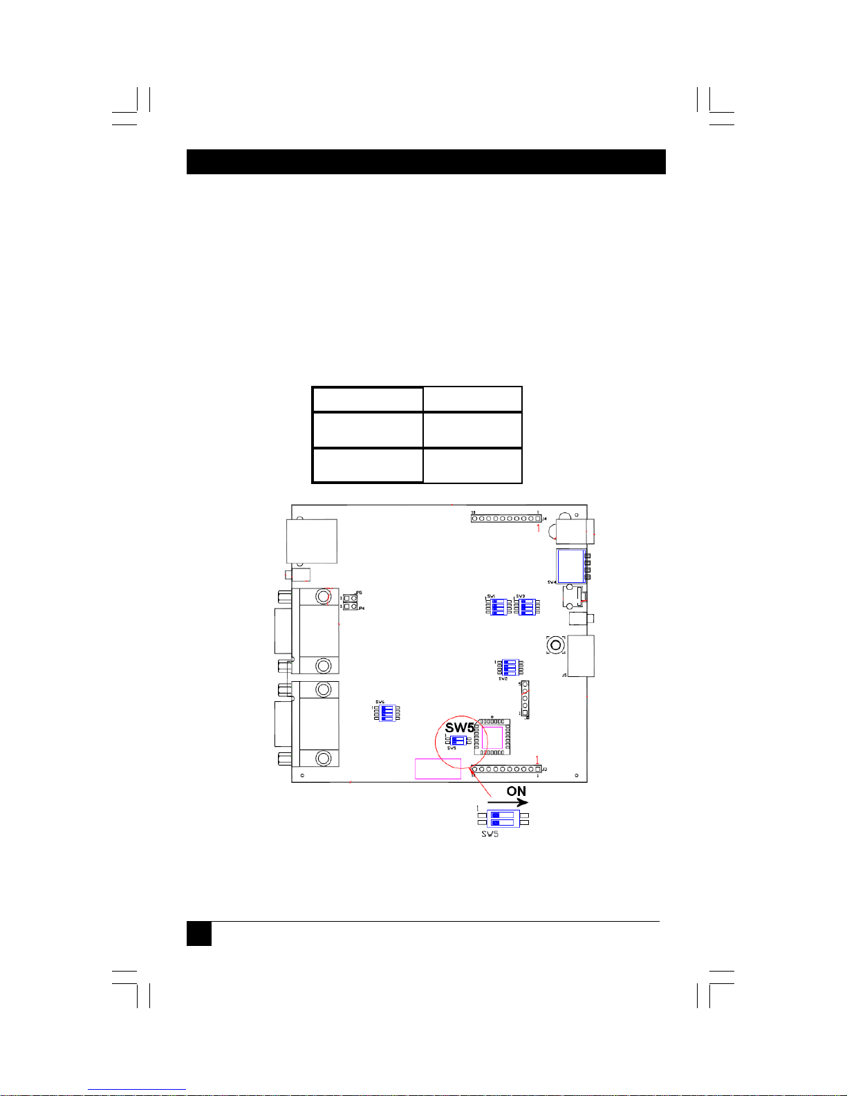
Appendix G. Setting Sync Mode
The AC1000A-R3 has the capability for fixed and agile sync. The default sync mode
setting is for agile sync which replicates the source sync polarity signals. However
some displays require a fixed sync polarity that is not possible to change at the video
source. 1080P signals may also require this mode if the sync is a very narrow pulse.
NOTE: Both transmitter and receiver must have the same settings.
Not all transmitter/receivers support this function.
Jumper Setting
Fixed Sync 1 N/A
Agile Sync (default) 1 N/A
SW5
2 ON
2 Off
24
Page 27

APPENDIX G: Sync Modes
.
Appendix G. Setting Sync Mode
The AC1002A-R3, AC1211A, AC1013A-R2, AC1014A-R2 have the capability for fixed
and agile sync. The default sync mode setting is for agile sync which replicates the
source sync polarity signals. However some displays require a fixed sync polarity that is
not possible to change at the video source.
1080P signals may also require this mode if the sync is a very narrow pulse.
The following details jumper settings to change the sync polarity of the horizontal and
vertical sync signals (Note that jumpers have no affect in agile mode):
AC1002A-R3, AC1211A,
AC1013A-R2 AC1014A-R2
Jumper Setting JP5 JP6 JP7
Fixed Sync IN - -
Agile Sync (default) OUT - -
Horizontal Sync
Positive
Horizontal Sync
Negative
Vertical Sync
Positive
Vertical Sync
Negative
IN
-
- OUT -
- - IN
- - OUT
-
AC1002A-R3, AC1211A,
AC1013A-R2 AC1014A-R2
Sync Mode j umpers
JP5, JP6, JP7
Sync Mode j umpers
JP10, JP11, JP12
Jumper Setting JP10 JP11 JP12
Fixed Sync IN - -
Agile Sync (default) OUT - -
Horizontal Sync
Positive
Horizontal Sync
Negative
Vertical Sync
Positive
Vertical Sync
Negative
IN
-
- OUT -
- - IN
- - OUT
-
25
Page 28

CAT5 MULTI VGA SYSTEM
© Copyright 2008. Black Box Corporation. All rights reserved.
1000ParkDrive•Lawrence,PA15055‐1018•724‐746‐5500•Fax724‐746‐0746
5320013-01 Rev 02
 Loading...