

Page 1
CUSTOMER
SUPPORT
INFORMATION
Order toll-free in the U.S. 24 hours, 7 A.M. Monday to midnight Friday: 877-877-BBOX
FREE technical support, 24 hours a day, 7 days a week: Call 724-746-5500 or fax 724-746-0746
Mail order: Black Box Corporation, 1000 Park Drive, Lawrence, PA 15055-1018
Web site: www.blackbox.com • E-mail: info@blackbox.com
JULY 1993
AC043A
AC044A
S-Video Splitter-8
Composite Splitter-8
O
U
T
P
U
T
78
COMPOSITE Splitter-8
AGC
O
F
F
O
N
G
AIN
C
A
L
G
R
E
E
N
=
U
N
IT
Y
G
A
IN
O
U
T
P
U
T
78
S-Video
Splitter-8
AGC
O
F
F
O
N
GAIN
C
A
L
G
R
E
E
N
=
U
N
IT
Y
G
A
IN
Page 2

1
FCC AND IC STATEMENTS, TRADEMARKS
FEDERAL COMMUNICATIONS COMMISSION
AND
INDUSTRY CANADA
RADIO FREQUENCY INTERFERENCE STATEMENT
This equipment generates, uses, and can radiate radio frequency energy
and if not installed and used properly, that is, in strict accordance with the
manufacturer’s instructions, may cause interference to radio communication.
It has been tested and found to comply with the limits for a Class A
computing device in accordance with the specifications in Subpart J of Part 15
of FCC Rules, which are designed to provide reasonable protection against
such interference when the equipment is operated in a commercial
environment. Operation of this equipment in a residential area is likely to
cause interference, in which case the user at his own expense will be required
to take whatever measures may be required to correct the interference.
Changes or modifications not expressly approved by the party responsible
for compliance could void the user’s authority to operate the equipment.
This digital apparatus does not exceed the Class A limits for Radio noise emission from
digital apparatus set out in the Radio Interference Regulation of Industry Canada.
Le présent appareil numérique n’émet pas de bruits radioélectriques dépassant les limites
applicables aux appareils numériques de la classe A prescrites dans le Règlement sur le
brouillage radioélectrique publié par Industrie Canada.
TRADEMARKS
All applied-for and registered trademarks are the property of their respective owners.
Page 3

2
VIDEO SPLITTERS
NORMAS OFICIALES MEXICANAS (NOM)
ELECTRICAL SAFETY STATEMENT
INSTRUCCIONES DE SEGURIDAD
1. Todas las instrucciones de seguridad y operación deberán ser leídas antes
de que el aparato eléctrico sea operado.
2. Las instrucciones de seguridad y operación deberán ser guardadas para
referencia futura.
3. Todas las advertencias en el aparato eléctrico y en sus instrucciones
de operación deben ser respetadas.
4. Todas las instrucciones de operación y uso deben ser seguidas.
5. El aparato eléctrico no deberá ser usado cerca del agua—por ejemplo,
cerca de la tina de baño, lavabo, sótano mojado o cerca de una alberca,
etc..
6. El aparato eléctrico debe ser usado únicamente con carritos o pedestales
que sean recomendados por el fabricante.
7. El aparato eléctrico debe ser montado a la pared o al techo sólo como
sea recomendado por el fabricante.
8. Servicio—El usuario no debe intentar dar servicio al equipo eléctrico más
allá a lo descrito en las instrucciones de operación. Todo otro servicio
deberá ser referido a personal de servicio calificado.
9. El aparato eléctrico debe ser situado de tal manera que su posición no
interfiera su uso. La colocación del aparato eléctrico sobre una cama,
sofá, alfombra o superficie similar puede bloquea la ventilación, no se
debe colocar en libreros o gabinetes que impidan el flujo de aire por los
orificios de ventilación.
10. El equipo eléctrico deber ser situado fuera del alcance de fuentes de
calor como radiadores, registros de calor, estufas u otros aparatos
(incluyendo amplificadores) que producen calor.
Page 4

3
NOM STATEMENT
11. El aparato eléctrico deberá ser connectado a una fuente de poder sólo
del tipo descrito en el instructivo de operación, o como se indique en
el aparato.
12. Precaución debe ser tomada de tal manera que la tierra fisica y la
polarización del equipo no sea eliminada.
13. Los cables de la fuente de poder deben ser guiados de tal manera que
no sean pisados ni pellizcados por objetos colocados sobre o contra ellos,
poniendo particular atención a los contactos y receptáculos donde salen
del aparato.
14. El equipo eléctrico debe ser limpiado únicamente de acuerdo a las
recomendaciones del fabricante.
15. En caso de existir, una antena externa deberá ser localizada lejos
de las lineas de energia.
16. El cable de corriente deberá ser desconectado del cuando el equipo
no sea usado por un largo periodo de tiempo.
17. Cuidado debe ser tomado de tal manera que objectos liquidos no sean
derramados sobre la cubierta u orificios de ventilación.
18. Servicio por personal calificado deberá ser provisto cuando:
A: El cable de poder o el contacto ha sido dañado; u
B: Objectos han caído o líquido ha sido derramado dentro del
aparato; o
C: El aparato ha sido expuesto a la lluvia; o
D: El aparato parece no operar normalmente o muestra un cambio
en su desempeño; o
E: El aparato ha sido tirado o su cubierta ha sido dañada.
Page 5

4
VIDEO SPLITTERS
Bandwidth — >30 MHz
Rise/Fall times — <10 ns
Connectors — AC043A: 4-Pin Mini-DIN (Female)
AC044A: BNC (Female)
Inputs (1) — Impedance: 75 ohms Y, C
Level: 0 to 1.5 V PP (0 to 210 IRE)
Gain: -6 to +6 db or unity or automatic unity
ref. from pedestal to 100 IRE white.
AGC requires >10 µs IRE white per
field (VIR/VIT signal). Manual gain
has "CAL" detect. LED is green
when Gain = Unity.
Diff. Gain: <0.50%
Diff. Phase: <0.6
Outputs (8) — Impedance:
AC043A: 75 ohms Y, C
AC044A: 75 ohms
Level Max.: >1.8 V PP into 75 ohms
Adjust w/
Gain Control: (Y) 0.714 V PP (100 IRE) Video Out
for <0.5 V (70 IRE) to >1.4 V PP
(196 IRE) Input
DC Restoration: Switchable: Pedestal or Sync
TIP = 0 VDC with ± 1 V offset
on input
Propagation Delay — <10 ns
Size — Width: 7.0" (17.8 cm)
Height: 1.7" (4.2 cm)
Depth: AC043A: 5.5" (14.0 cm)
AC044A: 6.5" (16.5 cm)
Weight — 1 lb. (0.5 kg); Shipping weight: 3 lb. (1.4 kg)
Power — 9 VDC, 1 A, 105- to 130-VAC or 220-VAC plug-
mounted transformer
1. Specifications
Specifications are the same for the S-Video Splitter-8 (AC043A)
and Composite Splitter-8 (AC044A) unless specifically noted.
Page 6

5
CHAPTER 2: Introduction
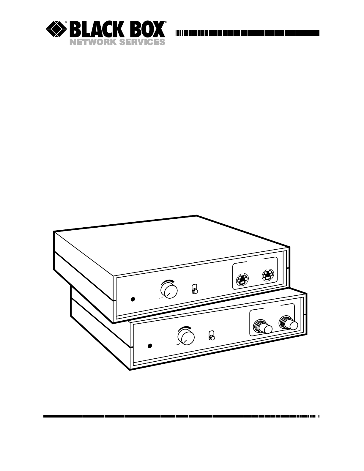
The S-Video Splitter-8 (AC043A)
and Composite Splitter-8 (AC044A)
distribute a video signal from one
source to many video displays. Each
unit features DC Restoration and
Fixed, Manual and Automatic
Gain Controls.
The SVHS Splitter-8 is a 30-MHz
S-Video (Y/C) Distribution
Amplifier for S-VHS, Hi-8,
ED-BETA, and other video
applications that use 4-pin
mini-DIN connectors.
The Composite Splitter-8 is a
30-MHz Composite Video
Distribution Amplifier with
BNC connectors.
Features include:
• 30-MHz bandwidth
• 8 outputs from a single input
• Automatic gain
• Manual gain control
• Unity gain
• Table-top or rack mounting
Your complete package will have
the following:
• The Video Splitter unit.
• 9 VDC, 1 A plug-mounted
transformer
• User Manual
2. Introduction
7
AGC
S-VIDEO
DISTRIBUTION
AMPLIFIER
OUTPUT
OFF
ON
GAIN
CAL
GREEN =
UNITY GAIN
8
Figure 1. Front panel of the Video Splitter
(AC044 shown here).
Page 7

6
VIDEO SPLITTERSVIDEO SPLITTERS
The procedure to install either the
S-Video Splitter-8 (AC043A) or the
Composite Splitter-8 (AC044A) is
the same unless specifically noted.
3.1 Preparation
Place your Video Splitter on a flat
surface. For a permanent installation, you may want to use a
rackmount tray (RM001 or RM002).
You can place up to two (2) units
side by side on the tray.
In a table top installation, a minimum of 3 inches is required behind
the unit in order to connect the
input signal and the output signals
to your monitor.
With multiple video outputs, you
may want to consider placing the
your Video Splitter as close as
possible to the video monitors
in order to conserve wire. It is
important that the video cables
meet your local safety and
community building codes.
3.2 Input Signal Connection
Using the appropriate cable,
connect your video source to
the back-panel connector labeled
“INPUT.”
• AC043 uses the S-Video cable with
4 pin mini-DIN connectors. When
installing the cables, be sure that
the small pins in the mini-DIN
connector are not bent or
damaged prior to inserting
them into the jack on your Video
Splitter. Align the cable connector
with the plastic key down.
• AC044 uses standard video cable
(ETN59) with BNC connectors.
When installing the cables, be
sure that the BNC cable connector
has been turned clockwise to its
locking position.
3. Installation
Figure 2. 4-pin mini-DIN
connector (female)
Plastic Key
will fit into
this hole only
Page 8

7
CHAPTER 3: Installation
3.3 Monitor(s) Connection
Make sure your video monitor(s)
or recording device(s) meets your
local safety and community building
codes. Using the appropriate cable,
connect your monitor(s) to the rearor front-panel connectors on your
Video Splitter that are marked
“OUTPUT.” Connect the other end
of the cable(s) to your monitor(s).
Some monitors are only equipped
with RCA inputs. In these cases
you will need a BNC to male RCA
adapter.
NOTE: Outputs 1 through 6 are located on
the rear of the unit, while outputs
7 and 8 are located on the front. The
front output connections are ideal
for temporary hookup of additional
video displays or recorders.
3.4 Power Connection
To connect your Video Splitter to
an AC power source, first uncoil
the wire attached to the power cube.
Connect the single plug into the
power input jack located on the back
of your Video Splitter. Next, plug
the power cube into a standard AC
power receptacle (105 to 130 VAC).
Check to see if the power indicator
on the front of your Video Splitter
is illuminated.
Figure 3. Back panel of the Video Splitter
(AC043 shown here).
1 2 3 4 5 6
INPUT
SYNC TP
DC RESTORE/
CLAMP
POWER
9VDC
BLACK
OUTPUT
Page 9

8
VIDEO SPLITTERSVIDEO SPLITTERS
4.1 Operation
The operation of the Video Splitter
unit is relatively simple. All connected
output devices (Monitors, Recorders,
etc.) will see the same signal as the
input source. No selection of outputs
is possible.
A
UTOMATIC AND
A
DJUSTABLEGAIN
When the front-panel Automatic
Gain Control (AGC) switch is set
to ON, turn the adjustable gain
counterclockwise to the left until
it clicks into place by the CAL
indicator. The Video splitter will
provide unity gain to each output.
This will be confirmed by the frontpanel LED being green.
When the AGC switch is set to the
OFF position, gain is manually
controlled by the adjustable front-
panel knob. The front-panel LED
will turn red. The output gain can
be adjusted from -6dB to +6dB. The
front-panel LED changes from red
to green to indicate unity gain.
DC R
ESTORE/CLAMP
The DC restore/clamp switch is
located on the back-panel of your
Video Splitter. Set this switch in
the position which yields the
best picture.
For most applications, the switch will
be set in the “BLACK” position (up).
In this position, the output video is
clamped at 0 VDC (see Figure 4).
With the switch in the “SYNC TIP”
position (down), the sync signal
is raised above ground (0 VDC)
(see Figure 5). On some monitors
this will result in a brighter picture.
4. Operation, Troubleshooting
and Maintenance
0 VDC
SYNC
VIDEO
Figure 4. Video output clamped at 0 VDC.
Page 10

9
CHAPTER 4: Operation, Troubleshooting, and Maintenance
P
OWERINDICATOR
The front-panel LED will be lit
whenever the Video Splitter is
being supplied with AC power.
4.2 Troubleshooting
If no power is indicated: Check
the AC source and the power cord
connection on the back panel of
the unit.
If the monitor(s) will not display the
video source image: Check to make
sure that the video source is on and
that it is properly connected to the
Video Splitter. Also make sure
that the monitor(s) are properly
connected to the Video Splitter.
4.3 Maintenance
The AC043 and AC044 Video
Splitters are designed and manufactured to the highest degree of
quality. There are no user-serviceable components inside of the
Video Splitter. We recommend
that the unit be returned for repairs.
0 VDC
SYNC
VIDEO
Figure 5. Sync raised above ground.
Page 11

1000 Park Drive • Lawrence, PA 15055-1018 • 724-746-5500 • Fax 724-746-0746
© Copyright 1993. Black Box Corporation. All rights reserved.
 Loading...