

Page 1

How To Use
Data Communications
with the Watlow
Series 945
User's Manual
Watlow Controls, 1241 Bundy Blvd., P.O.Box 5580, Winona, MN 55987-5580, Phone: 507/454-5300, Fax: 507/452-4507
W945-SA50-9210
March, 1992
Supersedes:
W945-SA40-9119
How to Use Data Communications
Made in the U.S.A.
$5.00
Printed on Recycled Paper
WATLOW Series 945
1
Page 2

Contents
Page Item
3 Data Communications and the Series 945
3 Hardware Interfaces Protocols
3 Communications Wiring
4 RS-422A Interface Pinouts
5 RS-423A Interface Pinouts
(RS-232C Compatible)
6 EIA-485 Interface Pinouts
6 Connecting the Control and Computer
7 Setting Hardware Protocol Switches
7 Network Connections
7 Series 945 Communication Parameters
8 Communications Setup Parameters
10 ASCII and Series 945 Information
11 Series 945 General Message Syntax
11 Message Syntax
11 Data Rules
12 Command List
12 Example Format
13 XON/XOFF Protocol for RS-423A
13 Start and Stop Communicating with the
Series 945 and XON/XOFF
14 XON/XOFF "=" Command Example
15 XON/XOFF "?" Command Example
16 ANSI X3.28 Protocol for RS-422 & EIA-485
16 Device Address
16 Starting Communications in ANSI X3.28
17 Stopping Communications in ANSI X3.28
17 ANSI X3.28 "=" Command Example
18 ANSI X3.28 "?" Command Example
19 "?" Command
20 "=" Command
22 Data Logging
23 Table Printout
23 Statistical Process Control - SPC
24 The Difference Between Control and
Specification Limits
25 Chart and SPC Printout
26 NAKs and Error Codes
26 User Responsibility
27 Index
Figures Item
1 RS-422 Interface Wiring
2 RS-423 Interface Wiring
3 EIA-485 Interface Wiring
4 RS-422/RS-423 Switch Selection
5 General Message Syntax Example
6 XON/XOFF "=" Command Example
7 XON/XOFF "?" Command Example
8 ANSI X3.28 "=" Command Example
9 ANSI X3.28 "?" Command Example
10 Data Logging Interface Wiring
11 Table Printout Example
12 Chart & SPC Printout Example
Tables Item
1 Setup Menu Prompts and Descriptions
2 ASCII Character Set
3 ASCII Control Characters (Partial Set)
4 Address to ASCII Conversion
5 "?" Command Data and Responses,
Partial Set
6 "=" Command and "?" Command Data
7 Printer Troubleshooting
2
WATLOW Series 945
How to Use Data Communications
Page 3

How to Use Data Communications
with the Watlow Series 945
This manual is a supplement to the Series 945 User's Manual. It is for users with
the data communications option. Use in conjunction with the Series 945 User's
Manual.
This is expert user-level material and requires previous experience with data
communications.
Two Serial Hardware Interfaces and
Two Software Protocols
Depending on your units model number, you may have one of two hardware
interfaces:
1)RS-422A for a "multidrop" or (multiple device) network, up to ten devices total;
with 4000 ft. network length limit, or RS-423A (RS-232C compatible) for one on
one communication with a 50 ft. network length limit with a 945 and a host
computer (945A-XXXX--B000). Selecting RS-422A or RS-423A is user selectable via internal switches. See Page 7.
Data Comm
2)EIA-485 (945A-XXXX-D000) also for a multidrop network, up to 32
addresses total, and with a 4000 ft. network length limit.
There are two protocols available to you. Depending on the type of network you
need, you must use the correct combination of interface and protocol.
We use ANSI X3.28 Protocol, based on ANSI X3.28 - 1976 Subcategories 2.2,
and A3, with the RS-422A and EIA-485 interface to run a multiple device network.
We also use XON/XOFF Protocol, a simpler protocol, to run a two device network
with an RS-423A interface. XON/XOFF will also work with the RS-422A and EIA485 interface, but the network is limited to two devices (one computer or printer
and a Series 945). XON/XOFF Protocol requires no responses to messages like
the ANSI X3.28 Protocol does. Likewise, ANSI X3.28 Protocol, which provides a
response to every message, will work with the RS-423 interface. But again you are
limited to one Series 945 and a host computer or printer.
To select which protocol you are going to use, go into the SETUP menu and use
the MODE key to advance to the Prot parameter. Select either FULL, for ANSI
X3.28 2.2 - A.3, or On for XON - XOFF.
If you are using ANSI X3.28 Protocol, choose an address number for the control
under the Addr parameter following the Prot parameter. This parameter will only
appear if Prot = FULL.
Communications Wiring
To connect your Series 945 to a computer or printer, use the next three pages as a
reference. Your computer or printer hardware manual will provide more detailed
serial port pin information. Also refer to the noise prevention section in Appendix 1
of the Series 945 User's Manual. In the often noisy environments of industrial
locations, it is important not to take noise isolation lightly.
How to Use Data Communications
WATLOW Series 945
3
Page 4
1
0
RS-422A
Figure 1 RS-422A Interface,
Pin Designations.
Series 945 #
RS-422A Interface Pinouts
945A-XXXX-B000
The RS-422A communications uses a four wire (full duplex) system. There are
two separate lines for transmitting, and two lines for receiving data between the
computer and the Series 945. With RS-422A you can have from one to ten Series
945 controls connected to a single computer.
This diagram is a typical wiring example. The connections on the host computer
may vary depending on models. Refer to your computer user's manual for more
information.
Twisted Pair Wire
T +
19
T -
20
R +
21
R -
22
Signal Common
23
(Optional)
Host Computer
(rear view)
Series 945 #1
NOTE:
The Electronic
Industry Association
(EIA) RS-422A
standard recommends a maximum
4000 ft. total network
distance.
19
20
21
22
23
T +
T R +
R -
Signal Common
(Optional)
Twisted Pair Wire
DB-9 female
connector
(viewed from wire side)
R +
R -
Com
1
6
2
7
3
8
T -
4
9
T +
5
4
WATLOW Series 945
How to Use Data Communications
Page 5

RS-423A Interface Pinouts (RS-232C Compatible)
1
945A-XXXX-B000
The RS-423A communications uses a three wire (full duplex) system. There is a
separate line for transmitting, a line for receiving data, and a line for signal common
between the computer and the Series 945. With RS-423A you can have only one
Series 945 control connected to a single computer or printer.
This diagram is a typical wiring example. The connections on the host computer
may vary depending on models. Refer to your computer user's manual for more
information.
Host Computer
(rear view)
RS-423A
Figure 2 RS-423A Interface,
Pin Designations.
R, and RLSD together.
and CTS together.
puter's user manual.
T
20
Jumper to Signal Common
21
R
22
Signal Common
945 #
23
DB-25 female
connector
(viewed from wire side)
DTR (Data Terminal Ready)
1
14
15
16
17
18
19
2 0
21
22
23
24
25
T
2
R
3
3
4
RTS (Request To Send)
4
5
CTS (Clear To Send)
6
DSR (Data Set Ready)
Com
7
RLSD (Received Line Signal Detector)
8
9
10
11
12
13
NOTE:
The Electronic
Industry Association
(EIA) RS-423A
standard recommends a maximum
50 foot total pointto-point distance.
How to Use Data Communications
WATLOW Series 945
5
Page 6

EIA-485
1
EIA-485 Interface Pinouts
945A-XXXX-D000
The EIA-485 communications uses a two wire (half duplex) system. There are only
two lines, both lines used for transmitting and receiving. Only one device, the
computer or the control, can be speaking at a time. There is a 1 millisecond delay
requried for the Series 945 to go between transmission and receipt of data. With
EIA-485 you can have from one to thirty-two Series 945 controls connected to a
computer.
Figure 3 EIA-485 Interface, Pin
Designations.
Series 945 #
Series 945 #31
This diagram is a typical wiring example. The connections on the host computer
may vary depending on models. Refer to your computer user's manual for more
information.
Twisted Pair Wire
T+/R+
19
T-/R-
20
Signal Common
23
(Optional)
Host Computer
(rear view)
Twisted Pair Wire
T+/R+
19
T-/R-
20
Signal Common
23
#32
(Optional)
DB-9 female
connector
(viewed from wire side)
1
6
2
7
3
8
4
9
5
Com
T-/R-
T+/R+
T+/R+
T-/R-
NOTE:
The Electronic
Industry Association
EIA-485 standard
recommends a
maximum 4000 ft.
total network distance.
6
WATLOW Series 945
Connecting the Control and the Computer
Remove power from both the Series 945 and your computer or printer before
connecting them together. This prevents noise or static interference from entering
the data communication lines. Assemble a cable and the appropriate wiring at your
computer or printer. Refer to the wiring on Page 4 through 6. As soon as you
connect the data communications line(s), you're ready to apply power to your
system.
How to Use Data Communications
Page 7

A
A
(Up) RS-423A
(Up) RS-423
(Down) RS-422
(Down) RS-422A
A007-1830
How to Set the Hardware Protocol Switches
for 945A-XXXX-B000 Units Only
The RS-422/RS-423 switches are on the Communication Module Board (A007-
1830). Figure 4 shows the location of this board. You can select C1 for RS-423 or
C2 for RS-422 operation. Both switches must be set the same for the desired
protocol.
To change the position of a switch, remove the power from the Series 945 and turn
the front panel locking screw 90° counterclockwise. To remove the control chas-
Control Chassis - Top View
sis, grip the front panel bezel and pull it straight out from the control case. Set the
switches, C1 (towards you for RS-423) or C2 (away from you for RS-422) then
return the control chassis to the case. Be sure it is oriented correctly. Press firmly,
but gently, to seat the chassis. Secure the front panel locking screw and reapply
power.
Configuration
Figure 4 RS-422A/RS-423A
Switch Selection.
NOTE:
The Series 945
leaves the factory in
RS-423A operation (C1).
Network Connections
You can connect a data communication equipped Series 945 to any computer with
an RS-422A or RS-423A (RS-232C compatible) or EIA-485 serial interface. The
serial interface is the key. The IBM™PC® with an RS-232C serial output card,
for instance, will talk to a single RS-423A equipped Series 945. For a multiple 945
network with the same PC, you'll need an RS-232 to RS-422 converter to act as a
"bus," or multiple connection point.
Watlow recommends the Burr-Brown LDM 422 for that purpose. The address is:
Burr-Brown, Inc., 1141 West Grant Rd,. Suite 131, Tucson, AZ 85705, Phone:
(602) 624-2434, Fax: (602) 623-8965.
For EIA-485, we recommend the Black Box LD485A. Their address is: Black Box
Corporation, Mayview Road at Park Drive, Box 12800, Pittsburgh, PA 152421,
Phone: (412) 746-5530.
Series 945 Comunication Parameters
To communicate with the Series 945, match the serial port settings of your computer with the available settings in the 945:
bAUd Rate = 300, 600, 1200, 2400, 4800, 9600 (choose one)
dAtA = 7o = 7 data bits and odd parity
7E = 7 data bits and even parity (choose one)
8n = 8 data bits and no parity
Start Bit = 1
Stop Bits = 1
How to Use Data Communications
WATLOW Series 945
7
Page 8

Parameters
Setup Menu - Communications Parameters
Enter the Setup menu by pressing the UP/DOWN keys simultaneously for 3
seconds. The lower display shows the LOC parameter, and the upper display
shows its current level. All keys are inactive until you release both keys. You can
reach the LOC parameter from anywhere. This is only a listing and brief explanation of the parameters, refer to Pages 22 through 26 for a thorough explanation of
Statistical Process Control (SPC).
bAUd
dAtA
Prot
Addr
Log
LSL
USL
Baud: Represents the current baud rate for serial communications.
Range: 300, 600, 1200, 2400, 4800, 9600 Default: 1200
Data: Allows the user to select the data bits and parity for communication.
Range: 7 o = 7 data bits and odd parity 7E = 7 data bits and even parity
8 n = 8 data bits and no parity Default: 7 o
Protocol: Selects the communication protocol. Must be On for data logging to
occur. FULL = ANSI X3.28 2.2 - A.3 On = XON - XOFF
Range: FULL or On Default: FULL
Address: Selects the address device if Prot = FULL. Range: 0 to 31 Default: 0
Log: Selects the data logging function for a printout of the data. Appears if Prot =
On. For further expon on SPC, the parameters and printouts, see Page 22 - 26.
Range: OFF, tAbL, CHrt, SPCA, SPCd, SPCn Default: OFF
Lower Specification Limit: This value is the specified deviation below set point,
which statistically the process should not exceed. Appears if Prot = On and Log =
SPCA or SPCd. SPCA Range: rL to Lower USL -2°F/-1°C Default: rL
SPCd Range: 1 to 99 Default: 10
Upper Specification Limit: This value is the specified deviation above set point,
which statistically the process should not exceed. Appears if Prot = On and Log =
SPCA or SPCd.SPCA Range: rH to upper LSL +2°F/1°C Default: rL
SPCd Range: 1 to 99 Default: 10
tbS
Time Base: Selects the time in minutes over which 30 random samples are taken
for computing SPC values. Appears if Prot = On and Log = SPCA or SPCd.
Range: 1 to 60 Default: 5
LinE
Line: Selects the number of lines per page of data logged output. Match this
parameter to the number of lines per page your printer prints. After you select the
number of lines to print, a form feed character is sent to the printer, resetting the
top of the page. Range: 10 to 127 Default: 65
YEAr
Year: Select the current year for the data logging header. Appears if Prot = On
and Log = tAbL, CHrt or SPCA, SPCd, SPCn. Parameter resets to default after a
power interruption. Default: 92
Mon
Month: Select the current month for the data logging header. Appears if Prot =
On and Log = tAbL, CHrt or SPCA, SPCd, SPCn. Parameter resets to default after
a power interruption. Default: 01
dAY
Day: Select the current day for the data logging header. Appears if Prot = On and
Log = tAbL, CHrt or SPCA, SPCd, SPCn. Parameter resets to default after a
power interruption. Default: 01
HOUr
Hour: Represents the 24 hour time-of-day clock setting for minutes. Appears if
Prot = On and Log = tAbL, CHrt or SPCA, SPCd, SPCn. Parameter resets to
default after a power interruption. Range: 0 to 23 Default: 0
8
WATLOW Series 945
How to Use Data Communications
Page 9

Minutes: Represents the 24 hour time-of-day clock setting for minutes. Appears
if Prot = On and Log = tAbL, CHrt or SPCA, SPCd, SPCn. Parameter resets to
default after a power interruption. Range: 0 to 59 Default: 0
Interval: Selects the time interval for the logging function. The logging interval is in
tenth of a minute increments. Appears if Prot = On and Log = tAbL, CHrt or
SPCA, SPCd, SPCn. Range: 0.0 to 60.0 minutes Default: 0.0
Setup
Min
Int
Tag: Selects what variables are to be transmitted out during the data logging
tag
function. Any combination of process, set point and alarms may be "tagged" for
logging. Appears if Prot = On and Log = tAbL.
P = Process S = Set Point A = Alarm Set Points
Range: PSA, PS -, P-A, P- -, -SA, -S-, --A, --- Default: ---
Setup Menu
Use this page as a master copy for your Series 945 data communications Setup
parameters. Do not enter any values here; make photocopies instead.
Table 1 Setup Menu
Prompts and
Descriptions.
Parameter Value Range Factory Default Appears If:
bAUd 300, 600, 2100, 2400, 4800, 9600 1200
dAtA 7 o = 7 data bits and odd parity
7E = 7 data bits and even parity
8 n = 8 data bits and no parity 7 o
Prot FULL = ANSI X3.28 2.2 - A.3 FULL
On = XON - XOFF
Addr 0 to 31 0 Prot = FULL
Log OFF, tAbL, CHrt, SPC OFF Prot = On
LSL SPCA = rL to Lower USL -2°F/-1°C rL Prot = On &
SPCd = 1 to 99 10 Log = SPCA, SPCd
USL SPCA = rH to Upper LSL +2°F/1°C rL Prot = On &
SPCd = 1 to 99 10 Log = SPCA, SPCd
tbS 1 to 60 5 Prot = On &
Log = SPCA, d, n
LinE 10 to 127 65 Prot = On & Log = tAbL
CHrt or SPCA, d, n
YEAr -- 92 Prot = On & Log = tAbL
CHrt or SPCA, d, n
Mon -- 01 Prot = On & Log = tAbL
CHrt or SPCA, d, n
dAY -- 01 Prot = On & Log = tAbL
CHrt or SPCA, d, n
HOUr 0 to 23 0 Prot = On & Log = tAbL
CHrt or SPCA, d, n
Min 0 to 59 0 Prot = On & Log = tAbL
CHrt or SPCA, d, n
Int 0.0 to 60.0 minutes 0.0 Prot = On & Log = tAbL
CHrt or SPCA, d, n
tag PSA, PS-, P-A, P--, -SA, -S-, --A, --- --- Prot = On & Log = tAbL
P = Process S = Set Point
A = Alarm Set Points
Operation Menu
This parameter follows the Aut parameter in the Operation menu. See Page 25 for
more information.
Control Limit Update: When YES is selected, it calculates and prints out control
limits according to the time base. If no is selected, the current control limit is
printed and no subsequent limits are printed. Range: YES or no Default: YES
How to Use Data Communications
CLUP
WATLOW Series 945
9
Page 10

ASCII Char.
Table 2 ASCII Character
Set
ASCII Character Set
Dec Hex Char Dec Hex Char Dec Hex Char Dec Hex Char
00 00 NUL 16 10 DLE 32 20 SP 48 30 0
01 01 SOH 17 11 DC1 33 21 ! 49 31 1
02 02 STX 18 12 DC2 34 22 " 50 32 2
03 03 ETX 19 13 DC3 35 23 # 51 33 3
04 04 EOT 20 14 DC4 36 24 $ 52 34 4
05 05 ENQ 21 15 NAK 37 25 % 53 35 5
06 06 ACK 22 16 SYN 38 26 & 54 36 6
07 07 BEL 23 17 ETB 39 27 ' 55 37 7
08 08 BS 24 18 CAN 40 28 ( 56 38 8
09 09 HT 25 19 EM 41 29 ) 57 39 9
10 0A LF 26 1A SUB 42 2A * 58 3A :
11 0B VT 27 1B ESC 43 2B + 59 3B ;
12 0C FF 28 1C FS 44 2C , 60 3C <
13 0D CR 29 1D GS 45 2D - 61 3D =
14 0E SO 30 1E RS 46 2E . 62 3E >
15 0F SI 31 1F US 47 2F / 63 3F ?
Dec Hex Char Dec Hex Char Dec Hex Char Dec Hex Char
64 40 @ 80 50 P 96 60 ` 112 70 p
65 41 A 81 51 Q 97 61 a 113 71 q
66 42 B 82 52 R 98 62 b 114 72 r
67 43 C 83 53 S 99 63 c 115 73 s
68 44 D 84 54 T 100 64 d 116 74 t
69 45 E 85 55 U 101 65 e 117 75 u
70 46 F 86 56 V 102 66 f 118 76 v
71 47 G 87 57 W 103 67 g 119 77 w
72 48 H 88 58 X 104 68 h 120 78 x
73 49 I 89 59 Y 105 69 i 121 79 y
74 4A J 90 5A Z 106 6A j 122 7A z
75 4B K 91 5B [ 107 6B k 123 7B {
76 4C L 92 5C \ 108 6C l 124 7C |
77 4D M 93 5D ] 109 6D m 125 7D }
78 4E N 94 5E ^ 110 6E n 126 7E ~
79 4F O 95 5F _ 111 6F o 127 7F DEL
Table 3 ASCII Control
Characters
(Partial Set)
10
WATLOW Series 945
ASCII Control Characters (Partial Set)
ASCII Ctrl Key Definition Dec. Hex.
Char. Equiv. Equiv. Equiv.
ENQ Ctrl E Enquiry 5 05
ACK Ctrl F Acknowledge 6 06
NAK Ctrl U Neg. Acknowledge 21 15
STX Ctrl B Start of Text 2 02
ETX Ctrl C End of Text 3 03
EOT Ctrl D End of Transmission 4 04
DLE Ctrl P Data Link Escape 16 10
CR Ctrl M Carriage Return 13 0D
DC1 Ctrl Q XON 17 11
DC3 Ctrl S XOFF 19 13
How to Use Data Communications
Page 11

Series 945 General Message Syntax
As soon as you link the devices, you'll be able to talk to the Series 945 using ASCII
characters.
The Series 945 will respond to any Operating or Setup parameter, plus some
others. The control will respond to either upper or lower case ASCII characters
from your computer.
Both protocol/interface combinations will respond to the general syntax, providing
the commands or queries are correctly transmitted. However, the ANSI X3.28
Protocol requires beginning and ending characters, and the XON/XOFF Protocol
requires ending characters. We'll look at those shortly.
Message Syntax
Messages from your computer to the Series 945 must take this general form. All
commands do not require the full number of data fields.
Command <Space> Data.1 <Space> Data.2 <Space> Data.3... Data.N
Syntax
"Command" is a character set to which the Series 945 will respond. The brackets
"< >" enclose a non-literal description. "Space" is simply a delimiter, an ASCII
space character (Hex 20). "Data Fields" are parameters and values specific to a
command; the number of possible data fields depends on the particular command
you use. Data 1 is here abbreviated, "Data.1", Data 2 is "Data.2" and so on.
In the syntax explanations ahead, we'll show you the specific arguments for each
command. It will speed the process, if you remember this general syntax.
Data Rules
Data fields are parameters and values specific to particular commands. These rules
govern their use. Specific data for each command is listed later in this chapter.
• Data will be ASCII 0 through 9, unless otherwise noted.
• Data can go up to seven total characters, including a minus sign. A + or - sign, if
used, must be first, and it must have a decimal point if applicable.
• Data can use leading zeros. (Up to 7 digits.)
• Data does use decimal points.
• Data.1 portion of message can be up to four total characters.
Command List
These commands, represented by their respective ASCII characters, will enable
you to program the Series 945 from your computer. More detailed descriptions of
the commands are on the pages noted.
? Finds the value of a specific parameter. p. 19
= Sets a specific parameter to a specific value. p. 20
How to Use Data Communications
WATLOW Series 945
11
Page 12

ASCII
Figure 5 Series 945
General Message
Syntax Example.
Example Format
For your benefit, we're presenting message/response examples with syntax required for Series 945 communication. Information bracketed by < > indicates a
description, rather than literal characters. We show each ASCII character that you
must transmit to the Series 945, including space between the characters. (A
"space" is itself an ASCII character, hex 20). For clarity, we also represent each
ASCII character as a hexadecimal pair. The pairs are spread apart on the page for
easy reading. However, electronic devices "see" the hex pairs all together in
"strings," with no spaces in between.
For instance, from the example just below, you want to set the Alarm 1 Low
(A1LO) parameter to 500°. Notice the syntax just below which uses the "=" com-
mand. = <Space> A1LO <Space> 500
=
<Space>
A
ASCII
Characters
HEX
Value
3D 20
1
L
O
Space
5
0
0
41 4C31 20 35 30 30
4F
<CR>
0D
To send this message, key the ASCII characters into your computer, or write them
into your program. The computer, in turn, will send a string similar to the one at the
bottom of the example, 3D2041314C4F20353030.
Notice that we haven't mentioned protocol here, or any characters added to this
syntax by a protocol. With XON/XOFF, the message above can be transmitted
with only an additional Carriage Return <CR> (hex 0D) character at the end.
However, the ANSI X3.28 Protocol requires an envelope of Start of Text <STX>
(hex 02) and End of Text <ETX> (hex 03) characters around the information you
see above. You'll learn how to do that in the pages ahead.
XON/XOFF Protocol for RS-423A
XON/XOFF (flow control) Protocol allows a communicating device (either a 945 or
the host) to suspend transmission of all messages from the other device, and then
to continue transmission when it's again ready.
The device that needs to suspend transmission sends the XOFF character
(hex 13) to stop the other device's transmitter, and XON (hex 11) to restart it. Note
that technically any character will restart the transmitter, but only the XON character
is not a part of any regular message that may be transferring.
Messages transmit according to the syntax described in the XON/XOFF formats
which follow for each command.
12
WATLOW Series 945
The XON/XOFF Protocol requires a Carriage Return character
(hex 0D) at the end of every message.
How to Use Data Communications
Page 13

XON/XOFF "="
How To Start and Stop Communicating
with the Series 945 and XON/XOFF
Starting communications with XON/XOFF Protocol is simple. You just configure
your computer to agree with the Series 945 communication parameters and open its
serial communication port in software. Then begin to "talk" by transmitting a message to the Series 945. You stop communicating with XON/XOFF Protocol simply by
ceasing to send messages.
XON/XOFF "=" Command Example
The general command syntax is the one you've already seen. Each command uses a
slightly different variation of it, depending on the number of arguments required for a
message.
• You want to change the Alarm 1 Low (A1LO) value to 500°. The "=" command will
do the job.
The syntax with XON/XOFF Protocol requires an ending Carriage Return <CR>.
"=" Command Syntax with XON/XOFF Protocol:
= <space> Data.1 <space> Data.2 <CR>
With the "=" Command, Data.1 is the Series 945 parameter, in this case Alarm 1 Low,
A1LO. Data.2 is the value you want to set for that parameter, in this example, 500.
Enter in ASCII:
= <space> A1LO <space> 500 <CR>
The hex string will be:
3D2041314C4F203530300D
=
<Space>
A
ASCII
Characters
HEX
Value
3D 20
1
L
O
Space
5
0
0
41 4C31 20 35 30 30
4F
<CR>
0D
Response from the Series 945:
It sends an "XOFF" when a carriage return is received and then an "XON" when the unit
is done processing the command.
Figure 6 XON/XOFF "="
Command Example.
<XOFF>
<XON>
13 11
• The complete list of "=" Command data (parameters and value limits) is in
Table 6, Pages 20 - 21.
How to Use Data Communications
WATLOW Series 945
13
Page 14

XON/XOFF "?"
Figure 7 XON/XOFF "?"
Command Example.
XON/XOFF "?" Command Example
You want to know the Alarm 1 Low (A1LO) value. The "?" uses a variation of the
message syntax shown just below. This protocol requires an ending carriage
return character.
"?" Command syntax with XON/XOFF Protocol:
? <space> Data.1 <CR>
Enter in ASCII:
? <space> A1LO <CR>
The hex string will be:
3F2041314C4F0D
?
Space
A
ASCII
Characters
1
L
O
CR
HEX
Value
3F 20
41 4C31
4F
0D
The value of A1LO will be between rL (Range Low) and rH (Range High), say, 500.
Response from the Series 945:
<XOFF> <XON> <current value of A1LO> <CR>
The hex response string is:
13113530300D
<XOFF>
<XON>
ASCII
Characters
HEX
Value
13
5
35 30CR0D
11
0
0
30
14
WATLOW Series 945
How to Use Data Communications
Page 15

ANSI X3.28 Protocol for RS-422A and EIA-485
The ANSI X3.28 Protocol provides high quality communications by requiring a
response to every message. With a multiple device or "multidrop" network, this
protocol prevents confusion among the separate devices. Furthermore, if noise
occurs somewhere in the system, no parameter will change because noise can't
comply with the protocol.
By placing messages inside a protocol envelope, the messages are protected. In
the examples to come you'll see how this works.
The ANSI X3.28 Protocol requires STX characters at the beginning of a
message and ETX characters at the end.
Device Address
If you are using the ANSI X3.28 Protocol, you must have a device address (identification) number. A Watlow RS-422A multidrop network can handle up to 10 devices with this protocol. EIA-485 can handle up to 32 devices. Set the address
number with the Series 945 in the Addr parameter under the Setup menu.
ANSI X3.28
Address ASCII Equivalent
0 - 9 0 - 9
10 - 31 A - V
Starting Communications in ANSI X3.28 Protocol
Here's the syntax for starting communications with ANSI X3.28 Protocol. The
master device, your computer, must initiate the data link. The example below
uses the ASCII number 4 as a Series 945 device address.
Enter in ASCII, using this syntax: <Address # 4><ENQ>
4ASCII
Characters
HEX Value
Response from the 945:
<Address # 4><Acknowledge (ACK)>
<ENQ>
34 05
Table 4 Address to ASCII
Conversion.
ASCII
Characters
HEX Value
How to Use Data Communications
4
<ACK>
34 06
WATLOW Series 945
15
Page 16

ANSI X3.28 "="
Stopping Communications in ANSI X3.28 Protocol
The master device, your computer, must end communications with Device #4 by
using Data Link Escape (DLE) and End of Transmission (EOT) characters.
Enter in ASCII: <DLE><EOT>
ASCII
Characters
HEX Value
<DLE>
10 04
<EOT>
Response from the 945:
None
ANSI X3.28 "=" Command Example
The "=" Command sets a specific 945 parameter to a specific value. The general
command syntax applies to all commands. The definition and number of arguments depends on the command itself. See Table 6, Pages 20 - 21.
In this example, you want to change the Alarm 1 Low value to 500°. Here, the "="
command will do the job.
'"=" command Syntax with ANSI X3.28 Protocol:
<STX> = <space> Data.1 <space> Data.2 <ETX>
With the "=" command, Data.1 is the Series 945 parameter, in this case Alarm 1
Low , A1LO. Data.2 is the value you want to set for that parameter, in this example, 500.
Figure 8 ANSI X3.28 "="
Command Example.
16
WATLOW Series 945
Enter in ASCII:
<STX> = <space> A1LO <space> 500 <optional carriage return> <ETX>
The hex string is:
023D2041314C4F2035303003
<STX>
=
ASCII
Character
HEX
Value
<Space>
02 03
3D 20
A
1
L
O
Space
5
0
0
41 4C31 20 35 30 30
4F
Optional
Carriage
Return
How to Use Data Communications
<ETX>
Page 17

Response from the Series 945:
0
<
<ACK>
The hex response string is:
06
• You'll find the the complete list of "=" command arguments (parameters and
value limits) in Table 6, Pages 20 - 21.
ANSI X3.28 "?" Command Example
You need to know the Alarm 1 Low value (A1LO). The "?" uses a variation of the
message syntax shown just below. This syntax requires the protocol start of
text and end of text characters.
"?" command syntax with ANSI X3.28 Protocol:
<STX> ?<space> <Data.1> <ETX>
Enter in ASCII:
<STX> ? <space> <A1LO> <optional carriage return> <ETX>
The hex string will be:
023F2041314C4F03
Optional
Carriage
Return
ASCII
Characters
<STX>
?
Space
A
1
L
O
<ETX>
ANSI X3.28 "?"
Figure 9 ANSI X3.28 "?"
Command Example.
HEX
Value
3F 20
02 03
41 4C31
4F
First response from the Series 945:
<ACK>
The <ACK> hex response string is:
06
Your computer's confirming response:
<EOT>
The <EOT> response hex string is:
04
Second response from the Series 945:
<STX> <current A1LO value> <carriage return> <ETX>
The hex string is:
023530302003
<STX>
ASCII
Characters
HEX
5
<CR>
20
0
Your computer's next response:
<ACK> or < NAK> (if the message needs to be repeated).
The hex string is:
06 or 15
Final response from the Series 945:
<EOT>
The hex string is:
04
How to Use Data Communications
WATLOW Series 945
17
Page 18

Commands
Data.1 Respns Information Comments
C1 ACTUAL Actual process value Between R1L and R1H
Table 5 "?" Commands
and Responses.
These commands
are READ ONLY.
IN 0 J T/C
1 K T/C
2 T T/C
3 N T/C
4 PT2 T/C
5 C T/C
6 Not Used
7 R T/C
8 S T/C
9 B T/C
10 RTD whole
11 RTD tenths
12 0-5V
13 4-20mA
MODE 1 Auto mode Multiple modes are possible.
2 Manual mode
4 Configuration mode
8 Calibration mode
16 Alarm silence active
ERR 0 No error Multiple errors are possible.
1 Open sensor
2 Reversed sensor
4 Ambient sensor
8 Configuration
16 EE Checksum
32 A/D underflow
64 A/D overflow
128 Not used
ER2 0 No error Cleared when ER2 is read.
1 Transmit buffer overflow Only 1 ER2 response is valid.
2 Receive buffer overflow
3 Framing error
4 Overrun error
5 Parity error
6 Talking out of turn
7 Invalid reply error
8 Noise error
16 Process input active
17 Local/remote is local
18 Local/remote is remote
19 Remote not enabled
20 Command not found
21 Parameter not found
22 Incomplete command line
23 Invalid character
24 Number of chars. overflow
25 Input out of limit
26 Read only command
27 Write allowed only
BTYP 0 T/C Only
1 T/C, RTD whole, process
2 T/C, RTD tenths, process
3 R, S, B T/C
MDL Displays 945 X
X = software revision
RSP1 Remote SP Remote set point setting
18
WATLOW Series 945
"?" Command
The "?" Command reads a specific value of the Series 945 parameter (Data.1).
Tables 5 and 6 provide the complete list of parameters you may use, plus responses.
How to Use Data Communications
Page 19

"=" Command
"The "=" Command sets a specific Series 945 parameter (Data.1) to a specific
value (Data.2) when the unit is in the HOLD mode. Use Tables 5 and 6 to select
parameters (Data.1) in the lefthand column. In Table 6 the low and high limit or
code values (Data.2) are in the three center columns.
Data.1 Data.2
Low Limit High Limit Code Function
AXHI Process RL value RH value Alarm High X value
±555/Deviation ±999
A
XLO Process RL value RH value Alarm Low X value
±555/Deviation ±999
ALM 0 No alarms occurring Writing a 0 will clear all
1 A1H occurring alarms if the alarm
2 A1L occurring condition no longer
4 A2H occurring exists.
8 A2L occurring
AL1 0 2 0 Alarm 1 = deviation
1 Alarm 1 = process
2 No Alarm 1
AL2 0 2 0 Alarm 2 = deviation
1 Alarm 2 = process
2 No Alarm 2
ATMN 1 1 1 Auto/Manual toggle must
be sent twice within 5 sec.
AUT 0 3 0 No auto-tuning
1 Slow response tuning
2 Medium response tuning
3 Fast response tuning
CAL* -180°F 180°F Calibration offset
-100°C 100°C
-180 Units 180 Units
CF 0 1 0 Display °C
1 Display °F
CLUP Yes No SPC control limits update
CT
X 1 60 Output X cycle time
DAY 1 31 Day of the month/data log
DB 099°F Dead band
055°C
0 Units 99 Units
DEC 0 2 0 No decimal point
1 0.0
2 0.00
DE
X 0.00 9.99 Output X derivative
DFL 0 1 0 US prompts
1 SI prompts
HOUR 0 23 Hour for data logging
HYS
X 1°F99°F Output X switching hys.
1°C55°C
1 Unit 99 Units
INDC 1 1 1 UP/DOWN key action
INT 0.0 60.0 Time interval in minutes
for logging
0.0 = logging OFF
IT
X 0.00 9.99 Output X integral
Commands
NOTE:
An X means it
applies to either
Output 1 or
Output 2.
Table 6 "=" and "?" Commands. These are
READ or WRITE
commands. See
Table 4 for more "?"
Commands.
* When the 945 RTD
input is 0.1
parameters will have
a decimal point to
the left of the least
significant digit.
°, these
How to Use Data Communications
WATLOW Series 945
19
Page 20

Commands
NOTE:
An X means it
applies to either
Output 1 or
Output 2.
Table 6 Continued
NOTE:
P = Process
S = Set Point
A = Alarm Set Point
- - - = no logging
Data.1 Data.2
Low Limit High Limit Code Function
LAT
X 0 1 0 Latched alarms
1 Non-latched alarms
LINE 10 127 Lines per page for data logging
LOC 0 3 Lock front panel
LOG 0 3 0 Logging OFF See Page 22.
1 Table
2 Chart
3 SPCA
4 SPCd
5 SPCn
L-R 0 1 0 Local set point
1 Remote set point
LSL rL USL Lower -2°F/-1°C SPC lower spec limit
MAN -100 100 Manual % output
MIN 0 59 Minute for data logging
MON 1 12 Month for data logging
OT
X 0 1 or 2* 0 Heat
1 Cool
2* No action
*only applies to Ot2
OT4 0 2 0 Output 4 = Process Retransmit
1 Output 4 = Set Point Retransmit
2 No action
PB
X 0 999°F Proportional Band
555°C dFL = US
999 Units
PB
X% 0.0 999.9 Output X proportional
band DFL = SI
RA
X 0.00 9.99 Rate
RE
X 0.00 9.99 Reset
RH Min. IN range Max. IN range Range High
RL Min. IN range Max. IN range Range Low
RSP 0 2 0 OFF
1 0-5
2 420
RTD 0 1 0 DIN
1 JIS
SIL 0 1 0 Alarm silence OFF
1 Alarm silence ON
SP
X rL rH Set point
TAG 0 7 0 - - - = no logging
1 - - A
2 - S 3 - SA
4 P - 5 P - A
6 PS 7 PSA
tbS 1 60 SPC time interval in minutes
USL LSL Upper 2°F/1°C rH SPC upper spec limit
YEAR 0 99 Year for data logging
l
20
WATLOW Series 945
How to Use Data Communications
Page 21

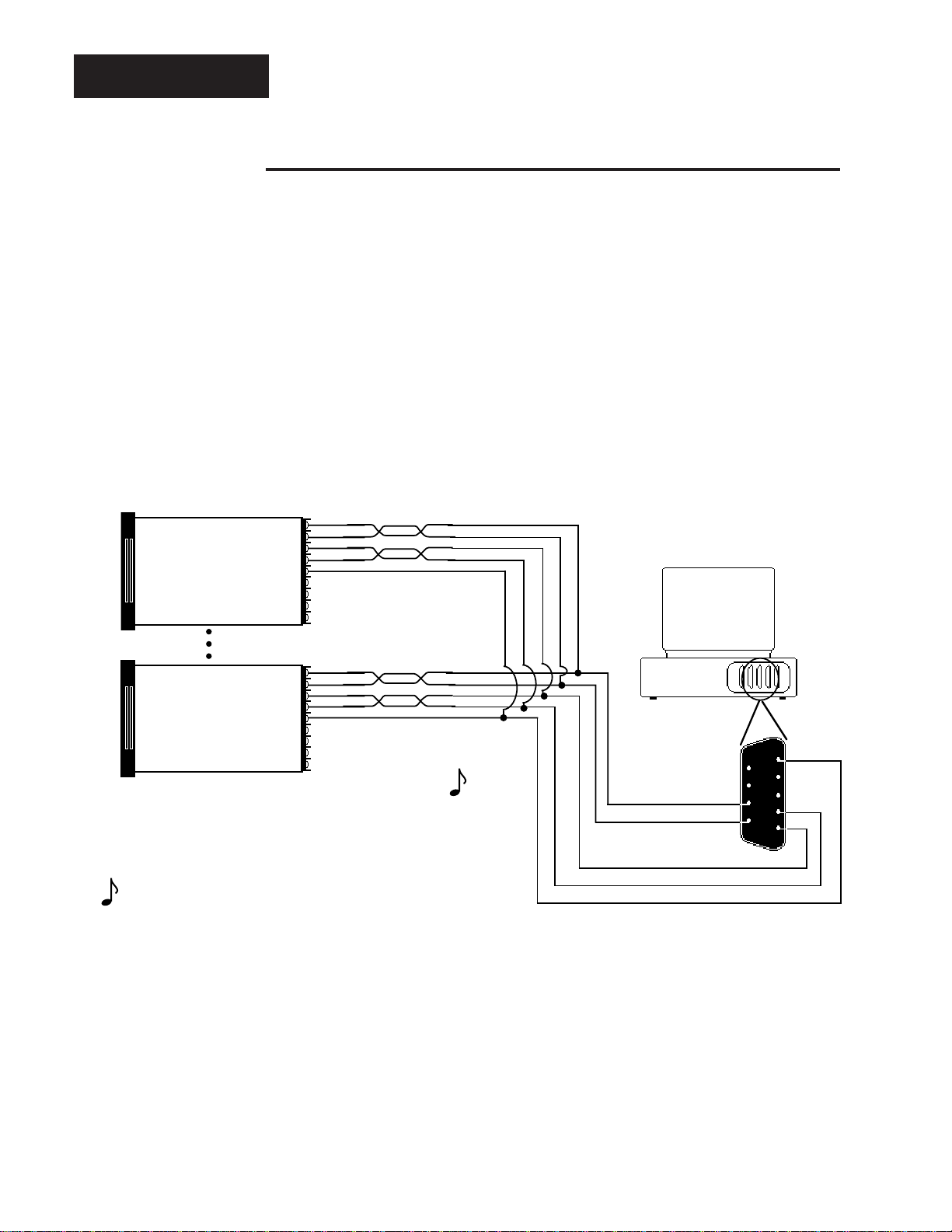
Data Logging
1
4
R
T
The data logging feature is a convenient replacement for chart recorders. Information is sent directly from the Series 945 to a serial printer, or to a computer disk file.
No computer is needed, although the 945 can be connected to a computer with a
serial port and terminal emulation software.
Data logging provides a handy reference to review process performance. The time
intervals between each entry and data printed are user selectable, with the time
display resetting every 24 hours. If there is a power interruption, the time is reset to
0.0. There are several options for the printer output. Choose from table, chart or
SPC (Statistical Process Control). See the following pages for more information on
printer outputs.
Jumper DTR, DSR, and RLSD together.
Also, jumper RTS and CTS together.
Refer to your printer's user manual.
20
Jumper to Signal Common
21
22
Signal Common
Series 945 #
23
Data Logging
Printer
Host Computer
(rear view)
2
15
3
DB-25 female connector
(located on back of printer
viewed from wire side)
DTR (Data Terminal Ready)
T
R
16
4
RTS (Request To Send)
17
5
CTS (Clear To Send)
18
6
DSR (Data Set Ready)
19
Com
7
2 0
RLSD (Received Line Signal Detector)
21
8
9
22
10
23
11
24
12
25
13
Figure 10 Data Logging
Interface Wiring
Example.
Connect the 945 to the printer as in Figure 10; this is a typical wiring example. The
connections on the printer may vary depending on the model, refer to the printer's
user manual. Enter the Setup menu by pressing the UP/DOWN keys simultaneously for three seconds. Mode through the parameters until you reach bAUd
and follow the parameter listing on Page 8. Select the appropriate data for each
prompt and enter your values in the table on Page 9. Data logging begins once
you return to the control set point.
After each line the 945 emits a carriage return. Your printer can be set up to
handle line feeds. The printer must supply a line feed (LF) following a carriage
return (CR). Refer to your printer user's manual for more information.
A data header is printed once the logging function begins. When you change the
time interval (Int) or any selected data (tag), or power is cycled, the header is
printed again. The header always remains the same, regardless of the control
configuration. The time display wraps around to 0.0 every 24 hours. If there is a
power interruption, the control will restart at 0.0 when power is restored.
How to Use Data Communications
WATLOW Series 945
21
Page 22

Data Logging
Figure 11 Table Printout
Example.
Data fields emitted are determined by the tag parameters and control configuration.
As in the following example, tag is set for PSA (Process, Set Points, and Alarm Set
Points). SET-2 is only transmitted when there is a secondary control output, and is
configured the same as the primary output. In the example below, notice A1LO was
changed to 125 resulting in an alarm condition shown as an * (asterisk) in the
PROCESS and LOW-1 columns. After a latching or non-latching alarm is cleared,
the * is removed. The ATUNE column reports the auto-tune status. START denotes the beginning of the sequence, RSTRT signifies auto-tune has been restarted, and END is displayed when complete.
Table Printout
Example: Log = On, Int = 0.5, tag = PSA
P = Process S = Set Points A = Alarm Set Points
Parameters represented:
(C1) (SP1) (SP2) (A1LO) (A1HI) (A2LO) (A2HI) (AUt)
DATE: 01-01-92
TIME PROCESS SET-1 SET-2 LOW-1 HIGH-1 LOW-2 HIGH-2 ATUNE
10:03:47 144 * 200 150 * 240 190 * 210
10:03:58 157 * 200 150 240 190 * 210 START
10:04:34 185 * 200 150 240 190 * 210
10:05:10 177 * 200 150 240 190 * 210
10:05:46 182 * 200 150 240 190 * 210
10:06:02 179 * 200 150 240 190 * 210 END
10:06:38 196 200 150 240 190 210
10:07:14 198 200 150 240 190 210
10:07:50 199 200 150 240 190 210
10:08:26 199 200 150 240 190 210
10:09:02 200 200 150 240 190 210
22
WATLOW Series 945
SPC - Statistical Process Control
SPC tracks variability to help you distinguish between natural variability (common
causes) from unnatural variability (special causes). Based upon measurements,
SPC gives you a picture of how the process is performing. By showing when
special causes are occurring, the SPC printout gives you written changes in the
process. An SPC printout is a picture of the operation. Typically, past data gives
information about what the average measurements and limits should be. These
are traditionally shown by upper and lower control limits. It also gives us a picture
of what is happening now. By comparing the process we can determine when
special, or assignable causes occur. This is advanced user-level material and
requires previous experience with Statistical Process Control (SPC).
For more information we recommend:
Juran's Quality Control Handbook
by J.M. Juran, Editor in Chief & Frank M. Gryna, Associate Editor
Hardcover, 1988 ISBN: 0-7-033176-6
Available from: McGraw Hill
1221 Avenue of the Americas
New York, NY 10020
1-800-2-MCGRAW
How to Use Data Communications
Page 23

The Difference Between Control & Specification Limits
Control limits are established on the control chart at ± 3 standard deviations (3 sigma).
They are based upon the distribution of sample averages and are calculated from the
actual performance of the process. They are typically narrower than specification limits.
Specifications are limits for individual measurements, not averages. They are based upon
engineering or customer requirements, rather than process capability. Process capability
predicts the process performance to predetermined specification limits.
When the LCL (Lower Control Limit) and UCL (Upper Control Limit) values have been
determined, the values for CPKL, CPKU, and CP are calculated and printed once on the
chart. The smaller of these two numbers will be your actual process capability or CPK.
SPC
CPKL =
If the system is too stable "variation insignificant" is printed. Your process is so stable that
even a severe shift or variation greater than ±6 sigma will still maintain a larger CPK
value. If both LSL and USL are left at their default value, they are set to the 4σ values
below and above the process mean value. Once the mean value has been calculated,
these values are used to calculate CPKL and CPKU values.
Average: The mean, or the arithmetic average, ( x ).
Control Limits: Limits on a control chart, based on actual process data, which are used
as criteria for signalling the need for action, or for judging whether a set of data does or
does not indicate a "state of statistical control."
Lower Control Limit (LCL): Control limit derived by the average minus 3 standard
deviation ( x - 3σ ).
Mean: The arithmetic average, obtained by adding all the values together and dividing by
the number of values ( x ).
Process Capability (CPKL and CPKU): A comparison of process performance with
product specifications over a period of time and while the process is in statistical control.
CPK < 0 Average value is outside the specification limits
CPK between 0 and 1 Variation is greater than the limits.
CPK = 1 Variation and the specification limits are the same
CPK between 1 and 1.33 Acceptable process control
CPK between 1.33 and 2 Good process control
CPK > 2 Excellent process control
Mean - LSL
3σ
CPKU =
USL - Mean
3σ
Sigma: The unit of standard deviation. Sigma is the greek letter "s" written σ.
SPCA (Specification limits Absolute): Represents SPC with fixed values that do not
track the set point. When SPCA is chosen, the USL range is the LSL parameter + 2 (LSL
+ 2) to the sensor's range high. Default is the sensor's default range high. The LSL range
is from the sensor's default range low to the sensor's default range high. Default is the
sensor's default range low.
SPCd (Specification limits Deviation): Represents SPC with deviation values that
follow changes to the set point. When SPCd is chosen the range for USL it will be numeric values from 1 to 99. Default is 10. The LSL range is from -1 to -99. Default is -10.
SPCn : There are no user defined values. The USL and LSL parameters are masked.
How to Use Data Communications
WATLOW Series 945
23
Page 24

Chart & SPC
e
e
Chart and SPC Printout
Example: Log = SPCA, Int = 0.1
P = Process S = Set Points
NOTE:
The time is printed
every 5th interval
(Int). The temperature variable (*) is
printed every 10th
interval.
One Int = 6 seconds.
Figure 12 Chart and SPC
Printout Example
Temperatur
*
01:00:01
01:00:31
01:01:01
01:01:31
01:02:01
01:02:31
01:03:01
01:03:31
Tim
Set Point
100°F
*
*
s
s
s
s
s
*
s
s
s
*
s
*
s
s
s
s
*
s
*
s
s
*
s
s
s
s
*
s
s
*
s
s
s
s
*
s
CP = 1.34
*
*
s
s
s
s
s
s
s
s
s
s
s
s
*
s
*
s
s
s
*
s
s
s
*
*
101
*
*
*
*
100
*
*
99
*
*
*
101
*
*
*
*
*
*
Temperature Variable
Lower Control Limit
(SPCA & SPCd only) Upper Control Limit
CPKL = 1.36 CPKU = 1.32
(SPCA & SPCd only) (SPCA & SPCd only)
90
92
Maximum Excursion Maximum Excursion
*
L
L
L
L
L
L
L
L
L
L
L
L
L
L
L
L
(Any messages concerning changes
(Any messages concerning tchanges
in he system are printed here)
in the system are printed here)
PROCESSDATE: 01-01-90
Set Point Variable
Temperature Variable
(SPCA & SPCd only)
U
U
U
U
U
U
U
U
U
U
U
U
U
U
U
U
110
110
12575
The Chart and SPC (Statistical Process Control) format are very similar. The only
difference is the SPC output displays the lower (L) and upper (U) control limit.
They are calculated based upon the mean value of the process variable, and are
derived from 30 random samples taken over the selected time base (tbS), the
mean value used is from the previous timebase samples (ex. the mean from the
first 30 samples is used to compute the control limits for the second 30 samples
and so on for every sample period. If SPCA (Specification limits Absolute or SPCd
(spec. limits Deviation) is selected then the CPKL, CP, or CPKu values will also be
printed. If the variation in the process value is too small to calculate the control
limits, L and U and the message "Variation Insignificant" are printed. If at any time
the process value exceeds the control limits during a print interval, the maximum
process excursion value will be printed (if both L and U are exceeded, both maximum values will be printed) on the next line printed. At any time the control limits
can be locked in by setting CLUP to "no" . If CLUP = no, new control limits can be
set by CLUP = YEs.
24
WATLOW Series 945
How to Use Data Communications
Page 25

Problem Cause Action
Printing all on The line feed Set the printer for a carriage
the same line. is missing. return and line feed.
The printing is Data formats are Match the Series 945 data
garbled. not compatible. format to the printers data
format using the "Data" prompt.
The printer will The printer is off line. Bring the printer on line.
not print.
The transmit and Make sure Terminal #20 and
receive lines are #22 go to the printers appropriate
reversed. receive and transmit terminals.
Error Codes
Table 7 Printer
Troubleshooting.
NAKs and Error Codes
When your message is "not acknowledged" (NAK) in RS-422A or EIA-485 with
ANSI X3.28 Protocol, you may clear ER2 code by reading it. That is, use "?"
Then try the message again; you may have made a syntax error. See the error
code listing in Table 5, Page 19.
With XON/XOFF protocol and the RS-423A interface, the 945 sends no
feedback on commands. Therefore, you may want to query the status of ER 2
after each command you send.
All communications-related error codes are ER2 error codes, that is they are
not considered cause for a shutdown of the 945 unit itself. There is always a
communications error code generated when a <NAK> character is sent under
the ANSI X3.28. With XON/XOFF flow control error codes may be generated,
but there will be no standard indication of this fact.
User Responsibility
All of the previous commands are available on all models of the Series 945 that
have communications capability. It is the responsibility of the user to refrain
from altering parameters which may not appear on the unit. (Example: AXLO
should not be set to 1 or 2 if the unit is not equipped with alarm outputs.)
How to Use Data Communications
WATLOW Series 945
25
Page 26

Index
A
ALM, 20
ANSI X3.28 "=" Command, Fig. 8, 17
ANSI X3.28 "?" Command, Fig. 9, 18
ANSI X3.28 Protocol for RS-422A & EIA-485, 3, 16
ASCII Character Set, Table 1, 10
ASCII Control Characters (Partial Set), Table 2, 10
AXHI, 20
AXLO, 20
ATMN, 20
AUT, 20
B
Baud Rate, 8
BTYP, 19
C
C1, 19
CAL, 20
Carriage Return, 13
CF, 20
Chart Printout, 25
CLUP, 9, 20
Command, "?", 19
Command, "=", 20
Command Data & Responses, Partial Set for "?", 19
Command Data "=" and "?", Table 6, 20
Command List, 12
Communications
Parameters, 8
Switch Selection, 7
Wiring, 3
Connecting the Control and the Computer, 7
CTX, 20
D
Data Parameters, 8
Data Link Escape (DLE), 17
Data Logging, 22
Data Rules, 11
DB, 20
DEC, 20
Device Address, 16
E
EIA-485, 3, 6
End of Text (ETX), 13
End of Transmission (EOT), 17
ERR, 19
ER2, 19
Example Format, 12
F
Flow Control, 13
G
General Message Syntax, 11
H
How to Use Data Comms. with the Series 945, 3
HYSX, 20
26
WATLOW Series 945
I
Identification Number, 16
IN, 19
INDC, 20
INT, 20
Interface Wiring,
RS-422A, Fig. 1, 4
RS-423A, Fig. 2, 5
EIA-485, Fig. 3, 6
L
LATX, 21
LOC, 21
LOG, 8, 21, 22
L-R, 21
LSL, 21
M
MAN, 21
MDL, 19
Message Syntax, 11
MODE, 19
Multidrop, 3
N
NAKs and Error Codes, 26
Network connections, 7
O
OT
X, 21
P
X, 21
PB
Protocol,
XON-XOFF, 13
ANSI X3.28, 16
R
RA
X, 21
REX, 21
RS-422A, 3, 4
RS-423A, 3, 5
RSP, 19, 21
RH, 21
RL, 21
S
Setup Menu, 8
SPC, 23
SP
X, 21
Space, 12
Starting Communications in ANSI X3.28 Protocol, 16
Start of Text (STX), 13
Stopping Communications in ANSI X3.28 Protocol, 17
T
Table Printout, 23
TAG, 21
tbS, 20
Two Hardware Interfaces & Protocols, 3
U
USL, 21
W
Wiring Data Communications, 4 - 6
X
XON/XOFF
"=" Command Example, Fig. 6, 14
"?" Command Example, Fig. 7, 15
How to Use Data Communications
Page 27

Notes
How to Use Data Communications
WATLOW Series 945
27
Page 28

28
Series 945 Data Communications User's Manual
Watlow Controls, 1241 Bundy Blvd., Winona, MN 55987, Phone: 507/454-5300, Fax: 507/452-4507
WATLOW Series 945
How to Use Data Communications
 Loading...