

Page 1
Order toll-free in the U.S. 24 hours, 7 A.M. Monday to midnight Friday: 877-877-BBOX
FREE technical support, 24 hours a day, 7 days a week: Call 724-746-5500 or fax 724-746-0746
Mail order: Black Box Corporation, 1000 Park Drive, Lawrence, PA 15055-1018
Web site: www.blackbox.com • E-mail: info@blackbox.com
CUSTOMER
SUPPORT
INFORMATION
OCTOBER 1994
MX219A
MX215C, MX218C
MX222C, MX223C
MX224, MX226C
MX228C, RM220
Multiserver 5000
EXE
MULTISERVER 5000
Page 2

Multiserver 5000
1
Multiserver 5000
Multiserver 5000 CommPak
MS5 Expansion Module Sync/Async
MS1 Expansion Module—Async only
MS1 Expansion Module—12 Async—RJ-45
MS1 Expansion Module—12 Async—RJ-45 w/Line Drivers
MS1 V.35 Converter/DCE
MS1 X.21 (V.11) Converter
MS1 Rackmount Kit
Installation and Operation Manual
Warning
Access to the interior of the unit for such purposes as replacing fuses,
or any other maintenance-type of procedure, must be performed only by
a qualified technician. Before any such work is performed, the power
supply must be disconnected from the source of power to avoid any
possibility of electrical shock.
Page 3

Multiserver 5000
2
FEDERAL COMMUNICATIONS COMMISSION
RADIO FREQUENCY INTERFERENCE STATEMENT
This equipment generates, uses, and can radiate radio frequency energy and if not installed an used
properly, that is, in strict accordance with the manufacturer's instructions, may cause interference to radio
communication. It has been tested and found to comply with the limits for a Class A computing device in
accordance with the specifications in Subpart J of Part 15 of FCC Rules, which are designed to provide
reasonable protection against such interference when the equipment is operated in a commercial
environment. Operation of this equipment in a residential area is likely to cause interference, in which case
the user at his own expense will be required to take whatever measures may be required to correct the
interference.
Changes or modifications not expressly approved by the party responsible for compliance could void the
user's authority to operate the equipment.
This digital apparatus does not exceed the Class A limits for Radio noise emission from digital apparatus set out in the
Radio Interference Regulation of Industry Canada.
Le présent appareil numérique n'émet pas de bruits radioélectriques dépassant les limites applicables aux appareils
numériques de la classe A prescrites dans le Règlement sur le brouillage radioélectrique édicté par Industrie Canada.
TRADEMARKS
HP
®
is a registered trademark of Hewlett-Packard
Hewlett-Packard
®
is a registered trademark of Hewlett-Packard
HP3000™is a trademark of Hewlett-Packard
IBM
®
is a registered trademark of IBM Corporation
AS/400
®
is a registered trademark of IBM Corporation
MICOM®is a registered trademark of Nortel Networks.
Tandem®is a registered trademark of Tandem Computers Incorporated
WANG
®
is a registered trademark of Gentronics NV.
Any other trademarks mentioned in this manual are acknowledged to be the property of the trademark owners.
Page 4

Table of Contents
3
1. Specifications
Multiserver 5000 (Base Unit) ..................................................................................................13
Expansion Modules..................................................................................................................15
MS1 Voice/Fax Cards ..............................................................................................................16
MS1 56K CSU/DSU Module ...................................................................................................18
MS RLB Module.......................................................................................................................18
MS1 NMS Module....................................................................................................................19
MS1 V.35 Converter/DCE .......................................................................................................19
X.21 Converter/DCE...............................................................................................................19
2. Introduction
2.1 The Multiserver 5000 (Base Unit) ...................................................................................20
2.2 Feeder Muxes ....................................................................................................................21
2.3 The Commpak ..................................................................................................................23
2.4 Expansion Modules...........................................................................................................23
2.5 MS1 Voice/Fax Card.........................................................................................................23
2.6 MS1 56K CSU/DSU Module (MT150C) ........................................................................23
2.7 MS RLB Module (MX229A).............................................................................................23
2.8 MS1 NMS Module (MX227C)..........................................................................................24
2.9 MS1 V.35 Converter/DCE (MX226)................................................................................24
2.10 MS1 X.21 (V.11) Converter (MX228C).........................................................................24
2.11 MS1 Rackmount Kit (RM220)........................................................................................24
2.12 Documentation ...............................................................................................................24
2.13 Manual Text Conventions...............................................................................................25
3. Network Design and Topologies
3.1 Initial Considerations .......................................................................................................26
3.2 Worksheets for the Network.............................................................................................27
3.3 Nodes and Hubs ...............................................................................................................27
3.4 Syntax for Node Numbers and IDs ..................................................................................27
Table of Contents
Page 5

Multiserver 5000
4
3.5 Default Node Numbers and Node IDs ............................................................................27
3.6 Examples of Network Designs..........................................................................................29
Single Link Point-to-Point.........................................................................................................29
Dual Link Point-to-Point...........................................................................................................30
String..........................................................................................................................................31
Star .............................................................................................................................................32
Distributed Star .........................................................................................................................33
4.0 Base-Unit Installation
4.1 Check Contents.................................................................................................................34
4.2 Plan the Location Based on the Physical Description and Requirements ....................34
4.2 CommPak Cartridge Installation and Removal ..............................................................35
Installing the CommPak Cartridge ..........................................................................................35
Removing the CommPak Cartridge .........................................................................................35
4.3 Power Up the Unit ............................................................................................................35
4.4 LCD Display.......................................................................................................................36
4.5 Checking the CCM Indicators..........................................................................................36
4.6 Identify the Module Locations and Channel Numbers..................................................37
Module Location and Nomenclature ......................................................................................37
Channel Location and Nomenclature.....................................................................................38
5. Module Installation
5.1 Module Stacking Order ....................................................................................................40
5.2 Module-Location Switch Settings.....................................................................................41
5.3 Inter-Module Stacking Connectors..................................................................................42
5.4 Blank Back Panel...............................................................................................................43
5.5 Disassembly Procedures....................................................................................................43
5.5.1 Unplug the Multiserver...................................................................................................43
5.5.2 Remove the Cover ...........................................................................................................44
5.5.3 Remove Blank Back Panels.............................................................................................45
5.5.4 Remove Spacers...............................................................................................................45
5.5.5 Disassembly Considerations............................................................................................46
5.5.6 Removing a Channel Expansion Module (CEM), Voice/Fax Card,
or CSU/DSU Module.....................................................................................................46
Table of Contents (continued)
Page 6

Table of Contents (continued)
Table of Contents
5
5.5.7 Removing the CCM.........................................................................................................46
5.6 Installation Procedures.....................................................................................................47
5.6.1 Install the Spacers ...........................................................................................................47
5.6.2 Install the CCM................................................................................................................47
5.6.3 Install Channel Expansion Modules ..............................................................................48
5.6.4 Remaining Spacers..........................................................................................................49
5.6.5 Installing Blank Back Panels...........................................................................................49
5.6.6 Put the Cover Back On ...................................................................................................50
5.8 Converters (Optional Equipment) ..................................................................................51
Installing Converters .................................................................................................................51
Removing Converters................................................................................................................51
6. Getting Started
6.1 Multiserver Base Unit Location .......................................................................................52
6.2 Connecting an ASCII Terminal........................................................................................52
6.3 The Command Facility .....................................................................................................53
Access the Command Facility via the Command Mode using ^X <break> ...........................53
Access the Command Facility via $CMD..................................................................................54
Exiting the Command Facility..................................................................................................54
6.4 Reset Defaults....................................................................................................................55
6.6 Name the Local Node.......................................................................................................56
Command Facility Configuration.............................................................................................56
LCD/Keypad Configuration.....................................................................................................57
NMS Switch Configuration .......................................................................................................57
6.6 Quick Setup.......................................................................................................................58
Can You Do a Quick Setup?......................................................................................................58
Preliminary Steps.......................................................................................................................58
The Interconnect Link..............................................................................................................58
The Force-Connection..............................................................................................................59
7. Bench Configuration and Testing
7.1 Overview ............................................................................................................................60
Key to Examples and Illustrations ............................................................................................60
7.2 Using CSU/DSUs with the Interconnect Link................................................................62
Internal CSU/DSU to Internal CSU/DSU..............................................................................62
Page 7

Multiserver 5000
6
External CSU/DSU to Internal CSU/DSU .............................................................................62
External CSU/DSU to External CSU/DSU.............................................................................62
CCM Indicators .........................................................................................................................62
Final Installation........................................................................................................................62
7.3 Using Modems with the Interconnect Link ....................................................................63
7.4 The Sync Data Channel ....................................................................................................64
7.5 Testing Asynchronous Data Channels .............................................................................66
Async Channels on the Local Node .........................................................................................66
Async Channels Across the Link...............................................................................................66
Configuration ............................................................................................................................66
7.6 Testing the RLB Module...................................................................................................68
ThinNet......................................................................................................................................68
ThickNet, 10BASE-T, and Fiber ...............................................................................................68
Further Configuration ..............................................................................................................68
7.7 Voice/Fax Channels..........................................................................................................69
Force-Connected Voice Channels............................................................................................69
Connect the Phone to the Multiserver ....................................................................................69
The Test .....................................................................................................................................69
8. Link Configuration
8.1 Types of Links....................................................................................................................70
8.2 Avoid Node Duplication...................................................................................................70
8.3 Assign a Port for each Link ..............................................................................................70
8.4 Port Configuration............................................................................................................71
8.5 The Interconnect Link .....................................................................................................72
Port Configuration for the Interconnect Link........................................................................72
Install the Interconnect Link....................................................................................................72
Connecting Multiserver Units back-to-back.............................................................................73
Remote Multiserver Configuration ..........................................................................................73
8.6 The Mux Link....................................................................................................................75
Port Configuration for the Mux Link ......................................................................................75
Install the Mux Link..................................................................................................................75
Feeder Mux Node IDs...............................................................................................................76
8.7 The X.21 Link ...................................................................................................................77
Table of Contents (continued)
Page 8

Table of Contents (continued)
Table of Contents
7
Introduction to X.21 .................................................................................................................77
Port Configuration for the X.21 Link ......................................................................................77
Configuration of X.21 Link Parameters ..................................................................................77
Install the X.21 Link..................................................................................................................80
X.21 Feeder Mux Node IDs ......................................................................................................80
X.21 Channels ...........................................................................................................................80
X.21 Calls ...................................................................................................................................80
8.8 Review Link Configuration...............................................................................................81
9. Data-Channel Configuration
9.1 Port Configuration............................................................................................................82
9.2 Synchronous Channels .....................................................................................................83
Protocol Menu...........................................................................................................................83
Sync Channel Parameters .........................................................................................................83
Control Signals ..........................................................................................................................85
9.3 Asynchronous Channels ...................................................................................................93
Async Channel Menu ................................................................................................................93
Channel Characteristics ............................................................................................................94
Channel Features ......................................................................................................................98
Extended Features...................................................................................................................101
9.4 Copy Channel Parameters..............................................................................................102
9.5 Review Data-Channel Configuration .............................................................................103
Reviewing Sync-Channel Configuration ................................................................................103
Reviewing Async-Channel Configuration ..............................................................................104
9.6 Connecting Data Channel Cables..................................................................................105
10. Switching Configuration
10.1 Switching Control .........................................................................................................106
10.2 Point-to-Point Dedicated (Force Connect All) ...........................................................109
10.3 Force-Connecting a Range ...........................................................................................110
Example of Force-Connecting a Range .................................................................................111
10.4 Synchronous Connections............................................................................................111
10.5 Asynchronous Connections..........................................................................................112
Async Force-Connections........................................................................................................112
Page 9

Multiserver 5000
8
Fixed Destination Connection ...............................................................................................112
Class Connections ...................................................................................................................112
Node/Class Connection .........................................................................................................113
Matrix Connection ..................................................................................................................113
10.6 Matching Capability for Asynchronous Channels.......................................................114
10.7 Asynchronous-Channel Switching Parameters............................................................115
10.8 Classes ............................................................................................................................118
What is a Switching Class?.......................................................................................................118
Example of a Switching Class .................................................................................................120
Planning a Class.......................................................................................................................120
Configuring a Class .................................................................................................................120
Review Class Configuration ....................................................................................................123
Review Class Messages.............................................................................................................123
10.9 Connect Protocol Details..............................................................................................124
Dedicated Protocol..................................................................................................................124
DTR Protocol...........................................................................................................................124
Auto (Answer) Protocol..........................................................................................................126
10.10 Port Contention/Queueing .......................................................................................126
10.11 X.21 Switching Considerations ..................................................................................127
10.12 Review Switching Configuration for an Async Channel ...........................................129
11. Administration
11.1 Reset...............................................................................................................................130
Keypad Reset............................................................................................................................130
Command Facility Reset .........................................................................................................131
11.2 The Command Mode ...................................................................................................133
Entering the Command Mode .............................................................................................................133
Exiting the Command Mode..................................................................................................133
11.3 Configuring the Command Facility .............................................................................135
11.4 Messages ........................................................................................................................140
Alarm Messages .......................................................................................................................140
Event Messages ........................................................................................................................140
Class Messages .........................................................................................................................140
Broadcast Messages .................................................................................................................140
Table of Contents (continued)
Page 10

Table of Contents
9
Dialog Messages.......................................................................................................................141
11.5 Network Security ...........................................................................................................144
Passwords .................................................................................................................................141
Lock-Out Configuration .........................................................................................................147
11.6 Status/Statistics .............................................................................................................148
11.7 Link Administration......................................................................................................154
Reset.........................................................................................................................................154
Status/Statistics........................................................................................................................154
Channel Priority Over the Link..............................................................................................154
11.8 Channel Administration...............................................................................................154
11.9 Switching Administration .............................................................................................155
12. Diagnostics
12.1 Self-Test..........................................................................................................................157
12.2 Terminate Test...............................................................................................................157
12.3 Async Channel Loopback in the Command Mode.....................................................157
Local Echo ...............................................................................................................................157
Remote Echo ...........................................................................................................................157
Local Fox .................................................................................................................................158
Remote Fox..............................................................................................................................158
12.4 System Diagnostics in the Command Facility..............................................................159
Remote Composite Loopback ................................................................................................159
Link Channel Loopback .........................................................................................................159
Async Channel Output............................................................................................................160
Sync Channel Loopback .........................................................................................................161
Voice/Fax Tests.......................................................................................................................162
Integral Device Tests ...............................................................................................................162
LED Test ..................................................................................................................................162
Memory Dump ........................................................................................................................162
12.5 Testing the Network ......................................................................................................163
Table of Contents (continued)
Page 11

Multiserver 5000
10
13. LCD/Keypad
13.1 General LCD/Keypad Information .............................................................................165
LCD Blinking Backlight ..........................................................................................................166
Keypad Reset............................................................................................................................166
LCD/Keypad Password Protection.........................................................................................166
Timeouts ..................................................................................................................................166
Channel Numbers ...................................................................................................................166
13.2 Banner Message Display ...............................................................................................168
Configuring the Banner Message...........................................................................................168
The Banner Message Menu ....................................................................................................169
13.3 Review System Message Log .........................................................................................169
13.4 Menu Functions ............................................................................................................169
13.5 Administration ..............................................................................................................169
System ......................................................................................................................................169
Voice/Fax ................................................................................................................................169
Busy Mode................................................................................................................................170
Local Node ID .........................................................................................................................170
13.6 Diagnostics.....................................................................................................................171
System ......................................................................................................................................171
Voice/Fax ................................................................................................................................172
Integral Devices .......................................................................................................................174
13.7 Configuration................................................................................................................174
Appendix A: Worksheets
Worksheet for Planning Node Numbers and Node IDs......................................................176
Worksheet for Recording Optional Module Locations and their Connectors ..................177
Synchronous Protocol and Channel Worksheet .................................................................178
Asynchronous Channel Characteristics Worksheet ............................................................180
Asynchronous Channel Features Worksheet .......................................................................182
Asynchronous Channel Extended Features Worksheet .....................................................184
Record of Asynchronous Classes ..........................................................................................185
Switching Parameters Worksheet..........................................................................................186
Command Facility Paraments Worksheet ............................................................................187
Table of Contents (continued)
Page 12

Table of Contents
11
Display Messages Worksheet..................................................................................................188
Voice/Fax Parameters Worksheet.........................................................................................189
Record of Passwords ..............................................................................................................190
Appendix B: Cabling Diagrams
Cabling for the CCM and 6-Channel CEMs .........................................................................192
Cabling for the 12-Channel CEM ........................................................................................198
Cabling for the 12-Channel CEM with Line Drivers............................................................202
Cabling for the MS1 56K CSU/DSU Module.......................................................................204
Cabling for the NMS Module................................................................................................205
Cabling for Converters ..........................................................................................................206
Cabling for use with Tandem ................................................................................................210
Appendix C: Defaults
System Administration...........................................................................................................211
Multiserver and Feeder Mux Default Node Numbers and IDs ............................................211
Port Configuration ..................................................................................................................211
Command Facility Parameters................................................................................................212
Dialog Messages.......................................................................................................................212
Asynchronous Channel Configuration.................................................................................213
Channel Characteristics ..........................................................................................................213
Channel Features ....................................................................................................................213
Extended Features...................................................................................................................213
Switching Parameters..............................................................................................................213
Synchronous Channel Characteristics..................................................................................214
Channel Characteristics ..........................................................................................................214
DLC ..........................................................................................................................................214
ASCII Bisync and EBCDIC Bisync ..........................................................................................214
RTS/CTS .................................................................................................................................215
Sync-Pad ...................................................................................................................................215
H-P Sync...................................................................................................................................216
MICOM DLC ...........................................................................................................................216
MICOM Voice..........................................................................................................................216
TDM .........................................................................................................................................217
Table of Contents (continued)
Page 13

Multiserver 5000
12
Fast Packet ...............................................................................................................................217
Voice/Fax Module .................................................................................................................218
KTS Interface...........................................................................................................................218
E&M Interface .........................................................................................................................218
OPX Interface..........................................................................................................................218
Voice/Fax Node Parameters ..................................................................................................219
Voice/Fax Switching Parameters ...........................................................................................219
NMS Module ..........................................................................................................................220
Command Port ........................................................................................................................220
Log (Printer) Port ...................................................................................................................220
Appendix D: Messages
Screen Display Messages........................................................................................................221
LCD Messages.........................................................................................................................234
Appendix E: Indicators
CCM Indicators ......................................................................................................................239
CEM Indicators ......................................................................................................................241
Voice/Fax Indicators .............................................................................................................242
CSU/DSU Indicators .............................................................................................................244
Appendix F: Device Applications
Extended Wang Support Feature (WANGX).......................................................................245
Tandem ...................................................................................................................................245
HP ENQ/ACK........................................................................................................................245
Tail-Ending Mode (Dial-Up Modem Operation).................................................................246
Appendix G: Rackmount Installation .........................................................................................247
Appendix H: Additional Information.........................................................................................249
Glossary .............................................................................................................................................252
Table of Contents (continued)
Page 14

CHAPTER 1: Specifications
13
Multiserver 5000 (Base Unit)
MX219A
Performance Specifications
Multiplexor Technique — Fast Packet Multiplexing
Capacity —
Data Channels: up to 5 (Ports A2 to A6)
Feeder Mux Links: up to 5 (Ports A1 to A5)
Interconnect Links: up to 3 (Ports A1 to A3)
Speed —
Data Channel: see Async Channel
Characteristics and Sync Channel
Characteristics.
Feeder Mux Link: up to 19.2 Kbps
Interconnect Link: up to 72 Kbps
Data Format —
Data Channel: sync or async
Feeder Mux Link: Sync, internal/external
clocking, full-duplex
Interconnect Link: Sync, internal/external
clocking, full-duplex
Flow Control — CTS/DTR and X-ON/X-OFF
(configurable per channel end); HP ENQ/ACK,
Tandem, WANG (configurable by channel)
Diagnostics —
Data Channel: Local/remote channel
loopback, local/remote channel output, local
sync channel loopback
Feeder Mux Link: Local and remote composite
loopback, local system loopback
Interconnect Link: Local and remote composite
loopback, local system loopback
Command Facility — Menu driven. Provides
message broadcast, dynamic channel
configuration, centralized troubleshooting,
alarm messages, and periodic reports.
Status Displays — System status and port activity
indicator lights, 80-character LCD on the front
panel.
Physical Specifications
Expansion — up to 4 modules (in locations B, C, D,
and E) and the NMS module (underneath the
CCM).
Keypad — 5 button
Indicators — 80-character front-panel LCD and
Communications Control Module LEDs:
AT - Power On
BO - Buffer Overflow
A1 to A6 - Port Activity
Interface — RS-232, V.24/V.28, DCE
Connectors — (6) DB25 (female)
Power — 90-265 Vac, 3 to 1.5 amps, 47 to 63 Hz,
135 watts maximum
Distance to power source — Do not exceed 6 feet
(1.8 m); do not use extension cords
Size — 6.5"H x 17.5"W x 12.5"D
(16.5 x 44.5 x 31.8 cm)
Weight — 22 lb. (10 kg)
Temperature —
Operating: 32° to 114°F (0° to 45°C);
Storage: -40° to +158°F (-40° to +70°C)
Humidity —
Operating: 10% to 90% relative humidity
(noncondensing);
Storage: 0 to 95% relative humidity
(noncondensing)
Lithium Battery — Located on the base module,
the battery supplies power to CMOS RAM for an
accumulated power down life of eight years.
Usable life of the battery is ten years (not
rechargeable)
Agency Compliance —
FCC: Part 15, Class A; Part 68 (voice, modem, ISU)
UL: 1950 CSA Standard C22.2 NO. 950 M-89
BABT
FTZ 1046 Level B
EN60950/VDE 0805
1. Specifications
Page 15

Multiserver 5000
14
Async Channel Characteristics
Capacity — up to 41
Speed — 50 to 38,400 bps
Configuration — DCE
ABR — to 19.2 Kbps
Parity — Odd, Even, Mark, Space, None
Stop Bits — 1, 1.5, 2
Characters — 5 to 8 bits/character plus parity (code
levels 5 through 9)
Burst Rate — 422 Kbps (half-duplex over 56 Kbps
composite)
Error Control — Full-duplex, automatic request for
repetition (ARQ), with Cyclic Redundancy
Check (CRC), and selective reject. Proprietary
algorithm.
Classes — 64
Delay Characteristics — Average delay through the
Multiserver is two character times, plus the
transmission delay through the Multiserver
system. Although transmission delay is normally
very low, terminal users operating with an
echoplex system will experience this delay twice;
that is, once inbound to the computer and once
on echo outbound to the terminal. This delay is
not normally noticeable with speeds of 1200 bps
and above, but may be noticeable with speeds of
300 bps or less.
Sync Channel Characteristics
Capacity — up to 10
Speed —
External clocking: 1.2 to 38.4 Kbps
Internal clocking:
DLC: 1.2 to 38.4 Kbps;
ASCII Bisync: 1.2 to 38.4 Kbps;
H-P Sync: 1.2 to 38.4 Kbps;
RTS/CTS: 1.2 to 38.4 Kbps;
Sync-Pad: 1.2 to 38.4 Kbps;
EBCDIC Bisync: 1.2 to 38.4 Kbps;
Micom DLC 1.2 to 19.2 Kbps;
Micom Voice: 9.6 to 14.4 Kbps;
Fast Packet: 1.2 to 56 Kbps;
TDM: 1.2 to 48 Kbps.
Configuration — DCE
Protocols — DLC, ASCII Bisync, EBCDIC Bisync, H-
P Sync, RTS/CTS, Sync-Pad, MICOM DLC,
MICOM Voice, Fast Packet, and TDM
Multiserver 5000 (continued)
Page 16

CHAPTER 1: Specifications
15
Expansion Modules
MS5 Expansion Module Sync/Async
MX215C
Connectors — (6) DB25 (female)
Interface — RS-232, V.24/V.28
Transmission Mode — Serial async; full-duplex
Configuration — DCE
Speed —
Async: 50 to 38,400 bps
Sync: Protocol Dependent
(see Sync Channel Characteristics)
MS1 Expansion Module—Async Only
MX222C
Connectors — (6) DB25 (female)
Interface — RS-232, V.24/V.28
Transmission Mode — Serial async; full-duplex
Configuration — DCE
Speed — 50 to 38,400 bps
MS1 Expansion Module—12 Async—RJ-45
MX223C
Connectors — (12) RJ-45 (female)
Interface — RS-232, V.24/V.28
Transmission Mode — Serial async; full-duplex
Configuration — DCE
Speed — 50 to 38,400 bps
MS1 Expansion Module—12 Async—
RJ-45 w/Line Drivers
MX224C
Connectors — (12) RJ-45 (female)
Interface — RS-422; RS-423
Transmission Mode — Serial async; full-duplex
Configuration — DCE
Speed — 50 to 38,400 bps
Page 17

Multiserver 5000
16
MS1 Voice/Fax Cards
MX225C-1 AND MX225C-2
General Specifications
Channels per Voice/Fax Card —
MX225C-1: One channel
MX225C-2: Two channels
Signals Supported — Analog voice and Group III
fascimile (fax)
Telephone Interfaces —
PBX tie trunk: E&M Types I through V,
2-wire or 4-wire;
PBX station or Central Office PSTN: OPX
Loop Start, 2-wire;
Key telephone systems, telephone set or PBX
CO Trunk: KTS Loop Start, 2-wire;
Compatible Connections: OPX to KTS;
E&M to E&M; E&M to KTS; KTS to KTS (ringdown)
Interface Connectors — RJ-11 modular jack for
KTS- and OPX-type interfaces; 8-pin terminal
block for KTS, OPX, and E&M type interfaces
Indicators per Channel —
OK - OK
LO - Local Off-Hook
RO - Remote Off-Hook
LS - Local Speech
RS - Remote Speech
TM - Test
Diagnostics — Self-Test, Loopback, and Input Level
Display
Analog Specifications
Insertion Loss — 2 dB nominal @ 1000 Hz (End-to-
End)
Audio Levels —
Input/Output Levels: 0 dBm maximum
Adjustable Range: +28 dB to –28 dB in steps of
1 dB
Frequency Response — 300 Hz to 3000 Hz @ +1.5
dB/-2 dB
Idle Channel Noise — ≤22 dBrnC
Non-Linear Distortion — Second Harmonic ≥40 dB
below Signal; (4 tone method): Third Harmonic
≥40 dB below Signal
Signal to Noise Ratio — ≥37 dB
Input Impedances —
E&M 4-wire, E&M 2-wire, KTS 2-wire: 600 Ω,
±10 percent, balanced
OPX 2-wire: 600 Ω nominal
Return Loss —
Echo Return Loss: ≥20 dB
Singing Return Loss:
Low: ≥14 dB
High: ≥14 dB
Longitudinal Balance —
200 to 1000 Hz: ≥58 dB
1000 to 3000 Hz: ≥53 dB
Echo Canceling — ≤4 milliseconds (≤150 miles)
Echo Suppression — ≥ 35 dB
Crosstalk (near/far end) —
E&M 4 wire: ≥75 dB transmit to receive;
between channels: ≥75 dB
Page 18

CHAPTER 1: Specifications
17
Signaling Specifications
Formats —
Dial Pulse: ≤3% distortion @ 10 pulses per
second
Dual Tone Multifreq: ≤1% distortion
Steady DC (E&M): Types I, II, III, IV, and V
Single Frequency: 2280 Hz (AC15) on E&M 4
wire interface only
Pulsed DC (RonTron): E&M interface only
NOTE: Both ends must use the same signaling
format
KTS Interface —
Loop Range: 400 Ω (2000 feet on 24 AWG wire
pair)
Ringing Source: 25 or 50 Hz ±2 Hz, 40 Vrms
into 2 ringers
Ring Cadence: Repeated ring (matches ringing
cadence from remote voice/fax channel),
interrupted ring 2/4 (2 seconds on, 4 seconds
off), or interrupted ring 2 1/2 (ring two times
for 0.4 second separated by .02 second, and
then be off for two seconds)
OPX Interface —
Loop Range: 900 Ω (6500 feet on 24 AWG wire
pair)
Ringing Detection: 19 to 33 Hz at
40 to 90 Vrms
E&M Interface —
Loop Range: 400 Ω (2000 feet on 24 AWG wire
pair)
Digital Specifications
Channel Digitizing Rates — 4.8, 6.4, 7.2, 8, 9.6, 12,
14, and 16 Kbps
Fascimile Rates — Group III fax at 9.6, 7.2, 4.8, and
2.4 Kbps, not to exceed channel digitizing rate
Link Error Rate —
Circuit Degradation @ ≤1 bit in 100,000
Circuit Unacceptable @ ≤1 bit in 10,000
Mean One-Way Propagation Time —
≤180 ms for voice (excluding link propagation)
≤253 ms for fax (excluding link propagation)
MS1 Voice/Fax Cards (continued)
MX225C-1 AND MX225C-2
Page 19

Multiserver 5000
18
MS1 56K CSU/DSU Module
MT150C
Network Application — 4-wire DDS interface to
AT&T Digital Data Service network (or
equivalent)
Data Rate — 56 Kbps
Connectors — RJ-48S (USOC) 8-pin modular jack
Transmission Mode — Synchronous; full-duplex
Loop Range — 15,000 feet (4572 m) over 26 AWG
wire
Output Signal — Pulse amplitude 1.4 to 2.1 V (135-
ohm load)
Operating Modes — Data, Idle, Out-of-Service, Test
Timing — Network-derived (internal crystal)
Clocking — Internal/External
Diagnostics — Local Loopback, Digital Loopback,
End-to-End Test Pattern, Self-Test, Telco CSU
and DSU tests
Indicators —
LL - Local Loop
RT - Remote Test
SI - Signal Indicator
RD - Receive Data
TD - Transmit Data
Certifications — FCC Part 68; FCC 15, Subpart J,
Class A; UL
®
and CSA
MS RLB Module
MX229A
Connectors — 15-pin AUI connector or BNC
connector
Indicators — Bridge LEDs:
AT - Power On
LA - LAN Activity
BA - Bridge Activity
IB - Input Buffer
OB - Output Buffer
Protocols Supported — All LAN protocols,
including use of oversize packets in Novell
NetWare.
Data Compression — All LAN data compressed up
to 6:1. TCP/IP and LAT headers compressed
up to 10:1.
Filters — Automatic filtering on destination
address. Optional filters include broadcast,
multicast, source address, protocol type, and
pattern match.
Spanning Tree — IEEE 802.1D compliant.
Compatible with all 802.1D compliant bridges.
Filtering Performance — 10,000 packets per second
(64-byte packets) maximum.
Forwarding Performance — 300 packets per seond
maximum.
Management Interface — Command Facility of the
local or remote Multiserver Bridge 1000. From
LAN via LAT or TELNET connection. SNMP
agent with public domain MIB II (monitor
only).
Page 20

CHAPTER 1: Specifications
19
MS1 NMS Module
MX227C
Command and Printer Ports:
Connector — DB25 (female)
Interface — RS-232/V.24/V.28
Transmission Mode — Serial async
Data Rates — Up to 19.2 Kbps
Alarm Relay Connector — 4-position terminal block
MS1 V.35 Converter/DCE
MX226
Converter — RS-232 to V.35
Connectors —
To Central Control Module: DB25 (male)
To V.35 Connector: DB25 (female)
Cable (included) — 5-foot DB25 (male) to
34-pin M-block (male)
X.21 Converter/DCE
MX228C
Converter — RS-232 to X.21
Connectors —
To Central Control Module: DB25 (male)
To X.21 Connector: DB15 (male)
Cable (not included) — 5-foot DB15 (female) to
DB15 (male) (EVNX21-003M-MF)
Page 21
2.1 The Multiserver 5000 (Base Unit)
The Multiserver 5000 is a communications-network
multiplexor. It integrates data, voice, fax, and
external LAN bridge network traffic for
transmission over a single leased line, eliminating
the need for individual telephone lines and
Multiserver 5000
20
separate pieces of equipment to transmit these four
different types of signals.
The base unit (MX219A) comes with the
Communications Control Module (CCM), universal
power supply, an AC power cord, and this manual.
The CCM has six ports. You can configure up to
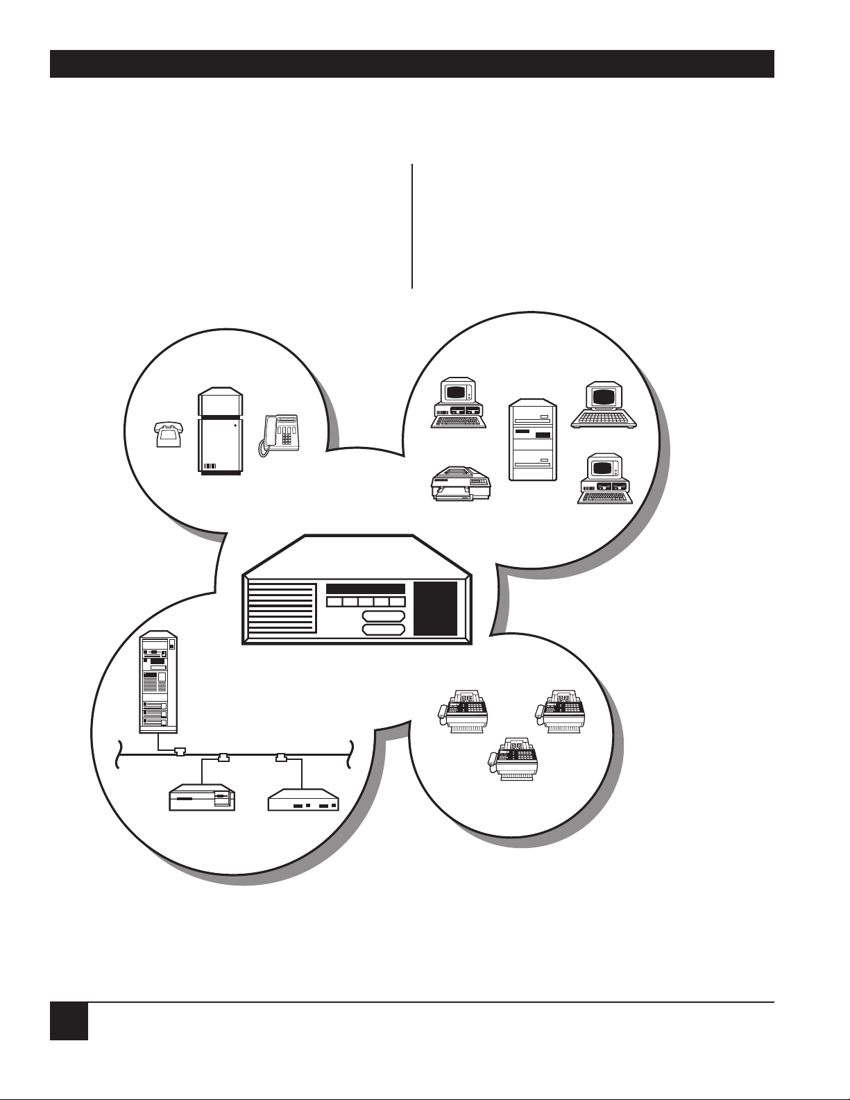
Figure 2-1. The Multiserver acts as your communication hub.
Different types of data are integrated and then transmitted over one link.
2. Introduction
Voice
Data
Fax
LAN
TERMINAL
SERVER
BRIDGE
Page 22
CHAPTER 2: Introduction
21
three (3) high-speed interconnect links (a
Multiserver-to-Multiserver connection) in ports A1
to A3, five (5) mux links (a Multiserver-to-feedermux connection) in ports A1 to A5, or five (5) data
input/output channels in ports A2 to A6.
The high-speed interconnect or composite
channels and the mux channels support RS-232C,
V.24, and V.28 interfaces. Data-transmission speeds
can be from 1200 bps to 72 Kbps on interconnect
links or up to 19.2 Kbps on mux links. Operation is
serial synchronous, full-duplex, with internal or
external clocking.
The five I/O ports on the CCM present themselves
as DCE. They can be set up for either synchro-nous
or asynchronous data transmission.
In addition to the CCM, there are expansion and
access modules, detailed below, that let you
customize your network to your specific data
communication needs.
2.2 Feeder Muxes
The Multiserver 5000 can support up to five (5)
feeder muxes. Each feeder mux can support both
async data channels and voice/fax channels. The
following multiplexors are link-compatible with a
Multiserver:
• Communication Box II (MX003A) with one
of the following CommPak Multiplexor
Cartridges:
— Enhanced Statistical Multiplexor
(MX100A)
— Quick Stat CommPak Mux
(MX107A-R2)
• Statplex Multiplexor 4- and 8-port models
(MX611A and MX622A)
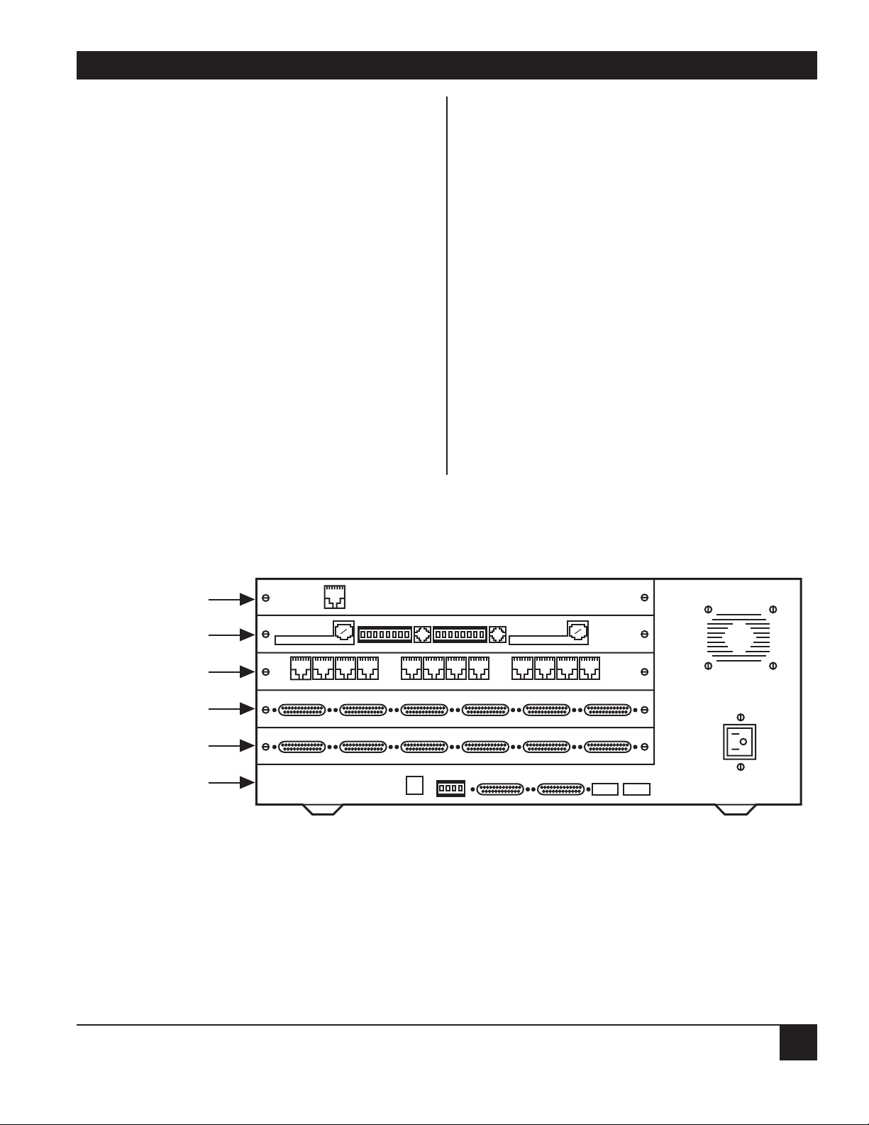
Figure 2-2. The back panel of a fully outfitted Multiserver 5000 is shown here. With the six-channel
sync/async expansion module in expansion slot B and the twelve-channel expansion module in
expansion slot C, this Multiserver 5000 could have up to 23 data channels. Ten of these data
channels could be synchronous. Expansion slot D has a two-channel voice/fax module,
allowing for all voice, fax, and data information to be sent over one leased line. The leased line
is connected to the Multiserver 5000 through the CSU/DSU module in expansion slot E.
12345678 12345678
S1 S2
1 2 4 5 6
ALARM
GCNO
NC
115/230
VAC
1 2 3 4 5 6 7 8 9 10 11 1212
A
B
C
D
E
31 2 4 5 6
DDS SERVICE
LINE 1
KTS
OPX
SB M E SG R1 T1 R T
VOICE CHANNEL 1
LOG PORT COMMAND
12345678 12345678
MODEM
ISU
VOICE/FAX
12-CHANNEL CEM
6-CHANNEL CEM
CCM
NMS
MODULE
KTS
OPX
SB M E SG R1 T1 R T
VOICE CHANNEL 2
3
Page 23

Multiserver 5000
22
PRODUCT NAME ............................................................ORDER CODE
MS1 56K CSU/DSU Module (cabling included) ................................MT150C
CSU/DSU MS ...................................................................................MT132A-R2
(External CSU/DSU to use with a Multiserver)
Male-to-Male Crossover Cable ...............................................EZ423-0015
MS RLB Module.....................................................................................MX229A
ThinNet Coaxial Cable................................................................LCN300A
PVC Transceiver Cable ...............................................................LCN200A
Thick Ethernet Tranceiver .............................................................LE003A
10BASE-T Transceiver ..................................................................LE2010A
10BASE-FL (Fiber) Transceiver................................................LE027A-ST
RISC Bridge/Ethernet (BNC connectors).......................................LB600A-R2
RISC Bridge/Ethernet 2 (AUI connectors) .....................................LB602A-R2
(External RS-232 Bridges to use with a Multiserver)
Straight-Thru Male-to-Female Cable .................................EDN25C-M/F
MS1 NMS Module .................................................................................MX227C
MS1 V.35 Converter/DCE (cabling included).......................................MX226
MS1 X.21 (V.11) Converter......................................................................MX228
X.21-to-DCE Cable ......................................................EVNX21-003M-MF
MS1 Rackmount Kit .................................................................................RM220
Communication Box II..........................................................................MX003A
(Requires one of the following CommPak cartridges)
Enhanced Statistical Multiplexor CommPak.............................MX100A
Quick Stat II CommPak ..........................................................MX107A-R2
Rackmount Kit for the CommBox II......................................................RM800
Voice Cards to use with the CommBox II:
Voice Card-1 (1-channel)..............................................................MX120C
Voice Card-2 (2-channel)..............................................................MX121C
(Note: Some older CommBoxes and CommPaks might
not be compatible. Current models are compatible.)
Statplex Multiplexor (4-port) ...............................................................MX611A
Statplex Multiplexor (8-port) ...............................................................MX622A
PRODUCT NAME ............................................................ORDER CODE
Multiserver 5000.....................................................................................MX219A
Straight-Thru Male-to-Male Cable (for DTE) .......................EZ422-0015
Straight-Thru Female-to-Female Cable (for DTE) ...............EZ425-0015
Straight-Thru Male-to-Female Cable (for DTE) ...............EDN16C-M/F
Male-to-Female Crossover Cable (for modem)....................EZ424-0015
Male-to-Male Crossover Cable (for modem)........................EZ423-0015
Multiserver 5000 CommPak (firmware for base unit)......................MX218C
Multiserver 1000.....................................................................................MX220A
Straight-Thru Male-to-Male Cable (for DTE) .......................EZ422-0015
Straight-Thru Female-to-Female Cable (for DTE) ...............EZ425-0015
Straight-Thru Male-to-Female Cable (for DTE) ...............EDN16C-M/F
Male-to-Female Crossover Cable (for modem)....................EZ424-0015
Male-to-Male Crossover Cable (for modem)........................EZ423-0015
Multiserver 1000 CommPak (firmware for base unit)................MX221C-R2
MS5 Expansion Module—Sync/Async (6-channel) ..........................MX215C
MS1 Expansion Module—Async Only (6-channel)..........................MX222C
Straight-Thru Male-to-Male Cable (for DTE) .......................EZ422-0015
Straight-Thru Female-to-Female Cable (for DTE) ...............EZ425-0015
Straight-Thru Male-to-Female Cable (for DTE) ...............EDN16C-M/F
Male-to-Female Crossover Cable (for modem)....................EZ424-0015
Male-to-Male Crossover Cable (for modem)........................EZ423-0015
MS1 Expansion Module—12 Async—RJ-45.......................................MX223C
DTE Adapter Male Kit (RJ-45 to DB25) (for DTE) .........................EZ419
DTE Adapter Female Kit (RJ-45 to DB25) (for DTE) .....................EZ421
DCE Modem Crossover Kit (RJ-45 to DB25) (for modem)...........EZ420
MS1 Expansion Module—12 Async—RJ-45 with Line Driver........MX224C
SHM-NPR connector (male) for DTE ....................................ME721A-M
SHM-NPR connector (female) for DTE...................................ME721A-F
RJ-45 Modular Cable (RJ-45 to RJ-45)..........................................EL08MS
MS1 Voice/Fax Card, 1 Channel (cabling included)......................MX225C-1
MS1 Voice/Fax Card, 2 Channels (cabling included)....................MX225C-2
Automatic Sharing Device-4 (ASD-4).....................................FX125A-R2
The Multiserver line of products, including compatible and supporting products
Page 24

CHAPTER 2: Introduction
23
2.3 The CommPak
The Multiserver 5000 Commpak plug-in software
cartridge contains all of the Multiserver 5000’s
operating software. To add features and program
upgrades is simple—just change the cartridge.
NOTE: The Multiserver 5000 CommPak cartridge is
required for the unit to operate.
2.4 Expansion Modules
Plug in up to three of these data expansion
modules to suit your data networking needs; use any
combination. Add the five data channels on the
CCM, and the Multiserver 5000 can support up to
41 data channels (ten of which may be
synchronous).
MX215C—6-channel sync/async data expansion
module with EIA RS-232C connectors.
MX222C—6-channel async-only data expansion
module with EIA RS-232C connectors.
MX223C—12-channel async data expansion module
with RJ1D connectors. These connectors are DB25compatible when used with the correct adapter
cables.
MX224C—12-channel async data expansion module
with RJ1D connectors and integral line drivers;
compatible with EIA RS-422 and RS-423 standards.
NOTE: The expansion modules can only go in slots
B, C, and D on the Multiserver.
2.5 MS1 Voice/Fax Card
The Multiserver 5000 can support up to eight
voice/fax channels with single- or dual-channel
voice/fax expansion modules. Once these modules
are installed, they can be fully configured from the
same command facility used to control the data
channels. The network manager has a single point
of control for the entire network.
NOTE: To get eight voice/fax channels, use four
dual-channel cards (MX225C-2). The cards
will occupy all of the rear-panel slots
available for expansion modules (except for
the NMS module, which fits underneath the
CCM).
The voice/fax modules support all telephone
interface types, including E&M Type 1–5 for PBX
operation, KTS for key telephone systems and
handsets, and OPX for off-premise exchange
operation. The module generates ring and dial-tone
when required. There is no need to install external
signal converters.
These modules integrate voice, fax and data signals,
automatically switching the integrated software for
fax demodulation when it detects a fax signal and
resuming speech (voice) compression when it
identifies a voice signal.
2.6 MS1 56K CSU/DSU Module (MT150C)
Use the integral CSU/DSU module to interface the
Multiserver 5000 to a 56-Kbps digital line. The
Automatic Line Buildout (ALBO) feature makes
installation very simple: the CSU/DSU can
automatically adjust signal output according to line
distance (that is, the distance between the
CSU/DSU and the first repeater in the DDS line to
which it is attached). You won’t have to worry about
cable-length equalization problems during
installation.
2.7 MS RLB Module (MX229A)
The MS RLB Module is a Remote Ethernet LAN
Bridge. Once the RLB is installed, LAN bridge
traffic is integrated with voice and data traffic over
your leased line.
The RLB is a standard MAC-layer bridge and is
compatible with any ethernet protocol. The RLB
supports 802.1D Spanning Tree protocol to prevent
network loops. Bridge management can be done
through the Multiserver’s Command Facility.
Page 25

Multiserver 5000
24
2.8 MS1 NMS Module (MX227C)
The MS1 NMS Module (network management
system module) fits underneath the CCM on the
rear panel of the Multiserver 5000. It features a
command port to hook up a PC or terminal, a
printer log port to connect a serial printer, and an
alarm relay. You can run diagnostic tests and
generate statistics reports, and then print the results
(logs) on your own connected printer.
2.9 MS1 V.35 Converter/DCE (MX226)
The MS1 V.35 Converter/DCE plugs into an
interconnect- or mux-link port on the CCM
(locations A1 to A5). Then you can interface the
port with a DCE that operates according to the V.35
recommendation.
NOTE: Use of this converter module requires a
separate DCE interface cable, which is
included.
2.10 MS1 X.21 (V.11) Converter (MX228)
The MS1 X.21 (V.11) Converter plugs into a muxlink port on the CCM (locations A1 to A5). Then
you can interface the port with a DCE that operates
according to the X.21 (V.11) recommendation.
NOTE: Use of this converter module requires a
separate DTE or DCE interface cable. Order
cable number EVNX21-003M-MF.
2.11 MS1 Rackmount Kit (RM220)
The RM220 rackmount kit lets you mount the
Multiserver 5000 in your present 19-inch rack
system.
2.12 Documentation
There is a Menu Flow Diagram and a Multiserver 5000
LCD/Keyboard Menu Flow Chart inside the back cover
of this manual. If the Menu Flow Diagram or the
Multiserver 5000 LCD/Keyboard Menu Flow Chart is
missing, please contact your dealer to receive a
copy. Use these diagrams to quickly find a system
menu and to learn how the menus are grouped and
linked.
You should also have User’s Manuals for the
following optional modules or kits you may have
ordered with the Multiserver 5000:
MS1 Voice/Fax Card User’s Manual — A detailed
description of the 1- and 2-channel voice modules,
including fax operation.
MS1 56K CSU/DSU Module User’s Manual — A
detailed description of 56K CSU/DSU module,
including a number of diagnostic tests.
MS RLB Module User’s Manual — A detailed
description of the MS RLB (Remote LAN Bridge)
module.
MS1 NMS Module User’s Manual — A detailed
description of the Network Management System
module.
Page 26

CHAPTER 2: Introduction
25
2.12 Manual Text Conventions
This manual uses the following standard
conventions:
Partial menus are shown, and they
will be in the following format:
Menu flows will show you what
option you should select. The
option is usually shown in a box:
Text in bold represents the response
you should enter to a prompt:
In this example, a Y was entered.
<cr> or cr Press the RETURN key on your
keyboard
<break> Press the BREAK key on your
keyboard
<esc> Press the ESCAPE key on your
keyboard
^ CONTROL key on the keyboard.
Indicates that the Control key is to
be held down while you press the key
that follows this symbol. For
example, ^X means “press the
control key and hold it down while
you press X.”
Press displayed key(s) on your
keyboard, then press <cr>.
courier Text in courier is what the
Multiserver displays or what you
enter into your terminal’s keyboard.
bold Text in bold refers to other chapters,
sections, appendixes, figures, or
tables within this manual.
italics Text in italics refers to other manuals
or documentation.
[brackets] Text in brackets refers to the current
value of a variable. For example, the
Command Facility Main Menu
displays [node id]. The default
value for a node ID is !240. If the
node ID is still set for the default
value, the Multiserver would display
COMMAND FACILITY MAIN MENU
[!240].
M - This will appear at the bottom of
MAIN MENU some menus. When you press
M, the
Command Facility Main Menu
appears.
COMMAND FACILITY MAIN MENU [node id]
1. VIEW CONFIGURATION
2. STATUS/STATISTICS
3. CONFIGURE LOCAL NODES
CONFIGURE LOCAL NODES
3
3
ENTER A “Y” TO CONFIRM OR
“N” TO ABORT: Y
Page 27

Multiserver 5000
26
Page 28

Multiserver 5000
26
3.1 Initial Considerations
The Multiserver 5000 offers the ability to connect
one of the following units and their associated links:
• Multiserver (1000 or 5000) via an Interconnect
Link.
• Feeder Mux (Communication Box II or Statplex
Multiplexor) via a Mux Link or an X.21 Link
The interconnect link can be connected using the
integral MS1 56K CSU/DSU module. Any of the
links can be connected using an external ISU or
modem. If the external devices are not
RS-232, the appropriate converters are required.
The Multiserver 5000 supports four types of
network topologies:
• Point-to-point
• String
• Star
• Distributed Star
Utilizing these topologies, the Multiserver 5000 can
serve as either a terminated node (traffic is
terminated in, or attached to the local node) or a
switching hub (no local attached devices). Without
local traffic (data/voice/LAN), the Multiserver’s
link capacity increases.
There are three elements to be considered when
putting together a Multiserver 5000 network:
• Channel Performance
Burst 288 Kbps
• Link Capacity
Terminated 72 Kbps
Switched 192 Kbps
• Delay (varies Do not exceed six link
between channel hops in any network
type and protocol) path (6 node hops)
Important
You cannot have a closed loop in a
Multiserver network.
When designing a Multiserver network, it helps to
keep in mind the different capabilities of the
Multiserver 1000 and Multiserver 5000. A summary
of these are detailed in Table 3-1.
3. Network Design and Topologies
Table 3-1. Comparison of the Multiserver 1000 and the Multiserver 5000
Multiserver 1000 Multiserver 5000
Number of possible interconnect links 1 (A1) 3 (A1 to A3)
Speed: interconnect link 1.2 to 64 Kbps 1.2 to 72 Kbps
Number of possible feeder-mux links 1 (A1) 5 (A1 to A5)
Speed: feeder-mux link Up to 19.2 Kbps Up to 19.2 Kbps
Max. number of data channels 41 41
Max. number of sync data channels 1 10
Sync protocol speeds (most applications) 1.2 to 19.2 Kbps 1.2 to 38.4 Kbps
Max. number of voice/fax channels 4 8
Dual-link load balancing capability no yes
Multi-point capability no yes
Page 29

CHAPTER 3: Network Design and Topologies
27
3.4 Syntax for Node Numbers and IDs
Multiserver units and compatible multiplexors
share the same syntax for the node numbers and
IDs.
Node # Syntax: Use 1 through 254. (Number 1 is
input as 1, not 001.)
Node ID Syntax: One to eight uppercase or
lowercase characters. Any combination of
alphanumeric characters and underscore ( _ ) is
allowed. No spaces are permitted. Node IDs are not
case-sensitive. They should be as short as possible.
Using the syntax described and a sample worksheet
copied from Appendix A, plan the node numbers
and node IDs that will be used in your network.
Make sure that you plan the port and channel
assignments, etc., for your network before reading
the rest of this manual. Worksheets for the channels
are also in Appendix A.
3.5 Default Node Numbers and Node IDs
The units are shipped with default configurations.
These default settings are listed in Table 3-2. (See
Appendix C for a complete listing of all Multiserver
5000 default settings.)
Figures 3-1, 3-2, and 3-3 are typical Multiserver
networks and give the default settings of each node.
If the optional NMS module is installed, the default
3.2 Worksheets for the Network
Appendix A contains worksheets you can use to
plan your network. Make photocopies of the
worksheets you will need and then complete them.
You will need to refer back to your worksheets for
other aspects of the configuration process later in
this manual.
3.3 Nodes and Hubs
Each Multiserver and compatible multiplexor in a
network is referred to as a node. Each node must
have its own node number and node ID. These are
used by the Multiserver system to identify each node
in the network.
NOTE: There must be no duplicate nodes in the
network!
All nodes connected locally are considered a local
hub group. This includes the Multiserver 5000 and
any feeder muxes connected directly to it.
All nodes on the other side of an interconnect link
are considered a remote hub group. There may be
feeder muxes connected directly to the remote
Multiserver. They are considered part of the remote
hub group.
Table 3-2. Multiserver and Feeder Mux Default Node Numbers and IDs
Default Node Default Node
Unit Number ID
Multiservers: 1000 240 !240
5000 240 !240
Feeder Muxes: Mux Connected to Port
A1 241 !241
A2 242 !242
A3 243 !243
A4 244 !244
A5 245 !245
Page 30
Multiserver 5000
28
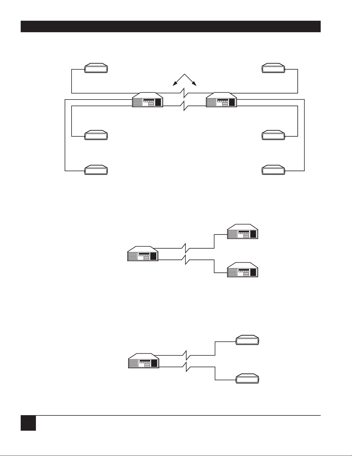
Figure 3-1. In this distributed star, A1 and A2 are interconnect links. A3, A4, and A5 are mux links.
Figure 3-2. A1 and A2 are interconnect links.
Figure 3-3. A1 and A2 are mux links.
Multiserver 5000
Multiserver 5000
Multiserver 5000
Multiserver 5000
Multiserver 5000
Multiserver 5000
CommBox II
CommBox II
CommBox II
CommBox II
CommBox II
CommBox II
CommBox II
CommBox II
Local Hub Group Remote Hub Group
PORT
A3
A4
A5
A1
A2
A1
A2
A3
A4
A5
A1
A2
A1
A2
Page 31

CHAPTER 3: Network Design and Topologies
29
3.6 Examples of Network Designs
SINGLE LINK POINT-TO-POINT
The most basic of topologies is the point-to-point: point A to point B. A point-to-point switching topology is
shown in Figure 3-4. Multiserver 5000 units can operate in a point-to-point switching topology over
terrestrial, satellite, and microwave services at speeds ranging from 9.6 to 72 Kbps. Feeder muxes can be
attached to either or both ends of the network.
Figure 3-4. Point-to-Point Switching Topology.
PC
PBX
PHONE
ASCII TERMINAL
FAX MACHINE
PBX
NODE BNODE A
MULTISERVER
5000
MULTISERVER
5000
LINK A
FAX MACHINE
HOST
Page 32

Multiserver 5000
30
DUAL LINK POINT-TO-POINT
Figure 3-5 illustrates a dual-link, point-to-point application. All traffic between Multiserver nodes is loadbalanced between Link A and Link B. In the event of a single link failure, all traffic is automatically rerouted
over the secondary link (link B).
In a single-link, point-to-point application, the interconnect link can be configured from 9.6 to 72 Kbps.
When load-balancing, each link must necessarily be slower that in a single-link application. So even though
the aggregate link speed available might equal or exceed the single-link application, the slower links may limit
the number or certain types of devices that can operate on the network. This will depend upon your
particular application.
Figure 3-5. Typical Point-to-Point, Dual Link with Load Balancing.
PC
PBX
ASCII TERMINAL
FAX MACHINE
PBX
MULTISERVER
5000
LINK A
LINK B
NODE BNODE A
MULTISERVER
5000
FAX MACHINE
HOST
Page 33

CHAPTER 3: Network Design and Topologies
31
STRING
If several Multiserver units are strung together, a string topology is created (Figure 3-6). The limitations to
this application are the following:
• Maximum six hops
• No closed loops
Any or all of these may be Multiserver 5000 units. Three Multiserver units in a string can also be considered
a “V” or drop-and-insert application (see Figures 3-7 and 3-8).
Figure 3-6. Typical String Network.
Figure 3-7. Simple “V”. Figure 3-8. Drop and Insert.
first hop
second hop
third hop
fourth hop
Multiserver 5000
Multiserver 5000
Multiserver 5000
Multiserver 5000 Multiserver 5000
Multiserver 5000
Multiserver 5000
Multiserver 5000
Multiserver 5000
Multiserver 5000
MULTISERVER
5000
PBX
V APPLICATION
DROP AND INSERT
APPLICATION
HOST
MULTISERVER
5000
HOST
MULTISERVER
5000
Page 34

Multiserver 5000
32
STAR
The star topology (Figure 3-9) is a network with a single major center (hub) connected to (up to) five access
points. The Multiserver 5000 can have three of the links connected to other Multiserver units with two
additional links connected to feeder muxes.
Figure 3-9. Typical Star Application.
Command
Terminal
NETman
FAX
HOST
PBX
MULTISERVER
5000
MULTISERVER
5000
MULTISERVER
1000
MULTISERVER
1000
Page 35

CHAPTER 3: Network Design and Topologies
33
DISTRIBUTED STAR
If two Multiserver star networks are connected, the topology can be described as a distributed star.
Figure 3-10 shows two star networks connected to form a distributed star.
Figure 3-10. Typical Distributed-Star Application.
FEEDER MUX
MULTISERVER
1000
MULTISERVER
1000
FEEDER MUX
MULTISERVER
5000
FEEDER MUX
MULTISERVER
1000
MULTISERVER
1000
FEEDER MUX
Page 36

Multiserver 5000
34
This chapter explains how to install the Multiserver
base unit. Once installation is completed, you will
be ready to configure. It is assumed that your
Multiserver has all optional modules already
installed. Module installation is discussed in chapter
5. You should not hook up the interconnect link or
the system can generate an error message.
4.1 Check Contents
Check the packing list against the contents of the
box. Report any damage to the shipping carrier.
Keep the packing materials; you may need them to
repack the unit for factory update or repair.
4.2 Plan the Location Based on the Physical
Description and Requirements
Unit Weight: 22 lb. (10 kg)
Temperatures: Surrounding temperatures during
operation should not exceed the following
extremes: 32 to 122°F (0 to 50°C) with 10 to 90%
relative humidity (noncondensing)
Distance to AC Power Socket: Should not exceed
six feet (1.8 meters). Do not use extension cords
that may inhibit your unplugging the system in
event of an emergency.
Power: 90-265 VAC (no strapping required), 3/1.5
amps, 47-63 Hz, 135 watts maximum
General Cabling Requirements: Most cables must
be shielded to comply with the requirements of the
following government agencies:
U.S.A. - Title 47 of the Codes of Federal
Regulations, FCC Rules and Regulations,
Part 15
Canada - DOC SOR 88/475
Germany - FTZ Reg. No. 1046
To avoid interference, do not run cables parallel to
AC wiring, or near fluorescent lights or other
magnetic fields.
External Converter Requirements: Shielded cables
are required, except for the V.35 converter.
4. Base-Unit Installation
Figure 4-1. Physical Dimensions of the Multiserver base unit.
You should leave space behind the unit for cabling and converters.
UP TO 12 INCHES (30.5 CM)
12 INCHES
(30.5 CM)
MULTISERVER 5000
17.5 INCHES
(44.5 CM)
EXE
6.5 INCHES
(16.5 CM)
Page 37

CHAPTER 4: Base-Unit Installation
35
4.2 CommPak Cartridge Installation and
Removal
INSTALLING THE COMMPAK CARTRIDGE
The CommPak cartridge contains the operating
software for the Multiserver. When a cartridge is not
being used, it should be stored in an anti-static bag.
It is assumed that the CCM is installed. You cannot
install the CommPak cartridge unless the CCM is
installed.
Warning!
Any time that a CommPak is installed
or removed from the base unit, be sure
that the power cord is unplugged.
Failure to do so could result in damage
to the CommPak cartridge.
R
EMOVING THE COMMPAK CARTRIDGE
If you ever need to remove the CommPak cartridge
(such as for upgrading purposes), these are the
steps you should follow:
1. Unplug the power card from the ac power
socket.
2. Pull out the right side of the extractor handle.
3. Slide out the cartridge. The door will close
behind it.
4.3 Power Up the Unit
After the CommPak cartridge is installed in the
unit, plug the power cord into the back of the unit
and into the wall outlet. The Multiserver will power
up and automatically go into a self-test mode
(which lasts approximately 30 seconds).
4.4 LCD Display
Figure 4-2. Step one: Slide the CommPak
cartridge into the bottom beveled door.
The door will move out of the way.
(Do not use the top slot.)
Figure 4-3. Step two: Be sure to push in the
cartridge until it is flush against the
unit. To fully seat the CommPak
cartridge, you will need to exert
pressure. There must be no gap
between the cartridge and the unit.
Figure 4-4. Pull out the extractor handle in order
to remove the CommPak cartridge.
Figure 4-5. Plug in the power cord after the
CommPak is installed.
EXE
MULTISERVER 5000
EXE
MULTISERVER 5000
EXE
MULTISERVER 5000
Page 38

Multiserver 5000
36
On the front of the unit is a liquid-crystal display
(LCD). After the unit completes its internal tests,
the clock will start and the LCD will display a
message.
The LCD backlight will also flash. This indicates
that there is alarm message, probably Local Link
reset A1. This means that the default link
channel has been reset. The backlight will
eventually time out. See Section 13.1, General
LCD/Keypad Information if you wish to stop the
backlight from blinking before it times out.
4.5 Checking the CCM Indicators
Once the self-test has been completed, the CCM
indicators on the front of the unit should display AT
on and BO off. The indicators for port A1 will be
flashing, unless it is correctly attached to an
interconnect link. The indicators for ports A2 to A6
will probably be off, though any or all may flash.
This will depend on how each of the ports is
configured. Figure 4-7 shows the most-probable
status of your indicator lights when you power-up
the Multiserver for the first time.
If the CCM indicators are lit differently:
• Refer to Table 4-1 on the next page for indicator
interpretation,
• Check that the CommPak cartridge is fully
seated, and
• Make sure that the wall outlet is operational.
Multiserver 5000 Time: 00:01:23
Figure 4-6. Default LCD message after power-up.
Figure 4-7. CCM indicators at the time of power-up.
LCD DISPLAY
CCM indicators
Normal Status
On Power Up
AT BO A6 A5 A4 A3 A2 A1
Key:
LED on
LED off
LED blinking
A1-A6 = port numbers
BO = buffer overflow
AT = active mode
Page 39

CHAPTER 4: Base-Unit Installation
37
4.6 Identify the Module Locations and
Channel Numbers
MODULE LOCATION AND NOMENCLATURE
There are five chassis positions available for
modules in the Multiserver 5000. These are
identified from bottom to top as module locations
A through E.
• The Communications Control Module (CCM) is
always in module location A.
• A space is reserved below the CCM for the
optional NMS module. Its module location
is “$.” Note that there is no “$” printed on the
rear-panel of the Multiserver 5000.
• Optional modules can fill module locations B
through E.
C
HANNEL LOCATION AND NOMENCLATURE
Channel numbers are assigned to all the ports on
Table 4-1. CCM Indicator LEDs
INDICATOR STATUS EQUIPMENT STATUS
AT BO A6 A5 A4 A3 A2 A1
10 XXXX XX1Normal equipment status
0 0 1 0 0 0 0 0 ROM Test Failure (CommPak cartridge
failure)
0 0 0 0 0 0 0 1 CMOS Failure
2
0 0 0 0 0 0 1 0 Battery low
3
0 1 1 0 0 0 0 0 RAM Failure in CommPak cartridge
1 0 1 0 1 0 1 0 Parity error
1 1 1 1 1 1 1 1 CommPak cartridge not installed
properly or defective Multiserver unit
0 1 0 0 0 0 0 0 RAM Test Failure (CCM)
KEY
0 = LED off
1 = LED on
X = LED can be off or on. This will change as the status of the port activity changes.
1
If A1 is configured as a link, it blinks on power-up with no established link. (The default setting is for A1 to be
configured as a link.)
2
System can still operate with CMOS failure. All configuration data has been lost in the affected CMOS section,
and default values have been supplied.
3
System can still operate with a low battery. Configuration data may be lost if the Multiserver loses power.
Page 40

Multiserver 5000
38
the Multiserver 5000.
• The CCM module has six connectors and is
located in module location A. From left to right
these connectors are numbered sequentially (1
to 6).
The channel numbers correspond to the
module and connector locations. The channel
number for the connector on the far left side is
A1. The next connector to the right is A2, and
so on to the last connector, A6.
• The NMS Module has two channel numbers:
The Log Port is $1 and the Command Port
is $2.
• In the example shown in Figure 4-8, the
Channel Expansion Module (CEM) in location
B has 12 connectors, and their channel numbers
are B1 through B12.
• In the same example, the voice module in
location C has two voice channels, C1 and C2.
Figure 4-8. Module and Channel Nomenclature.
CHANNEL NUMBER B12
CHANNEL NUMBER $2
MODULE
MODULE
LOCATIONS
LOCATIONS
E
D
C
B
A
CHANNEL NUMBER A1
LOCATION OF CONNECTOR
NUMBER 1
Page 41

CHAPTER 4: Base-Unit Installation
39
Figure 4-9. The CCM Board. The front-panel of the unit is to the left.
Jumper E1
J16
E1
J14
J15
BATTERY
J13
J11
PORT 6
PORT 5
PORT 4
J17 J18
J1 J2 J3 J4
PORT 3
PORT 2
PORT 1
Page 42

Multiserver 5000
40
5.1 Module Stacking Order
Although you are not actually installing the
modules yet, it is important to become familiar with
the five chassis positions available for modules in
the Multiserver unit. These are identified from
bottom to top as module locations A through E (see
Figure 5-1). The possible hardware-configuration
combinations are numerous. Regardless of the
combination you choose, the Communications
Control Module (CCM) must always be in module
location A. The optional NMS module is always
installed directly below the CCM. The rest of the
modules should be installed in the following order,
from bottom to top:
• 6-channel CEM
• 12-channel CEM
• Voice/fax module
• RLB module
• 56K CSU/DSU module
Stacking is done from bottom to top without
skipping a module location. For example, if you
have three modules (a CCM and two optional
modules), the modules should be stacked in
module locations A through C with locations D
and E left open. If there are four modules, module
location E will be left unused.
5. Module Installation
Figure 5-1. A letter on the right side of the module indicates location.
LETTERS THAT INDICATE
MODULE LOCATION
MODULE
ISU
VOICE/FAX
12-CHANNEL CEM
6-CHANNEL CEM
CCM
NMS
DDS SERVICE
LINE 1
VOICE CHANNEL 1
SB M E SG R1 T1 R T
1 2 4 5 6
KTS
OPX
1 2 3 4 5 6 7 8 9 10 11 1212
31 2 4 5 6
3
ALARM
GCNO
MODEM
NC
VOICE CHANNEL 2
SB M E SG R1 T1 R T
LOG PORT COMMAND
KTS
OPX
S1 S2
12345678 12345678
12345678 12345678
E
D
C
B
A
115/230
VAC
Page 43

CHAPTER 5: Module Installation
41
5.2 Module-Location Switch Settings
Each expansion module has a module-location
switch group S1 that informs the software of its
location in the Multiserver unit (see Figure 5-2).
There are two exceptions: the CCM, which is always
in module location A, and the NMS module, which
is always located below the CCM. The physical
location of the switch is unique to each module.
Switch group S1 consists of four positions
numbered 1 through 4. Before setting S1, first
determine the location where the module is to be
installed. Then, set the switches to match the
intended module location. For example, if the
intended module location is C, set switch 2 on,
and the other three off. To set a switch on, use
a ballpoint pen or similar pointed tool and push
the switch down.
NOTE: Switch group S1 settings for module
locations B through E are different for each
module location (see Figure 5-2). Be sure
that each switch reflects the correct setting
for the intended module location. Also, take
care that only one switch is on (down) and
that the remaining three switches are off
(up).
Figure 5-2. Switch S1 and module location settings.
Up position = open = off
Down position = closed = on
SWITCH
1
2
3
4
GROUP
S1
OPEN
FOR MODULE
LOCATION B
OPEN
FOR MODULE
LOCATION C
OPEN
FOR MODULE
LOCATION D
OPEN
FOR MODULE
LOCATION E
Page 44

Multiserver 5000
42
5.3 Inter-Module Stacking Connectors
The modules are powered via the stacking
connector located on the front right side looking
from the front of the Multiserver unit. In Figure 5-3,
the back of the unit is shown, and the connectors
are therefore on the left. A stacking connector has
two parts: a shroud and a block. The shroud is on
the bottom of the module being installed and fits
over the block on the module below. As you
position the module, align the shroud and the
block. Press the two together until the connector is
completely coupled. Make sure that the holes in the
front of the module are aligned with the pins on
the spacer.
Figure 5-3. Inter-module stacking connectors.
BACK
FRONT
STACKING
CONNECTOR
(BLOCKS)
SHROUD
BLOCK
Page 45

CHAPTER 5: Module Installation
43
5.4 Blank Back Panel
The unit is delivered with blank back panels to
eliminate an open area in the rear of the unit where
there are no modules installed (Figure 5-4). Do not
discard unused blank back panels; they may be
needed later.
5.5 Disassembly Procedures
The disassembly of your Multiserver unit will
require access to the sides and top of the unit to
remove the cover, and to the rear to remove the
back panels. This may be accomplished with the
unit in its normal operating position provided there
is sufficient clearance—about six inches above the
unit and the length of a screwdriver on either side.
If there is not a sufficient amount of access space,
you will need to remove all external cables to move
the unit to a work space.
Figure 5-4. The back of a multiserver unit with a blank panel.
Figure 5-5. Unplug the Multiserver before disassembly.
BLANK PANEL
Page 46

Multiserver 5000
44
5.5.1 UNPLUG THE MULTISERVER
Remove the power cord from the wall outlet.
The Multiserver unit contains electrosensitive
components that could suffer damage from static
discharge. Ground yourself by touching any
grounded equipment. Touching the Multiserver’s
chassis will not work. Since the unit is now
unplugged, it is no longer grounded.
5.5.2 R
EMOVE THE COVER
Using a Number 1 or Number 2 Phillips
screwdriver, unscrew the four screws (two on each
side) that secure the cover (Figure 5-6).
Lift off the cover.
Your cover has metallic finger stocks (Figure 5-7).
Be careful not to handle them when removing the
Figure 5-6. Remove the cover after taking out four fastening screws.
Figure 5-7. Avoid handling the fine metal teeth on the edge of the cover.
AT BO A6 A5 A4 A3 A2 A1
DO NOT
TOUCH
Page 47

CHAPTER 5: Module Installation
45
cover. The delicate metallic finger stocks are located
at the front and rear of the cover. They are needed
to make contact with the bottom enclosure and to
ensure compliance with FCC Part 15 or FTZ
radiated emission standards.
5.5.3 REMOVE BLANK BACK PANELS
Each blank back panel is supported by two retaining
screws. To remove the panel, unscrew and remove
the screws. Then pull off the panel.
Remove all blank back panels down to the top
module board.
Figure 5-8. Remove any blank panels.
Figure 5-9. Remove spacers.
NUMBER 1
SPACER
Page 48

Multiserver 5000
46
5.5.4 REMOVE SPACERS
Inside the front of the Multiserver unit, there are
six spacers for positioning the modules (see
Figure 5-9). To remove a spacer, simply slide the
spacer up and out of the unit. Set the spacers aside
for reassembly. The bottom-most spacer (the
number 1 spacer in Figure 5-9) should remain in
the unit.
5.5.5 D
ISASSEMBLY CONSIDERATIONS
Adding a CSU/DSU Module. The disassembly
procedures end here. Refer to MS1 56K CSU/DSU
Module User’s Manual for installation guidelines.
Adding an RLB (Remote LAN Bridge) Module. Remove
the CSU/DSU module (if appropriate). Refer to
MS RLB Module User’s Manual for installation
guidelines.
Adding a Voice/Fax Module. Remove the CSU/DSU
module and/or the RLB Module (if appropriate).
Refer to MS1 Voice/Fax Card User’s Manual for
installation guidelines.
Adding a Channel Expansion Module (CEM). Remove
Voice/Fax card(s), RLB Module, and/or CSU/DSU
module (if appropriate). See Section 5.7.1 for
installation guidelines.
Adding an NMS Module. The addition of the NMS
module will require the removal of all the modules,
including the CCM. Follow the CCM Removal
instructions (Section 5.5.7). Refer to the MS1 NMS
Module User’s Manual for installation guidelines.
5.5.6 R
EMOVING A CHANNEL EXPANSION MODULE
(CEM), VOICE/FAX CARD, OR CSU/DSU MODULE
1. Disconnect any external cables connected to the
module.
2. Unscrew the two screws in the back panel.
3. Gently remove the board by lifting it up and
making sure that the stacking connectors
disengage.
4. Remove the spacer associated with the module if
you need to remove the next module.
5.5.7 REMOVING THE CCM
1. Before removing the CCM, remove the
CommPak cartridge and place it in an antistatic
bag. (See Section 4.2, CommPak Cartridge
Installation and Removal.)
2. Disconnect all external cables \connected to the
CCM. Remove any converters, if installed.
3. Disconnect the 12-pin power supply harness from
the CCM (see Figure 5-10).
4. Disconnect the 26-pin LCD ribbon cable from
the CCM.
Figure 5-10. Disassembling the CCM.
12-PIN POWER
CONNECTOR
26-PIN RIBBON
CONNECTOR FROM LCD
FAN CONNECTOR
34-PIN RIBBON CONNECTOR
FROM NMS MODULE
Page 49

CHAPTER 5: Module Installation
47
5. Disconnect the fan connector from the CCM.
6. Disconnect the 34-pin NMS module ribbon cable,
if it is installed.
7. Unscrew the two screws in the back panel.
8. Gently remove the board by lifting it up.
5.6 Installation Procedures
The Multiserver unit contains electrosensitive
components that could suffer damage from static
discharge. Ground yourself by touching any
grounded equipment. You cannot ground yourself
by touching the Multiserver’s chassis. When the unit
is unplugged (off), it is not grounded.
External cables should not be connected until all of
the module installation is complete.
5.6.1 I
NSTALL THE SPACERS
Spacers must be inserted in the unit before
replacing the cover. Install a spacer in between each
of the modules. The spacers serve to maintain a
firm connection for the module connectors and to
secure the front of the modules.
5.6.2 I
NSTALL THE CCM
The CCM is always installed in module location A.
No other placement is permitted.
1. If the optional NMS Module has been purchased,
install it before installing the CCM. Refer to the
MS1 NMS Module User’s Manual for installation
guidelines.
2. Place the CCM module on the spacer in the front
of the unit.
3. Align the two holes on the module back with the
two holes on the back of the chassis. Using screws,
join the back panel to the chassis.
4. Connect the 12-pin power supply harness to the
CCM.
Figure 5-11. Installing the CCM.
26-PIN RIBBON
CONNECTOR FROM LCD
12-PIN POWER
CONNECTOR
FAN CONNECTOR
34-PIN RIBBON CONNECTOR
FROM NMS MODULE
Page 50

Multiserver 5000
48
5. Connect the 26-pin LCD ribbon cable to the
CCM.
6. Connect the fan connector to the CCM.
7. Connect the 34-pin NMS Module ribbon cable, if
installed, to the CCM.
8. Place a spacer on top of the CCM by inserting it
at the top of the bezel at the front of the unit and
then sliding it down until it rests on the module .
5.6.3 I
NSTALL CHANNEL EXPANSION MODULES
These instructions cover both 6- and 12-channel
CEMs.
Channel Expansion Modules (CEMs) may be
installed in chassis positions B, C, and D.
Installation in position E is not allowed.
1. Make sure that a spacer is in between the
previous module and the module to be installed.
2. Set switch group S1 according to the module
location switch setting (see Section 5.2, Module
Location Switch Settings).
3. If the module is a 12-Channel Line Driver
Expansion Module, then verify that the jumper on
header E1 is placed in the proper position for
RS-422 or RS-423 operation for ports 1 to 6, and
that the jumper on header E2 is in the proper
position for ports 7 to 12 (Figure 5-12).
NOTE: A 12-channel expansion module with line
driver can be configured for 422 or 423
operation, but not for both. Both E1 and E2
must be configured identically.
4. Place the module on the spacer in front.
5. Connect the inter-module stacking connectors.
6. Align the two holes on the module back with the
two holes on the back of the chassis. Screw the back
panel to the chassis.
Figure 5-12. The 12-channel Channel Expansion Module with Line Drivers.
RS-423
E2
PORTS 7-12
E1
PORTS 1-6
S1
RS-422
Page 51

CHAPTER 5: Module Installation
49
5.6.4 REMAINING SPACERS
When finished installing the modules, reinstall any
remaining spacers.
5.6.5 INSTALLING BLANK BACK PANELS
The space above the last module installed must be
filled with blank back panels for the following
reasons:
• To provide a safe unit
• To ensure proper air flow over the modules
• To keep excessive dirt or contamination out of
the unit
•
To be in compliance with radiated emission
standards such as FCC Part 15 and FTZ.
To install, first locate the top side of the panel. The
top side is identified by the dimples on the surface
of the panel (Figure 5-14). Place the blank panel on
the outside of the unit, aligning the two screw holes.
The action of screwing in the screws will bring the
holes into perfect alignment and will cause the
blank back panel to fit snugly against the back panel
beneath it. The screws should be snug but not so
tight as to strip the threads.
Figure 5-13. Reinstalling spacers.
Figure 5-14. Installing a blank panel.
BLANK BACK PANEL
DIMPLES ON TOP OF BACK PANEL
Page 52

Multiserver 5000
50
5.6.6 PUT THE COVER BACK ON
1. Be sure that all spacer positions have been filled
before replacing the cover to ensure proper
module connections.
2. Be sure blank back panels have been installed
into the back of the unit to eliminate open
spaces.
3. Be careful not to handle the delicate metallic
finger stocks when installing the cover. They are
located at the front and rear of the cover and
are needed to make contact with the bottom
enclosure to ensure compliance with FCC Part
15 or FTZ radiated emission standards.
4. The front of the cover has an interrupted strip
of metallic finger stocks. The back has a solid
strip. (See Figure 3-15.)
Identify the front of the cover, align it with the
front of the base, and place the cover over the
base. Lightly press the cover forward.
5. Insert screws in holes and screw them in with a
screwdriver. The screws should be tightened
until they stop turning under normal pressure.
Figure 5-16. Putting the cover back on the Multiserver.
Front
Back
Figure 5-15. The front and back of the cover.
AT BO A6 A5 A4 A3 A2 A1
Page 53

CHAPTER 5: Module Installation
51
5.7 Converters (Optional Equipment)
The converter is attached externally to the
Multiserver unit. The V.35 and X.21 Converters
consist of an adapter (which connects directly to
the Mulitserver) and a cable. The cable is included
with the V.35 converter. The cable is not included
with the X.21 converter. See
Appendix B for cabling diagrams.
I
NSTALLING CONVERTERS
A converter may be installed at any time after the
internal modules are installed (see Figure 5-17).
Unplug the Multiserver to install a converter. The
external unit that will be connected to the
Mulitserver via the converter should also be
unplugged.
1. Attach the converter to the desired port by
matching the DB25 connector.
2. Screw in the two side screws which hold the
converter in place.
3. Connect the cable to the converter.
R
EMOVING CONVERTERS
A converter can be removed without opening the
cover or removing any of the modules.
1. Remove all cables connected to the converter.
2. Unscrew the two side screws that hold the
converter in place.
3. Gently separate the connector from the
Multiserver port.
Figure 5-17. Converter installation (showing a V.35 converter and cable).
5-foot DB25 (male) to 34-pin M-block (male)
(Cable is included with the V.35 Converter)
KTS
DB25
(RS-232)
DCE
VOICE CHANNEL 1
SB M E SG R1 T1 R T
12 456
OPX
1 2 3 4 5 6 7 8 9 10 11 1212
3
VOICE CHANNEL 2
SB M E SG R1 T1 R T
E
D
KTS
OPX
C
B
A
CONVERTER
Page 54

Multiserver 5000
52
6.1 Multiserver Base Unit Location
Your Multiserver should be installed at its location.
If you have a Rackmount Kit, install it now (see
Appendix G). Place the Multiserver in the
Rackmount Tray when completed.
6.2 Connecting an ASCII Terminal
You will need to connect an ASCII terminal to the
Multiserver in order to access the Command Mode
and the Command Facility. The Command Mode
offers complete configuration and administration
options. The fold-out Menu Flow Diagram inside
the back cover of this manual provides an overview
of the menus available in the Command Mode.
If you have an optional NMS module installed,
connect an ASCII terminal to the NMS Command
Port.
If you do not have the NMS module, connect an
ASCII terminal to any asynchronous port in the
unit. Channels A2 through A6 on the CCM are by
default asynchronous channels. In Figure 6-1, the
ASCII terminal has been connected to channel A5.
A user-supplied straight cable must be used to
connect the ASCII terminal to the unit. (Pin
assignments are shown in Appendix B.)
The ASCII terminal you connect must initially have
the characteristics listed in Table 6-1. If necessary,
refer to the terminal’s manual for information on
how to reset these parameters.
All parameters except the operation parameter can
be reconfigured. The operation parameter cannot
be changed and must remain in full-duplex.
If you need to reconfigure the port settings, refer to
Section 11.2, Command Mode.
Attention
For ports configured as interconnect
links, do not connect their cables at
this time. If you do, the system will
display a DUPLICATE NODE-ID error
message. To avoid this error, connect
the link cables after the local
Multiserver node number and node ID
are configured (see Section 6.6, Name
the Local Node).
6. Getting Started
Data Rate 9600 bps
Code Level 8 bits per character
Stop Bits 1
Parity None
Operation Full-duplex
DTR (Pin 20) High
Table 6-1. Async Terminal Settings
Figure 6-1. Connect your ASCII terminal to any
asynchronous port.
Page 55

CHAPTER 6: Getting Started
53
6.3 The Command Facility
The Command Facility contains menus to configure
the ports, node, and data channels. You will need to
access the Command Facility often during the
configuration process. When an ASCII terminal is
connected, the screen is blank except for the cursor
position. From here you can enter the Command
Facility in one of two ways:
• Via the Command Mode using ^X <break>.
The advantage of ..this method is that when you
are required to perform a reset, you are
returned to the Command Facility rather than
disconnected.
• Via $CMD. The advantage of this method is that
you completely bypass the Command Mode and
enter directly into the Command Facility.
However, you are disconnected after a reset. Use
this method if your terminal is configured as
DTR connect protocol.
Either method can be used to enter and reenter the
Command Facility.
NOTE: If your keyboard does not have a <break>
key, use the $CMD access method.
If you have the optional NMS module installed,
refer to MS1 NMS Module User’s Manual for
information about accessing the Command Facility.
The Command Mode can be accessed by two
channels (in addition to the Command Port
connector on the optional NMS module) at the
same time. The Command Facility menus can be
accessed by only one user at a time.
A
CCESS THE COMMAND FACILITY VIA THE COMMAND
MODE BY USING ^X <break>
Press ^X, then <break>. The Command Mode
Menu is displayed.
Select option 3 to access the Command Facility.
The Command Facility Main Menu appears.
COMMAND FACILITY MAIN MENU [node id]
1. VIEW CONFIGURATION
2. STATUS/STATISTICS
3. CONFIGURE LOCAL NODES
4. CONFIGURE/VIEW REMOTE NODE
5. SWITCHING CONTROL
6. BROADCAST
7. DIAGNOSTICS
8. TERMINATE COMPOSITE LOOPBACK
AND INTEGRAL TESTS
9. CLEAR ALARM DISPLAYS
10. RESET
11. INTEGRAL LAN LOCAL MODE ACCESS
12. EXIT COMMAND FACILITY
CR - ACCEPT ENTRY
ENTRY:
COMMAND MODE: CHANNEL xx
COMMAND FACILITY MAIN MENU
COMMAND MODE: CHANNEL xx
1. ASYNC CHANNEL LOOPBACK
2. LOCAL CHANNEL CONFIGURATION
3. COMMAND FACILITY MAIN MENU
4. EXIT
3
Page 56

Multiserver 5000
54
ACCESS THE COMMAND FACILITY VIA $CMD
Press <cr>. At the ENTER CLASS prompt, enter
$CMD.
There is no default password. Just press <cr>.
The Command Facility Main Menu appears.
EXITING THE COMMAND FACILITY
To Exit the Command Facility, press <break> or
select option 12. EXIT COMMAND FACILITY.
The DISCONNECT message is displayed.
ENTER CLASS: $CMD
ENTER CLASS PASSWORD: <cr>
COMMAND FACILITY MAIN MENU [node id]
1. VIEW CONFIGURATION
2. STATUS/STATISTICS
3. CONFIGURE LOCAL NODES
4. CONFIGURE/VIEW REMOTE NODE
5. SWITCHING CONTROL
6. BROADCAST
7. DIAGNOSTICS
8. TERMINATE COMPOSITE LOOPBACK
AND INTEGRAL TESTS
9. CLEAR ALARM DISPLAYS
10. RESET
11. INTEGRAL LAN LOCAL MODE ACCESS
12. EXIT COMMAND FACILITY
CR - ACCEPT ENTRY
ENTRY:
EXIT COMMAND FACILITY
12
Page 57

CHAPTER 6: Getting Started
55
6.4 Reset Defaults
Use one of the following methods to ensure that the
Multiserver’s configurations are set to standard
default values.
• Enter the Command Facility Main Menu to
perform a cold start.
• Perform a cold start using the front-panel
keypad. Refer to Figure 6-2.
• Jumper E1 is located on the CCM board near
the front of the Multiserver (see Figure 4-9 on
page 40). Unplug the Multiserver and then
remove the Commpak. Use a small pair of pliers
and remove Jumper E1 for 15 minutes. All
power will slowly drain from the CMOS during
this time. The CMOS’s memory will be erased
and it will revert to its factory-set defaults.
COMMAND FACILITY MAIN MENU [node id]
RESET
10
RESET [node id]
NODE
1
ENTER A “Y” TO CONFIRM
OR “N” TO ABORT: Y
PARAMETER RESTORATION
DEFAULT VALUES
1
Banner
Message
⇒ Menu Functions
⇓
Administration
⇓
System
⇓
Clear Latched
Alarms
⇒ System Reset
⇓
Default
Configurations
⇓
EEXXEE, EEXXEE
(Press twice)
Key:
⇒ Press right arrow
Figure 6-2. Cold start using
the LCD/Keypad Menu.
Page 58

Multiserver 5000
56
6.5 Name the Local Node
You will need to assign the local node a number and
name to differentiate it from remote nodes. Refer
to the worksheets you used in connection with
Chapter 3.0, Planning Your Network. Before
proceeding, please review:
Section 3.3 Nodes and Hubs
Section 3.4 Syntax for Node Numbers and IDs
Section 3.5 Default Node Numbers and
Node IDs
There are three ways that you can use to name the
local node: through the Command Facility, by
using the front-panel keypad, and by using an NMS
Module switch group.
C
OMMAND FACILITY CONFIGURATION
Begin by pressing <cr>.
Enter the Node ID number. Use 1 through 254.
(Number 1 is input as 1, not 001.) Press <cr>.
Enter the node’s name and press <cr>. The name
can be from one to eight uppercase or lowercase
characters. Any combination of alphanumeric
characters and underscore ( _ ) is allowed, except
that the first character must be an alphanumeric
character. No spaces are permitted. Node IDs are
not case-sensitive.
Node IDs should be as short as possible. The reason
for this is that the Multiserver will routinely prompt
you for a node ID or a node ID and channel
number during configuration. A shorter name will
help you get through the configuration process
faster.
If you attempt to configure a local node or a mux
link node with a number or name that has already
been assigned, one of the following appropriate
messages will be displayed:
**NODE NUMBER ALREADY IN USE**
or
**NODE ID ALREADY IN USE**
COMMAND FACILITY MAIN MENU [node id]
CONFIGURE LOCAL NODES
3
ENTER CLASS: $CMD
ENTER CLASS PASSWORD: <cr>
CONFIGURE LOCAL NODES [node id]
NODE IDS
13
ENTER NODE-ID (^X TO ABORT)
[!240]:
ENTER NODE-ID # [240]:
NODE ID CONFIGURATION
LOCAL NODE
1
Page 59

CHAPTER 6: Getting Started
57
When you have entered a valid number and ID, the
following message will appear:
Enter Y to store your changes and to reset the local
node.
If you select C, you will be returned to the NODE
ID CONFIGURATION Menu and your
configuration will be placed in temporary storage.
You can then continue to configure additional
nodes. Press Y when all the Node IDs have been
configured.
Caution
If you exit the Node ID Configuration
Menu before pressing Y, your new
configuration will be lost. The old Node
ID(s) will remain intact.
To terminate and halt the reset process (and retain
the previous node name and number), press N.
LCD/K
EYPAD CONFIGURATION
You can name the local node on the front-panel
keypad. See the Local Node Number and ID
discussion in Section 13.5 Administration for
instructions on this procedure.
NMS S
WITCH CONFIGURATION
The S1 switch bank on the NMS Module can be
used to configure the local node’s name and ID.
See the NMS Module User’s Manual for instructions
on this procedure.
**SELECT “Y” TO RESET SYSTEM
WHEN NODE CHANGES MADE**
ENTER “Y” TO RESET OR “C” TO
CONTINUE: Y
Figure 6-2. Switch S1 on the NMS Module.
1S12 3 4 5 6 7 8
Page 60

Multiserver 5000
58
6.6 Quick Setup
CAN YOU DOAQUICK SETUP?
A quick installation can be done to get a point-topoint Multiserver network up and running in a
short amount of time. You will be force-connecting
all the channels within the network (A2 to A2, A3 to
A3, etc.). Only channels of like type will be
connected. Voice channels cannot be forceconnected to data channels, so all hardware
components must match.
Caution
Do not use these procedures if you
have the RLB Module installed.
If your network is not a point-to-point network or if
the hardware configuration of the Multiservers
differ, you cannot do a quick set up. Proceed to
Chapter 8.0, Installing and Configuring the Link.
NOTE: These procedures assume that the ports on
the Multiserver have not been configured
and have their default settings.
PRELIMINARY STEPS
• All modules should be installed in the base unit
(see Chapter 5.0, Module Installation).
• Install your Multiservers at their locations (see
Chapter 4.0, Base Unit Installation).
• Hook up a terminal to any asynchronous port.
Make sure the terminal characteristics are
compatible with the Multiserver (see
Section 6.2, Connecting an ASCII Terminal).
• You will need to assign the local node a number
and name to differentiate it from the remote
node. (See Section 6.6, Naming the Local
Node.)
T
HE INTERCONNECT LINK
• Hook up the interconnect link using either
CSU/DSU modules, external CSU/DSUs, or
external modems.
• Plug in your Multiserver and check the A1
indicator. The indicator should be off. If the A1
indicator is on or flashing, there is a problem
with the link; you cannot do a quick installation.
See Chapter 8.0, Installing and Configuring the
Link.
Figure 7-1. Point-to-point network, all channels force-connected.
A3
A4
B12
A3
A4
B12
Page 61

CHAPTER 6: Getting Started
59
THE FORCE-CONNECTION
The force-connection is accessed through the
Command Facility. Press <cr>.
After all channels have been force-connected, you
can connect terminals to the ports and pass data
between them.
Individual channels can be reconfigured as the
need arises.
For more information on force connections, see
Chapter 10.0, Switching Configuration and, in
particular, Section 10.2, Point-to-Point Dedicated
(Force Connect All).
COMMAND FACILITY MAIN MENU [node id]
SWITCHING CONTROL
5
ENTER CLASS: $CMD
ENTER CLASS PASSWORD: <cr>
SWITCHING CONTROLS
FORCE CONNECT ALL
5
Page 62

Multiserver 5000
60
7.1 Overview
This chapter discusses setting up your Multiserver
network before it is installed in remote locations.
Configuring and testing your network in one
location before its final installation will alleviate
many problems that would result from not having a
Network Manager at each of your remote sites.
The term “Bench Configuration” means setting up
your Multiserver network in one location (a bench
in a lab, for instance), then configuring and testing
the components to make sure they are operating as
they should.
If you are able to complete the configuration
process at your local site, the only responsibilities
for the technician at the remote site will be
attaching cables and plugging in the Multiserver.
K
EY TO EXAMPLES AND ILLUSTRATIONS:
This chapter has a number of illustrations of the
Multiserver’s back-panel and cables that attach to it.
Figure 7-1 shows how the RJ-style and DB25
connectors are illustrated throughout this chapter.
In each illustration the local node is named “Local.”
Each remote node is named “Remote.” (Exception:
Figure 7-2 has three remote nodes named
“Remote_1,” “Remote_2,” and “Remote_3.”)
Important
You should configure a node number
and ID for each of your Multiservers
and substitute those names in the
directions as appropriate.
For most illustrations, the local and remote nodes
are shown connected back-to-back using crossover
cable (EZ423). This is only to show that the
Multiservers are able to communicate with each
other via an interconnect link.
You should set up your hardware to match your
actual installation as closely as possible. Start by
setting up your Multiserver-to-Multiserver links
(interconnect links). Section 7.2, Using CSU/DSUs
with the Interconnect Link, should cover most
Multiserver applications. Links are explained fully
in Chapter 8.0, Link Configuration. For each
subsequent part of your bench configuration, your
interconnect link will already be up and running.
Use this chapter as an outline. During each step of
the Bench Configuration, refer to other relevant
chapters and sections of this manual to fully
configure your network.
7. Bench Configuration and Testing
Figure 7-1. Representations of cable connectors.
RJ-style connectors
DB25 connectors
12 456
3
E
D
C
B
A
Page 63

CHAPTER 7: Bench Configuration and Testing
61
12 456
A
B
C
D
E
3
1 2 3 4 5 6 7 8 9 10 11 1212
KTS
OPX
SB M E SG R1 T1 R T
VOICE CHANNEL 1
KTS
OPX
SB M E SG R1 T1 R T
VOICE CHANNEL 2
KTS
OPX
SB M E SG R1 T1 R T
VOICE CHANNEL 1
KTS
OPX
SB M E SG R1 T1 R T
VOICE CHANNEL 2
12 456
A
B
C
D
E
3
KTS
OPX
SB M E SG R1 T1 R T
VOICE CHANNEL 1
KTS
OPX
SB M E SG R1 T1 R T
VOICE CHANNEL 2
12 4563
12 456
A
B
C
D
E
3
KTS
OPX
SB M E SG R1 T1 R T
VOICE CHANNEL 1
KTS
OPX
SB M E SG R1 T1 R T
VOICE CHANNEL 2
12 456
A
B
C
D
E
3
KTS
OPX
SB M E SG R1 T1 R T
VOICE CHANNEL 1
KTS
OPX
SB M E SG R1 T1 R T
VOICE CHANNEL 2
Local
Multiserver 5000
Remote_3
Multiserver 1000 or Multiserver 5000
Remote_2
Multiserver 1000 or Multiserver 5000
Remote_1
Multiserver 1000 or Multiserver 5000
EZ423
EZ423
EL08MEL08MEL08M
EZ423
MS1 56K CSU/DSU Module
MS1 56K CSU/DSU Module
CCM
CCM
CCM
CCM
CSU/DSU MS
(MT132A-R2)
Figure 7-2. Example of a Multiserver network (see explanation on next page).
A B
C
Page 64

Multiserver 5000
62
7.2 Using CSU/DSUs with the Interconnect Link
Figure 7-2 illustrates a Multiserver network, with a
Multiserver 5000 as the central hub and three other
Multiservers attached to the local hub. Each
interconnect link is set up differently.
The CSU/DSU MS (MT132A-R2) is used in these
examples as the external CSU/DSU. This
CSU/DSU can be configured for RS-232 operation,
saving you the expense of the V.35 Converter
(MX226). If you have different model CSU/DSUs
in your network, you will need to make changes to
these instructions as appropriate.
The DDS line normally provides clocking for the
interconnect link. During Bench Configuration, the
Local Multiserver’s CSU/DSUs will provide clocking
for all of the interconnect links.
During the Bench Configuration, you will need an
RJ-48 to RJ-48 crossover cable (EL08M) for each
interconnect link.
For more information on the MS1 56K CSU/DSU
module, see the MS1 56K CSU/DSU Module User’s
Manual. For information on configuring ports for
an interconnect link and setting clocking for the
interconnect link, refer to Section 8.4, Port
Configuration, and Section 8.5, The Interconnect
Link.
I
NTERNAL CSU/DSU TO INTERNAL CSU/DSU
Interconnect link A (see Figure 7-2) runs from an
MS1 56K CSU/DSU module on the Local
Multiserver to an MS1 56K CSU/DSU module on
the Remote_1 Multiserver.
Set Jumper E2 on the Local CSU/DSU module for
internal clocking. Make sure that port A1 on the
Local Multiserver is configured for an interconnect
link with external clocking. The CSU/DSU module
will provide the clocking.
The Remote_1 Multiserver CSU/DSU module’s
jumper should be set to external clocking (default
setting). Port A1 should be configured as an interconnect link with external clocking (default setting).
E
XTERNAL CSU/DSU TO INTERNAL CSU/DSU
Interconnect link B (see Figure 7-2) runs from an
external CSU/DSU (MT132A-R2) on the Local
Multiserver to an MS1 56K CSU/DSU module on
the Remote_2 Multiserver.
Connect the CSU/DSU MS to the Local Multiserver
with male-to-male crossover cable (EZ423). The
CSU/DSU MS should be configured for RS-232
operation with internal clocking at 56 Kbps (this
matches the DDS network). Make sure port A2 on
the Local Multiserver is configured for an
interconnect link with external clocking.
The Remote_2 Multiserver CSU/DSU module’s
jumper should be set to external clocking (default
setting). Port A1 should be configured as an interconnect link with external clocking (default setting).
E
XTERNAL CSU/DSU TO EXTERNAL CSU/DSU
Interconnect link C (see Figure 7-2) runs from an
external CSU/DSU (MT132A-R2) on the Local
Multiserver to an external CSU/DSU on the
Remote_3 Multiserver.
Connect the CSU/DSU MS to the Local Multiserver
with male-to-male crossover cable (EZ423). The
CSU/DSU MS should be configured for RS-232
operation with an internal clock. Make sure port A3
on the Local Multiserver is configured for an
interconnect link with external clocking.
Attach the CSU/DSU MS to the Remote_3
Multiserver with male-to-male crossover cable
(EZ423). The CSU/DSU MS should be configured
for RS-232 operation, connection to a DDS network,
and external clocking. Port A1 should be
configured as an interconnect link with external
clocking (default setting).
CCM I
NDICATORS
Connect the cables and plug in the Multiservers.
The CCM indicator LEDs for each link should be
off. This indicates that the link is functioning
properly. A flashing LED indicates a problem with
your equipment or configuration.
F
INAL INSTALLATION
After the Bench Configuration, you will need to
reconfigure all of your local CSU/DSUs for DDS
clocking. The remote CSU/DSUs will not need any
reconfiguration.
Page 65

CHAPTER 7: Bench Configuration and Testing
63
7.3 Using Modems with the Interconnect Link
Figure 7-3 illustrates how modems can be used to
connect two Multiservers. The modems you use with
your Multiservers must be V.32 or better, capable of
synchronous, full-duplex, leased-line operation.
Dialup modems (instead of leased-line modems)
should only be used with an analog backup link.
For both the Local and Remote Multiservers, attach
the modem to the Multiserver with male-to-male
crossover cable (EZ423). Configure the port for an
interconnect link with external clocking.
Configure each modem for synchronous, fullduplex operation. Set the modem attached to the
Remote Multiserver for Answer (or recover
clocking). Set the modem attached to the Local
Multiserver for Initiate (or internal clocking).
NOTE: If the modem has data compression, make
sure the compression is turned off
. The
compression could compromise the data
stream from the Multiserver.
Connect the two modems with crossover cable. The
type of crossover cable that you need will depend
upon the modems that you use.
Connect the cables and plug in the Multiservers.
Once the modems have established a connection,
the CCM indicator LEDs for the link will be off.
This indicates that the link is functioning properly.
In the example in Figure 7-3, the CCM indicator
LED for port A1 would go off on each of the
Multiservers. A flashing LED indicates a problem
with your equipment or configuration.
For more information on interconnect links, refer
to Section 8.4, Port Configuration, and Section 8.5,
The Interconnect Link.
Modem
Modem
EZ423 EZ423
Crossover Cable
Figure 7-3. Modems can be used to connect two Multiservers via an interconnect link.
Local Multiserver Remote Multiserver
E
D
C
12 456
3 12 456
B
A
E
D
C
3
B
A
Page 66

Multiserver 5000
64
7.4 The Sync Data Channel
Because of the myriad of different protocol and
equipment combinations available for sync data
channels, there is no simple test that will ensure
your sync application will run smoothly. You will
need to complete data-channel configuration and
then test your specific application. The equipment
at your local site must be able to emulate the
equipment at your remote site for you to be
able to include sync data channels in your Bench
Configuration process.
Figure 7-4 shows a typical sync application: a
mainframe at the headquarters and a remotely
located controller. Some companies have a lab with
an extra controller for program-testing purposes. In
this case, you can include the sync channel in your
Bench Configuration.
In the illustration below, port A2 on each of the
Multiservers is configured for synchronous
operation. The correct protocol for each device
must be chosen and the channels must then be
force-connected.
See Section 9.2, Synchronous Channels, for more
information on configuring sync data channels. See
Section 10.1, Switching Control, and Section 10.4,
Synchronous Connections, for more information on
force-connecting two synchronous channels.
Attempt to pass data between the two devices to
verify that both sync channels are compatibly
configured.
Straight-Through Male-to-Male Cable (EZ422)
or
Straight-Through Male-to-Female Cable (EDN16C-M/F)
Straight-Through Male-to-Male Cable (EZ422)
or
Straight-Through Male-to-Female Cable (EDN16C-M/F)
EZ423
Mainframe
(DTE configuration,
DB25 connectors)
Controller
(DTE configuration,
DB25 connectors)
Figure 7-4. Bench Configuration for a Sync Data Channel.
12 456
3
E
D
C
B
A
12 456
3
E
D
C
B
A
Page 67

CHAPTER 7: Bench Configuration and Testing
65
Local Multiserver
Async terminal
(DTE, DB25)
Async terminal
(DTE, DB25)
Async terminal
(DTE, DB25)
Remote Multiserver
Interconnect link
Figure 7-5. Testing Asynchronous Data Channels. Connect terminals to any two asynchronous data
channels and transmit data between them. (See the explanation on the next page.)
Straight-Through Male-to-Male Cable (EZ422)
or
Straight-Through Male-to-Female Cable (EDN16C-M/F)
Straight-Through Male-to-Male Cable (EZ422)
or
Straight-Through Male-to-Female Cable (EDN16C-M/F)
Port A4
Port A5
Port A6
12 456
3
E
D
C
B
A
E
D
12 456
3
C
B
A
Page 68

Multiserver 5000
66
The Multiserver will connect port A4 to port A5
and you will get a CONNECTED message. Data
can now be exchanged between the two data
channels.
4. Pass data between the terminals in both
directions, and verify that the data has passed
correctly.
5. To disconnect, press the <break> key three
times within six seconds.
A
SYNC CHANNELS ACROSS THE LINK
You can also test asynchronous channels across the
link. Follow the steps for testing async channels on
the local node.
When the ENTER CLASS prompt appears, type in
the following: remote/A6 (node id/channel #).
Pass data between the terminals in both directions.
To disconnect, press the <break> key three times
within six seconds.
C
ONFIGURATION
All ports on the CCM (except A1) and on all CEMs
are by default async data channels. Section 9.3,
Asynchronous Channels, explains all async channel
configuration options.
7.5 Testing Asynchronous Data Channels
During the Bench Configuration, you can test async
data channels on the CCM and any Channel
Expansion Modules that are installed in your
Multiserver.
ASYNC CHANNELS ON THE LOCAL NODE
To connect and test a pair of async data ports,
proceed as follows:
1. Configure two async terminals per Table 7-1.
2. Connect your two terminals to any two async
data channels. For example, connect A3 and A6
on the CCM, B4 and B11 on the 12-Channel
Expansion Module, or A4 and B7. In Figure 7-4,
one terminal is connected to port A4; a second
to port A5.
3. At the terminal connected to port A4, press
<cr> and the ENTER CLASS prompt will
appear on the screen. Type in the following:
local/A5 (node id/channel #).
The Multiserver will prompt you for a password.
By default there is no password; press <cr>.
ENTER CLASS: local/A5
ENTER CLASS: remote/A6
ENTER PASSWORD: <cr>
ENTER PASSWORD: <cr>
Data Rate 9600 bps
Code Level 8 bits per character
Stop Bits 1
Parity None
Operation Full-duplex
DTR (Pin 20) High
Table 7-1. Asynchronous Terminal Settings
Page 69

CHAPTER 7: Bench Configuration and Testing
67
Figure 7-6. Testing the RLB Module in a ThinNet environment.
(See next page for explanation.)
File server
Local Multiserver
Remote Multiserver
Interconnect
Link
PC with
Ethernet card
PC
Ethernet
card
FC135
FC115
ThinNet Coax Cable
(LCN300)
ThinNet Coax Cable
(LCN300)
RLB Module
Transceiver
FC115
FC135
RLB Module
12 456
12 456
MS RLB COMMPAK
3
MS RLB COMMPAK
3
E
D
C
B
A
E
D
C
B
A
Page 70

Multiserver 5000
68
7.6 Testing the RLB Module
During Bench Configuration, you can quickly test
your MS RLB Modules to verify that they are
working properly.
T
HINNET
By default, the BNC connector on the RLB Module
is active. ThinNet Ethernet can connect directly to
the back of the RLB Module. No external
transceiver is necessary.
The first step is to connect the Local Multiserver to
the local Ethernet LAN. See Figure 7-5.
• Attach a BNC Coaxial T Connector (FC115) to
the BNC connector on the RLB Module.
• Attach the Ethernet backbone directly to the T
Connector.
• If necessary, use a BNC Resistor Terminator Cap
(FC135) on the other end of the
T Connector.
Using the Remote Multiserver’s RLB Module and
another Ethernet device, create a two-node
Ethernet LAN. In the example shown in
Figure 7-5, a PC with an Ethernet card is used as the
second node.
• Attach a BNC Coaxial T Connector (FC115) to
the BNC connector on the RLB Module.
Terminate one end with a BNC Resistor
Terminator Cap (FC135).
• Attach a BNC Coaxial T Connector (FC115) to
the Ethernet card on the PC. Terminate one
end with a BNC Resistor Terminator Cap
(FC135).
• Connect the two units with ThinNet Coaxial
Cable (LCN300).
After all cable are correctly attached, power up your
Multiservers. From the device connected to the
Remote Multiserver, you should be able to access
any device on the LAN that is connected to the
Local Multiserver. In the example shown in Figure
7-5, the PC should be able to access the file server
(assuming that they are using the same Ethernet
protocol).
T
HICKNET, 10BASE-T, AND FIBER
If you are using ThickNet, 10BASE-T, or fiberoptic
Ethernet, you will need to move the jumper on the
RLB from W21 to W20 to enable the AUI port and
disable the BNC connector. Refer to the MS RLB
Module User’s Manual for more information.
After the AUI port is enabled, connect the Local
Multiserver to the local Ethernet LAN. The RLB
Module connects to the Ethernet backbone just like
any other node on the LAN.
• ThickNet. Attach a Thick Ethernet Transceiver
(LE003A) to the Ethernet backbone. You will
need to run PVC Transceiver Cable (LCN200A)
between the transceiver and the RLB Module’s
AUI port.
• 10BASE-T and Fiberoptic. Attach an
appropriate transceiver to the Ethernet
backbone: 10BASE-T Transceiver (LE2010A)
for 10BASE-T or Mini-FOIRL (LE027A) for
fiberoptic. You can either attach the transceiver
directly to the RLB module’s AUI port or use
PVC Transceiver Cable (LCN200A) in between
the transceiver and the AUI port.
Use the Remote Multiserver’s RLB Module and
another Ethernet device to create a two-node
Ethernet LAN. The Local Multiserver and Remote
Multiserver can be connected to different types of
Ethernet cabling—the RLB Modules will pass any
standard Ethernet packet. A PC with an Ethernet
card can be connected to the Remote Multiserver
using ThinNet (see Figure 7-5).
After all cables are correctly attached, power up
your Multiservers. From the device connected to
the Remote Multiserver, you should be able to
access any device on the LAN that is connected to
the Local Multiserver (assuming that both devices
are using the same Ethernet protocol).
F
URTHER CONFIGURATION
After the quick test has verified that the MS RLB
Modules are working correctly, consult the MS RLB
Module User’s Manual and continue to configure the
RLB Modules to your requirements. If your remote
offices will not be using ThinNet, be sure to change
the jumper to enable the AUI port on the Remote
Multiserver’s RLB Module.
Page 71

CHAPTER 7: Bench Configuration and Testing
69
7.7 Voice/Fax Channels
Voice/fax channels are by default strapped for
KTS—the setting for standard telephones. Testing
voice channels is a matter of force-connecting two
channels and plugging in standard telephones.
F
ORCE-CONNECTED VOICE CHANNELS
After you have accessed the Command Facility (see
Section 6.3, The Command Facility), you can forceconnect two voice channels. The following
procedures include the example configuration in
Figure 7.6. Substitute the name of your node and
the voice channel as appropriate:
After the “to” channel is entered, you will be
returned to the Command Facility Main Menu.
C
ONNECT THE PHONE TO THE MULTISERVER
Plug one end of the supplied cable into the KTS
jack on the Voice/Fax module. Plug the other end
into a telephone. Do the same for the other voice
channel.
T
HE TEST
Pick up one of the phone receivers. You will know if
the test is successful—the other phone should ring.
12 456
A
B
C
D
E
KTS
OPX
SB M E SG R1 T1 R T
VOICE CHANNEL 1
KTS
OPX
SB M E SG R1 T1 R T
VOICE CHANNEL 2
3
12 456
A
B
C
D
E
KTS
OPX
SB M E SG R1 T1 R T
VOICE CHANNEL 1
KTS
OPX
SB M E SG R1 T1 R T
VOICE CHANNEL 2
3
Interconnect Link
Phone
Phone
Cable (included with
Voice/Fax module)
Cable (included with
Voice/Fax module)
Local Multiserver
Remote Multiserver
Figure 7-7. Test your voice channels by connecting standard telephones to your Voice/Fax cards.
COMMAND FACILITY MAIN MENU [local]
SWITCHING CONTROL
5
SWITCHING CONTROL [local]
FORCE CONNECT
3
ENTER FROM NODE/CHANNEL#
(OR RANGE OF CHANNELS)
(^X TO ABORT): local/B1
ENTER TO NODE/CHANNEL#
(^X TO ABORT): remote/B1
Page 72

Multiserver 5000
70
8.1 Types of Links
There are three types of links in the Multiserver
system:
An Interconnect Link connects two Multiservers
(usually over an analog or digital circuit
provided by the telephone company).
A Mux Link connects a Multiserver to a
compatible multiplexer. The Feeder Mux can be
connected directly to the Multiserver or
remotely using a line driver, modem, or ISU.
An X.21 Link connects a Multiserver to a
compatible multiplexer via an X.21 bis network.
8.2 Avoid Node Duplication
Your local node should already be named (see
Section 6.6, Name the Local Node). To avoid
duplication of a node number or ID in a string, V,
or star network, connect one link at a time. After
each link is connected, access the remote node to
configure its node number and ID. Then connect
the next link.
NOTE: Depending on how your network will be
configured, it may not be possible to do all
network configurations from one node. You
might have to name and configure each node
independently before installing the links.
If a link is established between two Multiservers that
have the same node number or ID, a DUPLICATE
NODE-ID error message will be displayed.
8.3 Assign a Port for Each Link
Each link must be attached to a port on the CCM.
Interconnect links should be configured on the
lower-most channels (i.e., A1, then A2), followed by
mux and X.21 links, then sync channels, and finally
async channels. Configuring the node in this
manner will yield optimum performance. See the
example in Figure 8-1.
NOTE: When the CSU/DSU module is installed and
operational, it is considered attached to port
A1. All configurations for port A1 directly
affect the CSU/DSU module. The A1 LED
indicator will go off when the interconnect
link attached to the CSU/DSU module is
functioning properly.
8. Link Configuration
Figure 8-1. This is an example of a local hub in a dual-link, point-to-point network that has been configured
for optimal performance. The lower-numbered channels, A1 and A2, are configured for
interconnect links. Next in priority are mux and X.21 links, followed by sync and async data
channels.
FEEDER MUX
A3
FEEDER MUX
SYNC
TERMINAL
A4
A5
ASYNC
TERMINAL
A6
LOCAL HUB
MULTISERVER
5000
A1
A2
Page 73

CHAPTER 8: Link Configuration
71
8.4 Port Configuration
Before the link is installed, the port assigned to the
link must be configured. Configure the port after
the local node is named (see Section 6.6, Name the
Local Node). The Port Configuration Menu is
accessed from the Configure Local Nodes Menu.
When you request the Port Configuration Menu,
the following prompt appears on the screen:
Enter the node ID/port number. Example:
NEWYORK/A2<cr>.
The Port Configuration Menu then appears:
Only options 3, 4, and 5 relate to configuring and
installing a link.
The CCM port’s default varies depending on the
port number. See Table 8-1 for the correct default
and options for each port on the CCM.
Important
The Multiserver must be node-reset (to
current configuration) after each port
configuration is complete.
COMMAND FACILITY MAIN MENU [node id]
CONFIGURE LOCAL NODES
3
CONFIGURE LOCAL NODES [node id]
PORT CONFIGURATION
1
ENTER NODE-ID/CHANNEL #
(^X TO ABORT):
PORT CONFIGURATION [xxx]
1. ASYNC
2. SYNC
3. INTERCONNECT LINK
4. MUX LINK
5. X.21 LINK
CR - ACCEPT ENTRY
M - MAIN MENU
ENTRY:
Table 8-1. Multiserver 5000 CCM Default Port Configurations
Port (Channel) Default
Number Configuration Possible Configurations
A1 Interconnect Link Interconnect Link, Mux Link, or X.21 Link
A2 and A3 Async Channel Interconnect Link, Mux Link, X.21 Link, Sync Channel,
or Async Channel
A4 and A5 Async Channel Mux Link, X.21 Link, Sync Channel, or Async Channel
A6 Async Channel Sync Channel or Async Channel
Page 74

Multiserver 5000
72
8.5 The Interconnect Link
PORT CONFIGURATION FOR THE INTERCONNECT LINK
The Interconnect Link is for connection to another
Multiserver. From the Port Configuration Menu,
select option 3.
For most applications, select Sync External Clocks.
This is used when connecting to another
Multiserver across a link via a communications
device (CSU/DSU module, external CSU/DSU,
or external modem).
Options 2 through 11 are used if you are
connecting the Multiservers back to back in close
proximity (without a communication device such as
a modem or CSU/DSU) or for providing clocking
to a device (such as a channel bank). These
instances are relatively rare.
Important
The Multiserver must be node-reset (to
current configuration) after the link rate
for the interconnect port has been set
Once the port has been configured for an
interconnect link and reset, the CCM indicator for
that port will begin to flash. It will continue to flash
until the link has been correctly installed and is
operational.
I
NSTALL THE INTERCONNECT LINK
Assuming that you have installed and configured
the communications device for the interconnect
link (either the CSU/DSU module, an external
ISU, or an external modem), connect the
interconnect cable. If the external devices are not
RS-232, the appropriate converters or adapters are
required. See Section 5.8, Converters, for
installation instruction.
Appendix B: Cabling Diagrams has information on
the cables you should use and their pin
assignments.
You can verify the integrity of the link by observing
that the CCM indicator light goes off for the port
being used (A1, A2, or A3).
PORT CONFIGURATION [xxx]
INTERCONNECT LINK
3
SET LINK RATE [SYNC EXTERNAL CLOCKS]:
1. Sync External Clocks
2. 2400 Sync Internal Clocks
3. 4800 Sync Internal Clocks
4. 9600 Sync Internal Clocks
5. 12000 Sync Internal Clocks
6. 14400 Sync Internal Clocks
7. 16800 Sync Internal Clocks
8. 19200 Sync Internal Clocks
9. 38400 Sync Internal Clocks
10. 56000 Sync Internal Clocks
11. 64000 Sync Internal Clocks
CR - ACCEPT ENTRY
M - MAIN MENU
ENTRY:
SET LINK RATE [SYNC EXTERNAL CLOCKS]:
Sync External Clocks
1
Page 75

CHAPTER 8: Link Configuration
73
When the local Multiserver 5000 connects to
another Multiserver, it scans the remote Multiserver,
reads the node ID and numbers of the remote
Multiserver and feeder muxes, and stores the
information in memory.
C
ONNECTING MULTISERVER UNITS BACK TO BACK
Follow these steps to connect a Multiserver directly
to another Multiserver:
1. Configure a node name and number (other
than the default) for each unit.
2. Configure a port on each unit for an
interconnect link. When configuring the port,
select an internal speed from options 2 through
11 on the SET LINK RATE Menu.
NOTE: Both sides of the interconnect link must be
set for the same speed.
3. Connect the two units with a male-to-male
crossover cable (EZ423-0015).
4. Perform a node-reset to current configuration
on each unit.
R
EMOTE MULTISERVER CONFIGURATION
You can configure a remote Multiserver from your
local unit. If you will be configuring more than one
remote Multiserver, you should connect one
interconnect link, then reconfigure the remote
Multiserver (and its feeder muxes) associated with
that link. Then connect the next interconnect link
and configure the next remote Multiserver (and its
feeder muxes) and so forth until all the remote
Multiservers (and their feeder muxes) are
configured.
If the remote Multiserver has not been configured
in any way, the interconnect link must be attached
to port A1 on the remote unit (or directly to the
56K CSU/DSU module). This is the only port which
is, by default, configured for an interconnect link.
Once the interconnect link between the two
Multiservers is functioning properly, you will be able
to access the Command Facility of the remote
Multiserver to begin remote configuration.
The remote Multiserver has a default node number
and node ID. You will need to rename and
renumber the remote node.
In the example shown here, the local node is
NEWYORK. The remote node will be called
DENVER. The number chosen for the DENVER
node will be 50. To review syntax requirements for
either the node number or ID, see Section 3.4,
Syntax for Node Numbers and IDs
Begin remote configuration by choosing option 4
from the Command Facility Main Menu:
The screen will display the following prompt:
Enter
!240 (or enter the remote node ID if one
has already been configured). Press <cr>. The
remote Command Facility will prompt you for its
password:
Press <cr> (or enter the password if one has
already been configured). The remote Command
Facility Main Menu will be displayed. It will look
exactly the same as the local Command Facility,
except that the node ID of the remote node will be
displayed at the top of the screen. This is the only
difference between the two menus.
COMMAND FACILITY MAIN MENU [NEWYORK]
CONFIGURE/VIEW REMOTE NODE
4
ENTER REMOTE NODE-ID
(^X TO ABORT): !240
ENTER REMOTE COMMAND FACILITY
PASSWORD (^X TO ABORT): <cr>
Page 76

Multiserver 5000
74
Next, select option 3 from the remote Command
Facility menu.
It may seem to be a paradox to use the term “local
node” when configuring the remote Multiserver.
Remember that when the remote Multiserver’s
Command Facility is accessed, in essence you are at
the remote site working as a local user. Therefore,
the Command Facility—and the work that you do
within the Command Facility—is considered local
to that Multiserver.
Select option 13, Node IDs, from the Configure
Local Nodes Menu.
At the ENTER NODE-ID # [240] prompt, enter
the node number. Press <cr> (refer to Section 3.4,
Syntax for Node Numbers and IDs, to review syntax
requirements).
Enter the node ID. Press <cr>.
The unit will reset and you will be returned to the
Command Facility on the local Multiserver.
(If you select C, your configuration will be placed
into temporary storage so that you can continue to
configure additional IDs. This should only be used
if you will be configuring the IDs of feeder muxes
that are attached to the remote Multiserver. Should
you configure a node ID, press C, and then exit the
Node ID Menu, your new configuration will be lost.
The old node ID(s) will remain intact.)
Once the remote node is renamed, access the
Command Facility of the remote node (explained
above) to configure remote ports and/or remote
feeder muxes (see Section 8.6 The Mux Link for
more information on configuring feeder muxes).
Exit the remote Command Facility when finished
(option 12). This will return you to the Command
Facility Main Menu on the local Multiserver.
COMMAND FACILITY MAIN MENU [!240]
CONFIGURE LOCAL NODES
3
CONFIGURE LOCAL NODES [!240]
NODE IDS
13
NODE ID CONFIGURATION
LOCAL NODE
1
ENTER NODE-ID # [240]: 50
ENTER NODE-ID (^X TO ABORT)
[!240]:
DENVER
** SELECT "Y" TO RESET SYSTEM
WHEN NODE CHANGES MADE **
ENTER "Y" TO RESET
"C" TO CONTINUE: Y
Page 77

CHAPTER 8: Link Configuration
75
8.6 The Mux Link
PORT CONFIGURATION FOR THE MUX LINK
The mux link is for connecting the Multiserver to a
feeder mux. The mux link can either be a leased
line or a crossover cable to a locally-placed feeder
mux. From the Port Configuration Menu, select
option 4.
The next menu will appear:
Most applications require option 1, Sync External
Clocks. This is for connection of a feeder mux via a
sync modem.
Options 2 through 8 are for a direct back-to-back
application where the feeder mux is in close
proximity to the Multiserver and there is no
modem. Both the CommBox II and the Statplex
Multiplexor rely on external clocking. Speed
compatibility between the Multiserver and these
multiplexors is not an issue. The configuration of
the feeder-mux port will determine the line speed
between the units.
Options 9 through 11 are for connection to an
async modem. Voice/Fax is not supported over
async modems.
Important
The Multiserver must be node-reset (to
current configuration) after the link rate
for the feeder mux port has been set.
I
NSTALL THE MUX LINK
Assuming that you have installed and configured
the synchronous modem for the mux link, connect
the cable. If you are connecting a feeder mux
directly to a Multiserver, you will need a crossover
cable (EZ423-0015).
Appendix B: Cabling Diagrams has information on
the cables you should use and their pin
assignments.
Once the connection is established, the integrity of
the mux link is verified by observing that the CCM
indicator light goes off for the port being used.
Important
Feeder muxes must be reset after the
mux link is connected to the
Multiserver. This will initialize the mux
so that it can work with a Multiserver.
PORT CONFIGURATION [xxx]
MUX LINK
4
SET LINK RATE [SYNC EXTERNAL CLOCKS]:
1. Sync External Clocks
2. 2400 Sync Internal Clocks
3. 4800 Sync Internal Clocks
4. 9600 Sync Internal Clocks
5. 12000 Sync Internal Clocks
6. 14400 Sync Internal Clocks
7. 16800 Sync Internal Clocks
8. 19200 Sync Internal Clocks
9. 9600 Async
10. 1800 Async
11. 1200 Async
CR - ACCEPT ENTRY
M - MAIN MENU
ENTRY:
SET LINK RATE [SYNC EXTERNAL CLOCKS]:
Sync External Clocks
1
Page 78

Multiserver 5000
76
FEEDER MUX NODE IDS
You should renumber and rename a feeder mux
after configuring its link. Mux and X.21 links have
default numbers and names according to the port
they are assigned (see Section 3.5).
If there is a problem ascertaining the mux node ID,
you may display the node status. This will show the
node names for local feeder muxes. See Section 8.8,
Review Link Configuration.
Local feeder muxes are those connected to the
local Multiserver. Remote feeder muxes are those
connected to remote Multiservers. To configure
either local or remote feeder muxes, access the
Command Facility of the Multiserver to which the
feeder mux is attached. (For remote feeder muxes,
first select option 4 of the Command Facility,
Configure/View Remote Node.) Then follow these
procedures:
Enter the port number of the link (node) to be
configured. The following prompt will be displayed
on the screen:
Enter the node number. Press <cr> (refer to
Section 3.4, Syntax for Node Numbers and IDs, to
review syntax requirements). The following prompt
will appear on the screen:
Enter the node ID. Press <cr>. Remember that the
node ID (node name) must be unique. Do not
enter the name of the local Multiserver; feeder
muxes have their own node IDs.
The following message and prompt will appear:
The unit will reset, and you will be returned to the
Command Facility.
The local Multiserver can configure the data and
voice/fax ports of the feeder mux(es). This
includes feeder muxes attached to the local and to
the remote Multiserver. Access the Command
Facility of the Multiserver to which the feeder mux
is attached. Select the parameter for configuration
and proceed with configuration of the port as if it
were a Multiserver.
COMMAND FACILITY MAIN MENU [node id]
CONFIGURE LOCAL NODES
3
CONFIGURE LOCAL NODES [node id]
NODE IDS
13
NODE ID CONFIGURATION
MUX/X.21 LINK NODE(S)
2
ENTER NODE-ID # [###]:
ENTER LINK CHANNEL NO:
ENTER NODE-ID (^X TO ABORT)
[node id]:
** SELECT "Y" TO RESET SYSTEM
WHEN NODE CHANGES MADE **
ENTER "Y" TO RESET
"C" TO CONTINUE: Y
Page 79

CHAPTER 8: Link Configuration
77
8.7 The X.21 Link
INTRODUCTION TO X.21
Unlike the mux links (leased-line links), which are
permanently connected, X.21 is a pay-as-you-go link.
When a signal is raised, the network automatically
establishes the link to the remote side. When you
are finished, the link is dropped until it is again
needed. The link is established on demand. X.21 is
for data-only channels; it does not support voice or
fax channels. In X.21 link operation, the
Multiserver must be connected (via the PTTprovided line terminator) to a feeder mux (not
another Multiserver).
This X.21 application (X.21 bis) is designed for
Automatic Direct Call across an X.21 bis network.
Automatic Direct Call means that any data or signal
(DTR) activity on any Multiserver channel
configured for X.21 applications causes the
Multiserver to signal the network to initiate a call.
Only one call route is required. Calls initiated
locally and remotely (at the mux end) have the
capacity to switch and contend for resources on the
Multiserver.
P
ORT CONFIGURATION FOR THE X.21 LINK
Select option 5 on the Port Configuration Menu.
A clocking message will not display; X.21 clocking is
provided externally. You will be returned to the
Configure Local Nodes Menu.
Important
The Multiserver must be node-reset (to
current configuration) after the port
has been configured for an X.21 link.
CONFIGURATION OF X.21 LINK PARAMETERS
After configuring the port for an X.21 link, the
X.21 link parameters must be set. Select option 14
(X.21 Link Parameters) of the Configure Local
Nodes Menu.
You will be prompted:
If the port is not configured as X.21, you will receive
an error message:
** NOT X.21 LINK **
Most likely, a node reset was not done after the port
was configured for the X.21 link. Do a node reset
and access this menu again.
The X.21 Link Parameters Menu then appears (see
next page). Each of the menu options is discussed
in detail in Table 8-2.
After the X.21 Link Parameters are configured,
perform a link reset. (See Section 11.1, Reset, and
Table 11-1, Reset Options, for further information.)
After resetting, the Multiserver will exchange
information with the feeder mux and,
approximately 20 seconds later, the link will drop
until an X.21 call is initiated.
The CCM indicator lights do not reflect the X.21
link status. The Command Facility Node Status
display will show the link status (see Section 8.8,
Review Link Configuration).
CONFIGURE LOCAL NODES [node id]
X.21 LINK PARAMETERS
14
ENTER NODE-ID/CHANNEL #
(^X TO ABORT):
PORT CONFIGURATION [xxx]
X.21 LINK
5
Page 80

Multiserver 5000
78
X.21 LINK PARAMETERS
1. LOCAL X.21 CONNECT MODE [DATA ACTIVITY CONNECT]
2. LOCAL X.21 NUMBER OF RETRIES [20]
3. MB2 X.21 CONNECT MODE [DATA ACTIVITY CONNECT]
4. MB2 X.21 NUMBER OF RETRIES [20]
CR - ACCEPT DATA
M - MAIN MENU
ENTRY:
Table 8-2. X.21 Link Parameters
Option Default Description
1. Local X.21 Data Activity Data Activity is currently the only option on this menu.
Connect Mode Connect Therefore, Data Activity Connect is the only option for Multiserver
ports. For feeder-mux ports, there is another option (DTR). Data
Activity Connect causes a connection to be made to the X.21 network
whenever there is data activity on a channel or port that is connected
to a class of ports (on a feeder mux) via an X.21 link.
When you select Data Activity Connect, you will be asked to set (in
seconds) the data-activity timeout period:
ENTER X.21 NUMBER OF SECONDS: [5]
Enter the desired time in seconds, from 1 to 20 (the default is 5). You
must use whole numbers. Press <cr>. To terminate and return to the
Command Facility Main Menu, press ^X.
When the X.21 link is in use and the Multiserver does not detect data
activity within the specified time, it will time out and drop the
connection. The link will remain in readiness for a call until the next
call request.
(continued on next page)
Page 81

CHAPTER 8: Link Configuration
79
Table 8-2. X.21 Link Parameters (continued)
Option Default Description
2. Local X.21 Number 20 This option selects the number of times the Multiserver will attempt to
of Retries place a call over the X.21 network. The range is from 1 to 63 tries; the
default is 20. When you select this option, the following prompt
appears on the screen:
ENTER LOCAL X.21 NUMBER OF RETRIES: [20]
Enter the desired number. Press <cr>. To exit without changes, enter
the same number as before.
3. MB2 Mux X.21 Data Activity This menu configures the feeder mux side of the X.21 link. There are
Connect Mode Connect two options, DTR Connect and Data Activity Connect:
DTR Connect. This option causes a connection to be made to the
X.21 network whenever any user channel has DTR raised.
Data Activity Connect. This option causes a connection to be made
to the X.21 network whenever there is data activity on any channel.
After selecting this option, you will be prompted to enter the time (in
seconds) for the No Data Activity timeout period:
ENTER X.21 NUMBER OF SECONDS: [5]
Enter the desired time in seconds, from 1 to 20 (the default is 5). You
must use whole numbers. Press <cr>. To terminate and return to the
Command Facility Main Menu, press ^X.
4. MB2 Mux X.21 20 This option selects the number of times the feeder mux will attempt to
Number of Retries place a call over the X.21 network. The range is from 1 to 63 tries; the
default is 20. When you select this option, the following prompt
appears on the screen:
ENTER LOCAL X.21 NUMBER OF RETRIES: [20]
Enter the desired number. Press <cr>. To exit without changes, enter
the same number as before.
Page 82

Multiserver 5000
80
INSTALL THE X.21 LINK
Assuming that you have installed and configured
the modem for the X.21 link, connect the cable.
In X.21 link operation, the Multiserver must be
connected to a feeder mux via an external modem.
It cannot be connected to another Multiserver.
Appendix B: Cabling Diagrams has information on
the cables you should use and their pin
assignments.
X.21 F
EEDER MUX NODE IDS
Renumber and rename the feeder mux after
configuring the X.21 link. See Section 8.6, The Mux
Link, for information on naming feeder muxes.
The information that applies to muxes on feeder
mux links also applies to muxes on X.21 links.
X.21 C
HANNELS
There is no special async channel configuration
required for use with X.21. However, there are
special class and switching considerations. These
are discussed in Section 10.11, X.21 Switching
Considerations.
X.21 C
ALLS
An X.21 call is automatically initiated when:
X.21 Link
Configuration Description
1. Data Data activity is detected
Activity (and buffered in the calling
unit until synchronization is
established with the remote
unit).
2. DTR DTR is transitions from low
to high.
When the above occurs, the X.21 channel raises the
DTR signal to the local line terminator. Once the
call is established, the Multiserver and the attached
feeder mux will synchronize. Data transmission will
commence.
Should the Multiserver be unable to synchronize
with the feeder mux, a LINK DOWN message is
output and the port originating the call will display
a DATA LOST message.
An X.21 link is automatically disconnected when:
X.21 Link
Configuration Description
1. Data No data activity for a time
Activity greater than configured on
the No Data Activity Timer.
(See Table 8-2, X.21 Link
Parameters, option 3).
2. DTR DTR transitions from high
to low.
To disconnect an X.21 link:
Press <break> three times within 5 seconds to
disconnect an X.21 call.
Page 83

CHAPTER 8: Link Configuration
81
8.8 Review Link Configuration
To review node configuration, select option 2,
Status/Statistics, from the Command Facility Main
Menu.
The node ID and number appear at the top of the
screen.
Each port configured as a link will be listed. The
node ID and number of any attached Multiserver or
feeder mux will be listed next to that port. A *NOT
CONNECTED* message could be the result of a
loose cable connection, noisy lines, or incompatible
configurations on the different sides of the link.
LINK # is the remote port to which the link is
attached. Multiserver ports are listed in standard
format: A01, A02, etc. COMP means that the link is
connected to a composite port on a feeder mux.
LINK TYPE is either I (interconnect link), M
(mux link), or X.21 (X.21 link).
The LINK STATUS is either UP, DOWN, or LOOP
(loopback test).
To review remote feeder muxes, access the
Command Facility of the remote Multiserver to
which the feeder muxes are attached. Then repeat
the instructions that are at the beginning of this
section.
COMMAND FACILITY MAIN MENU [node id]
STATUS/STATISTICS
2
STATUS/STATISTICS [node id]
NODE STATUS
1
[node id] (node #) NODE STATUS
LINK CONNECTS TO LINK LINK LINK LINK
# NODE-ID NUM # TYPE STATUS SPEED(bps)
---- ----------- --- ---- ---- ------ ----------
A01 (remote) (#) A01 I UP 56000
A02 *NOT CONNECTED* I
A03 (feeder mux) (#) COMP M UP 19200
A04 (X.21 mux) (#) COMP X.21 DOWN
AVAILABLE REMOTE NODES
NODE-ID NUM NODE-ID NUM NODE-ID NUM NODE-ID NUM
------- --- ------- --- ------- --- ------- ---
(remote) (#)
ENTER CARRIAGE RETURN TO CONTINUE
Page 84

Multiserver 5000
82
To configure data channels, the local node must be
named. If you have not already named the local
node, refer to Section 6.6, Naming the Local Node.
Data channels on remote Multiservers can be
configured once the remote Command Facility is
accessed.
Local or remote feeder mux channels can also be
configured from the Multiserver. You will need to
work through the Command Facility of the
Multiserver to which the feeder mux is attached.
Select the parameter for configuration and proceed
with configuration of the port as if it were a
Multiserver.
9.1 Port Configuration
Each data port on the Multiserver must be
configured as either sync or async. Port A1 is always
designated as a link. All other ports on the CCM
(A2 to A6) and all ports on the CEMs have default
port configurations of async.
If you are configuring an async channel and the
port is still set to its default configuration, proceed
to Section 9.3, Asynchronous Channels.
If you are configuring a synchronous data channel,
you will need to access the port configuration
menu. This menu assigns a particular channel or
link type to the port. The Port Configuration Menu
is accessed from the Configure Local Nodes Menu
as option 1.
An example might be NEW_YORK/A4.
Only the first two options concern data ports: For
Sync channels, press 2. The SET CHANNEL
PROTOCOL [DLC] will appear. This is discussed
fully in the next section.
Important
The Multiserver must be node-reset (to
current configuration) after each port
configuration is complete.
9. Data-Channel Configuration
COMMAND FACILITY MAIN MENU [node id]
CONFIGURE LOCAL NODES
3
CONFIGURE LOCAL NODES [node id]
PORT CONFIGURATION
1
ENTER NODE-ID/CHANNEL #
(^X TO ABORT):
PORT CONFIGURATION [xxx]
1. ASYNC
2. SYNC
3. INTERCONNECT LINK
4. MUX LINK
5. X.21 LINK
CR - ACCEPT ENTRY
M - MAIN MENU
ENTRY:
Page 85

CHAPTER 9: Data-Channel Configuration
83
9.2 Synchronous Channels
Sync is supported only when directly attached to a
Multiserver. Feeder muxes can only support async
or voice channels.
Sync channels are not switchable and must be force
connected. Refer to Section 10.4, Synchronous
Connections.
Unless you have the optional NMS installed, you
must leave one port configured for async (to access
the Command Facility).
P
ROTOCOL MENU
Configure the port for sync.
The following protocol menu will appear:
Select a channel protocol from the menu.
Table 9-1 explains each option. Pressing
M will abort
the process.
After you have selected the appropriate protocol,
the CONFIGURE LOCAL NODES menu will
reappear. You may continue to configure data ports
as either sync or async.
Important
Once you have completed your port
configurations, you must do a node
reset using the current configuration
option.
Until the Multiserver has been node-reset, you will
not be able to set any sync channel parameters.
If you change sync protocols, be sure to configure
both ends of the channel with the same protocol.
Do a node reset on both the local and remote
Multiserver units. (When changing protocol, the
channel cannot be connected.)
S
YNC CHANNEL PARAMETERS
To continue with the sync configuration process,
select option 3, Sync Channel, from the Configure
Local Nodes Menu.
The screen will display the following prompt:
Enter the node ID/channel number followed by a
carriage return to accept the entry.
If you see CONFIGURATION INHIBITED and WRONG
CHANNEL TYPE messages, the port you have chosen
is not configured as a sync channel. It is likely that a
node reset (to current configuration) was not
PORT CONFIGURATION [xxx]
SYNC
2
CONFIGURE LOCAL NODES
SYNC CHANNEL
3
ENTER NODE-ID/CHANNEL #
(^X TO ABORT):
SET CHANNEL PROTOCOL [DLC]:
1. DLC
2. ASCII BISYNC
3. EBCDIC BISYNC
4. H-P SYNC
5. RTS/CTS
6. SYNC-PAD
7. MICOM DLC
8. MICOM VOICE
9. FAST PACKET
10. TDM
CR - ACCEPT ENTRY
M - MAIN MENU
ENTRY:
Page 86

Multiserver 5000
84
Table 9-1. Sync Protocol Options
Option Description
1. DLC Typical DLC protocols are SDLC and HDLC. The DLC protocol options are standard bitoriented protocols, which use Hex 7E as a block separator or idle fill, and a standard CCITT
polynomial for frame-check-sequence calculations. See information on Idle Fill in Table 9-2 for
specifics on AS/400®operation or IBM®3270 SDLC half-duplex operations with an IBM 3275.
2. ASCII Bisync This is a half-duplex protocol that transmits data in one direction only. It uses whole bytes to
relay information. It sends a frame and waits for acknowledgement. Used with the following
considerations: a 7-bit ASCII code with parity, with either one or two bytes longitudinal
redundancy check (LRC) or a block check character (BCC), and a minimum of two pad
characters following each transmission having the value of FF (hexadecimal).
3. EBCDIC Bisync This protocol is used with IBM 3270, 2780, and 3780 protocols. Fast Packet mode of operation
is automatically supported. Each new block must have at least two SYNC characters. The
default maximum block size is 512 bytes.
4. H-P Sync Hewlett-Packard host-to-host sync data-transfer protocol that runs a modified form of ASCII
Bisync.
5. RTS/CTS This protocol is selected for half-duplex customized or non-standard control sequences. It will
not perform simultaneous input and output (full duplex). Data is passed through the system
according to proprietary algorithms. Transmission is independent of the line protocol and may
be used with any 8-bit synchronous protocol. It is imperative that carrier mode be set to
variable for this protocol (the default).
6. Sync-Pad Select for customized or non-standard control sequences. It can run full duplex or half duplex.
You configure the value and number of pad characters for the end of block.
7. MICOM DLC This protocol is a modified DLC protocol for use when cascading MICOM®equipment off of the
Multiserver unit. All external multiplexors must have all ports configured for asynchronous
channels.
8. MICOM Voice This protocol is selected when an external Advanced Packetized Voice digitizer with DLC
protocol (APV 1/DLC) is to be used. This protocol is a modified DLC protocol with block size
set to 1024 bytes and a default data rate of 9600 bps. Alternate data rates of 12000 and 14400
are available.
9. Fast Packet Protocol insensitive (transparent) and will compress sync data. Utilizes statistical multiplexing
techniques across the interconnect link like other sync protocols (such as DLC and BISYNC). If
the use of the equipment is at maximum, you may wish to select option 10, TDM, which
reserves bandwidth.
10. TDM Time-Division Multiplexing (TDM) is protocol-insensitive. It is designed for priority devices
which require reserved bandwidth across the interconnect link (dedicated bandwidth). TDM will
not compress sync data.
Page 87

CHAPTER 9: Data-Channel Configuration
85
performed after changing the port configuration to
sync. Leave the menu and perform the reset, and try
this procedure again.
The CHANNEL CHARACTERISTICS menu will
appear. This menu differs depending on the sync
protocol selected during port configuration. Table
9-2, below, lists each sync protocol and their
channel characteristic options. The numbers in the
Table 9-2 correspond to the menu option for that
particular protocol. For example, the third item on
the CHANNEL CHARACTERISTICS menu for
ASCII Bisync is Maximum Transmit Block Size; for
Fast Packet it is DSR Control.
Table 9-3, Sync Channel Characteristics, describes
each of the sync channel characteristics and gives
default values used for each of the sync protocols.
Three of the sync channel characteristics—data
Table 9-2. Sync Channel Characteristics Used for Each Sync Protocol
ASCII Bisync
EBCDIC Bisync
H-P Sync
DLC RTS/CTS Sync-Pad MICOM DLC MICOM Voice Fast Packet TDM
Data Rate 1 1 1 1 1 1 1
Channel Clocking 2 2 2 2 2 2
Maximum Transmit Block Size 3 3 3 3
Maximum Receive Block Size 4 4 4 4
Interface Type 5 5 5 3 5 3
Carrier Mode 6 6 6 4 6
Sync Character 7 7, 8* 2 4
Number of Leading Syncs 8 9
Pad Character 9 10
Number of Leading Pad Characters 10 11
Number of Trailing Pad Characters 11 12
Buffer Control 9 12 13 5 7
Encoding 7
Idle Fill 8
Clock Flow Control 10 13 14 6 8
DSR Control 11 14 15 7 9 3 5
Priority 12 15 16 8 10 4
*Option 7 is Sync Character 1; Option 8 is Sync Character 2.
rate, channel clocking, and interface type—
reference other tables in this chapter. These tables
are located immediately after Table 9-3.
CONTROL SIGNALS
A synchronous channel supports four control-signal
pairs necessary to support both direct-connected
and modem applications: DTR/DSR, BO/RI,
RTS/CD and Pin 11/CTS. The first two pairs
(DTR/DSR and BO/RI) are passed end-to-end in
the Multiserver network, and their levels are set by
the attached devices. The last two (RTS/CD and Pin
11/CTS) are interpreted and generated locally by
the Multiserver. The particular operation of these
signals depends upon the protocol selected, the
interface type, and the carrier mode configured by
the operator.
Page 88

Multiserver 5000
86
Table 9-3. Sync Channel Characteristics
Option Protocol Default Description
Data Rate DLC 2400 Sets data rate (in bps) for the port. Note: If the
ASCII Bisync 2400 Clocking Source is selected as external, the data
EBCDIC Bisync 2400 rate must be configured the same as that of the
H-P Sync 2400 external clocking source.
RTS/CTS 2400
Sync-Pad 2400 IMPORTANT: Sync data rates are determined by
MICOM DLC 2400 the sync protocol. Table 9-4 gives a summary
MICOM Voice 9600 of the different sync data rates.
Fast Packet 2400
TDM 2400
Channel DLC
TX-Internal/RX-Internal
Sets the port for both receive and transmit clocks.
Clocking ASCII Bisync
TX-Internal/RX-Internal
There are four options from which to choose:
EBCDIC Bisync
TX-Internal/RX-Internal
• TX-Internal/RX-Internal
H-P Sync
TX-Internal/RX-Internal
• TX-Internal/RX-External
RTS/CTS
TX-Internal/RX-Internal
• TX-External/RX-Internal
Sync-Pad
TX-Internal/RX-Internal
• TX-External/RX-External
MICOM DLC
TX-Internal/RX-Internal
See Table 9-5 for applications of the clock signals.
MICOM Voice
TX-Internal/RX-Internal
TDM
TX-Internal/RX-Internal
Maximum DLC 512 Sets the block size in bytes for data transmitted
Transmit ASCII Bisync 512 from the Multiserver to the attached device.
Block Size* EBCDIC Bisync 512
H-P Sync 9876
RTS/CTS 512
Sync-Pad 512
MICOM Voice 1024
Maximum DLC 512 Sets the block size in bytes for data received by
Receive ASCII Bisync 512 the Multiserver from the attached device.
Block Size* EBCDIC Bisync 512
H-P Sync 9876
RTS/CTS 512
Sync-Pad 512
MICOM Voice 1024
(continued on next page)
* Prompt only. No menu.
Page 89

CHAPTER 9: Data-Channel Configuration
87
Table 9-3. Sync Channel Characteristics (continued)
Option Protocol Default Description
Interface DLC TO DTE Set TO DTE for interfacing with data terminal
Type ASCII Bisync TO DTE equipment. The channel will return CTS on in
EBCDIC Bisync TO DTE response to RTS on from the attached terminal
H-P Sync TO DTE equipment. Set TO DCE for interfacing with data
RTS/CTS TO DTE communications equipment. The interface signal
Sync-Pad TO DTE CTS must be on from the attached modem in order
MICOM DLC TO DTE to enable output from the Multiserver. This also
MICOM Voice TO DTE allows for RTS/CTS delay, which varies on different
TDM TO DTE modems. Each port must be configured
independently at each end of the link. This will
allow, for example, the flexibility for a TO DTE
interface to a computer and for a TO DCE interface
to a tail-circuit modem. If CTS buffer control is
selected, CTS may be delayed up to 250 ms after
RTS. See Tables 9-6 and 9-7 for pin assignments
and DCE and DTE local channel interfaces.
Carrier DLC CONSTANT Defines when carrier is held high, either constant or
Mode ASCII Bisync CONSTANT variable. (TDM is set for constant and is not
EBCDIC Bisync CONSTANT configurable.)
H-P Sync CONSTANT
RTS/CTS VARIABLE
Sync-Pad CONSTANT
MICOM DLC CONSTANT
MICOM Voice CONSTANT
Sync ASCII Bisync 16 Sets the value (in hexadecimal) of the leading sync
Character* EBCDIC Bisync 32 character for the start of the block (usually 16 or
H-P Sync 16 32). This character is repeated twice.
RTS/CTS FF It is very important that the correct sync character
Sync-Pad - 1 16 be configured; otherwise false syncing may occur.
- 2 16 For Sync-Pad Protocol, the sync character must
Fast Packet FF match the 16-bit hexadecimal synchronization
TDM FF sequence.
Number of ASCII Bisync 3 Sets number of leading sync characters the
Leading EBCDIC Bisync 3 Multiserver will generate on output. This provides a
Syncs* H-P Sync 3 time delay to allow the device on the selected port
RTS/CTS 3 to synchronize.
Sync-Pad 3
Pad ASCII Bisync FF Sets the value of the pad character (any alpha or
Character* EBCDIC Bisync FF numeric character). The pad character precedes
H-P Sync FF the sync character and follows the end of the block.
RTS/CTS FF The pad character is used to pad the block of data.
Sync-Pad FF
* Prompt only. No menu.
Page 90

Multiserver 5000
88
Table 9-3. Sync Channel Characteristics (continued)
Option Protocol Default Description
Number of ASCII Bisync 1 Sets the number of leading pad characters to be
Leading Pad EBCDIC Bisync 1 transmitted at the start of the block. This is used
Characters* H-P Sync 1 for a time delay (1-9).
RTS/CTS 3
Sync-Pad 1
Number of ASCII Bisync 1 Sets the number of trailing pad characters to be
Trailing Pad EBCDIC Bisync 1 transmitted at the end of the block. External device
Characters* H-P Sync 1 will have time to recognize the end of a block.
RTS/CTS 3
Sync-Pad 1
Buffer DLC NONE Used to regulate data transmission from a device
Control ASCII Bisync NONE attached to the port. The default setting (NONE)
EBCDIC Bisync NONE removes all buffer control. When this option is
H-P Sync NONE configured to CTS, the Multiserver will delay the
RTS/CTS NONE CTS signal up to 250 milliseconds for buffer control.
Sync-Pad NONE
MICOM DLC NONE
MICOM Voice NONE
Encoding DLC NRZ Depending upon attached device, select NRZ or
NRZI.
Idle Fill DLC FLAG FILL There are four Idle Fill options. Selection depends
upon attached equipment:
• Mark Fill sets an idle pattern of binary 1s between
DLC frames. Use this for IBM 3270 SDLC halfduplex operation.
• Fall Fill sets the idle pattern of hexadecimal 7E
(flag) between DLC frames.
• Auto Fill and A128 Fill automatically adjust idle
between DLC frames to mark at the end of the
transmission, or flag when the transmission is not
finished. For IBM AS/400 5250 SDLC operation, set
to either Auto Fill for Modulo 8 or A128 Fill for
Modulo 128 frame sequencing.
Clock Flow DLC ENABLE When Clock Flow Control is enabled, the local
Control ASCII Bisync ENABLE Multiserver controls flow on the local port if the
EBCDIC Bisync ENABLE Channel Clocking Option has been set to
H-P Sync ENABLE RX-Internal. It does this by halting the channel’s
RTS/CTS ENABLE clock. If NONE is chosen, there is no local data flow
Sync-Pad ENABLE control. The data is discarded, and it is up to the
MICOM DLC ENABLE remote Multiserver to issue a retransmit request.
* Prompt only. No menu.
Page 91

CHAPTER 9: Data-Channel Configuration
89
MICOM Voice ENABLE
Table 9-3. Sync Channel Characteristics (continued)
Option Protocol Default Description
DSR Control DLC NORMAL When set to NORMAL, remote DTR changes to
ASCII Bisync NORMAL appear on the local DSR. When set to FORCED
EBCDIC Bisync NORMAL ON, remote DTR changes are ignored. The local
H-P Sync NORMAL DSR is forced on when the local DTR is on.
RTS/CTS NORMAL
Sync-Pad NORMAL
MICOM DLC NORMAL
MICOM Voice NORMAL
Fast Packet NORMAL
TDM NORMAL
Priority DLC LOW Sync channels are defaulted to low priority to give
ASCII Bisync LOW precedence to voice/fax channels (which are
EBCDIC Bisync LOW defaulted to high priority). Regardless of priority
H-P Sync LOW setting, a sync channel will always take precedence
RTS/CTS LOW over an async channel. Putting a sync channel on
Sync-Pad LOW high priority will give it equal precedence to a
MICOM DLC LOW voice/fax channel.
MICOM Voice LOW
Figure 9-4. Sync Data Rates
for the Multiserver 5000
Protocol Data Rate (bps)
DLC 1200 to 38,400
ASCII Bisync 1200 to 38,400
EBCDIC Bisync 1200 to 38,400
H-P Sync 1200 to 38,400
RTS/CTS 1200 to 38,400
Sync-Pad 1200 to 38,400
MICOM DLC 1200 to 19,200
MICOM Voice 9600 to 14,400
Fast Packet 1200 to 56,000
TDM 1200 to 48,000
Page 92

Multiserver 5000
90
Table 9-5. Synchronous Clocking
Cable Part
Configuration Description of Use Cable Diagrams for Clocks (1) Number
Normal Synchronous Use when DTE is Multiserver DTE
or Cascade co-located with
Multiserver. 15 TX Clock 15 EZ422
To DTE TX and RX clocks 17 RX Clock 17 EDN16C
are supplied by
TX Clock Internal the Multiserver.
RX Clock Internal
Normal Synchronous Use when tail-circuit Multiserver DCE
synchronous modem
To DCE or DCE is attached to 15 — not used EZ423
Multiserver. DCE 17 — not used EZ424
TX Clock External supplies both clocks. 18 RX Clock 15
RX Clock External 24 TX Clock 17
Normal Synchronous Use when attached Multiserver DCE/DTE
device is providing the
To DCE or DTE TX clock and the 15 (2), (3) Depends
Multiserver is providing 17 RX Clock (2), (3) upon
TX Clock External the RX clock. 24 TX Clock (2) application.
RX Clock Internal
Special Synchronous Use when attached Multiserver DCE/DTE
device is providing the
To DCE or DTE clock for RX data and 15 TX Clock (2) Depends
the Multiserver is 17 (2), (3) upon
TX Clock Internal providing the TX clock. 18 RX Clock (2) application.
RX Clock External
(1) TX clock and RX clock are used to indicate on which line the Multiserver supplies or accepts the transmit and
receive clock signals. The TX and RX clocks are always named respective to the Multiserver port.
(2) Pin assignments depend on attached device.
(3) Multiserver will output the clock.
(4) Specifications of crossover cable depend upon attached device.
Page 93

CHAPTER 9: Data-Channel Configuration
91
Table 9-6. CCM and 6-Channel CEM (MX215C only)
Local Sync Channel Interface Configured to DTE
Multiserver DTE
Constant Controlled
Pin I/O Carrier Mode Carrier Mode Pin I/O Signal
4 I Off-to-On transition On-to-Off transition 4 O RTS
raises CTS. forces CTS off
5 O Set on after RTS goes on. Set off when RTS goes off. 5 I CTS
8 O Forced ON. Set on when Multiserver 8 I CD
has output data. Set off
when all data delivered.
22 O 2 seconds on/4 seconds off when start ring frame received 22 I RI
from remote unit. It is held off when stop ring frame is
received from remote unit or when DTR is on
(Bell 103 emulation).
20 I Send changed to remote unit as detected. DTR on holds 20 O DTR
RI off.
6 O Change as dictated by remote unit. 6 I DSR
25 I Send changes to remote unit as detected. 25 O BUSY
11 I Not used. Not used. 11 O Unassigned
15 O Not affected by carrier mode. 15 I TX Clock
17 O Not affected by carrier mode. 17 I RX Clock
18 I Not affected by carrier mode. 18 O External
RX Clock
24 I Not affected by carrier mode. 24 O External
TX Clock
Key: I = input; O = output
Page 94

Multiserver 5000
92
Table 9-7. CCM and 6-Channel CEM (MX215C only)
Local Sync Channel Interface Configured to DCE
Multiserver DCE
Constant Controlled
Pin I/O Carrier Mode Carrier Mode Pin I/O Signal
8 O Held ON. Lead output data. 4 I RTS
11 I . . . Must be ON to enable data 5 O CTS
output.
4 I . . . Ignored (except in 8 O CD
RTS/CTS mode).
25 I Start ring frame is sent to remote when off-to-on transition 22 O RI
is detected. Stop ring frame is sent to remote if no
transition is detected for three seconds.
6 O Change as dictated by remote unit. 20 I DTR
20 I Send changes as detected by remote unit. 6 O DSR
22 O Change as dictated by remote unit. 25 I BUSY
5 O . . . Follows unassigned input . . . . . . Unassigned
input at remote end.
15 O Not affected by carrier mode. . . . . . . External
RX Clock
17 O Not affected by carrier mode. 24 I External
TX Clock
18 I Not affected by carrier mode. 15 O TX Clock
24 I Not affected by carrier mode. 17 O RX Clock
2 I . . . . . . 3 O RD
3 O . . . . . . 2 I TD
Page 95

CHAPTER 9: Data-Channel Configuration
93
9.3 Asynchronous Channels
Before configuring an async channel, be sure that
the port is configured for async (from the Port
Configuration Menu). Ports (channels) A2 to A6
and all CEM module ports are by default async
channels. You do not need to configure ports which
are already async. If the port has been configured as
sync or a link, then you will need to re-configure the
port for async. If port configuration is necessary, be
sure to do a node reset to current configuration.
A
SYNC CHANNEL MENU
To access the Async Channel Menu, select option 2
from the Configure Local Node Menu.
The following prompt will appear on the screen:
Enter the node ID/channel number (for example,
NEWYORK/a5) followed by a carriage return to
accept the entry. The Async Channel Menu will
appear on the screen.
Channel Characteristics, Channel Features, and
Extended Features are discussed below. Switching
Parameters are discussed in Section 10.7,
Asynchronous-Channel Switching Parameters.
CONFIGURE LOCAL NODES
ASYNC CHANNEL
2
ENTER NODE-ID/CHANNEL #
(^X TO ABORT):
ASYNC CHANNEL
1. CHANNEL CHARACTERISTICS
2. CHANNEL FEATURES
3. EXTENDED FEATURES
4. SWITCHING PARAMETERS
CR - ACCEPT ENTRY
M - MAIN MENU
ENTRY:
Page 96

Multiserver 5000
94
ASYNC CHANNEL CHARACTERISTICS
The Channel Characteristics Menu is accessed from
the Async Channels Menu as option 1.
The operating parameters associated with all async
terminals are set here The current configuration
for each characteristic is shown in brackets, to the
right of the menu option.
This menu contains all the same options as the
Local Channel Configuration Menu (accessed from
the Command Mode) plus channel end to host/to
terminal, X-ON and X-OFF character, buffer
control and flow control. Each of these
characteristics is explained in Table 9.8. To return
to the previous menu (ASYNC CHANNEL Menu),
enter a
P.
ASYNC CHANNEL
CHANNEL CHARACTERISTICS
1
CHANNEL CHARACTERISTICS [node id/ch #]
1. DATA RATE [9600]
2. CODE LEVEL [8]
3. PARITY [NONE]
4. STOP BITS [1]
5. ECHO [OFF]
6. CHANNEL END TO HOST/TO TERMINAL [TERMINAL]
7. XON CHARACTER [DC1]
8. XOFF CHARACTER [DC3]
9. BUFFER CONTROL [XON/XOFF]
10. FLOW CONTROL [XON/XOFF]
11. CR DELAY [ 0]
12. LF DELAY [ 0]
13. FF DELAY [ 0]
CR - ACCEPT ENTRY
M - MAIN MENU P - PREVIOUS MENU
ENTRY:
Page 97

CHAPTER 9: Data-Channel Configuration
95
Table 9-8. Asynchronous Channel Characteristics
Option Default Description
1. Data Rate 9600 Sets the data rate (in bps) for the port. It is recommended that ports
attached to a host port be set for a fixed speed. (ABR=autobaud rate
detection. See explanation of ABR in text.)
2. Code Level 8 Sets the bits-per-character rate for data and messages at 5, 6, 7, 8, or 9.
This includes the parity bit (see Table 9-10). The code level on each side
of the channel (both local and remote ports) must be the same and they
must match the attached devices. Special considerations:
• If flow control (option 10) is to be set for X-ON/X-OFF, code level must
be 7, 8, or 9.
• If you select a code level of 5 or 6, ABR (data rate) and X-ON/X-OFF
(flow control) are not supported.
• For code level 5, you must set the parity to none.
• Do not configure the dedicated Command Port or Log Port on the NMS
module for a code level of 5 or 6.
3. Parity None If code level is 9, then parity choices are even or odd. If the code level
selected is 5, 6, 7, or 8, parity choices are space, mark, even, odd, or
none. If you have a code level of 5, you must set the parity to none.
Parity conversion is supported for all switched and force-connected async
ports (Phase 3.0 and above). Because of parity conversion, space, mark,
even, and odd need not match on the local and remote end of the
channel. The Multiserver has automatic parity conversion. Note that parity
errors will be detected on channels configured for odd or even parity
regardless of the code level. Those characters will be discarded.
Channels with characters configured for mark, space or none will be
forwarded, even if received in error.
Parity conversion is not supported on force connected channels, feeder
muxes, or phase 2.5 software. The parity parameters in these instances
must be set to match.
4. Stop Bits 1 Selects the number of stop bits (1, 1.5, or 2) inserted at the end of a data
character. To ascertain the correct stop bits to be selected, consult the
user manual for the equipment to be connected to the port.
5. Echo Off Enables or disables the echo function. This is only valid if the port is
connected to a terminal.
6. Channel End to Terminal Configures the port (channel) for a host or a terminal connection. Flow
Host/to Terminal Control, Echo, and delays (LF, FF, and CR) are inoperable on ports
configured as host. If a terminal port on one unit is connected to a terminal
port on the other unit, then conversion of interface signal DTR to X-ON/XOFF does not occur on this channel.
Page 98

Multiserver 5000
96
Table 9-8. Asynchronous Channel Characteristics (continued)
Option Default Description
7. XON Character DC1 Selects the character for the X-ON function. To ascertain which control
character to select, refer to the user manual of the device attached to the
port. Choices for the X-ON character are DC1, DC2, DC3, and DC4.
8. XOFF Character DC3 Selects the character for the X-OFF function. To ascertain which control
character to select, refer to the user manual of the device attached to the
port. Choices for the X-OFF character are DC1, DC2, DC3, and DC4.
9. Buffer Control XON/XOFF Sets the method the Multiserver 5000 uses to control data flow from the
attached device. There are four buffer-control options:
• None means that no buffer control will be used, thus disabling the
Multiserver’s ability to control data flow from the attached device.
• XON/XOFF means that the Multiserver outputs the X-OFF control
character (defined in option 7) to instruct the attached device to suspend
transmission, and to wait for an X-ON character (defined in option 8) to
resume transmission.
• CTS means that the Multiserver drops the Clear-To-Send (CTS)
interface control signal to instruct the attached device to suspend
transmission, and to wait for CTS to be raised before resuming
transmission.
• WANGX provides support for WANG 2200 Computer Systems. See
Appendix F for information on WANGX applications.
10. Flow Control XON/XOFF Sets the method the attached device uses to control data flow from the
Multiserver 5000. There are five flow-control options:
• None means that no flow control will be used. The attached device will
not be able to control the flow of data from the Multiserver. Use this option
when you have HP 2631 or HP 2635 printers in an HP system that
operate in a spool mode.
• XON/XOFF means that the attached device will send the X-OFF control
character (defined in option 8) to instruct the Multiserver to suspend
transmission. The Multiserver then waits for the X-ON character (defined
in option 7) to resume transmission. If this option is selected, code level
must be 7, 8, or 9. Select this option if Smooth Scroll (for DEC VT100) is
to be enabled.
• DTR means that the attached device drops Data Terminal Ready (DTR)
interface control signal to instruct the Multiserver to suspend transmission.
The Multiserver waits for DTR to be raised before resuming transmission.
• XON/XOFF + DTR allows the attached device to use either
X-ON/XO-FF or DTR flow control.
• WANGX provides support for WANG
®
2200 Computer Systems. See
Appendix F for information on WANGX applications.
11. CR Delay 0 Configures to provide a delay after sending a Carriage Return (CR), a
12. LF Delay 0 Line Feed (LF) and/or a Form Feed (FF). Delay values are configured in
13. FF Delay 0 number of characters (0-99) to account for required mechanical actions of
the equipment attached to the port. Valid only for ports configured as
channel end to terminal (see option 6, above).
Page 99

CHAPTER 9: Data-Channel Configuration
97
Autobaud Rate Detection (ABR). The Multiserver
5000 has the capability of automatically
determining the data rate of a port in the range of
50 to 19,200 bps by dynamically examining the first
(sign-on) character after a connect. In addition, the
Multiserver will pass the sign-on character (a
carriage return) to a host computer, if the port
configuration is set in the following manner:
• Port where the sign-on character is originated.
Data Rate (option 1) = ABR
Channel End To Host/
To Terminal (option 6) = Terminal
• Port where the sign-on character is received.
Data Rate (option 1) = ABR
Channel End To Host/
To Terminal (option 6) = Host
The data rates supported are shown in Table 9-9.
Code Level and Parity Conversion. When you select
the code level, note that Multiserver’s code level
includes parity in its data bits. Table 9-10 shows the
actual bit conversion.
Table 9-9. Autobaud Rates
Rate Code Level ABR Sign-on
(bps) (bits) Stop Bits Character
50 5 1.5 <cr>
75 5 1.5 <cr>
110 8 1 <cr>
150 8 1 <cr>
200 8 1 <cr>
300 8 1 <cr>
600 8 1 <cr>
1200 8 1 <cr>
1800 8 1 <cr>
2400 8 1 <cr>
4800 8 1 <cr>
9600 8 1 <cr>
19200 8 1 <cr>
Table 9-10. Multiserver Bit Conversion
Code Level* Parity Number of Number of
(option 2) (option 3) Data Bits Parity Bits
9 E, O 8 1
8N 8 0
8 E, O, M, S 7 1
7N 7 0
7 E, O, M, S 6 1
6N 6 0
6 E, O, M, S 5 1
5N 5 0
Key: E = Even
* Includes parity bit
M = Mark
N = None
O = Odd
S = Space
Page 100

Multiserver 5000
98
CHANNEL FEATURES
The Channel Features Menu is accessed from the
Async Channel Menu as option 2.
Additional interface parameters associated with
special applications are controlled by this menu.
The current configuration for each menu option is
displayed in brackets. Each of these features is
explained in Table 9-11.To return to the previous
menu (ASYNC CHANNEL Menu), enter a
P.
ASYNC CHANNEL
CHANNEL FEATURES
2
CHANNEL FEATURES [node id/ch #]
1. PRIORITY [HIGH]
2. EIA CONTROL [ENABLE]
3. SMOOTH SCROLL [OFF]
4. TANDEM [NO]
5. FLOW CONTROL STRIP [PASS]
6. HP ENQ/ACK [NO]
7. SYNC LOSS DISCONNECT [NO]
8. COMMAND MODE ENTRY SEQUENCE [^X BREAK]
9. COMMAND MODE ACCESS [ENABLE]
10. COMMAND FACILITY MAIN MENU ACCESS [ENABLE]
11. LOCAL CHANNEL CONFIGURATION [ENABLE]
CR - ACCEPT ENTRY
M - MAIN MENU P - PREVIOUS MENU
ENTRY:
 Loading...