

Page 1

Rack Term Server 16 - 40870-R2
Rack Term Server 8 - 40871-R2
Terminal Server
User Guide
MARCH 2004
Term Server 16 - 37687-R2
Term Server 8 - 37688-R2
102 Term Server- 41872-R2
104 Term Server - 41874-R2
CUSTOMER
SUPPORT
INFORMATION
Order toll-free in the U.S 24 hours, 7 A.M. Monday to midnight Friday: 877-877-BBOX
FREE technical support, 24 hours a day, 7 days a week: Call 724-746-5500 or fax 724-746-0746
Mail order: Black Box Corporation, 1000 Park Drive, Lawrence, PA 15055-1018
Web site: www.blackbox.com * E-mail info@blackbox.com
Page 2

Normas Oficiales Mexicanas (NOM) Electrical Safety Statement
INSTRUCCIONES DE SEGURIDAD
1. Todas las instrucciones de seguridad y operación deberán ser leídas antes de que
el aparato eléctrico sea operado.
2. Las instrucciones de seguridad y operación deberán ser guardadas para referencia
futura.
3. Todas las advertencias en el aparato eléctrico y en sus instrucciones de operación
deben ser respetadas.
4. Todas las instrucciones de operación y uso deben ser seguidas.
5. El aparato eléctrico no deberá ser usado cerca del agua-por ejemplo, cerca de la
tina de baño, lavabo, sótano mojado o cerca de una alberca, etc.
6. El aparato eléctrico debe ser usado únicamente con carritos o pedestales que sean
recomendados por el fabricante.
7. El aparato eléctrico debe ser montado a la pared o al techo sólo como sea
recomendado por el fabricante.
8. Servicio-El usuario no debe intentar dar servicio al equipo eléctrico más allá a lo
descrito en las instrucciones de operación. Todo otro servicio deberá ser referido a
personal de servicio calificado.
9. El aparato eléctrico debe ser situado de tal manera que su posición no interfiera su
uso. La colocación del aparato eléctrico sobre una cama, sofá, alfombra o
superficie similar puede bloquea la ventilación, no se debe colocar en libreros o
gabinetes que impidan el flujo de aire por los orificios de ventilación.
10. El equipo eléctrico deber ser situado fuera del alcance de fuentes de calor como
radiadores, registros de calor, estufas u otros aparatos (incluyendo
amplificadores) que producen calor.
11. El aparato eléctrico deberá ser connectado a una fuente de poder sólo del tipo
descrito en el instructivo de operación, o como se indique en el aparato.
12. Precaución debe ser tomada de tal manera que la tierra fisica y la polarización del
equipo no sea eliminada.
13. Los cables de la fuente de poder deben ser guiados de tal manera que no sean
pisados ni pellizcados por objetos colocados sobre o contra ellos, poniendo
particular atención a los contactos y receptáculos donde salen del aparato.
14. El equipo eléctrico debe ser limpiado únicamente de acuerdo a las
recomendaciones del fabricante.
Page 2
Page 3

15. En caso de existir, una antena externa deberá ser localizada lejos de las lineas de
energia.
16. El cable de corriente deberá ser desconectado del cuando el equipo no sea usado
por un largo periodo de tiempo.
17. Cuidado debe ser tomado de tal manera que objectos liquidos no sean derramados
sobre la cubierta u orificios de ventilación.
18. Servicio por personal calificado deberá ser provisto cuando:
a. El cable de poder o el contacto ha sido dañado; u
b. Objectos han caído o líquido ha sido derramado dentro del aparato; o
c. El aparato ha sido expuesto a la lluvia; o
d. El aparato parece no operar normalmente o muestra un cambio en su
desempeño; o
e. El aparato ha sido tirado o su cubierta ha sido dañada.
Page 3
Page 4

FEDERAL COMMUNICATIONS COMMISSION
AND
CANADIAN DEPARTMENT OF COMMUNICATIONS
RADIO FREQUENCY INTERFERENCE STATEMENTS
This equipment generates, uses, and can radiate radio frequency energy and if not
installed and used properly, that is, in strict accordance with the manufacturer's
instructions, may cause interference to radio communication. It has been tested and
found to comply with the limits for a Class A computing device in accordance with
the specifications in Subpart J of Part 15 of FCC rules, which are designed to provide
reasonable protection against such interference when the equipment is operated in a
commercial environment. Operation of this equipment in a residential area is likely
to cause interference, in which case the user at his own expense will be required to
take whatever measures may be necessary to correct the interference.
Changes or modifications not expressly approved by the party responsible for
compliance could void the user's authority to operate the equipment.
This digital apparatus does not exceed the Class A limits for radio noise emission
from digital apparatus set out in the Radio Interference Regulation of the Canadian
Department of Communications.
Le présent appareil numérique n'émet pas de bruits radioélectriques dépassant les
limites applicables aux appareils numériques de la classe A prescrites dans le
Règlement sur le brouillage radioélectrique publié par le ministère des
Communications du Canada.
Caution: the Console Server is approved for commercial use only.
Page 4
Page 5

Terminal Server
User Guide
About this manual
Purpose of this manual
This manual tells you how to install, configure and use the Black Box Terminal Server
communications servers.
Who this manual is for
This manual is aimed at users who want to connect serial devices directly to LANs and
WANs. This manual requires a working knowledge of using personal computers and
associated operating systems, as well as experience in installing host cards and peripherals.
Terminal Server User Guide
Purpose of this manual
Page 5
Page 6

Fast Contents
ABOUT THIS MANUAL ...................................................................................... 5
F
AST CONTENTS ............................................................................................. 6
C
ONTENTS ...................................................................................................... 7
HAPTER 1 INTRODUCTION ............................................................................. 23
C
HAPTER 2 INSTALLATION .............................................................................. 32
C
HAPTER 3 TERMINALS ON MUTLI-USER SYSTEMS ........................................... 50
C
HAPTER 4 SETTING UP DIAL-IN MODEM PORTS ............................................... 58
C
HAPTER 5 MODEM AUTHENTICATION AND LOGGING ....................................... 66
C
HAPTER 6 DIALOUT MODEM PORTS SETUP ..................................................... 75
C
HAPTER 7 VMODEM (VIRTUAL MODEM) .......................................................... 85
C
HAPTER 8 PRINTING ..................................................................................... 94
C
HAPTER 9 OTHER DEVICES SETUP ................................................................. 110
C
HAPTER 10 THE MENU INTERFACE ................................................................ 121
C
PPENDIX A COMMAND LINE INTERFACE ......................................................... 156
A
PPENDIX B 48V DC RACK TERMINAL SERVER .............................................. 169
A
PPENDIX C TROUBLESHOOTING .................................................................... 174
A
PPENDIX D CABLING .................................................................................... 193
A
I
NDEX ............................................................................................................. 207
Page 6
Page 7

Contents
ABOUT THIS MANUAL ............................................................ 5
Purpose of this manual ..................................................................................5
Who this manual is for ...................................................................................5
FAST CONTENTS................................................................... 6
C
ONTENTS ............................................................................ 7
Page 7
Page 8

CHAPTER 1 INTRODUCTION 23
About the Terminal Server ............................................................................24
Terminal Server Features ..............................................................................26
Hardware ..................................................................................................26
Software....................................................................................................27
Security.....................................................................................................28
Hardware Overview ........................................................................................29
Hardware description for Terminal Server .................................................29
Hardware description for Rack Terminal Server .......................................30
Hardware description for 102/104 Terminal Server ..................................31
Page 8
Page 9

CHAPTER 2 INSTALLATION 32
Connecting to your Network .........................................................................33
10BASE-T (twisted pair) ...........................................................................33
10BASE2 (Thin Ethernet) .........................................................................33
AUI port.....................................................................................................33
10/100BASE-T..........................................................................................33
Switching on Terminal Server ......................................................................34
Communicating via ARP ...............................................................................35
Communicating via a Terminal or PC .........................................................36
The Menu System ...........................................................................................37
Connections Menu ....................................................................................39
Administration Menu .................................................................................40
Server Configuration Menu.......................................................................42
Port Setup Menu and Beyond ................................................................... 44
Tips ....................................................................................................................46
Copy Command........................................................................................46
Connecting via BOOTP (for Unix systems only) .......................................46
Saving and downloading configurations ...................................................48
Domain Name Server (DNS) ....................................................................49
Reassigning your Terminal Server to a New Network...............................49
Updating Terminal Server Firmware .........................................................49
Page 9
Page 10

CHAPTER 3 TERMINALS ON MUTLI-USER SYSTEMS 50
Introduction ......................................................................................................51
Terminal Port Configuration .........................................................................52
Host Table Setup .............................................................................................54
Making a Connection .....................................................................................55
Tips ....................................................................................................................57
Connecting via ‘fixed ttys’ .........................................................................57
Multisessions on terminals/PCs................................................................57
Gateway Tables ........................................................................................57
Page 10
Page 11

CHAPTER 4 SETTING UP DIAL-IN MODEM PORTS 58
Introduction ......................................................................................................59
Dial-in Port ........................................................................................................60
The host ............................................................................................................62
The modem ......................................................................................................63
Client login .......................................................................................................64
Tips ....................................................................................................................65
Domain Name Server (DNS) ....................................................................65
WINS Server.............................................................................................65
MOTD .......................................................................................................65
Gateway notes..........................................................................................65
Page 11
Page 12

CHAPTER 5 MODEM AUTHENTICATION AND LOGGING 66
Introduction ......................................................................................................67
User authentication/logging ..........................................................................68
The host ............................................................................................................71
Basic authentication..................................................................................71
User services authentication.....................................................................71
Logging .............................................................................................................73
Tips ....................................................................................................................74
Page 12
Page 13

CHAPTER 6 DIALOUT MODEM PORTS SETUP 75
Introduction ......................................................................................................76
Configuration ...................................................................................................77
The host ............................................................................................................78
For dial-out connections on Unix .............................................................. 78
For dial-out connections on Windows ® systems .....................................78
Routing ..............................................................................................................79
Remote Access Systems ..............................................................................80
Dial-out PAP Authentication......................................................................82
Remote site devices .......................................................................................83
Tips ....................................................................................................................84
Page 13
Page 14

CHAPTER 7 VMODEM (VIRTUAL MODEM)85
About Vmodem (Virtual modem) .................................................................86
Configuring ports to use Vmodem ..............................................................87
Configuring ports to use Vmodem in Normal Mode .................................. 87
Making a Call using Vmodem in Normal Mode ............................................. 89
Disconnecting a Call in Vmodem Normal Mode ............................................ 89
Configuring Vmodem to use Dial on DTR mode.......................................90
Making a Call using Vmodem in Dial on DTR Mode ..................................... 91
Disconnecting a Call in Vmodem Dial on DTR Mode .................................... 91
Setting/Modifying up Vmodem responses ................................................92
Vmodem AT Commands ...............................................................................93
Page 14
Page 15

CHAPTER 8 PRINTING 94
Introduction ......................................................................................................95
Using ioland .....................................................................................................96
Configuration.............................................................................................97
The Host ...................................................................................................98
Using LPD .........................................................................................................99
Configuration.............................................................................................99
Accessing the Printer................................................................................101
LPD printing from DOS/Windows ® ..........................................................102
LPD Printing from BSD Unix and Linux ....................................................103
LPD Printing from SYS V Unix..................................................................104
LPD printing from AIX ...............................................................................104
LPD printing from HP/UX..........................................................................104
Using RCP ........................................................................................................105
Configuration.............................................................................................105
The Host ...................................................................................................106
Using RCP with Unix System V line printer spoolers. ............................... 107
RCP printing on a spooler system based on BSD Unix............................108
Setting up RCP printing on AIX.................................................................109
Page 15
Page 16

CHAPTER 9 OTHER DEVICES SETUP 110
Introduction ......................................................................................................111
Reverse Telnet Port Configuration ..............................................................112
The Host ...................................................................................................113
Black Box IOLAND Utility ..............................................................................114
Mandatory arguments ............................................................................... 115
Optional arguments...................................................................................116
Example daemon configuration file...........................................................119
Tips ....................................................................................................................120
Page 16
Page 17

CHAPTER 10 THE MENU INTERFACE 121
Introduction to menu commands ................................................................122
Toggle fields ..............................................................................................122
Fast keys...................................................................................................123
Connections menu .........................................................................................124
Port setup menu ..............................................................................................126
Hardware ..................................................................................................127
User ..........................................................................................................128
Flow control...............................................................................................129
IP address................................................................................................. 130
Options......................................................................................................131
Keys ..........................................................................................................132
Access ......................................................................................................133
Administration menu ......................................................................................135
Extra statistics screens .................................................................................. 136
Access menu ...................................................................................................137
Remote access sites.................................................................................138
Remote site devices..................................................................................140
Authentication/Logging .............................................................................142
Change password options ............................................................................144
Gateway menu .................................................................................................145
Host Address menu ........................................................................................146
Kill command ...................................................................................................146
Lines menu .......................................................................................................147
Access ......................................................................................................148
Flow control...............................................................................................148
Hardware ..................................................................................................148
Network connections................................................................................. 149
Options......................................................................................................149
Terminal ....................................................................................................150
Port menu .........................................................................................................150
Quit command .................................................................................................150
Reboot command ...........................................................................................150
Server configuration menu ...........................................................................151
Statistics screens ............................................................................................154
Trap function ....................................................................................................155
Page 17
Page 18

APPENDIX A COMMAND LINE INTERFACE 156
Introduction ......................................................................................................157
Using the CLI ...................................................................................................158
System administration ...................................................................................159
Basic configuration ........................................................................................160
Command descriptions .................................................................................161
arp.............................................................................................................161
clear ..........................................................................................................161
connect ..................................................................................................... 161
copy ..........................................................................................................162
dial ............................................................................................................162
disconnect ................................................................................................162
exit ............................................................................................................162
facreset .....................................................................................................162
gateway.....................................................................................................162
help ...........................................................................................................163
host ...........................................................................................................163
kill..............................................................................................................163
lock............................................................................................................163
logout ........................................................................................................ 163
prov...........................................................................................................163
reboot........................................................................................................164
resume......................................................................................................164
rlogin .........................................................................................................164
save ..........................................................................................................164
set .............................................................................................................165
set admin ..................................................................................................165
set menu ...................................................................................................165
set modem ................................................................................................ 165
set term.....................................................................................................165
set port......................................................................................................166
set port [number] ........................................................................................... 166
set port [number] [access, flow, hardware, options, tcp, user] ...................... 166
set server ....................................................................................................... 166
set slip [IP address] ....................................................................................... 166
set ppp [IP address] ...................................................................................... 166
set password [admin] or [login] ...................................................................... 166
show .........................................................................................................167
Page 18
Page 19

show ports ..................................................................................................... 167
show lines ...................................................................................................... 167
show statistics ............................................................................................... 167
su ..............................................................................................................167
telnet .........................................................................................................167
test ............................................................................................................168
Page 19
Page 20

APPENDIX B 48V DC RACK TERMINAL SERVER 169
Introduction ......................................................................................................170
Installing the Rack Terminal Server 48V DC ..............................................171
Installation.................................................................................................171
Electrical Supply Details ...........................................................................171
Safety Earth ..............................................................................................172
Fusing .......................................................................................................172
Electrical Safety Guidelines ..........................................................................173
Connecting up your Rack Terminal Server ................................................173
Disconnecting your Rack Terminal Server ................................................173
Page 20
Page 21

APPENDIX C TROUBLESHOOTING 174
Introduction ......................................................................................................175
Terminals/PC Problems .................................................................................176
Printer Problems .............................................................................................178
Modem problems ............................................................................................180
Unit still does not communicate ..................................................................181
Resetting Your unit ........................................................................................182
Using the Statistics screens .........................................................................183
ETH/TTY/GATEWAY.................................................................................183
IP/ICMP/UDP............................................................................................184
TCP...........................................................................................................184
Users.........................................................................................................184
Framed Link Status ...................................................................................185
Netstat.......................................................................................................186
Gateway....................................................................................................186
SLIP ..........................................................................................................186
Clear counters...........................................................................................186
Restore counters.......................................................................................187
Port Status ................................................................................................187
Line status.................................................................................................187
LPD Status................................................................................................188
PPP Status................................................................................................188
Using SNMP .....................................................................................................188
Diagnostics ......................................................................................................189
Entering the Diagnostic Menu................................................................... 189
Self-test.....................................................................................................189
Monitor......................................................................................................189
Download..................................................................................................190
Ethernet Interface .......................................................................................... 190
Reset.........................................................................................................191
Reset all settings ........................................................................................... 191
Reset password ............................................................................................. 191
Reset IP address ........................................................................................... 191
Reset product name ...................................................................................... 191
Reset Ethernet address ................................................................................. 191
Quit ................................................................................................................ 191
Page 21
Page 22

APPENDIX D CABLING 193
Introduction ......................................................................................................194
Serial port connectors on the Terminal Server unit .................................195
Serial port connector guide .......................................................................195
RS232 DB25 female DTE.........................................................................195
RS232 RJ45 DTE socket..........................................................................197
RS422 RJ45 DTE socket..........................................................................198
Standard modem cables ................................................................................199
Terminal Server DB25 DTE to Modem DB25 DCE ...................................199
Cable diagram ............................................................................................... 199
Connector pinout table .................................................................................. 199
Rack Terminal Server and 102/104 Terminal Server RS232 RJ45 DTE to
Modem DB25 DCE ...................................................................................200
Cable diagram ............................................................................................... 200
Connector pinout table .................................................................................. 200
Standard Terminal/PC cables .......................................................................201
Terminal Server DB25 DTE to Terminal DB25 DTE..................................201
Cable diagram ............................................................................................... 201
Connector pinout table .................................................................................. 201
Terminal Server DB25 DTE to PC DB9 DTE ............................................202
Cable diagram ............................................................................................... 202
Connector pinout table .................................................................................. 202
Rack Terminal Server and 102/104 Terminal Server RJ45 DTE to Terminal
DB25 DTE.................................................................................................203
Cable diagram ............................................................................................... 203
Connector pinout table .................................................................................. 203
Rack Terminal Server and 102/104 Terminal Server RJ45 DTE to PC DB9
DTE...........................................................................................................204
Cable diagram ............................................................................................... 204
Connector pinout table .................................................................................. 204
Printer cables with hardware flow control .................................................205
Terminal Server DB25 DTE to Printer DB25 DTE.....................................205
Cable diagram ............................................................................................... 205
Connector pinout table .................................................................................. 205
Rack Terminal Server and 102/104 Terminal Server RJ45 male to printer
DB25 DTE.................................................................................................206
Cable diagram ............................................................................................... 206
Connector pinout table .................................................................................. 206
INDEX ................................................................................... 207
Page 22
Page 23

Terminal Server
User Guide
Chapter 1 Introduction
You need to read
this chapter if you
want to...
You need to read this chapter if you want an overview of the Terminal Server product.
This chapter provides introductory information about the Black Box Terminal Server, its
associated components, software and configuration utilities.
This chapter includes the following sections;
• About the Terminal Server on page 24
• Terminal Server Features on page 26
• Hardware Overview on page 29
• Hardware description for Terminal Server on page 29
• Hardware description for Rack Terminal Server on page 30
• Hardware description for 102/104 Terminal Server on page 31
Terminal Server User Guide
Chapter 1 Introduction
Page 23
Page 24

About the Terminal Server
The Terminal Server is a unique Ethernet TCP/IP communications / terminal server allowing
serial devices to be connected directly to LANs and WANs. The 2, 4, 8 or 16 serial ports
enable Terminal Server to connect to a wide range of devices including:
• Modems for remote access and Internet access
• ISDN adapters for branch remote access and Internet access
• Terminals for multi-user Unix systems
• PCs using terminal emulation or SLIP/PPP
• All types of serial printers
• Data acquisition equipment (manufacturing, laboratory, etc.)
• Retail point-of-sale equipment (bar coding, registers, etc.)
The performance and flexibility of Terminal Server allows you to use a wide range of high
speed devices in complex application environments. These operating systems include:
• Windows ® 95/98
• Windows NT ®
• Citrix Winframe
• SCO Unix & Gemini
• IBM AIX
• Sunsoft Solaris
• Hewlett Packard HP-UX
• Data General DG/UX
• All other variants of Unix (BSD, Linux, IRIX, etc.)
Terminal Server User Guide
About the Terminal Server
Chapter 1 Introduction
Page 24
Page 25
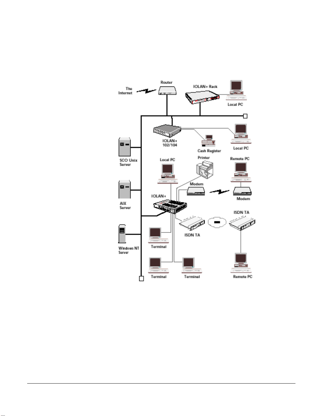
This configuration diagram shows many of the features available on the Terminal Server communications server:
NET
1
32 4
Terminal Server User Guide
About the Terminal Server
Chapter 1 Introduction
Page 25
Page 26

Terminal Server Features
Terminal Server is a TCP/IP communications server with 2, 4, 8 or 16, RS-232 or RS-422 ports for
making serial network connections. It attaches to your TCP/IP network and allows serial
devices such as modems, terminals and printers to access the network.
Hardware
The Terminal Server hardware features include:
• 2, 4, 8 or 16 serial lines, fully configurable with port speeds up to 115.2 kbps.
• RJ45 connectors on Terminal Server and 102/104 Terminal Server or DB25 connectors
on Terminal Server.
• Full modem control using DTR, DSR, CTS, RTS and DCD.
• FLASH memory for downloading firmware releases.
• 102/104 Terminal Server has 10BASE-T or 10/100BASE-T interfaces.
• Terminal Server and Rack Terminal Server have either autosensing 10BASE-T /
10BASE2 / AUI or 10/100BASE-T interfaces.
• Auto sensing power supply; 110-250V AC (48-60V DC option available on Terminal
Server ).
• LEDs for diagnostic testing.
• Self-test on power-up.
• Rack mount or tabletop design.
Terminal Server User Guide
Terminal Server Features
Chapter 1 Introduction
Page 26
Page 27

Software
The Terminal Server software features include:
• Support for TCP/IP and UDP protocols including telnet and rlogin.
• Remote access support including PPP, SLIP and CSLIP.
• Printer support via lpd, rcp, and utilities.
• Modem support via PPP and utilities.
• Utilities provide ‘fixed tty’ support for Unix systems.
• A window oriented menu interface with pop-up menus and on screen help (command line
also available).
• ARP or BOOTP for network based setup.
• Dynamic statistics displays and line status reporting for fast problem diagnosis.
• Multi screens on terminals.
• Full support of SNMP MIBs, allowing remote configuration via SNMP as well as statistics
gathering.
• Interoperability with IP routing through gateway tables.
• Domain Name Server support.
• WINS support for Windows ® environments.
• Port configuration copy and save functions.
Terminal Server User Guide
Terminal Server Features
Chapter 1 Introduction
Page 27
Page 28

Security
The Terminal Server security features include:
• Supervisory and port password.
• Port locking.
• Authentication with PAP support.
• Per user access level assignment.
• Service logging.
• Logging facility for audit and billing.
• Modem auto reset.
Terminal Server User Guide
Terminal Server Features
Chapter 1 Introduction
Page 28
Page 29
Hardware Overview
The following table and diagrams describe the units:
Model Type No. Ports Connector Interface
102/104 Terminal
Server
Terminal Server Table Top 8,16 DB25 RS232
Rack Terminal Server Rack Mount 4, 8, 16 RJ45 RS-232
Model
Table Top 2,4 RJ45 RS-232
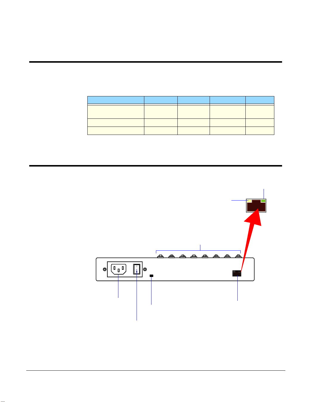
Hardware description for Terminal Server
10 BASE T Link/Activity
100 BASE T Link/Activity
Terminal Server User Guide
Hardware Overview
Power input socket
Main power switch
Power indicator
Page 29
Serial ports
10/100 BASE T socket
Chapter 1 Introduction
Page 30
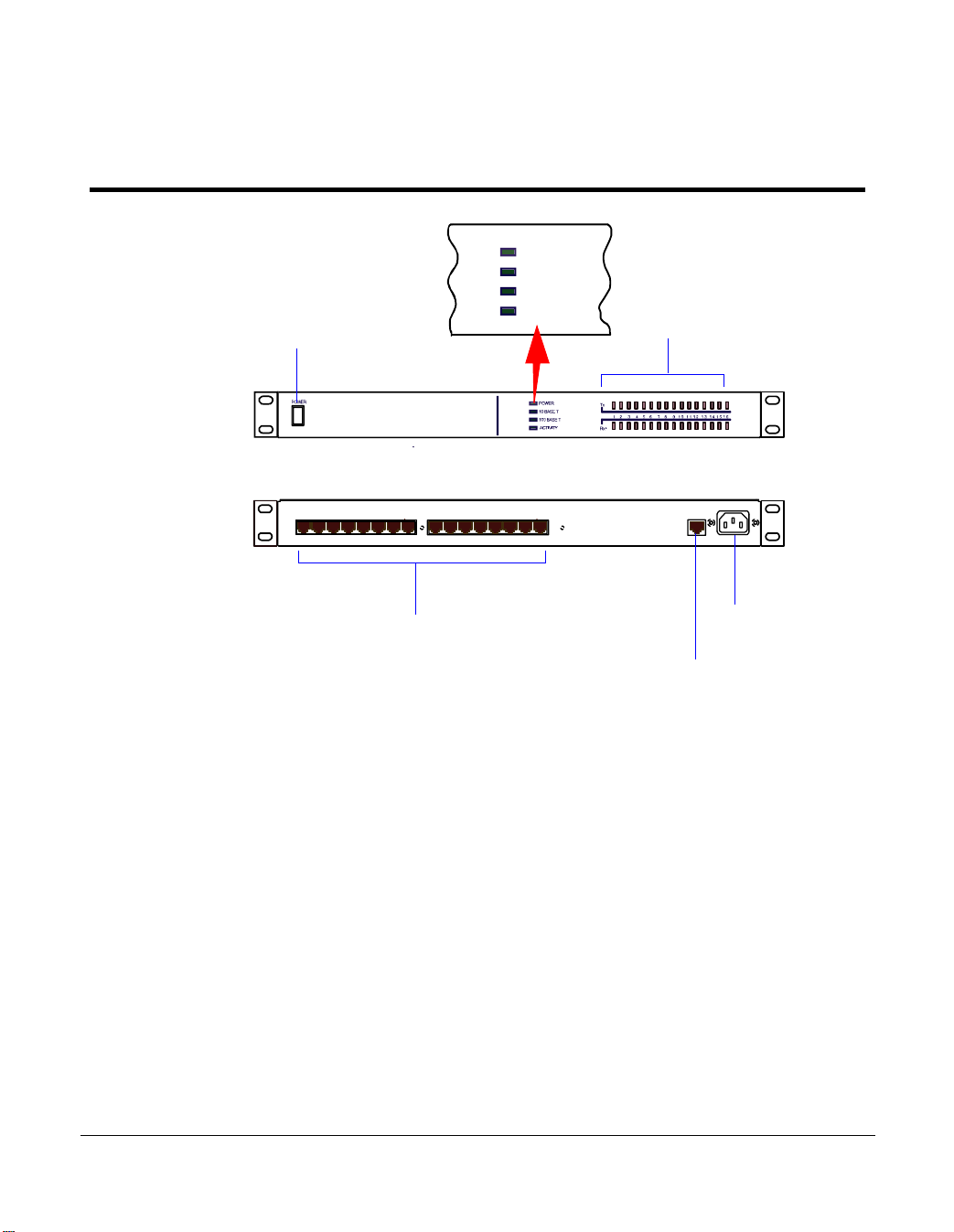
Hardware description for Rack Terminal Server
POWER
10 BASE T
100 BASE T
Main power switch
I
O
ACTIVITY
Port activity indicator
Serial ports
Power input socket
10/100 BASE T socket
Terminal Server User Guide
Hardware description for Rack Terminal Server
Chapter 1 Introduction
Page 30
Page 31

Hardware description for 102/104 Terminal Server
Network indicator
Power indicator
Serial ports
Port activity indicators
Power input socket
10/100 BASE-T socket
Terminal Server User Guide
Hardware description for 102/104 Terminal Server
Chapter 1 Introduction
Page 31
Page 32

Terminal Server
User Guide
Chapter 2 Installation
You need to read
this chapter if you
want to...
You need to read this chapter if you want information about installing your Terminal Server
product.
This chapter provides information about installing the Black Box Terminal Server including
connecting to your network, configuring communications as well as information on the menu
system and general tips.
This chapter includes the following sections;
• Connecting to your Network on page 33
• Switching on Terminal Server on page 34
• Communicating via ARP on page 35
• Communicating via a Terminal or PC on page 36
• The Menu System on page 37
• Tips on page 46.
Terminal Server User Guide
Chapter 2 Installation
Page 32
Page 33

Connecting to your Network
First connect Terminal Server to a network then begin configuring the unit for your
application. Additional information on configuring modems and printers follows.
Terminal Server and Rack Terminal Server connect to your ethernet network via one of the
following (depending on your hardware model):
• Auto-sensing 10BASE-T (twisted pair)
• Auto-sensing 10BASE2 (thin)
• Auto-sensing AUI
• 10/100BASET
102/104 Terminal Server connect using either:
• 10BASE-T (twisted pair)
• 10/100BASE-T
10BASE-T (twisted pair)
Attach the RJ connector from a hub directly to Terminal Server twisted pair port.
10BASE2 (Thin Ethernet)
AUI port
10/100BASE-T
Terminal Server User Guide
Connecting to your Network
Attach a BNC T connector directly to your Terminal Server. If your unit is the termination point
for the cable you need to add a terminator. Always ensure that each segment of the thin
Ethernet cable is at least 0.5m in length. The maximum length for a thin Ethernet cable is 185
metres.
The AUI connector allows an external transceiver to be connected. This allows a number of
different interfaces to connect including 10BASE5 (or thick) and fibre optic transceivers.
Attach the RJ45 connector from a hub directly to the Terminal Server port.
Attach the RJ connector from a hub directly to the Terminal Server 10/100BASE-T port.
Chapter 2 Installation
Page 33
Page 34

Switching on Terminal Server
The Terminal Server power supply accepts input voltages in the range 110 to 240V AC,
allowing it to be used world-wide. The 102/104 Terminal Server has an external power supply
unit.
After you connect your LAN interface, you can power up the unit. The green power indicator
at the side (or front for rack and 102/104 units) should be lit. If the unit fails to power up with
the green power indicator lit, disconnect the unit and contact your dealer for help.
The Terminal Server firmware may be compressed, and this takes a short time to
decompress before running.
During this phase the network LEDs will light alternately to indicate that decompression is in
progress.
The green Ethernet indicators show the active connections. It remains lit and blinks when
LAN traffic is active.
Note:
To change your Ethernet media, you will need to reboot the unit to activate the connector.
If your unit has 10BASE-T, 10BASE2 and AUI connectors, then the green ethernet indicators
show the active connection. The indicators remain lit and blink when LAN traffic is active.
If you have an Rack Terminal Server unit with 10/100BASE-T, then the Ethernet indicators
will light green to indicate either 10Mbit or 100Mbit link, and the Activity light flickers to
indicate LAN traffic.
If you have a Terminal Server or 102/104 Terminal Server with 10/100BASE-T, then the
Ethernet will light green to indicate a 100Mbit link, and orange to indicate a 10Mbit link. The
LED will flicker to show LAN traffic.
You are now ready to begin communicating with your Terminal Server. You can connect to
the unit in different ways: via a terminal or PC on port 1, or using ARP or BOOTP. Using ARP
is the preferred method for both Windows ® and Unix, however a terminal or PC attached to
port 1 is often used.
BOOTP setup is for Unix users only. Choose the appropriate method for your application.
Third party BOOTP packages are available for Windows ®
Terminal Server User Guide
Switching on Terminal Server
Chapter 2 Installation
Page 34
Page 35

Communicating via ARP
Your Terminal Server supports the ‘Address Resolution Protocol’ (ARP). It allows you to
temporarily connect to your Terminal Server to assign a permanent IP address. If you prefer
to use a terminal or PC attached to Terminal Server see Communicating via a Terminal or
PC on page 36.
To do this proceed as follows;
1. From a local Unix host, type the following:
arp -s a.b.c.d aa:bb:cc:dd:ee:ff
(where a.b.c.d is the IP address you want for Terminal Server, and aa:bb:cc:dd:ee:ff is the
Ethernet address of your Terminal Server, found on the bottom of the unit itself).
2. On a Windows ® NT/98 system, the arp command is slightly different (using dashes
instead of colons):
arp -s a.b.c.d aa-bb-cc-dd-ee-ff
3. Whether you use Unix or Windows ® to run arp, you are now ready to telnet to Terminal
Server. Here is the sequence to use:
arp -s 192.168.209.8 00:80:d4:00:33:4e
telnet 192.168.209.8
password>
local>
4. At the password prompt, press the Enter key since this is not set yet. The IP address still
needs to be configured on the unit (ARP has only allowed you to connect to the unit so
far).
You can now skip the next section and go straight to The Menu System on page 37
Terminal Server User Guide
Communicating via ARP
Note
If there are any errors, recheck both the IP and Ethernet addresses you
keyed in (this is the most common error here). See Appendix B
Troubleshooting for more information on problems.
Chapter 2 Installation
Page 35
Page 36

Communicating via a Terminal or PC
You can connect to Terminal Server using a terminal or PC (with a terminal emulation
package such as Hyperterm).
1. Connect a terminal or your PC to port 1. The Terminal Server serial ports are DTE type
RS-232 ports. When connecting a terminal/ PC directly (without modems), the RS-232
signals need to be crossed over (‘null modem’ cable). See Appendix D Cabling for
pinout information.
2. For a terminal/PC to communicate with a server, set it to the following: 9.6 kbps, eight
data bits, one stop bit, software flow control, no parity.
After powering up your Terminal Server, you are prompted to enter a ‘Local login:>‘.
3. You can just hit any character and at this point (the character is required).
The next prompt displayed is local>, which is the Command Line Interface (CLI) prompt.
Note
If there are any problems, check the cable you are using (this is the
most common error). Port 1 is configured to provide error messages
should any problems occur. See Appendix B Troubleshooting for
more information on problems.
You can now move to The Menu System. See The Menu System on page 37.
Terminal Server User Guide
Communicating via a Terminal or PC
Chapter 2 Installation
Page 36
Page 37

The Menu System
You should now be at the Command Line Interface (CLI) of the Terminal Server as
designated by the local> prompt. If you would like to continue in CLI mode refer to Appendix
A Command Line Interface, but we recommend the menu system.
1. Set the terminal emulation type and begin using the menus.
The following are the terminal options:
ansi, dumb, vt100, wyse50, wyse60, tvi925, ibm3151, vt320, falco50, hp700
2. The default setting is ‘dumb’. To set the menu interface to your emulation simply type set
term with your option.
Example:
local> set term ansi
3. To switch from the command line interface to the menu interface, at the local> prompt
enter:
set menu
Note
For Falco50 type local> set term falco
Terminal Server User Guide
The Menu System
Chapter 2 Installation
Page 37
Page 38

The Connections Menu should now be displayed.
This menu displays the current state of the four possible connections. There are no active
connections.
The firmware version of Terminal Server is located on the lower left hand portion. The
wording ‘REMOTE-ADMIN’ in the upper right signifies you are remotely telneted into
Terminal Server (and will read ‘Terminal: 1’ if you are using a terminal/PC into port 1.)
The keys used to move about in the menus depend on the terminal emulation you are using.
The arrow keys should all work. The TAB key is very important for moving between fields.
Backspace and DEL should work, but depend on the emulation.
ESC (the escape key) will move you back one menu.
An accelerator key can be used to jump to an option within a menu and is the first letter of the
option.
Terminal Server User Guide
The Menu System
Note
If there is a problem with your emulation, you can try a different
emulation mode. See Appendix B Troubleshootingfor more
information.
Chapter 2 Installation
Page 38
Page 39

Connections Menu
Select connection '1’ on the Connections Menu and press the Enter key. The Commands
pop-up menu is displayed. There are a number of options available from this menu.
Before communication across the network can be established the Terminal Server must be
assigned a network IP address. This is accessed through the Administration Menu.
Select the Admin mode field and press the Enter key.
Terminal Server User Guide
The Menu System
Note
If you are telneted into Terminal Server, the telnet, rlogin and port
options do not appear on the Commands pop-up menu.
Chapter 2 Installation
Page 39
Page 40

Administration Menu
The top level Administration Menu appears as follows:
1. Select the Password field and press the Enter key. Use the factory default password
here: this is iolan (no caps).
The Administration Menu is redisplayed, it now has some extra fields (access, change,
kill, reboot, trap).
Note:
This password level will time-out in four minutes if there is no activity. This is for security
reasons and will take you back to Administration Menu (view level).
Terminal Server User Guide
The Menu System
Chapter 2 Installation
Page 40
Page 41

2. Select the server entry and press the Enter key. This takes you into the Server
Configuration Menu.
Terminal Server User Guide
The Menu System
Chapter 2 Installation
Page 41
Page 42

Server Configuration Menu
There are a number of fields in the Server Configuration menu which are explained in
Chapter 10 The menu interface. At this point proceed as follows;
1. Give the Terminal Server an IP address and a name.
2. The important fields that you need to fill in are as follows:
3. Having filled in the fields press the Enter key. This brings the Commands pop-up menu as
Terminal Server User Guide
The Menu System
Name: In the example above the communications server name has been set to IOLAN. It
is a good idea for the Terminal Server name entered here to match the name entered in
the host machine’s domain name server.
Note
For more information about domain name servers, consult your
operating system manuals.
IP Address: This address must be set to a value that is consistent with the network the
Terminal Server is on.
shown in the next picture.
Note
The Ethernet address is factory set. This address is uniquely assigned
to the Terminal Server and MUST NOT be changed.
Chapter 2 Installation
Page 42
Page 43

4. Select the Save & Exit field and press the Enter key. Other options are Quit & Exit, which
does not save the changes before exiting this menu, Values, which will display the
optional values for this field if available, and Cancel, which will take you back to this
screen for more editing.
5. You have now set up the unit with a new IP address. This should be confirmed with the
message:
IP CHANGED—PLEASE REBOOT
6. Reboot the communications server to activate the new IP address using the reboot
command. The IP address and/or subnet mask are the only parameters that when
changed necessitate rebooting.
Terminal Server User Guide
The Menu System
Chapter 2 Installation
Page 43
Page 44

Port Setup Menu and Beyond
Your communications server is now ready to configure for terminals on multi-user systems or
modems, printers and other devices. The next sections deal with each of these.
If you’ve got a good feel for the menu system, you should proceed to the section appropriate
for your application.
If you’d like a full review of the menu system refer to section 9, The Menu Interface later in
this guide. For more information about the Command Line mode, consult Appendix A
Command Line Interface.
All of the procedures are based around the Port Setup Menu. This is accessed through the
Administration Menu (password level). Remember, that if you are not in the password level,
you can only view the information, not change it.
Here is the Port Setup Menu:
This menu allows the user to set up all the parameters associated with a port. The
administrator can alter the set-up of any port on the communications server while a user can
only alter the set-up for their own port.
Terminal Server User Guide
The Menu System
Chapter 2 Installation
Page 44
Page 45

This menu is divided into the following sections:
Menu option Description
Hardware Defines port type and is used for setting up the hardware configuration
of the modem, terminal, printer or PC session. This section is always
used.
User Defines various user parameters such as name and terminal type. Most
fields are used in this section.
Flow Control Defines the various flow control options used by the Terminal Server.
This section is always used.
IP Addresses Deals with remote access via PPP/SLIP sessions.
Options Deals mainly with the telnet options. This section is the least used.
Keys Defines the various accelerator keys that the Terminal Server responds
to and can be used for convenience.
Access Controls the type of the connection made from this port. This is the most
important section in defining a port.
If you’re ready to install terminals, printers and modems, proceed to the appropriate section.
For a good review, go to Chapter 10 The menu interface.
Terminal Server User Guide
The Menu System
Chapter 2 Installation
Page 45
Page 46

Tips
Copy Command
The Terminal Server has a copy command that allows you to copy the setup of one port to
another. You will need to get to the CLI (from the Connection menu) and use the following
syntax.
Note:
To get back to the menu system once in the CLI, type set menu at the command line.
local> su
password>
ADMIN:local> copy 1 2 3 4 5
ADMIN:local> set menu
The commands above would copy the configuration of port number 1 to ports 2, 3, 4 and 5
(and return you to the menu system).
Connecting via BOOTP (for Unix systems only)
Your Terminal Server supports BOOTP which allows the communications server to
dynamically configure itself on startup. Upon startup your Terminal Server sends four BOOTP
broadcast requests if it has no IP address. This broadcast request packet contains the
Ethernet address of your unit.
The request is received by all hosts on the network and is checked against a file to find a
match. This data base file will normally be /etc/bootptab and will be of the following format:
Where:
ht is the type of network
ha is the Ethernet address on back of your unit
Terminal Server User Guide
Tips
# bootptab description
iolan:ht=ethernet:ha=0080d400024e:\
:hd=/tftp:\
:bf=iolan.DL:\
:ip=192.168.209.8:
Chapter 2 Installation
Page 46
Page 47

hd is the home directory for specifying Terminal Server firmware (optional)
bf is the name of Terminal Server firmware (optional)
ip is the IP address you want to use
Note
This BOOTP implementation is a subset and not a full implementation of the RFC.
Note
The most common error is bad information in the /etc/bootptab file (recheck it).
See Appendix B Troubleshooting for more information.
You can now move back to The Menu System in this chapter.
Terminal Server User Guide
Tips
Chapter 2 Installation
Page 47
Page 48

Saving and downloading configurations
It is possible to save the configuration of your Terminal Server. This is convenient for loading
multiple communications servers with the same setup. It is also advisable as a backup
method.
If the boot file name has the extension “.cfg” (eg iolan.cfg), it will be loaded as a configuration
file rather than a boot file.
This allows the administrator to configure one Terminal Server, save its configuration and
automatically configure subsequent units via bootp.
Should the configuration of your Terminal Server ever be corrupted because of user error or
damage, it is an advantage to have the configuration stored somewhere for easy reinstallation.
This can be achieved by uploading the configuration of the unit to a host on the network. To
do this, enter the Communications Server Menu from the Administration Menu. Select the Init
file entry of this menu.
Set this to the full pathname of the file in which you wish to store the configuration. Set Boot
host to the host machine you wish the file to reside within and save these entries.
Boot host: rockvegas (or ip address)
Init file: /tftp/term_serv.cfg
Log onto the host machine in the normal manner and create the file you have specified in the
Terminal Server menu, this could be as shown in the next picture:
touch term_serv.cfg
Terminal Server User Guide
Tips
Note
This file must exist with the correct read/write permissions before you can write to it.This
can be accomplished by pressing the Enter key and selecting the CLI option in the pop
up menu. At the iolan> prompt, use the CLI as the administrator by typing:
su
and enter the password and type:
save config
This uploads the communications server port configurations to the host in a format that
can be downloaded at a later date.
Note
This does not save any of the settings configured in the Server Configuration Menu,
including the IP address, language, name, subnet mask, etc.
Chapter 2 Installation
Page 48
Page 49

Terminal Server will now automatically download this configuration on reboot. Remember
that whenever you change a setting on the unit, it will be overwritten the next time the unit is
rebooted unless the new configuration is saved.
Domain Name Server (DNS)
Terminal Server can be configured to take advantage of your network’s Domain Name Server
(DNS). This is done from the server in the Administration Menu by keying in the IP address of
your DNS in the Name server field. Fill in the Domain name field as well.
Reassigning your Terminal Server to a New Network
If you need to attach your Terminal Server to a different network with a new IP address, it is
possible to reset it to factory default condition using the following procedure:
1. Power on the unit.
2. Wait 30 seconds.
Note
If firmware is compressed, then network LED will alternately light for
approximately an additional 30 seconds.
3. Hold down the RESET button for 15 seconds.
4. Release the button.
After this is done, the unit will start sending BOOTP request packets.
This procedure is useful for factory defaulting units which cannot be reached via TCP/IP. This
includes reassigning a programmed unit to a network to which the previously assigned IP
address does not belong.
Updating Terminal Server Firmware
Firmware can be downloaded across the network using tftp protocol if the host machine and
file name are set in the boot host and boot file entries of the server menu. These entries are
checked at start up and if they have been configured, the relevant file will be downloaded.
Note:
tftp must be enabled on the relevant host as it is disabled by default
Terminal Server User Guide
Tips
Chapter 2 Installation
Page 49
Page 50

Terminal Server
User Guide
Chapter 3 Terminals on mutli-user systems
You need to read
this chapter if you
want to...
You need to read this chapter if you want information on setting up a terminal for use with
your Terminal Server product.
This chapter provides information on how to setup a terminal, and other tips such as the
concept of ‘fixed ttys’, multiscreens, the copy command, TERM features, etc.
This chapter includes the following sections;
• Introduction on page 51
• Terminal Port Configuration on page 52
• Host Table Setup on page 54
• Making a Connection on page 55
• Tips on page 57
Terminal Server User Guide
Chapter 3 Terminals on mutli-user systems
Page 50
Page 51

Introduction
Terminal Server is used extensively for connecting terminals, printers and modems on multiuser Unix systems, especially in retail applications. These Unix systems include SCO Unix,
IBM AIX, HP-UX, Data General’s DG/UX, etc. This chapter deals with terminals and/or PCs
using emulation packages (such as Hyperterm).
In many applications, the users need to be ‘direct connected’ to a specific Unix host so that
they see the login prompt automatically. This is helpful in securing your system, or in
environments where the users need to be in one application only.
This chapter will show how to setup a terminal, and other tips such as the concept of ‘fixed
ttys’, multi screens, the copy command, TERM features, etc. Consult Appendix D Cabling,
for information on wiring your terminal.
Remember to use the TAB key to bounce between fields, and if you get the Commands exit
menu by mistake, use Cancel to return to editing this menu.
Terminal Server User Guide
Introduction
Chapter 3 Terminals on mutli-user systems
Page 51
Page 52

Terminal Port Configuration
This is the setup for making a terminal connect to a designated Unix host login prompt
automatically.
The following fields are important:
Terminal Server User Guide
Terminal Port Configuration
Menu
option
Access Set this field to Local. This tells the terminal server port to listen for data
Mode With this field set to telnet, the port will operate in telnet mode (or raw for
Connection Set this field to Initiated and the port will establish a TCP/IP connection to
Host Use this field to define which host computer you want the port to
Description
on the RS-232 side.
rlogin). Most systems will use telnet.
a specified host only after receiving a <CR> on the RS-232 port. If you
set this field to none, then the user of this port will see the menu system
when the terminal is powered on.
automatically connect to when using Initiated connections. Use the host’s
IP address or if you setup the Host Address Menu, you can use a name.
Chapter 3 Terminals on mutli-user systems
Page 52
Page 53

Menu
option
Description
Remote Port This corresponds to Telnet service on the remote host and must be set to
the standard 23 (or 513 for rlogin).
Monitor DSR You can set this field to Yes if you wire the terminal’s DTR signal pin 20
(DB25) to the Terminal Server's DSR signal pin 3 on the RJ45 connector
( see Appendix D Cabling for DB25 pin assignments). When you turn
the terminal off, it will reset the Terminal Server port, which tells the Unix
host to kill the user’s processes.
Terminal Server User Guide
Terminal Port Configuration
Chapter 3 Terminals on mutli-user systems
Page 53
Page 54

Host Table Setup
In order for your Terminal Server to connect easily to machines on the network it must know
the IP addresses of the other computers. The Terminal Server can have its own internal table
of IP addresses set up in the host table. This is a ‘local’ naming system only. Your Terminal
Server can also use the name server utility of your Unix system (consult your Unix system
manual and Tips on page 57).
The Host Address Menu is accessed from the Administration Menu by selecting the host
entry. The host table can contain up to 10 addresses. Each entry consists of a host name and
its corresponding IP address.
You can fill in an entry (both the name and the IP Address) for your host machines and then
save the values by pressing the Enter key.
Terminal Server User Guide
Host Table Setup
Chapter 3 Terminals on mutli-user systems
Page 54
Page 55

Making a Connection
If you are using initiated connections, you will not see the Terminal Server menus. Instead,
you see the login prompt of the host you assigned in the host field of the Port Setup Menu.
However, if your connection field is set to None, the Connections Menu appears. You are
now ready to make connections. From the Connections Menu press the Enter key on a ***
FREE *** session to display the Commands menu. Select the Telnet field and press the Enter
key.
This produces a pop-up menu allowing the choice of the host machines that are configured in
the host table. To select a host, move the cursor down to the required name then press the
Enter key. At this point the unit attempts to make a connection across the network to the
indicated host using the telnet protocol.
If it succeeds, the host machine’s login prompt is displayed. There may be an error in the
configuration if the connection cannot be established.
While in session to the host machine, you can return to the communications server by using
a hot key. This is user-defined, but defaults to ^]. Press this key and the Connections Menu is
displayed. To resume your connection select the host session you were on (notice that the
Terminal Server User Guide
Making a Connection
Note
At this point, check the host table again for correct entries, then check the network connection
and host machine you’re connecting to.
Chapter 3 Terminals on mutli-user systems
Page 55
Page 56

name of the host is now displayed where *** FREE *** was). Press the Enter key to bring up
the Connection pop-up menu, then select the Resume Connection option.
Note
If the ^] did not work, you might have a conflict with that character sequence and
should check the Keys section of this port.
When logging out of your session the connection is automatically closed.
Terminal Server User Guide
Making a Connection
Chapter 3 Terminals on mutli-user systems
Page 56
Page 57

Tips
Connecting via ‘fixed ttys’
Your Terminal Server has the ability to create a ‘fixed tty’ under Unix. This is helpful for older
or secure Unix applications that require a fixed location for each terminal. Consult Chapter 9
Other devices setup.
Multisessions on terminals/PCs
Your Terminal Server is capable of supporting multiple sessions. This allows the user to
connect to all four *** FREE *** sessions with different hosts and move between them using
the ^] hot key. You can also key through the screens by setting the session key (that is, If set
to ^A you would bounce through the screens with a ^A1, ^A2, ^A3, ^A4.). If you are using a
terminal that supports video pages such as the Wyse 60, the screens will be refreshed if you
set the video pages field on the Port Menu to the number of pages supported by your
terminal (for Wyse 60 = 3).
The TERM field The TERM field in the Port Setup Menu can be used to pass the terminal
type information to the host. The terminal type field is local to the Terminal Server but will be
passed to the host.
The TERM field can override the information being sent to the host about the type of
terminal. This allows you to customise information being passed to the host. For example, a
user could encode the physical location into this field (that is, tty16) and then extract that at
the host end to determine which port the user has logged in on (that is, port 16).
Gateway Tables
When the host and Terminal Server are connected via a gateway router, a connection is not
possible until the gateway table has been updated with the IP address of the local gateway
machine. See Gateway Menu on page 149 in Chapter 10 The menu interface.
Terminal Server User Guide
Tips
Chapter 3 Terminals on mutli-user systems
Page 57
Page 58

Terminal Server
User Guide
Chapter 4 Setting up dial-in modem ports
You need to read
this chapter if you
want to...
You need to read this chapter if you want information on creating dial-in connections with
your Terminal Server product.
This chapter provides information on the configuration necessary to create dial-in
connections. It includes the most simple connection such as a dial-in Unix connection, The
setting up PPP ports which is how Windows ® systems dial-in (as well as Unix).
This chapter includes the following sections;
• Introduction on page 59
• Dial-in Port on page 60
• The host on page 62
• The modem on page 63
• Client login on page 64
• Tips on page 65.
Terminal Server User Guide
Chapter 4 Setting up dial-in modem ports
Page 58
Page 59

Introduction
This chapter will review the configuration necessary to create dial-in connections. It will start
with the most simple connection such as a dial-in Unix connection. The chapter then moves
into setting up PPP ports which is how Windows ® systems dial-in (as well as Unix). This is
very important if you are an Internet Service Provider (ISP) or a corporate site providing
remote access or Internet/Intranet access.
Your Terminal Server can make a very good dial-in solution for ISPs and corporate users
alike by using its remote access facilities.
This chapter goes hand-in-hand with Chapter 5 Modem authentication and logging.
Note
In many of the modem examples, we are using PPP. You can use SLIP
and CSLIP in those applications requiring these legacy modes.
Terminal Server User Guide
Introduction
Chapter 4 Setting up dial-in modem ports
Page 59
Page 60

Dial-in Port
The following is the port configuration for a dial-in connection, including PPP.
The following fields are important:
Terminal Server User Guide
Dial-in Port
Option Description
Monitor DCD With this flag set to Yes, your Terminal Server will monitor Data Carrier
Detect (DCD) - pin 8 - from the modem. As soon as your modem
answers a call and establishes a carrier signal, the modem raises DCD.
The terminal server will then establish a telnet/rlogin connection to a
specified host. When the modem hangs up, DCD goes low and the
terminal server port resets. This will also drop the connection to the host.
TERM This field is the TERM environment variable.Whatever you type in here
will be passed to the host as the TERM variable when a telnet
connection is established and the user logs in.
Flow Ctrl The modem and terminal server port should be configured to use
Hardware (RTS/CTS) flow control. This will be especially important if you
are using SLIP.
Chapter 4 Setting up dial-in modem ports
Page 60
Page 61

Option Description
Dst: This field contains the IP address the dial-in user will borrow for the PPP
session. If you are using a straight forward dial-in connection for Unix,
this is not required.
Mask If using PPP, SLIP or CSLIP, this is the subnet mask that controls the
range of IP addresses accessible from the port and must correspond
with your network. (If used for terminals, this is not needed.)
Secure This field is set to Yes to force the call-in user to use the Dst IP address.
(su is not available in this mode.) If the Secure flag is set, the dial-in user
will not be able to obtain administrative privileges. This also applies to
local terminals.
Access Set this field to Dynamic. This sets the port of the terminal server
to listen for data on both the RS-232 side and the network side. If
only used for dial-in, set to Local and it will only listen on the RS232 side.
Connection With the connection set to Dedicated, the port will automatically
connect to a specified host when not doing PPP (DCD goes high
on the modem).
Host When not doing PPP, this field defines which host computer you
want the port to automatically connect to. Use the host’s IP
address. You can also define the host in the terminal server’s Host
Table and just use the name.
Remote
port
This corresponds to the Login (for example, rlogin) service on the
remote host and must be 513 (or 23 for Telnet).
Local port The inetd process running on the terminal server for this port is
listening for TCP/IP connections on TCP port 10006.
Terminal Server User Guide
Dial-in Port
Chapter 4 Setting up dial-in modem ports
Page 61
Page 62

The host
Make sure you have setup a valid user account for authentication on the designated
authentication host. See Chapter 5 Modem authentication and logging.
Terminal Server User Guide
The host
Chapter 4 Setting up dial-in modem ports
Page 62
Page 63

The modem
You will need to configure the modem using a configuration string. To do this, go to the
Remote Site Devices screen (via the Access section of the Administrative Menu). Select the
UNUSED ENTRY that corresponds to the port with the modem attached (that is, third one
down is port 3, etc.). You can set the type (for example, name) and the Modem Config to the
required configuration string (for example, ate0s0=1&w). All other fields are default.
You will now need to kill this port (from the Administration Menu or CLI) to activate the
changes and configure the modem.
The configuration string will be sent to the modem after each call, keeping the modem in
sync with Terminal Server.
Terminal Server User Guide
The modem
Chapter 4 Setting up dial-in modem ports
Page 63
Page 64

Client login
When the caller connects, you may want to send out a welcome message of some sort. After
the user gets this message, you want him/her to enter a login and password then connect to
the Host for a shell account.
Or, if it is a PPP user, they will simply start sending PPP packets at the login prompt (for
example, Windows ® 95/98) and use PAP for authentication. Optionally, the dial-in user can
place a P, S or C (all caps) in front of the user name at the Login prompt (this starts the
corresponding protocol after successful authentication).
With this example, the Terminal Server is now in CSLIP mode, so put your PC into CSLIP
mode as well. Your dialer script will have to parse out the My/Your addresses from the above
message.
‘Your IP Address’ will be the address of the PC that is calling in, and ‘My IP Address’ can be
the PC’s default gateway. The above procedure works for SLIP and PPP as well. However,
PPP will not display the ‘My IP...’ message because the IP addresses are negotiated
automatically in the IPCP layer.
Welcome to the Internet site
login: Cflint
password:
Host authentication succeeded.
My IP Address is : 204.17.209.7
Your IP Address is : 204.17.209.210
The Subnet Mask is : 255.255.255.0
With the Connection field on the Port Setup Menu set to Dedicated, if you do not specify a P,
S or C in front of the user name, you will be authenticated and then connected to the host.
This will leave you at a shell prompt on the Authentication host. A caller will never see
Terminal Server. If Connection is set to None, you will be left at the CLI prompt (for example,
IOLAN> ).
Terminal Server User Guide
Client login
Chapter 4 Setting up dial-in modem ports
Page 64
Page 65

Tips
Domain Name Server (DNS)
Your Terminal Server can be configured to take advantage of your network’s Domain Name
Server (DNS). This is important for ISPs. From the Administration Menu select server and
key in the IP address of your DNS in the Name server field. You could fill in the Domain name
field as well.
WINS Server
If you have a local NT server running WINS and you want dial-in clients to take advantage of
that, put the IP address of the NT server in the WINS server field of the Server Configuration
screen.
Note
The Windows ® 95/98 client obtains the WINS address by setting 'Use DHCP for WINS
resolution'.
MOTD
A Message of the Day (MOTD) can be displayed before login. This is setup from the Server
Configuration menu using MOTD and Boot host fields.
Gateway notes
If you have a router on your local network, make sure you enter this into the Terminal Server
Gateway Menu.
Terminal Server User Guide
Tips
Chapter 4 Setting up dial-in modem ports
Page 65
Page 66

Terminal Server
User Guide
Chapter 5 Modem authentication and logging
You need to read
this chapter if you
want to...
You need to read this chapter if you want information on modem authentication and logging
for your Terminal Server unit.
This chapter contains information providing authentication support to validate users
connecting to the serial port, and updating a host log file on connection states.
This chapter includes the following sections;
• Introduction on page 67
• User authentication/logging on page 68
• The host on page 71
• Logging on page 73
• Tips on page 74
Terminal Server User Guide
Chapter 5 Modem authentication and logging
Page 66
Page 67

Introduction
Your Terminal Server provides authentication support to validate users connecting to the
serial port, and can update a host log file on connection states. Authentication and logging is
achieved by using a designated authentication host to validate users and keep connection
information. This unique facility takes the burden away from the unit and more importantly
allows the administrator to configure one host, rather than configuring multiple terminal
servers.
Option Description
Authentication When the Terminal Server port has authentication set to
host or both, the user is required to enter a user name
followed by a password when dialed in. The user ID and
password are forwarded to the authentication host for
validation. By setting the authentication hosts network port
to 23 or 513, this allows the user ID to be checked against
the standard Unix login system (see Tips on page 74). This
feature also allows proprietary user validation code to be
written on any TCP/IP platform by choosing another
network port number.
Logging During the Terminal Server start up, a telnet session is
established to the authentication host, with the pre-defined
Log Username and Logger password. Serial events like
users logging in and out are recorded in the defined Log
File.
The Host Authentication And Logging menu may be accessed via the administrator from the
access option in the Administration Menu.
Terminal Server User Guide
Introduction
Note
RADIUS is often associated, but not required, for dial-in services. RADIUS offers three
major functions: authentication, logging and user services. Terminal Server can be
configured to offer all of these features but without using RADIUS. This section explains
how.
Chapter 5 Modem authentication and logging
Page 67
Page 68

User authentication/logging
To improve access security, the Terminal Server has a mechanism for authenticating users
before allowing them access. This is accomplished by prompting the user for a Login ID and
a password. The Terminal Server will then attempt to login to a specified host using that ID
and password. If successful, the user is authenticated and allowed access. Otherwise, the
call is dropped. Your Terminal Server will also log events such as logins, logouts, connections
and disconnections, and power ups.
This feature is enabled when you set the Authentication field to host in the Port Setup Menu.
The following is the host authentication setup (via the Access section of the Administration
Menu):
The following fields are important:
Terminal Server User Guide
User authentication/logging
Chapter 5 Modem authentication and logging
Page 68
Page 69

Option Description
Auth Host The IP Address/Name of the host that the Terminal Server
attempts to login to for authenticating users.
Authentication Port The TCP service to be used for authenticating users.
Normally this is set to 23 for Telnet.
Login Prompt The string used by the Terminal Server to know when to
send the login ID. Set this field to ogin:. Leave out the first
letter as some systems use a ‘L’ and others use a ‘l’ as the
first letter.
Password Prompt The string used by the Terminal Server to know when to
send the users password. Use ‘ssword’ as depicted above.
Success Indication String The string used by the Terminal Server to determine if the
login ID and Password were valid and the login process was
successful. Normally you will see the string ‘Last’ after
successfully logging in.
Failure Indication String The string your Terminal Server will look for to determine
that the Login ID or Password were invalid. You will normally
see the word ‘invalid’ or ‘incorrect’ as part of the failure
message from the host.
Maximum Login Attempts The number of login attempts your Terminal Server will allow
the user to make before dropping the call.
Login Timeout This defines the amount of time in seconds the Terminal
Server will wait for the user to provide a login ID and
password before dropping the line.
Disconnect Probe This option determines whether authentication probe logins
will be terminated on completion of authentication.
Log Username The User ID your Terminal Server will use to log in to
the authentication host and log messages. This user
needs to be at a shell prompt to ‘cat’ messages to the
log file. The password for the log user is set up under
the Terminal Server Administration Menu -Change
option. Then choose the Logger option and enter the
log user’s password as defined on the host. You will
have to enter this password twice. (See Tips on
page 74.)
Log File The filename the log user will send itsmessages to.
Normally this will go to the log user’s home directory.
Log Power Up/Down The Terminal Server will log when it is powered up and
rebooted.
Log User Login/Logout The Terminal Server will log when a user logs in and
out of a port on Terminal Server.
Terminal Server User Guide
User authentication/logging
Chapter 5 Modem authentication and logging
Page 69
Page 70

Option Description
Log Port Connect/
Disconnect
Log User Service Start/
Stop
The Terminal Server will log when someone connects
to and disconnects from a port on Terminal Server.
The Terminal Server will log a PPP, SLIP or CSLIP
service when started on the port.
Terminal Server User Guide
User authentication/logging
Chapter 5 Modem authentication and logging
Page 70
Page 71

The host
Basic authentication
Your Terminal Server will need to login to the authentication host with the log user name
defined on the Host Authentication And Logging screen. Therefore, you need to create an
account to be used by Terminal Server (avoid csh shell). Make sure the user can log in
successfully. Also, make sure the user is not prompted for any input and ends up at a shell
prompt.
User services authentication
This is used to provide services based upon the dial-in user’s name.
For example, user Mark always telnets to a specific IP address or user Alan needs to dial-in
and establish a PPP connection using a static IP address. This is accomplished by using a
PERL script which parses a RADIUS database. The PERL script ( RADparse) is on the CD or
our website.
RADIUS is the TCP/IP protocol used for authenticating remote dial-in users. Although
Terminal Server does not use RADIUS, a Perl based utility capable of using standard
RADIUS databases is available.
Otherwise, you can execute our PERL script during the user’s login. Under Unix, this script is
started from the etc/profile.
You then need to create a user database file. This is a sample file.
Terminal Server User Guide
The host
# Example of a PPP user with static address
alan Password
Framed-Protocol = PPP
Framed-Address = 204.17.209.1
# Example of a user with access to Terminal Server
CLI/Menu
techman Password
User-Service-Type = Shell-Use
# Example of a telnet user
mark Password
User-Service-Type = Login-User
Login-Host = 208.24.183.1
Login-Service = Telnet
Chapter 5 Modem authentication and logging
Page 71
Page 72

# Everybody else gets PPP with a dynamic address
DEFAULT Password
Framed-Protocol = PPP
Note
When using advanced authentication, make sure the Success Indication String in
the Host Authentication And Logging menu is set to userdefined.
Terminal Server User Guide
The host
Chapter 5 Modem authentication and logging
Page 72
Page 73

Logging
A log file can be updated on the authentication host to record when a Terminal Server is
powered up, rebooted, and users and ports are connected and disconnected. This
information is of particular importance to administrators who need to record users logging in
and out. In addition, when the logger is enabled the Terminal Server completes a time stamp
every 5 minutes to record that the Terminal Server is still active. This allows an administrator
to gain an accurate record of events.
See User authentication/logging on page 68 (via the Access section of the Administration
Menu).
When the Terminal Server is powered up a Telnet connection is established to the
authentication host with the Logger user name. The Terminal Server records users logging in
and out of the log file access.log. The logger only connects at Terminal Server start-up time
and the connection stays open until the unit is reset. The Terminal Server checks the log TCP
connection every 60 seconds. The logger may be restarted via the kill command by adding
two to the number of ports on your server (for example, use four for an Terminal Server2, six
for an Terminal Server4, ten for an Terminal Server8, eighteen for an Terminal Server16). If
the host authentication succeeds, but logger fails to log events, then the port connection is
dropped.
Terminal Server User Guide
Logging
Chapter 5 Modem authentication and logging
Page 73
Page 74

Tips
Windows ® notes Authentication of Windows NT ® requires a telnet daemon. Check the Windows ® section of
our website for the latest Windows ® telnetd software. You will need to set up your users on
Windows NT ® through this software.
Logging on Windows NT ® also requires a utility called log_it.exe. If the Windows NT ® login
user id is ‘logger’, enter it into the Terminal Server as Nlogger so that the Terminal Server will
know to use the log_it.exe utility.
Also, on the Host Authentication And Logging menu, change the Terminal Server Success
Indication String to read, Microsoft instead of Last.)
Unix notes For LINUX users, edit the file /etc/motd and put the word ‘Last’ in it. This will agree with the
standard setup of the Host Authentication And Logging menu’s Success Indication String.
Terminal Server User Guide
Tips
Chapter 5 Modem authentication and logging
Page 74
Page 75

Terminal Server
User Guide
Chapter 6 Dialout modem ports setup
You need to read
this chapter if you
want to...
You need to read this chapter if you want information on setting up modem ports for your
Terminal Server product.
This chapter provides on setting up modem ports for your Terminal Server product. Dial-out
ports can be just a simple Unix outbound cu call or your Terminal Server can act as a dial-out
router to facilitate Internet PPP requests.
This chapter includes the following sections;
• Introduction on page 76
• Configuration on page 77
• The host on page 78
• Routing on page 79
• Remote Access Systems on page 80
• Remote site devices on page 83
• Tips on page 84.
Terminal Server User Guide
Chapter 6 Dialout modem ports setup
Page 75
Page 76

Introduction
Dial-out ports can be just a simple Unix outbound cu call or your Terminal Server can act as a
dial-out router to facilitate Internet PPP requests.
As a dial-out router your Terminal Server automatically establishes a PPP/SLIP/CSLIP link to
that site. Then drops the call after a preset period of inactivity. This dial-on-demand feature is
automatic. Your Terminal Server will place the call when local TCP/IP traffic needs to be
routed to a configured remote site.
If not using dial-out routing, you will need a COMPORT redirector such as ioland. The CD
has the ioland utility if you are using Unix. Please load the appropriate binary onto your
system. If you can not find the correct binary, please compile the ioland.c source code for
your system (see your Unix manual).
Terminal Server User Guide
Introduction
Chapter 6 Dialout modem ports setup
Page 76
Page 77

Configuration
The Port Setup Menu should be set up as follows for both simple dial-in connections and
PPP/SLIP connections.
The following fields are important:
Terminal Server User Guide
Configuration
Field Description
Access Set the Access field to Dynamic (dial-in or out) or Remote (dial-
out only).
Monitor DCD With this flag set to Yes, the terminal server will monitor the
modem signal Data Carrier Detect (DCD) - pin 8. When the
modem hangs up, pin DCD from the modem goes low and the
terminal server port will reset.
Flow Ctrl The modem and terminal server port should be configured to
use Hardware (RTS/CTS) flow control. This will be especially
important if you are transferring binary files.
Mode Set this field to raw.
Chapter 6 Dialout modem ports setup
Page 77
Page 78

The host
For dial-out connections on Unix
If you have not already loaded ioland onto your system, do so now (see CD). For more
information on ioland see Chapter 9 Other devices setup. In it’s simplest form, at the
superuser prompt you would run the following command in Unix:
ioland –h <server-name> 10006 <device-name>
This will start the ioland process and allow you to specify a device-name in /dev that is linked
to a pseudo tty. This pseudo tty works just like a regular tty with the following exception: you
cannot set physical attributes such as baud rate, parity and flow control as these are handled
by the terminal server. If you plan to use communication software on the Unix host such as
cu or uucp you should refer to your Unix manual for additional help.
For dial-out connections on Windows ® systems
Check our website for the latest information on dial-out connections (under the Windows ®
support ).
Terminal Server User Guide
The host
Chapter 6 Dialout modem ports setup
Page 78
Page 79

Routing
For dial-out routing, you must have the proper routing entry on all hosts in your local network
that will communicate with the remote site. In the case of a Unix system, you must make an
entry similar to the following (please check your Unix manual for the proper syntax of the
route command):
For a single host at the remote site:
route add <remote-ip-addr> <IOLAN-ip-addr> 2
For multiple hosts at the remote site:
route add net <remote-net-addr> <IOLAN-ip-addr> 2
The Terminal Server will dial into another piece of hardware, log into that hardware and start
a PPP session. Then the local Terminal Server will act as a router and forward all IP traffic
destined outside its local network. In other words, the Terminal Server will 'auto-dial' the
Internet and act as the router. In this example, the local network is: 206.131.227.0, the ISP’s
network is: 206.189.134.0, the ISP’s equipment that you are dialing into is another Terminal
Server (206.189.134.7) and the local Terminal Server is: 206.131.227.5. The Terminal Server
gateway entries look like this:
Terminal Server User Guide
Routing
Chapter 6 Dialout modem ports setup
Page 79
Page 80

Remote Access Systems
This screen is used to define a remote system (up to 16 entries per unit), a phone number,
login script, etc. There are a lot of similarities between this screen and the UUCP systems file
under Unix.
The following fields are important:
Terminal Server User Guide
Remote Access Systems
Chapter 6 Dialout modem ports setup
Page 80
Page 81

Field Description
Sitename The IP name or IP address of the remote site Terminal Server will be
calling.
User name The user name required by the remote system for logging in. You
may use the \u in your login script in lieu of the full name.
Password The above user name’s password as required by the remote system.
You may use the \p in your login script in lieu of the full password.
Device type The name of the modem device as defined in the Remote Access
Systems Screen. You may have several ports setup with the same
device type, and the dialer will use the first available. If a device for
dialling out is not available, the Terminal Server will return an ICMP
‘host unreachable’ message (ICMP type 3 code 1).
Service type: This specifies which protocol will be used when the link is established
to the remote site. Choices are PPP, SLIP and CSLIP.
Inactivity The period (in minutes) of inactivity on the SLIP/ PPP link before the
port drops the call automatically. Setting this field to 0 turns the
timeout feature off.
Phone number The phone number of the remote system. Note that the ‘\’ may be
used as a delay. For example, a phone system that requires a 9
followed by a four-second delay before getting an outside line would
require an entry like 9\4-2145551234.
The following
when included as part of the number.
characters are ignored
‘(‘, ‘)’, ‘-’, ‘.’
Login-script The chat script that will be used to login to the remote system. It takes
the form of the usual Send/Expect chat script you may already be
familiar with. If no script is defined, this step is skipped (for example,
hardwired connections). There are a few special characters used by
the Terminal Server as described below:
"" expect nothing (for example, the Terminal Server starts the chat
script)
\r send a carriage return
\n send new-line
\u user name (sends the username from the User name field).
\p password (sends the password from the password field).
\1-\9 delay for number of seconds.
\s space (Substitute this instead of a <space> value).
\t phone# (sends the telephone number field).
\d send the modem’s dial command
\\ escapes to ‘\’.
\b send a break.
Terminal Server User Guide
Remote Access Systems
Chapter 6 Dialout modem ports setup
Page 81
Page 82

Dial-out PAP Authentication
If a dial-out script is not used but a username and password are defined, your Terminal
Server will send a PAP packet after establishing a PPP link and use the username and
password defined for the remote site.
Terminal Server User Guide
Remote Access Systems
Chapter 6 Dialout modem ports setup
Page 82
Page 83

Remote site devices
This screen is used to define/setup the modem device. There are a lot of similarities between
this screen and the UUCP devices file under Unix. It is possible to assign several ports the
same device name, and the dialer daemon will automatically use the first available port. It is
also possible to have these ports do ‘double-duty’ and serve as regular dial-in ports for dumb
terminal access, SLIP or PPP in addition to the dial-out capability.
The following fields are important:
Terminal Server User Guide
Remote site devices
Field Description
Typ e The name of the modem assigned to a specific port. It is
referenced from the Remote Access Systems Screen in the
Device type field.
Dst Address The address of the remote system your Terminal Server is calling
into.
Config The modem’s configuration string. There are a few examples at
the end of this document.
Note: Leave this field blank for directly connected devices.
Restart timer Amount of time in seconds before the Terminal Server retransmits
PPP options.
Chapter 6 Dialout modem ports setup
Page 83
Page 84

Field Description
Max Retries Number of option retries before dropping the line.
Dial Timeout Number of seconds to wait for the modem to establish link and
respond.
Dial Retries Number of times to attempt a connection to the remote site before
giving up.
Tips
Hunt groups You can setup several modems and use the same name for each group under Remote Site
Devices. The Terminal Server will use the first available modem defined in Remote Site
Devices, which if busy will default to the next available.
Terminal Server User Guide
Tips
Chapter 6 Dialout modem ports setup
Page 84
Page 85

Terminal Server
User Guide
Chapter 7 Vmodem (Virtual modem)
You need to read
this chapter if you
want to...
You need to read this chapter if you want an overview of the Terminal Server products Virtual
modem feature.
This chapter provides information about the Vmodem feature of the Terminal Server, which
provides “modem like” communication between two Terminal Server units on a network. This
feature behaves like two modems connected across a telephone line.
This chapter includes the following sections;
• About Vmodem (Virtual modem) on page 86
• Configuring ports to use Vmodem on page 87
• Setting/Modifying up Vmodem responses on page 92
• Vmodem AT Commands on page 93.
Terminal Server User Guide
Chapter 7 Vmodem (Virtual modem)
Page 85
Page 86

About Vmodem (Virtual modem)
Vmodem is a feature of the Terminal Server, which provides “modem like” communication
between two Terminal Server units on a network. This feature behaves like two modems
connected across a telephone line.
Typically, you use the Vmodem feature when you have multiple devices communicating with
a central site.
Vmodem allows you to achieve this using a single Terminal Server unit at each end of the
network without having to use multiple modems.
You use Vmodem because you want to avoid having to use multiple modems with the
associated costs of calls and connections.
You use this feature by logging into the Terminal Server via a terminal or telnet. You then
enable and configure the Vmodem feature on the ports you want to use. You then connect
your remote devices to the Vmodem ports on the Terminal Server units.
Terminal Server User Guide
About Vmodem (Virtual modem)
Chapter 7 Vmodem (Virtual modem)
Page 86
Page 87

Configuring ports to use Vmodem
The Vmodem feature has two modes, Normal and Dial on DTR.
• In normal mode, the Vmodem ports behave like a modem using basic AT commands to
connect and disconnect.
• In Dial on DTR mode, the unit will automatically connect to a pre-configured destination.
Configuring ports to use Vmodem in Normal Mode
Carry out the following on all the participating Terminal Server units;
1. Login to your Terminal Server unit using either serial link or telnet as required.
2. Within the CONNECTIONS MENU now displayed, select a FREE connection and press
the Enter key.
3. Select Commands > Admin mode and press the Enter key.
4. Select ADMINISTRATION MENU > Password and press the Enter key.
5. When prompted, enter the password and press the Enter key.
The ADMINISTRATION MENU is now updated to show additional features available in
administration mode only.
6. In the updated ADMINISTRATION MENU; Select Port and press the Enter key.
At the Port prompt now displayed, type in the port to be configured for Vmodem and then
press the Enter key.
7. In the PORT SETUP MENU; Highlight the Access field and press the Enter key.
8. Select Access >Values and press Enter key.
9. Select Access > VModem and press the Enter key.
You are now returned to the PORT SETUP MENU.
10.If the AT command +++ATH is required to hang up a connection;
11.Within the Hardware area, set the Monitor DSR field to No. Leave all other fields at their
default settings.
12.In the PORT SETUP MENU screen; Press the Enter key.
When prompted, select Save and exit.
The ADMINISTRATION MENU is now displayed.
Terminal Server User Guide
Configuring ports to use Vmodem
a. In the PORT SETUP MENU now displayed;
b. Set the Mode field in the Access area to Telnet.
c. Otherwise, set the Mode field to RAW.
Chapter 7 Vmodem (Virtual modem)
Page 87
Page 88

13.Press the Escape key to go back to the CONNECTIONS MENU.
14.In the CONNECTIONS MENU;
a. Select a FREE connection and press the Enter key.
b. Select Commands > CLI.
15.Connect the devices required to the Vmodem port on the Terminal Server using the
appropriate cable.
16.Repeat this procedure for all ports you want to configure to use Vmodem.
Terminal Server User Guide
Configuring ports to use Vmodem
Chapter 7 Vmodem (Virtual modem)
Page 88
Page 89

Making a Call using Vmodem in Normal Mode
Using Vmodem, telephone numbers are replaced by the IP address and TCP port of the
Vmodem port you are calling.
1. To place a call using the device attached to a Vmodem port, the ATD sequence would be:
ATD<IP address><Port>
Where:
IP address is the IP address of the Terminal Server unit that you are calling. where each
number is represented by three digits (padded using zeros where necessary) with no
separating dots.
Port is the local TCP port of the Vmodem port on the Terminal Server unit you are calling,
(By default the TCP port is 10000 plus the number of the serial port using Vmodem.
For example, Port 12 would become 10012).
For example, to connect to a host Terminal Server with an IP address of 196.65.144.236
and serial port 4 configured as Vmodem normal mode, the ATD sequence would be;
ATD19606514423610004 (This is not echoed by the port)
The Vmodem now returns a numerical or text string to indicate either a successful or
failed connection.
2. You can configure how this indication is displayed see the appropriate section within this
note.
Disconnecting a Call in Vmodem Normal Mode
To disconnect a call, the sequence +++ATH is sent to the Vmodem port.
Terminal Server User Guide
Configuring ports to use Vmodem
Chapter 7 Vmodem (Virtual modem)
Page 89
Page 90

Configuring Vmodem to use Dial on DTR mode
You use Dial on DTR mode because you want your device to dial a preconfigured number
automatically when DTR is raised by the device.
To configure your port, proceed as follows;
1. Login to your Terminal Server unit using either serial link or telnet.
2. Within the CONNECTIONS MENU now displayed, select a FREE connection and press
the Enter key.
3. Select Commands > Admin mode and press the Enter key.
4. Select ADMINISTRATION MENU > Password and press the Enter key.
5. When prompted, enter the password and press the Enter key.
The ADMINISTRATION MENU is now updated to show additional features available in
administration mode only.
6. In the updated ADMINISTRATION MENU;
7. Select Port and press the Enter key.
8. At the Port prompt now displayed, type in the port to be configured for Vmodem and then
press the Enter key.
9. In the PORT SETUP MENU;
a. Highlight the Access field and press the Enter key.
b. Select Access >Values and press Enter key.
c. Select Access > VModem and press the Enter key.
You are now returned to the PORT SETUP MENU.
10.If the AT command +++ATH is required to hang up a connection;
11.In the PORT SETUP MENU now displayed;
12.Set the Mode field in the Access area to Telnet. Otherwise, set the Mode field to RAW.
13.Within the Hardware area, set the Monitor DSR field to Yes to enable Dial On Dtr mode.
14.At the Host field enter the HOST Terminal Server IP address of the Terminal Server to be
auto-dialled.
15.In the Remote port field enter the TCP port of the serial port on the Terminal Server to be
auto-dialled.
(Note: this value is the Local port setting on the Terminal Server to be auto-dialled which
by default will be 10000 plus the serial port number of the Vmodem port to dial.)
16.Leave all other fields at their default settings.
17.In the PORT SETUP MENU screen;
Terminal Server User Guide
Configuring ports to use Vmodem
a. Press the Enter key.
b. When prompted, select Save and exit.
Chapter 7 Vmodem (Virtual modem)
Page 90
Page 91

The ADMINISTRATION MENU is now displayed.
c. Press the Escape key to go back to the CONNECTIONS MENU.
18.In the CONNECTIONS MENU;
a. Select a FREE connection and press the Enter key.
b. Select Commands > CLI.
19.Connect the devices required to the Vmodem port on the Terminal Server using the
appropriate cable.
20.Repeat this procedure for all ports you want to configure to use Vmodem.
Making a Call using Vmodem in Dial on DTR Mode
Using Vmodem in Dial on DTR mode will cause the host IP address and remote TCP port
number to be called automatically on detection of the DTR signal being high.
1. Raising DTR (connected to DSR on the Terminal Server Vmodem port) will make a
connection to the pre-configured remote Terminal Server unit.
Disconnecting a Call in Vmodem Dial on DTR Mode
1. Dropping DTR (connected to DSR on the Terminal Server Vmodem port) will cause
disconnection, typing +++ATH will produce the same result.
Terminal Server User Guide
Configuring ports to use Vmodem
Chapter 7 Vmodem (Virtual modem)
Page 91
Page 92

Setting/Modifying up Vmodem responses
The default responses for failure/success of a connection, may be customized.
To configure the Vmodem responses, proceed as follows;
1. Login to your Terminal Server unit using either serial link or telnet as required.
2. Within the CONNECTIONS MENU now displayed press the Enter key and select;.
Commands > Admin mode and press the Enter key.
ADMINISTRATION MENU > Password and press the Enter key.
3. When prompted, enter the password and press the Enter key.
The ADMNINISTRATION MENU is now updated to show additional features available in
administration mode only.
4. In the updated ADMINISTRATION MENU, select:
Access and press the Enter key.
Access > Vmodem and press the Enter key.
5. In the VMODEM SETUP screen now displayed, set the following fields if required;
Success Indication String: Sent to the device when a connection succeeds.
If no string is entered, then the string “CONNECT” will be displayed with the connecting
speed, for instance “CONNECT 9600”.
Failure Indication String:Sent to the device when a connection fails.
If no string is entered, then the string “NO CARRIER” will be displayed.
Suppress Result Codes (Yes/No):If set to no, connection success/failure indication strings
are sent to the connected device, otherwise these indications are suppressed.
Result Code Style (Verbose/Numeric):
If set to Verbose, then string result codes are sent to the connected device.
If set to Numeric, then the following characters are sent to the connected device:
‘1’ Successfully Connected
‘2’ Failed to Connect
‘4’ Error
Terminal Server User Guide
Setting/Modifying up Vmodem responses
Chapter 7 Vmodem (Virtual modem)
Page 92
Page 93

Vmodem AT Commands
Ports configured for Vmodem operation interpret the following AT command codes.
Code Description
+++ATH Disconnect and hang-up a connection.
ATQ 0 Enable connection responses for the duration of the session.
ATQ 1 Suppress connection responses for the duration of the session.
ATV 0 Selects numeric results codes for the duration of the session.
ATV 1 Selects verbose results codes for the duration of the session.
All other AT sequences are accepted, but ignored by the Vmodem port.
Terminal Server User Guide
Vmodem AT Commands
Chapter 7 Vmodem (Virtual modem)
Page 93
Page 94

Terminal Server
User Guide
Chapter 8 Printing
You need to read
this chapter if you
want to...
You need to read this chapter if you want information on printing from your Terminal Server
product.
This chapter provides information about the three methods of printing from your Terminal
Server: ioland, LPD, or RCP. ioland is the recommended method, however this will depend
on your application and operating system.
This chapter includes the following sections;
• Introduction on page 95
• Using ioland on page 96
• Using LPD on page 99
• Using RCP on page 105.
Terminal Server User Guide
Chapter 8 Printing
Page 94
Page 95

Introduction
There are three methods of printing from your Terminal Server: ioland, LPD, or RCP. ioland is
the recommended method, however this will depend on your application and operating
system.
Method Description
ioland ioland provides a pseudo TTY interface to Unix print spoolers (not
available for Windows ® ). This software and the binaries
associated with it are available from the CD provided with the unit or
from the website.
LPD LPD is the ‘line printer daemon’ protocol supported by mmost
operating systems including Windows ® and Unix (for example,
SCO, AIX, DG/UX, HP-UX, Linux, Solaris, etc.) for an LPD spooler
for Windows ® 95/98 see our website.
RCP RCP is ‘remote copy printing’ and available on Unix systems. It
requires a special interface script also found on the CD.
Terminal Server User Guide
Introduction
Chapter 8 Printing
Page 95
Page 96

Using ioland
We suggest you use the ioland utility on the CD provided. The ioland utility can be used for
Unix printing only. Ioland is a Unix tty port redirector. For non-UNIX applications use LPD,
see Using LPD on page 99.
Terminal Server User Guide
Using ioland
Chapter 8 Printing
Page 96
Page 97

Configuration
The following fields are important:
Field Description
Flow ctrl Set your Terminal Server port flow control to Hardware.
Then set your printer to use ‘DTR Pacing’ or ‘Hardware’
or ‘Ready/Busy’ flow control. Use the RS-232 printer
cable pinout shown in Appendix D Cabling.
Access Set this field to Remote. This sets the port of the
terminal server to listen for connections coming from
the network. There will be an INETD process running
on the terminal server that does the listening.You can
check on the status of this process by looking at the
Netstat screen of the terminal server’s Statistics menu
(or show net from the CLI prompt).
Mode Set this field to Telnet. This puts the port of the terminal
server in Telnet mode, which will ensure that EOF is
properly negotiated before closing down the TCP/IP
connection, otherwise the tail end of a print job could be
lost.
Local port The INETD process running on the terminal server for
this port is listening for TCP/IP connections on TCP
port 10006.
Terminal Server User Guide
Using ioland
Chapter 8 Printing
Page 97
Page 98

The Host
If you are already familiar with ioland, all you have to do for the above configuration is:
ioland -T <server name> 10006 <device name>
This will start ioland process and create a device in /dev. If you are not familiar with the ioland
program, Chapter 9 Other devices setup.
Hint
Hunt groups are supported on the Terminal Server for printing. To use
this, use the same number in the Port Setup local port field (for
example, 1006).
Terminal Server User Guide
Using ioland
Chapter 8 Printing
Page 98
Page 99

Using LPD
Configuration
Your Terminal Server can be setup for receiving print jobs via LPD and this is a very simple
method. It works for both Windows ® and Unix systems.
The following fields are important:
Terminal Server User Guide
Using LPD
Chapter 8 Printing
Page 99
Page 100

Field Description
Flow control Set your Terminal Server port flow control
to Hardware. Then set your printer to use
‘DTR Pacing’ or ‘Hardware’ or ‘Ready/
Busy’ flow control. Use the RS-232 printer
cable pinout shown in the Cabling Guide
(Appendix C), as this will save a print job if
the printer is turned off or the cable
becomes detached.
Name The LPD client, as a reference to the
printer, will use what you assign here. This
is the printer queue name on the Terminal
Server.
Access Set this field to Remote. This sets the port
of the terminal server to listen for
connections coming from the network.
There will be an INETD process running
on the terminal server that does the
listening.
You can check on the status of this
process by looking at the NETSTAT
screen of the terminal server’s STATS
menu (or show net).
Mode The port of the terminal server will operate
in a raw TCP/IP mode.
Local port The INETD process running on the
terminal server for this port is listening for
TCP/IP connections on TCP port 515 (this
is the LPD service number).
Terminal Server User Guide
Using LPD
Chapter 8 Printing
Page 100
 Loading...