

Page 1
Desktop Terminal Server 16 - 37687
Desktop Terminal Server 8 - 37688
Rack Terminal Server 16 - 40870
Rack Terminal Server 8 - 40871
Terminal Server
July 2001
PRODUCT CODES
102 Terminal Server - 41872
104 Terminal Server - 41874
90-200V AC
Terminal Server
Administration Guide
CUSTOMER
SUPPORT
INFORMATION
Terminal Server
50-60Hz 2am
p fuse
POWER
POWER
NE
T
POWER
1
2
3
AUI
IOBASE2
724-746-5503
4
Rack Terminal Server
IOBASE-T
POWER
AUI
10BASE2
10BASE-T
Tx
12345678
Rx
User and
To order or for technical support see inside back cover.
Technical support and fax orders 24 hours a day, 7 days a week.
Phone orders from 7 a.m. Monday to midnight Friday; Saturday 8 a.m. to 4 p.m. (Eastern)
Mail order: Black Box Corporation, 1000 Park Drive, Lawrence, PA 15055-1018
Web site: http://www.blackbox.com • E-mail: info@blackbox.com
i
Page 2

Terminal Server
5500059-10
- User and Administration Guide
ii
Page 3

Normas Oficiales Mexicanas (NOM)
Contents
Electrical Safety Statement
Instrucciones
de Seguridad
1. Todas las instrucciones de seguridad y operación
deberán ser leídas antes de que el aparato eléctrico sea
operado.
2. Las instrucciones de seguridad y operación deberán ser
guardadas para referencia futura.
3. Todas las advertencias en el aparato eléctrico y en sus
instrucciones de operación deben ser respetadas.
4. Todas las instrucciones de operación y uso deben ser
seguidas.
5. El aparato eléctrico no deberá ser usado cerca del
agua—por ejemplo, cerca de la tina de baño, lavabo,
sótano mojado o cerca de una alberca, etc.
6. El aparato eléctrico debe ser usado únicamente con
carritos o pedestales que sean recomendados por el
fabricante.
7. El aparato eléctrico debe ser montado a la pared o al
techo sólo como sea recomendado por el fabricante.
8. Servicio—El usuario no debe intentar dar servicio al
equipo eléctrico más allá a lo descrito en las
instrucciones de operación. Todo otro servicio deberá
ser referido a personal de servicio calificado.
9. El aparato eléctrico debe ser situado de tal manera que
su posici—n no interfiera su uso. La colocación del
aparato eléctrico sobre una cama, sofá, alfombra o
superficie similar puede bloquea la ventilación, no se
debe colocar en libreros o gabinetes que impidan el
flujo de aire por los orificios de ventilación.
10. El equipo eléctrico deber ser situado fuera del alcance
de fuentes de calor como radiadores, registros de calor,
estufas u otros aparatos (incluyendo amplificadores)
que producen calor.
i
Page 4

Terminal Server
- User and Administration Guide
11. El aparato eléctrico deberá ser connectado a una
fuente de poder sólo del tipo descrito en el instructivo
de operación, o como se indique en el aparato.
12. Precaución debe ser tomada de tal manera que la tierra
fisica y la polarización del equipo no sea eliminada.
13. Los cables de la fuente de poder deben ser guiados de
tal manera que no sean pisados ni pellizcados por
objetos colocados sobre o contra ellos, poniendo
particular atención a los contactos y receptáculos
donde salen del aparato.
14. El equipo eléctrico debe ser limpiado únicamente de
acuerdo a las recomendaciones del fabricante.
15. En caso de existir, una antena externa deberá ser
localizada lejos de las lineas de energia.
16. El cable de corriente deberá ser desconectado del
cuando el equipo no sea usado por un largo periodo
de tiempo.
17. Cuidado debe ser tomado de tal manera que objectos
liquidos no sean derramados sobre la cubierta u
orificios de ventilación.
18. Servicio por personal calificado deberá ser provisto
cuando:
A: El cable de poder o el contacto ha sido dañado;
u
B: Objectos han caído o líquido ha sido derramado
dentro del aparato; o
C: El aparato ha sido expuesto a la lluvia; o
D: El aparato parece no operar normalmente o muestra un
cambio en su desempeño; o
E: El aparato ha sido tirado o su cubierta ha sido dañada.
ii
Page 5

Contents
Contents
1 Introduction 1
1.1 About this Guide 3
1.2 On-line Documentation 4
1.3 Getting Support 5
1.4 Terminal Server 5
1.5 Packing List 10
2 Installation 13
2.1 Connecting to your Network 13
2.2 Switching on the Terminal Server 13
2.3 Communicating via ARP 14
2.4 Communicating via a Terminal or PC 15
2.5 The Menu System 16
2.6 Tips 23
3 Terminals on Multi-user Systems 27
3.1 Terminal Port Configuration 27
3.2 Host Table Setup 29
3.3 Making a Connection 30
3.4 Tips 31
4 Setting up Dial-in Modem Ports 33
4.1 Dial-in Port Configuration 33
4.2 The Host 35
4.3 The Modem 35
4.4 Client Login 36
4.5 Tips 37
5 Modem Authentication & Logging 39
5.1 User Authentication/Logging 40
5.2 The Host 42
5.3 Logging 44
5.4 Tips 45
6 Dial-Out Modem Ports Setup 47
6.1 Configuration 47
6.2 The Host 48
6.3 Routing 49
iii
Page 6

Terminal Server
- User and Administration Guide
6.4 Remote Access Systems 50
6.5 Remote Site Devices 52
6.6 Tips 53
7 Printing 55
7.1 Using ioland 55
7.2 Using LPD 57
7.3 Using RCP 63
8 Other Devices Setup 69
8.1 Reverse Telnet Port Configuration 69
8.2 ioland Utility 71
8.3 Tips 76
9 The Menu Interface 77
9.1 Menu Commands 77
9.2 Connections Menu 78
9.3 Port Setup Menu 81
9.4 Administration Menu 91
9.5 Access Menu 93
9.6 Change Password Options 98
9.7 Gateway Menu 99
9.8 Host Address Menu 100
9.9 Kill Command 100
9.10 Lines Menu 101
9.11 Port Menu 103
9.12 Quit Command 103
9.13 Reboot Command 103
9.14 Server Configuration Menu 104
9.15 Statistics Screens 107
9.16 Trap Function 107
Appendices
A Command Line Interface 109
B Troubleshooting & Maintenance 119
C Cabling Guide 131
D Technical Specification 139
Index vii
iv
Page 7

Contents
Quality Customer Service ibc
Figures
1 Terminal Server features and applications 2
2 Hardware description - Desktop Terminal Server. 8
3 Hardware description - Rack Terminal Server 8
4 Hardware description - 102/104 Terminal Server. 9
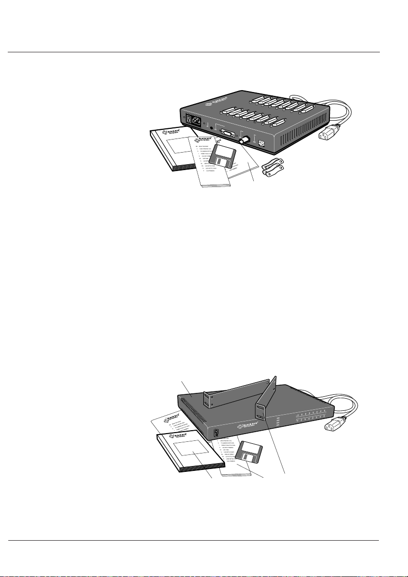
5 Packing list - Desktop Terminal Server. 11
6 Packing list - Rack Terminal Server 11
7 Packing list - 102/104 Terminal Server. 12
8 Connections Menu. 17
9 Commands pop-up menu. 18
10 Administration Menu (view level). 18
11 Administration Menu (password level). 19
12 Server Configuration menu. 20
13 Commands pop-up menu (server confign). 21
14 Port Setup Menu screen. 22
15 Port Setup Menu screen. 28
16 Host Address Menu Screen. 29
17 Connections Menu - Commands pop-up menu. 30
18 Port Setup Menu for PPP connections. 33
19 Remote Site Devices Screen. 36
20 Host Authentication and Logging screen. 40
21 Example log file. 45
22 Port Setup Menu screen. 47
23 Gateway Menu screen. 49
24 Remote Access Systems Screen menu. 50
25 Remote Site Devices Screen. 52
26 Ioland printing - Port Setup Menu screen. 55
27 LPD printing - Port Setup Menu screen. 57
28 RCP printing - Port Setup Menu screen. 63
29 Reverse Telnet - Port Setup Menu screen. 70
30 Commands - Exit pop-up menu. 77
31 Connections Menu - Commands pop-up menu. 79
32 Port Setup Menu. 81
33 Administration Menu. 91
34 Administration Menu (password level). 92
35 Access menu for Remote System Access. 93
36 Remote Access Systems Screen. 93
37 Remote Site Devices Screen. 95
38 Host Authentication And Logging menu. 96
v
Page 8

Terminal Server
- User and Administration Guide
39 Administration - Gateway Menu. 99
40 Administration - Host Address Menu. 100
41 Administration Menu - LInes pop-up menu. 101
42 Lines - Access Menu. 101
43 Lines - Flow Control Menu. 102
44 Lines - Hardware Menu. 102
45 Lines - Network Connection Menu. 102
46 Lines - Options Menu. 103
47 Lines - Terminal Menu. 103
48 Server Configuration menu. 104
49 Server Statistics pop-up menu. 107
50 SNMP Trap Configuration Menu. 107
51 Server Statistics pop-up menu. 126
52 Server Statistics screen - users. 127
53 Server Statistics screen - framed link status. 127
54 Network Connection Status screen. 128
55 Gateway Tables screen. 128
56 Server Statistics screen - port activity. 129
57 Server Statistics screen - line status. 129
58 Desktop Terminal Server DB-25 connector. 132
59 Desktop Terminal Server DB25 RS-232 pinouts (DTE). 132
60 Terminal Server RJ-45 connector. 133
61 Rack and 102/104 Terminal Servers RJ45
RS-232 pinouts (DTE). 133
62 Terminal Server RJ-45 connector. 134
63 Rack and 102/104 Terminal Servers RJ45
RS-422 pinouts (DTE). 134
64 Desktop Terminal Server Standard modem cables. 135
65 Rack and 102/104 Terminal Servers
Standard modem cables. 135
66 Desktop Terminal Server Standard terminal/PC cables. 136
67 Desktop Terminal Server PC cables. 136
68 Rack and 102/104 Terminal Servers
Standard terminal/PC cables. 136
69 Rack and 102/104 Terminal Servers PC cables. 136
70 Desktop Terminal Server cables
with Hardware Flow Control. 137
71 Rack and 102/104 Terminal Servers cables
with Hardware Flow Control. 137
vi
Page 9

Introduction 1
Thank you for purchasing a BLACK BOX® Terminal Server.
The Terminal Server is a unique Ethernet TCP/IP
communications server allowing serial devices to be
connected directly to LANs and WANS. The 2, 4, 8 or 16
serial ports enable the Terminal Server to connect to a wide
range of devices including:
Modems for remote access and Internet access
•
• ISDN adapters for branch remote access
and Internet access
• Terminals for multi-user Unix systems
• PCs using terminal emulation or SLIP/PPP
• All types of serial printers
• Data acquisition equipment (manufacturing,
laboratory, etc.)
• Retail point-of-sale equipment (bar coding,
registers, etc.)
The performance and flexibility of the BLACK BOX
Terminal Server allows you to use a wide range of high
speed devices in complex application environments. These
operating systems include:
Introduction
®
®
• Windows
• Windows NT
• Citrix Winframe
• SCO Unix & Gemini
• IBM AIX
• Sunsoft Solaris
• Hewlett Packard HP-UX
• Data General DG/UX
•
All other variants of Unix (BSD, Linux, IRIX, etc.)
95/98
®
1
Page 10
Terminal Server
- User and Administration Guide
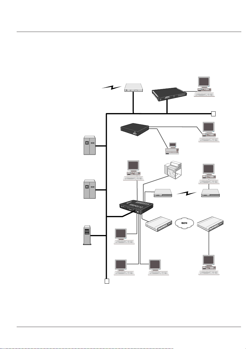
This configuration diagram shows many of the features
available on the Terminal Servers:
The
Internet
SCO Unix
Server
AIX
Server
Windows NT
Server
Terminal Server
104
POW
ER
102/104
Terminal
Server
Local PC
Desktop
Terminal
Server
9
0
-2
0
0V A
C
50-6
0
H
z 2
am
p
fu
se
POWER
Terminal
Router
NE
T
1
2
3
4
er
rv
e
al S
in
erm
T
AUI
IO
Rack
Terminal Server
x
T
12345678
POWER
AUI
Rx
10BASE2
10BASE-T
ER
POW
Cash
Register
Local PC
Local PC
Printer
Remote PC
Modem
Modem
B
AS
E2
IOBASE-T
ISDN TA
ISDN TA
Terminal
Terminal
Remote PC
Figure 1: Terminal Server features and applications
2
Page 11

Introduction
1.1 About this
Guide
This guide describes the features and applications of the
Terminal Server from the level of novice user to more
experienced system installer. It includes information about
the table top units as well as the rack mount unit (form factor
is the only difference between them).
As an experienced user, you may save yourself some set-up time
by following the instructions in the Terminal Server Quick Start
Guide included with your package. Consult other sections in
this guide as required. Release notes are also available with this
unit (enclosed, or available from our web sites).
Note: The
BLACK BOX® Terminal Server
supports Windows
®
systems including Windows NT® , Windows® 95/98 and
®
Windows
features not included with Windows
3.x. When compared to Unix, there are several key
®
systems such as TFTP,
dial-out socket connections, etc. However, we have provided
a briefing on these in the applicable sections. In many cases,
we will point you to our FTP sites for the latest tips and
®
software for the Terminal Server and Windows
systems.
This guide is sectioned as follows:
Installing your Terminal Server
Terminals on Multi-user Systems
Setting up Dial-in Modem Ports
Modem Authentication & Logging
Setting up Dial-out Modem Ports
Printing
- Using ioland
- Using LPD
- Using RCP
3
Page 12

Terminal Server
- User and Administration Guide
Other Devices Setup
The Menu Interface
Command Line Interface (CLI)
Troubleshooting & Maintenance
Cabling Guide
Technical Specification
Notation
The following notations are used to describe commands:
Conventions Used
Description Meaning
<parameter description>
[parameter description]
|
Text in the following font:
indicates input to, or output from the Terminal Server.
Screens illustrated in this guide may differ from those actually
viewed. However, information contained is valid for both
Unix and Windows
set term ansi
®
systems, and Terminals.
mandatory parameter
optional parameter
option separator
4
Page 13

Introduction
1.2 On-line
Documentation
1.3 Getting
Support
1.4 Terminal
Server
This guide cannot cover all the information available to you
about the latest developments and new features. However,
there are a series of on-line documents available to help you to
use the Terminal Server. You can check the support sections
of our web sites for the latest information:
•
www.blackbox.com
•
www.blackbox.co.uk
If you encounter problems during setup or general
maintenance, contact
standard support route for the quickest answers:
For technical support
1. Have your serial number and problem overview ready
then…
2. Tel: 724 746 5500 and / or
Fax: 724 746 0746 and / or
Email: support@blackbox.com
BLACK BOX® for support. Here is the
,
Features
The Terminal Server is a TCP/IP server with (depending on the
version) 2, 4, 8 or 16, RS-232 or RS-422 ports for making serial
network connections. It attaches to your TCP/IP network and
allows serial devices such as modems, terminals and printers to
access the network.
5
Page 14

Terminal Server
- User and Administration Guide
The Terminal Server hardware features:
• 2, 4, 8 or 16 serial lines, fully configurable with port
speeds of up to 115.2 kbps.
• RJ45 on Rack and 102/104 Terminal Servers or
DB25 RS-232 connectors on Desktop version.
• Full modem control using DTR, DSR, CTS, RTS
and DCD.
• FLASH memory for downloading firmware releases.
• The 102/104 Terminal Server has 10BASE-T
interface whilst the Rack and Desktop Terminal
Servers have auto sensing 10BASE2, 10BASE-T and
AUI Ethernet interfaces.
• Auto sensing power supply; 110-250V AC (48-60V
DC option available on Rack version).
• LEDs for diagnostic testing.
• Self-test on power-up.
• Rack mount or tabletop design.
The Terminal Server software features include:
• Support for TCP/IP protocols including telnet
and rlogin.
• Remote access support including PPP, SLIP
and CSLIP.
•
Printer support via lpd, rcp, and ioland utilities.
• Modem support via PPP and other utilities.
• Utilities provide ‘fixed tty’ support for
Unix systems.
• A window oriented menu interface with pop-up
menus and on screen help (command line
also available).
6
Page 15

• ARP or BOOTP for network based setup.
Terminal Server
102/104
Desktop
Rack
Type
Table Top
Table Top
Rack Mount
No. Ports
2, 4
8, 16
8, 16
Connector
RJ45
DB25
RJ45
RS-232
RS-232
RS-232
RS-422
Interface
• Dynamic statistics displays and line status
reporting for fast problem diagnosis.
• Multiscreens on terminals.
• Full support of SNMP MIBs, allowing
remote configuration via SNMP as well as
statistics gathering.
• Interoperability with IP routing through
gateway tables.
• Domain Name Server support.
• WINS support for Windows
®
environments.
• Port configuration copy and save functions.
The Terminal Server security features include:
• Supervisory and port password.
• Port locking.
Introduction
Hardware
Description
• Authentication with PAP support.
• Per user access level assignment.
• Service logging.
• Logging facility for audit and billing.
• Modem auto reset.
The following table and diagrams describe the units:
7
Page 16
Terminal Server
- User and Administration Guide
Serial Ports
90-200V AC 50-60Hz 2amp fuse
AUIPOWER
IOBASE2 IOBASE-T
123456 78910
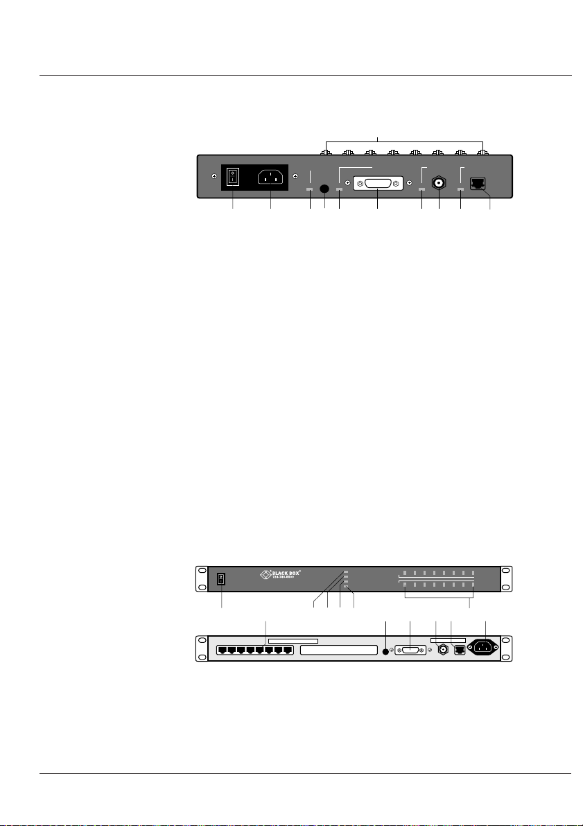
Figure 2: Hardware description - Desktop Terminal Server.
1 Main power switch
2 Power input socket
3 Power indicator
4 Reset switch cover
5 AUI indicator
6 AUI connector
7 10BASE2 indicator
8 10BASE2 connector (universal)
9 10BASE-T indicator
10 10BASE-T connector
11 Port activity indicators (Rack only)
POWER
Rack Terminal Server
Serial Ports
12345678
POWER
AUI
10BASE2
10BASE-T
Tx
12345678
Rx
3579 4 6 8101121
AUI IOBASE2 IOBASE-T 110-230V AC 50-60Hz
Figure 3: Hardware description - Rack Terminal Server.
8
Page 17
Introduction
RS-232/RS422
Terminal Server
POWER NET 1 2
1Serial Ports 2 3 4 5 6
724-746-5503
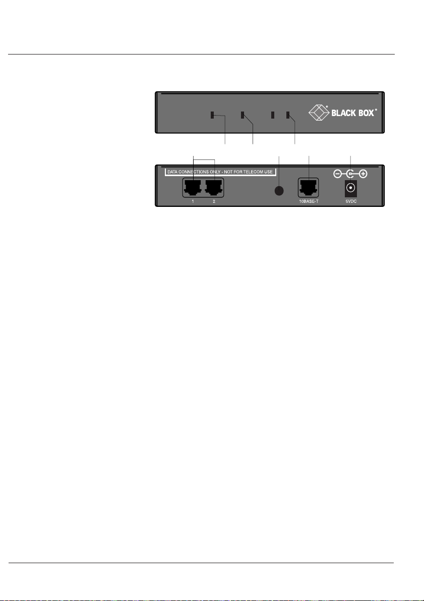
Figure 4: Hardware description - 102/104 Terminal Server
1 Power Indicator
2 Network indicator
3 Reset switch cover
4 Port activity indicators
5 10BASE-T socket
6 Power input socket
Functionally, the difference between RS-232 and RS-422
versions is the absence of support for hardware flow control
lines (RTS and CTS) and modem control lines (DSR, DTR and
DCD) in the RS-422 version. The performance and support
for 115.2k baud are unaffected by the different serial ports.
Software
description
RS-422 uses differential signalling and is capable of handling
longer distance due to superior noise immunity when
installed with suitable cabling.
The Terminal Server comes with the Software Support Disk.
This disk contains the latest ‘released’ firmware and the
redirector software for Unix systems called
firmware is a backup copy and generally not used. The
ioland
software is used for setting up printers and dial-out
modems on Unix.
ioland
. The
9
Page 18

Terminal Server
- User and Administration Guide
The Terminal Server uses TFTP for downloading new
tftpd
firmware.
AIX and HP-UX but disabled by default.
Consult your Unix manual on this subject. On Windows
tftpd
is not provided at this time (see our
shareware
Note: Beta copies of the ‘next’ firmware release are usually
available on web sites (consult README files before
downloading).
Regarding
source code
binaries of
SCO, AIX, HP-UX, Solaris, etc.). The source code can be
compiled on any Unix system (consult your Unix manual
on this subject).
Note: The most recent versions of these binaries should be
available on web sites.
is included with Unix systems such as SCO,
tftpd
program).
ioland
, for printers/modems on Unix systems, the
ioland.c
ioland
is provided. There are also several
ready to run for various Unix systems (i.e.
FTP
site for a
®
,
1.5 Packing Lists
Desktop Terminal
Server
10
The following are check lists of the contents of your
package:
1Terminal Server
2This handbook
3Suppport Software Disk and Quick Start Guide
4Electrical Safety Booklet
54 wall mount brackets
6Power cable
Page 19
Introduction
Rack Terminal
Server
1
2
90-200V AC 50-60Hz 2amp fuse
3
erver
inal S
erm
T
POWER
AUI
IOBASE2
IOBASE-T
4
5
Figure 5: Packing list - Desktop Terminal Server
1Terminal Server
2Electrical Safety Booklet
3This handbook
4Suppport Software Disk and Quick Start Guide
52 rack mount brackets
6Power cable
6
1
2
POWER
Rack Terminal Server
3
4
Tx
12345678
POWER
AUI
Rx
10BASE2
10BASE-T
5
Figure 6: Packing list - Rack Terminal Server
6
11
Page 20
Terminal Server
- User and Administration Guide
102/104 Terminal
Server
2
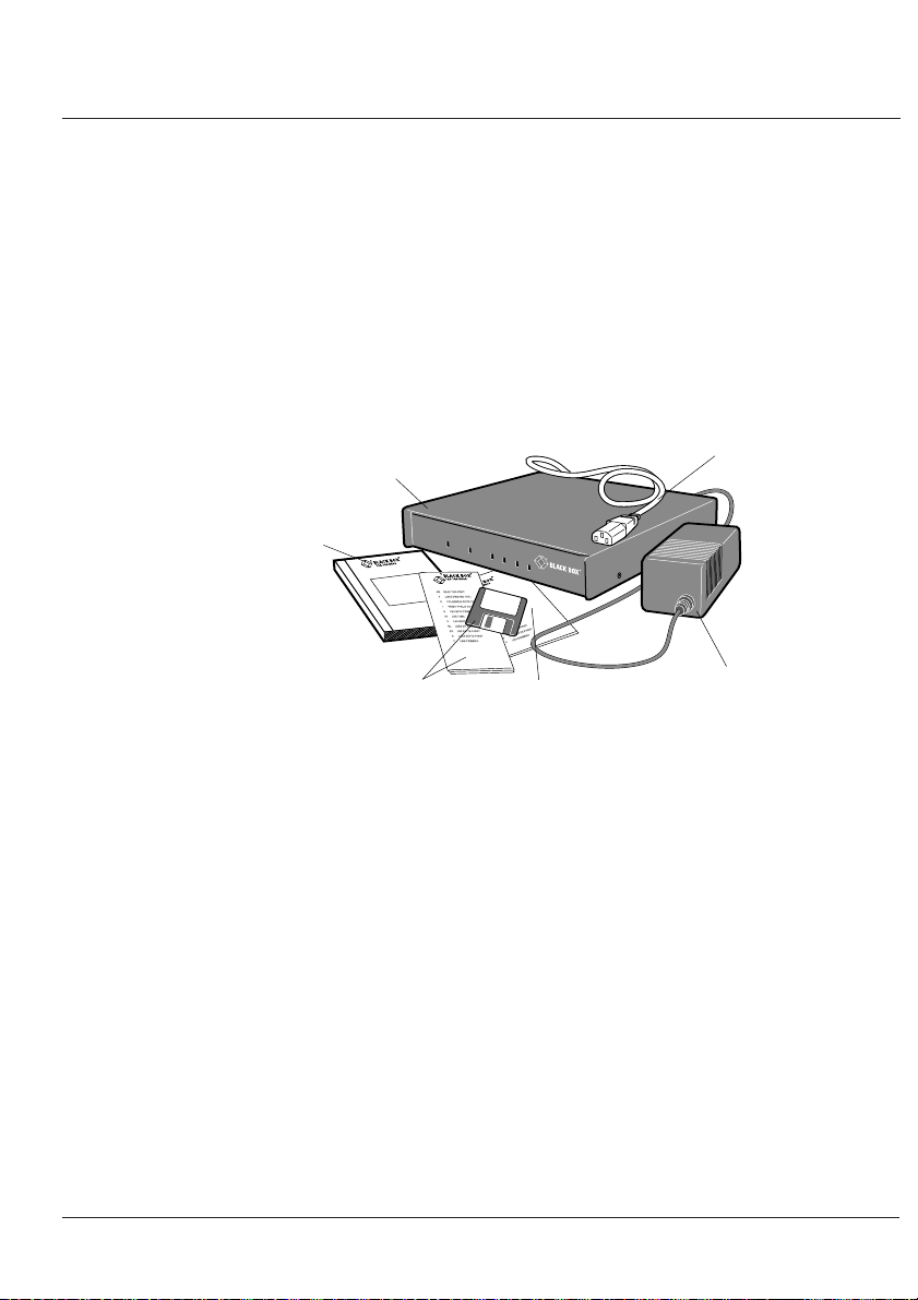
Figure 7: Packing list - 102/104 Terminal Server.
1 102/104 Terminal Server
2 This handbook
3 Support software disk and Quick Start Guide
4 Electrical Safety Booklet
5 Power supply unit
6 Power cable
1
Terminal Server
POWER
NE
T
1
2
3
724-746-5503
4
3
4
5
5
12
Page 21

Installing your IOLAN+
Installation 2
Below is a step-by-step guide on how to configure the
Terminal Server. You can also reference the
Quick Start Guide
First connect the Terminal Server to a network then begin
configuring the unit for your application. Additional
information on configuring modems and printers follows.
.
Terminal Server
2.1 Connecting
to your
Network
10BASE-T
(twisted pair)
10BASE2
(Thin Ethernet)
AUI port
2.2 Switching on
the Terminal
Server
The Desktop and Rack Terminal Servers connect to your
Ethernet network via one of the three auto sensing ports:
10BASE-T (twisted pair), 10BASE2 (thin) or AUI. The 102/
104 Terminal Server has 10BASE-T only. The Desktop and
Rack version default is 10BASE2.
Attach the RJ connector from a hub directly to the Terminal
Server's twisted pair port.
Attach a BNC T connector directly to the Terminal Server. If
your Terminal Server is the termination point for the cable
you need to add a terminator. Always ensure that each
segment of the thin Ethernet cable is at least 0.5m in length.
The maximum length for a thin Ethernet cable is 185 metres.
The AUI connector allows an external transceiver to be
connected. This allows a number of different interfaces to
connect including 10BASE5 (or thick) and fibre optic transceivers.
The Terminal Server power supply accepts input voltages in
the range 110 to 240V AC, allowing it to be used world-wide.
The102/104 server has an external power supply unit.
After you connect your LAN interface, you can power up the
unit. The green power indicator at the side (or front for Rack
and 102/104 units) should be lit. If the unit fails to power up
with the green power indicator lit, disconnect the unit and
contact Black Box.
13
Page 22

Terminal Server
2.3
Communicating
via ARP
- User and Administration Guide
The green Ethernet indicators show the active connections. It
remains lit and will blink when LAN traffic is active.
Note: To change your Ethernet media, you will need to
reboot the unit to activate the connector.
You are now ready to begin communicating with your
Terminal Server. You can connect to the Terminal Server in
different ways: via a terminal or PC on port 1, or using ARP
or BOOTP. Using ARP is the preferred method for both
Windows
port 1 is often used. BOOTP setup is for Unix users only and
is included in the
method for your application. Third party BOOTP packages
are available for Windows
The Terminal Server supports the ‘Address Resolution
Protocol’ (ARP). It allows you to temporarily connect to your
Terminal Server to assign a permanent IP address. If you
prefer to use a terminal or PC attached to the Terminal
Server, skip to the next section.
®
and Unix, however a terminal or PC attached to
Tips
section (2.6). Choose the appropriate
®
.
14
From a local Unix host, type the following:
arp -s a.b.c.d aa:bb:cc:dd:ee:ff
(Where a.b.c.d is the IP address you want for the Terminal
Server, and aa:bb:cc:dd:ee:ff is the Ethernet address of the
Terminal Server, found on the bottom of the unit itself.)
®
On a Windows
(using dashes instead of colons):
arp -s a.b.c.d aa-bb-cc-dd-ee-ff
Whether you use Unix or Windows® to run arp, you are now
ready to telnet to the Terminal Server.
system, the arp command is slightly different
Page 23

Installing your IOLAN+
Here is the sequence to use:
arp -s 192.168.209.8 00:80:D4:00:33:4e
telnet 192.168.209.8
password>
local>
At the password prompt, just hit since this is not set yet.
The IP address still needs to be configured on the unit (ARP
has only allowed you to connect to the unit so far).
Note: If there are any errors, recheck both the IP and
Ethernet addresses you keyed in (this is the most common
error here). See
(Appendix B)
You can now skip the next section and go straight to
The Menu System.
2.5,
Troubleshooting & Maintenance
for more information on problems.
section
2.4
Communicating
via a
Terminal or
PC
You can connect to the Terminal Server using a terminal or
PC (with a terminal emulation package such as Hyperterm).
Connect a terminal or your PC to port 1. The Terminal Server
serial ports are DTE type RS-232 ports. When connecting a
terminal/PC directly (without modems), the RS-232 signals
need to be crossed over (‘null modem’ cable). See the
Guide
(Appendix C) for pinout information.
For a terminal/PC to communicate with a server, set it to the
following: 9600 baud, eight data bits, one stop bit, software
flow control, no parity.
After powering up the Terminal Server, you are prompted to
enter a ‘Local login:>‘. You can just hit any character and
at this point (the character is required).
Cabling
15
Page 24

Terminal Server
- User and Administration Guide
2.5 The Menu
System
The next prompt displayed is
Line Interface (CLI) prompt.
Note:
If there are any problems, check the cable you are
using (this is the most common error). Port 1 is configured to
provide error messages should any problems occur.
Troubleshooting
information on problems.
You can now move to
You should now be at the Command Line Interface (CLI) of
the Terminal Server as designated by the
you would like to continue in CLI mode refer to
but we recommend the menu system.
Set the terminal emulation type and begin using the menus.
The following are the terminal options:
ansi, dumb, vt100, wyse50, wyse60, tvi925,
ibm3151, vt320, falco50, hp700
The default setting is ‘dumb’. To set the menu interface to
your emulation simply type
Example:
&
Maintenance
local>
, which is the Command
(Appendix B) for more
The Menu System.
set term
with your option.
local>
prompt. If
See
Appendix A
,
16
local> set term ansi
To switch from the command line interface to the menu
local>
interface, at the
set menu
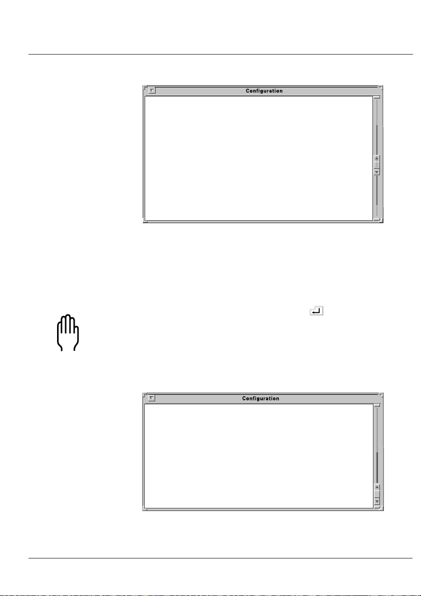
The
Connections Menu
This menu displays the current state of the four possible
connections. There are no active connections.
prompt enter:
should now be displayed.
Page 25

Installing your IOLAN+
CONNECTIONS MENU REMOTE-ADMIN
Connection Host
1 *** FREE ***
2 *** FREE ***
3 *** FREE ***
4 *** FREE ***
________________________________________________________________________________
v4.02 a CDi TERMINAL SERVER
Figure 8: Connections Menu.
The firmware version of the Terminal Server is located on the
lower left hand portion (in this example, version 4.02). The
wording ‘REMOTE-ADMIN’ in the upper right signifies you
are remotely telneted into the server (and will read
‘Terminal: 1’ if you are using a terminal/PC into port 1.)
Connections
Menu
The keys used to move about in the menus depend on the
terminal emulation you are using. The arrow keys should all
work. The TAB key is very important for moving between fields.
Backspace and DEL should work, but depend on the emulation.
ESC (the escape key) will move you back one menu.
Note: If there is a problem with your emulation, you can try
a different emulation mode. See
Maintenance
(Appendix B) for more information.
Troubleshooting
&
An accelerator key can be used to jump to an option within
a menu and is the first letter of the option.
Select connection '1’ on the
the
key. The
Commands
Connections Menu
and press
pop-up menu is displayed.
There are a number of options available from this menu.
17
Page 26
Terminal Server
- User and Administration Guide
Connection Host
1 *** FREE ** === Commands ===
2 *** FREE ** | Telnet ^T|
3 *** FREE ** | Rlogin ^R|
4 *** FREE ** | Port ^P|
| Admin mode ^A|
| CLI |
| Lock |
| Logout ^D|
================
________________________________________________________________________________
This option allows you to configure parameters affecting
RACK v4.02 a CDi TERMINAL SERVER
the Server box, eg hosts table, other terminals.
Figure 9: Commands pop-up menu.
Before communication across the network can be established
the Terminal Server must be assigned a network IP address.
This is accessed through the
Administration Menu
.
Administration
Menu
18
Select the
Admin mode
Note: If you are telneted into the server, the
port
options do not appear on the
The top level
ADMINISTRATION MENU REMOTE-ADMIN
gateway Examine/modify gateway table.
host Examine/modify host table.
line Terminal configuration organised by line.
password Specify password to allow modification of menu items.
port Terminal configuration organised by port.
quit Return to connections menu.
server Examine/modify Server parameters.
stats Examine Server statistics.
________________________________________________________________________________
Administration Menu
field and press the key.
telnet, rlogin
Commands
pop-up menu.
appears as follows:
and
Figure 10: Administration Menu (view level).
Page 27

Installing your IOLAN+
Select the
factory default password here: this is
Password
field and press the key. Use the
iolan
(no caps).
Note: This password level will time-out in four minutes if
there is no activity. This is for security reasons and will take
you back to
The
Administration Menu
some extra fields
** Administrator ** ADMINISTRATION MENU REMOTE-ADMIN
access Remote System Access (PPP).
change Change login and/or admin password.
gateway Examine/modify gateway table.
host Examine/modify host table.
kill Kill TCP connections on serial line.
line Terminal configuration organised by line.
port Terminal configuration organised by port.
quit Return to connections menu.
reboot Reboot Server.
server Examine/modify Server parameters.
stats Examine Server statistics.
trap Examine/modify SNMP Trap parameters.
________________________________________________________________________________
Administration Menu
is redisplayed, however it now has
(access, change, kill, reboot, trap
(view level).
).
Figure 11: Administration Menu (password level).
Select the
into the
server
entry and press the key. This takes you
Server Configuration Menu
.
Server
Configuration
Menu
There are a number of fields in the
which are explained in Section 9,
menu
At this point, you just need to give the Terminal Server an
and a
name
address
.
Server Configuration
The Menu Interface
IP
19
.
Page 28

Terminal Server
- User and Administration Guide
** Administrator ** SERVER CONFIGURATION REMOTE-ADMIN
Name [TSERVER ] Debug mode [0 ]
IP address [204.17.209.8 ]
Subnet mask [ ]
Ethernet address [00:80:d4:00:9e:a1] Ethernet interface [AUTO ]
Language [English ]
Identification [ ]
Lock [Disabled]
Password limit [5 ]
CR to initiate [Yes ]
SNAP encoding [Disabled]
Boot host [204.17.209.1 ] Boot diagnostics [Enabled ]
Boot file [ ]
Init file [ ]
MOTD file [ ]
Domain name [ ]
Name server [ ] NS Port [53 ]
WINS server [ ]
________________________________________________________________________________
Figure 12: Server Configuration menu.
The important fields that you need to fill in are as follows:
Name: In the example above the terminal server name
has been set to
Terminal Server name entered here to match the
name entered in the host machine’s domain
name server.
TSERVER
It is a good idea for the
20
Note: For more information about domain name servers,
consult your operating system manuals.
IP Address: This address must be set to a value that is
consistent with the network the server is on.
Having filled in the fields press the key. This brings the
Commands
Note:
pop-up menu as shown below.
The Ethernet address is factory set. This address is
uniquely assigned to the Terminal Server and MUST NOT
be changed
.
Page 29

Installing your IOLAN+
Subnet mask [ ]
Ethernet address [00:80:d4:00:9e: == Commands ===ernet interface [AUTO ]
Language [English ] | Save & Exit |
Identification [ | Quit & Exit | ]
Lock [Disabled] | Values |
Password limit [5 ] | Cancel |
CR to initiate [Yes ] ===============
SNAP encoding [Disabled]
Figure 13: Commands pop-up menu (server confign).
Port Setup Menu
and Beyond
Select the
options are
before exiting this menu,
optional values for this field if available, and
Save & Exit
Quit & Exit,
field and press the key. Other
which does not save the changes
Values,
which will display the
Cancel,
which
will take you back to this screen for more editing.
You have now set up the unit with a new IP address. This
should be confirmed with the message:
IP CHANGED—PLEASE REBOOT
Reboot the Terminal Server to activate the new IP address
reboot
using the
command. The IP address and/or subnet
mask are the only parameters that when changed necessitate
rebooting.
Your terminal server is now ready to configure for terminals
on multi-user systems or modems, printers and other devices.
The next sections deal with each of these. If you’ve got a
good feel for the menu system, you should proceed to the
section appropriate for your application.
If you’d like a full review of the menu system refer to Section
The Menu Interface
9,
later in this guide. For more
information about the Command Line mode, consult
Command Line Interface
(Appendix A)
.
21
Page 30

Terminal Server
- User and Administration Guide
All of the procedures are based around the
This is accessed through the
Administration Menu
Port Setup Menu
(password
.
level). Remember, that if you are not in the password level,
you can only view the information, not change it.
Here is the
** Administrator ** PORT SETUP MENU REMOTE-ADMIN
Hardware Flow ctrl Keys
Speed [9600 ] Flow ctrl [XON/XOFF] Hot [^]] Intr [^C]
Parity [None] Input Flow [Enabled ] Quit [^@] Kill [^U]
Bit [8] Output Flow [Enabled ] Del [^@] Sess [^@]
Stop [1 ] Echo [^@]
Break [Disabled] IP Addresses
Monitor DSR [No ] Src [ ] Mask [ ]
Monitor DCD [No ] Dst [ ]
User Options Access
Name [ ] Keepalive [No ] Access [Local ]
Terminal type [ansi ] Rlogin/Telnet [Telnet] Authentication [None ]
TERM [ ] Debug options [No ] Mode [Raw ]
Video pages [0] Map CR to CR LF [No ] Connection [None ]
CLI/Menu [Menu] Hex data [No ] Host [ ]
Reset Term [No ] Secure [No ] Remote Port [0 ]
MOTD [No ] Local Port [10006]
________________________________________________________________________________
Port Setup Menu
:
Figure 14: Port Setup Menu screen.
This menu allows the user to set up all the parameters
associated with a port. The administrator can alter the set-up
of any port on the terminal server while a user can only alter
the set-up for their own port.
22
This menu is divided into the following sections:
Hardware:
Defines port type and is used for setting up the
hardware configuration of the modem, terminal,
printer or PC session. This section is always used.
User:
Defines various user parameters such as name and
terminal type. Most fields are used in this section.
Flow Control:
Defines the various flow control options used by
the Terminal Server. This section is always used.
Page 31

2.6 Tips
Installing your IOLAN+
IP Addresses: Deals with remote access via PPP/SLIP sessions.
Options: Deals mainly with the telnet options. This
section is the least used.
Keys: Defines the various accelerator keys that the
server responds to and can be used for
convenience.
Access: Controls the type of the connection made from
this port. This is the most important section in
defining a port.
If you’re ready to install terminals, printers and modems,
proceed to the appropriate section. For a good review, go to
Section 9,
The Menu System.
Copy Command
Connecting via
BOOTP (for Unix
systems only)
The Terminal Server has a copy command that allows you to
copy the setup of one port to another. You will need to get to the
CLI (from the
Note: To get back to the menu system once in the CLI, type
set menu
The command above would copy the configuration of port number
1 to ports 2, 3, 4 and 5 (and return you to the menu system).
The Terminal Server supports BOOTP which allows the
server to dynamically configure itself on startup. Upon
startup the Terminal Server sends four BOOTP broadcast
requests if it has no IP address. This broadcast request
packet contains the Ethernet address of your unit.
Connection
at the command line.
tserver> su
password>
ADMIN:local> copy 1 2 3 4 5
ADMIN:local> set menu
menu) and use the following syntax.
23
Page 32

Terminal Server
- User and Administration Guide
The request is received by all hosts on the network and is
checked against a file to find a match. This data base file will
normally be
Where:
ht
is the type of network
ha
is the Ethernet address on back of the Terminal Server
hd is the home directory for specifying the server firmware (optional)
bf
is the name of the Terminal Server firmware (optional)
ip
is the IP address you want to use
Note: This BOOTP implementation is a subset and not a full
implementation of the RFC.
Note: The most common error is bad information in the
/etc/bootptab
Maintenance
/etc/bootptab
# bootptab description
:ht=ethernet:ha=0080d400024e:\
:hd=tftp:\
:bf=tserver.DL:\
:ip=192.168.209.8:
file (recheck it). See
(Appendix B) for more information.
and will be of the following format:
Troubleshooting &
Saving and
Downloading
Configurations
24
You can now move back to
It is possible to save the configuration of your Terminal Server.
This is convenient for loading multiple terminal servers with
the same setup. It is also advisable as a backup method.
If the boot file name has the extension ' .cfg ' (eg
will be loaded as a configuration file rather than a boot file.
This allows the administrator to configure one Terminal Server
unit, save its configuration and automatically configure
subsequent units via bootp.
Should the configuration of your Terminal Server ever be
corrupted because of user error or damage, keep a copy of
the configuration stored somewhere for easy re-installation.
The Menu System
in this chapter.
tserver.cfg
), it
Page 33

Installing your IOLAN+
This can be achieved by uploading the configuration of the
unit to a host on the network. To do this, enter the
Communications Server Menu
Select the
Menu.
Set this to the full pathname of the file in which you wish to
store the configuration. Set
you wish the file to reside within and save these entries.
Boot host: rockvegas (or ip address)
Init file: /tftp/term_serv.cfg
Log onto the host machine in the normal manner and create
the file you have specified in the Terminal Server menu, this
could be as shown below:
touch term_serv.cfg
Note: This file must exist with the correct read/write
permissions before you write to it.
Init file
from the
entry of this menu.
Boot host
Administration
to the host machine
This can be accomplished by hitting
option in the pop up menu at the
as the administrator, by typing:
su
Enter the password and type:
save config
This uploads the terminal server port configurations to the host
in a format that can be downloaded at a later date.
Note: This does not save any of the settings configured in
the
Communications Server Menu
language, name, subnet mask, etc.
The Terminal Server will now automatically download this
configuration on reboot. Remember that whenever you
change a setting on the unit, it will be overwritten the next
time the unit is rebooted unless the new configuration is saved.
and selecting the
local>
prompt. Use the
, including the IP address,
CLI
CLI
25
Page 34

Terminal Server
- User and Administration Guide
Domain Name
Server (DNS)
Reassigning the
Server to a
New Network
The Terminal Server can be configured to take advantage of
your network’s Domain Name Server (DNS). This is done
from the
your DNS in the
field as well.
If you need to attach the Terminal Server to a different
network with a new IP address, it is possible to reset it to
factory default condition using the following procedure:
After this is done, the unit will start sending BOOTP request
packets.
This procedure is useful for factory defaulting units which
cannot be reached via TCP/IP. This includes reassigning a
programmed unit to a network to which the previously
assigned IP address does not belong.
Administration Menu
name server
1 Power on the unit
2 Wait 30 seconds
3 Hold down the RESET button for 15 seconds
4 Release the button
by keying in the IP address of
field. Fill in the
domain name
Updating
Terminal Server
Firmware
26
Firmware can be downloaded across the network using tftp
protocol if the host machine and file name are set in the
and
host
are checked at start up and if they have been configured, the
relevant file will be downloaded.
Note: tftp must be enabled on the releveant host as it is
disabled by default.
boot file
entries of the server menu. These entries
boot
Page 35

Terminals on Multi-user Systems 3
The Terminal Server is used extensively for connecting
terminals, printers and modems on multi-user Unix systems,
especially in retail applications. These Unix systems include
SCO Unix, IBM AIX, HP-UX, Data General’s DG/UX, etc.
This section deals with terminals and/or PCs using emulation
packages (such as Hyperterm). For information on adding
printers, modems or other devices, please refer to the
respective sections.
Terminals on Multi-user Systems
3.1 Terminal Port
Configuration
Installation
The
with access to the menu system. This is convenient for most
users. But in many applications, the users need to be ‘direct
connected’ to a specific Unix host so that they see the
prompt automatically. This is helpful in securing your
system, or in environments where the users need to be in
one application only.
This section will show how to setup a terminal, and other
tips such as the concept of ‘fixed ttys’, multiscreens, the
copy command, TERM features, etc. Consult Appendix C,
Cabling Guide,
Remember to use the TAB key to bounce between fields,
and if you get the
hitting
This is the setup for making a terminal connect to a
designated Unix host
The
Port Setup Menu
section covered how to attach a terminal
for information on wiring your terminal.
, use
Commands
Cancel
login
screen is shown overleaf.
exit menu by mistake by
to return to editing this menu.
prompt automatically.
login
27
Page 36

Terminal Server
- User and Administration Guide
** Administrator ** PORT SETUP MENU REMOTE-ADMIN
Hardware Flow ctrl Keys
Speed [9600 ] Flow ctrl [XON/XOFF] Hot [^]] Intr [^C]
Parity [None] Input Flow [Enabled ] Quit [^@] Kill [^U]
Bit [8] Output Flow [Enabled ] Del [^@] Sess [^@]
Stop [1 ] Echo [^@]
Break [Disabled] IP Addresses
Monitor DSR [No ] Src [ ] Mask [ ]
Monitor DCD [No ] Dst [ ]
User Options Access
Name [ ] Keepalive [No ] Access [Local ]
Terminal type [ansi ] Rlogin/Telnet [Telnet] Authentication [None ]
TERM [ ] Debug options [No ] Mode [Telnet]
Video pages [0] Map CR to CR LF [No ] Connection [Initiated]
CLI/Menu [Menu] Hex data [No ] Host [204.17.209.1 ]
Reset Term [No ] Secure [No ] Remote Port [23 ]
MOTD [No ] Local Port [10006]
________________________________________________________________________________
Figure 15: Port Setup Menu screen.
The following fields are important:
28
Access: Set this field to
Local
. This tells the Terminal
Server port to listen for data on the RS-232 side.
Mode: With this field set to
in telnet mode (or
telnet
, the port will operate
raw
for rlogin). Most systems
will use telnet.
Connection:
Set this field to
Initiated
and the port will establish
a TCP/IP connection to a specified host only after
receiving a <CR> on the RS-232 port. If you set this
field to
none
, then the user of this port will see the
menu system when the terminal is powered on.
Host:
Use this field to define which host computer you
want the port to automatically connect to when
using
Initiated
address or if you setup the
connections. Use the host’s IP
Host Address Menu
,
you can use a name (see next section).
Remote Port: This corresponds to Telnet service on the remote
host and must be set to the standard 23 (or 513
for rlogin).
Page 37

Terminals on Multi-user Systems
3.2 Host Table
Setup
Monitor DSR: You can set this field to
Yes
if you wire the
terminal’s DTR signal pin 20 (DB25) to the
Terminal Server's DSR signal pin 3 on the RJ45
conector (
see Cabling Guide
for DB25 pin
assignments). When you turn the terminal off, it
will reset the server port, which tells the Unix
host to kill the user’s processes.
In order for the Terminal Server to connect easily to
machines on the network it must know the IP addresses of
the other computers. The Terminal Server can have its own
internal table of IP addresses set up in the host table. This is
a ‘local’ naming system only. The Terminal Server can also
use the name server utility of your Unix system (consult your
Tips
Unix system manual and section 2-6,
The
Host Address Menu
by selecting the
Menu
is accessed from
host
entry. The host table can contain
).
the Administration
up to 10 addresses. Each entry consists of a host name and
its corresponding IP address.
** Administrator ** HOST ADDRESS MENU REMOTE-ADMIN
Entry Host name IP Address
1 [fred ] [204.17.209.70 ]
2 [astro ] [204.17.209.6 ]
3 [router ] [204.17.209.254 ]
4 [blackbox ] [204.17.209.1 ]
and so on…
________________________________________________________________________________
Figure 16: Host Address Menu Screen.
You can fill in an entry (both the name and the IP Address)
for your host machines and then save the values by pressing
key.
the
29
Page 38

Terminal Server
- User and Administration Guide
3.3 Making a
Connection
If you are using initiated connections, you will not see the
Terminal Server menus. Instead, you see the login prompt
of the host you assigned in the
. However, if your
Menu
Connections Menu
connection
appears. You are now ready to make
field of the
field is set to
Port Setup
None
, the
host
connections.
From the
*** FREE ***
the
Connections Menu
session to display the
Telnet
field and press the key.
Name: TSERVER CONNECTIONS MENU Terminal: 7
Connection Host
1 *** FREE ** === Commands ===
2 *** FREE ** | Telnet ^T|
3 *** FREE ** | Rlogin ^R|
4 *** FREE ** | Port ^P|
| Admin mode ^A|
| CLI |
| Lock |
| Logout ^D|
================
________________________________________________________________________________
press the key on a
Commands
menu. Select
30
Figure 17: Connections Menu - Commands pop-up menu.
This produces a pop-up menu allowing the choice of the
host machines that are configured in the host table. To select
a host, move the cursor down to the required name then
press the
key. At this point the unit attempts to make a
connection across the network to the indicated host using
the telnet protocol.
If it succeeds, the host machine’s login prompt is displayed.
There may be an error in the configuration if the connection
cannot be established.
Page 39

Terminals on Multi-user Systems
Note: At this point, check the host table again for correct
entries, then check the network connection and host
machine you’re connecting to.
While in session to the host machine, you can return to the
terminal server by using a hot key. This is user-defined, but
defaults to ^]. Press this key and the
displayed. To resume your connection select the host
session you were on (notice that the name of the host is now
displayed where
bring up the
Resume Connection
Note: If the ^] did not work, you might have a conflict with
that character sequence and should check the
of this port.
When logging out of your session the connection is
automatically closed.
*** FREE ***
Connection
option.
was). Press the key to
pop-up menu, then select the
Connections Menu
Keys
section
is
3.4 Tips
Connecting via
‘fixed ttys’
Multisessions on
terminals/PCs
The Terminal Server has the ability to create a ‘fixed tty’
under Unix. This is helpful for older or secure Unix
applications that require a fixed location for each terminal.
Consult section 8,
The Terminal Server is capable of supporting multiple
sessions. This allows the user to connect to all four
*** FREE ***
them using the ^] hot key. You can also key through the
screens by setting the session key (e.g. If set to ^A you would
bounce through the screens with a ^A1, ^A2, ^A3, ^A4.). If
you are using a terminal that supports video pages such as
the Wyse 60, the screens will be refreshed if you set the
video pages
supported by your terminal (for Wyse 60 = 3).
Other Devices Setup
sessions with different hosts and move between
field on the
Port Menu
.
to the number of pages
31
Page 40

Terminal Server
- User and Administration Guide
The TERM field
Gateway Tables
The
TERM
field in the
the terminal type information to the host. The
field is local to the Terminal Server but will be passed to the
host. The
to the host about the type of terminal. This allows you to
customise information being passed to the host. For
example, a user could encode the physical location into this
field (i.e. tty16) and then extract that at the host end to
determine which port the user has logged in on (i.e. port 16).
When the host and Terminal Server are connected via a
gateway router, a connection is not possible until the
gateway table has been updated with the IP address of the
local gateway machine. See section 9.7, the
section of
TERM
The Menu Interface
Port Setup Menu
field can override the information being sent
.
can be used to pass
terminal type
Gateway Menu
32
Page 41

Setting up Dial-in Modem Ports 4
Setting up Dial-in Modem Ports
This section will review the configuration necessary to create
dial-in connections. It will start with the most simple
connection such as a dial-in Unix connection. The section
then moves into setting up PPP ports which is how Windows
®
systems dial-in (as well as Unix). This is very important if you
are an Internet Service Provider (ISP) or a corporate site
providing remote access or Internet/Intranet access.
The Terminal Server can make a very good dial-in solution
for ISPs and corporate users alike by using its remote access
facilities. This section goes hand-in-hand with the next
section,
Modem Authentication and Logging
.
Note: In many of the modem examples, we are using PPP.
You can use SLIP and CSLIP in those applications requiring
these legacy modes.
4.1 Dial-in Port
Configuration
The following is the port configuration for a dial-in
connection, including PPP.
** Administrator ** PORT SETUP MENU REMOTE-ADMIN
Hardware Flow ctrl Keys
Speed [57600 ] Flow ctrl [Hardware] Hot [^@] Intr [^@]
Parity [None] Input Flow [Enabled ] Quit [^@] Kill [^@]
Bit [8] Output Flow [Enabled ] Del [^@] Sess [^@]
Stop [1 ] Echo [^@]
Break [Disabled] IP Addresses
Monitor DSR [No ] Src [ ] Mask [255.255.255.0 ]
Monitor DCD [Yes] Dst [204.17.209.101 ]
User Options Access
Name [ ] Keepalive [No ] Access [Local ]
Terminal type [ansi ] Rlogin/Telnet [Telnet] Authentication [Host ]
TERM [ ] Debug options [No ] Mode [Raw ]
Video pages [0] Map CR to CR LF [No ] Connection [Dedicated]
CLI/Menu [CLI ] Hex data [No ] Host [204.17.209.1 ]
Reset Term [No ] Secure [Yes ] Remote Port [513 ]
MOTD [No ] Local Port [10006]
________________________________________________________________________________
Figure 18: Port Setup Menu for PPP connections.
33
Page 42

Terminal Server
- User and Administration Guide
The following fields are important:
Monitor DCD:
TERM: This field is the TERM environment variable.
Flow Ctrl: The modem and terminal server port should be
Dst: This field contains the IP address the dial-in user
Mask: If using PPP, SLIP or CSLIP, this is the subnet
With this flag set to
monitor Data Carrier Detect (DCD) - pin 8 - from
the modem. As soon as your modem answers a
call and establishes a carrier signal, the modem
raises DCD. The terminal server will then
establish a telnet/rlogin connection to a specified
host. When the modem hangs up, DCD goes low
and the terminal server port resets. This will also
drop the connection to the host.
Whatever you type in here will be passed to the
host as the TERM variable when a telnet
connection is established and the user logs in.
configured to use Hardware (RTS/CTS) flow
control. This will be especially important if you
are using SLIP.
will borrow for the PPP session. If you are using
a straight forward dial-in connection for Unix,
this is not required.
mask that controls the range of IP addresses
accessible from the port and must correspond
with your network. (If used for terminals, this is
not needed.)
Yes
, the Terminal Server will
34
Secure: This field is set to
use the Dst IP address. (su is not available in this
mode.) If the Secure flag is set, the dial-in user
will not be able to obtain administrative
priveleges. This also applies to local terminals.
Yes
to force the call-in user to
Page 43

Setting up Dial-in Modem Ports
4.2 The Host
Access: Set this field to
the terminal server to listen for data on both the
RS-232 side and the network side. If only used
for dial-in, set to
the RS-232 side.
Connection:
Host:
Remote port: This corresponds to the Login (i.e. rlogin)
Local port: The
Make sure you have setup a valid user account for
authentication on the designated authentication host. See
Modem Authentication & Logging
With the connection set to
automatically connect to a specified host when not
doing PPP (DCD goes high on the modem).
When not doing PPP, this field defines which host
computer you want the port to automatically
connect to. Use the host’s IP address. You can
also define the host in the terminal server’s Host
Table and just use the name.
service on the remote host and must be 513 (or
23 for Telnet).
inetd
for this port is listening for TCP/IP connections
on TCP port 10006.
Dynamic
process running on the terminal server
. This sets the port of
Local
and it will only listen on
Dedicated
(section 5).
, the port will
4.3 The Modem
You will need to initialise the modem using a configuration
string. To do this, go to the
Access
(via the
the UNUSED ENTRY that corresponds to the port with the
modem attached (i.e. third one down is port 3, etc.). You
can set the type (i.e. name) and the
required configeration string (e.g.
are default.
section of the
Remote Site Devices
Administrative Menu
Modem Config
ate0s0=1&w
screen
). Select
to the
). All other fields
35
Page 44

Terminal Server
- User and Administration Guide
** Administrator ** REMOTE SITE DEVICES SCREEN REMOTE-ADMIN
Type [port3 ]
IP Addresses
Src Addr [ ]
Dst Addr [ ]
Modem
Config [ate0s0=1&w ]
Dial Comm [ ]
Hang Up [ ]
PPP Configuration Dialer Configuration
Restart timer [1 ] Dial Timeout [40]
Max Retries [5 ] Dial Retries [2 ]
Inactivity [0 ]
________________________________________________________________________________
Figure 19: Remote Site Devices Screen.
4.4 Client Login
36
You will now need to
or CLI) to activate the changes and configure the
Menu
kill
this port (from the
Administration
modem. The configuration string will be sent to the modem
after each call, keeping the modem in sync with the server.
When the caller connects, you may want to send out a
welcome message of some sort (see MOTD tip below). After
the user gets this message, you want him/her to enter a login
and password then connect to the Host for a shell account.
Or, if it is a PPP user, they will simply start sending PPP
®
packets at the login prompt (e.g. Windows
95/98) and use
PAP for authentication. Optionally, the dial-in user can
place a P, S or C (all caps) in front of the user name at the
Login prompt (this starts the corresponding protocol after
successful authentication).
Welcome to the Internet site
login: Cflint
password:
Host authentication succeeded.
Page 45

Setting up Dial-in Modem Ports
My IP Address is : 192.168.209.7
Your IP Address is : 192.168.209.210
The Subnet Mask is : 255.255.255.0
With this example, the Terminal Service is now in CSLIP mode,
so put your PC into CSLIP mode as well. Your dialer script will
have to parse out the My/Your addresses from the above
message. ‘Your IP Address’ will be the address of the PC that is
calling in, and ‘My IP Address’ can be the PC’s default gateway.
The above procedure works for SLIP and PPP as well.
However, PPP will not display the ‘My IP...’ message because
the IP addresses are negotiated automatically in the IPCP layer.
4.5 Tips
Domain Name
Server (DNS)
WINS Server
With the
Dedicated
user name, you will be authenticated and then connected to
the host. This will leave you at a shell prompt on the
Authentication host. A caller will never see the Terminal
Server. If
CLI prompt (i.e.
The Terminal Server can be configured to take advantage of
your network’s Domain Name Server (DNS). This is
important for ISPs. From the
server
server
If you have a local NT server running WINS and you want
dial-in clients to take advantage of that, put the IP address
of the NT server in the
Configuration
Note: The Windows
by setting 'Use DHCP for WINS resolution'.
Connection
, if you do not specify a P, S or C in front of the
Connection
and key in the IP address of your DNS in the
field. You could fill in the
local>
screen.
field on the
is set to
).
WINS server
®
95/98 client obtains the WINS address
Port Setup Menu
None
, you will be left at the
Administration Menu
Domain name
field of the
field as well.
Server
set to
select
Name
37
Page 46

Terminal Server
- User and Administration Guide
MOTD
Gateway notes
A Message of the Day (MOTD) can be displayed before
login. This is setup from the
MOTD
and
using
If you have a router on your local network, make sure you
enter this into the Terminal Server
Boot host
Server Configuration
fields.
Gateway Menu
menu
.
38
Page 47

Modem Authentication & Logging 5
The Terminal Server provides authentication support to
validate users connecting to the serial port, and can update a
host log file on connection states. Authentication and
logging is achieved by using a designated authentication host
to validate users and keep connection information. This
unique facility takes the burden away from the unit and more
importantly allows the administrator to configure one host,
rather than configuring multiple terminal servers.
Modem Authentication & Logging
Authentication:
Logging: During the Terminal server start up, a telnet
Note: RADIUS is often associated, but not required, for
dial-in services. RADIUS offers three major functions:
authentication, logging and user services. The Terminal
Server can be configured to offer all of these features but
without using RADIUS. This section explains how.
When the Terminal Server port has authentication
host or both
set to
user name followed by a password when dialed
in. The user ID and password are forwarded to
the authentication host for validation. By setting
the authentication hosts network port to 23 or
513, this allows the user ID to be checked against
the standard Unix login system (see section 5.4
Tips
for Windows® systems). This feature also
allows proprietary user validation code to be
written on any TCP/IP platform by choosing
another network port number.
session is established to the authentication host,
with the pre-defined
password
and out are recorded in the defined Log File.
, the user is required to enter a
Log Username
. Serial events like users logging in
and
Logger
The
Host Authentication And Logging
via the administrator from the access option in the
Administration Menu
.
menu may be accessed
39
Page 48

Terminal Server
- User and Administration Guide
5.1 User
Authentication/
Logging
To improve access security, the Terminal Server has a
mechanism for authenticating users before allowing them
access. This is accomplished by prompting the user for a
Login ID and a password. The Terminal Server will then
attempt to login to a specified host using that ID and
password. If successful, the user is authenticated and
allowed access. Otherwise, the call is dropped. The
Terminal Server will also log events such as logins, logouts,
connections and disconnections, and power ups. This
feature is enabled when you set the
host
in the
Port Setup Menu.
Authentication
The following is the host authentication setup (via the
section of the
** Administrator ** HOST AUTHENTICATION AND LOGGING REMOTE-ADMIN
Auth Host [204.17.209.1 ]
Authentication Port [23 ]
Login Prompt [ogin: ]
Password Prompt [ssword: ]
Success Indication String [Last ]
Failure Indication String [incorrect ]
Maximum Login Attempts [3 ]
Login Timeout (seconds) [60]
Disconnect Probe [No ]
Log Username [tserver ]
Log File [tserver.log ]
Log Power Up/Down [Yes] Log User Login/Logout [Yes]
Log Port Connect/Disconnect [Yes] Log User Service Start/Stop [Yes]
________________________________________________________________________________
Administration Menu
):
field to
Access
40
Figure 20: Host Authentication and Logging screen.
The following fields are important:
Auth Host: The IP Address/Name of the host that the
Terminal Server attempts to login to for
authenticating users.
Page 49

Modem Authentication & Logging
Authentication Port: The TCP service to be used for
authenticating users. Normally this is set
23
for Telnet.
to
Login Prompt: The string used by the Terminal Server to
know when to send the login ID. Set this
ogin:.
field to
some systems use a ‘L’ and others use a
‘l’ as the first letter.
Password Prompt: The string used by the Terminal Server to
know when to send the users password.
Use ‘ssword’ as depicted above.
Leave out the first letter as
Success Indication
String:
Failure Indication
String:
Maximum
Login Attempts:
Login Timeout:
Disconnect Probe: This option determines whether
The string used by the Terminal Server to
determine if the login ID and Password
were valid and the login process was
successful. Normally you will see the
string ‘Last’ after successfully logging in.
The string the server will look for to
determine that the Login ID or Password
were invalid. You will normally see the
word ‘invalid’ or ‘incorrect’ as part of the
failure message from the host.
The number of login attempts the
Terminal Server will allow the user to
make before dropping the call.
This defines the amount of time in
seconds
the user to provide a login ID and
password before dropping the line.
authentication probe logins will be
terminated on completion of
authentication.
the Terminal Server
will wait for
41
Page 50

Terminal Server
- User and Administration Guide
Log Username: The User ID the Terminal Server will use
to log in to the authentication host and
log messages. This user needs to be at a
shell prompt to ‘cat’ messages to the log
file. The password for the log user is set
up under the Terminal Server
Administration Menu -Change
Then choose the
the log user’s password as defined on the
host. You will have to enter this
password twice (See
Log File: The filename the log user will send its
messages to. Normally this will go to the
log user’s home directory.
Logger
option and enter
5.4 Tips
option.
).
5.2 The Host
Basic
authentication
Log Power
Up/Down:
Log User
Login/Logout:
Log Port Connect
/Disconnect:
Log User Service
Start/Stop:
The Terminal Server will need to login to the authentication
host with the log user name defined on the
Authentication And Logging
create an account to be used by the Terminal Server (avoid
csh shell). Make sure the user can log in successfully. Also,
make sure the user is not prompted for any input and ends up
at a shell prompt.
The Terminal Server will log when it is
powered up and rebooted.
The Terminal Server will log when a user
logs in and out of a port on the server.
The Terminal Server will log when
someone connects to and disconnects
from a port on the Terminal Server.
The Terminal Server will log a PPP, SLIP
or CSLIP service when started on the port.
Host
screen. Therefore, you need to
42
Page 51

Modem Authentication & Logging
User services
authentication
This is used to provide services based upon the dial-in
user’s name.
For example, user Mark always telnets to a specific IP
address or user Alan needs to dial-in and establish a PPP
connection using a static IP address. This is accomplished
by using a PERL script which parses a RADIUS database.
The PERL script (
Disk supplied.
RADIUS is the TCP/IP protocol used for authenticating
remote dial-in users. Although the Terminal Server does not
use RADIUS, a Perl based utility capable of using standard
RADIUS databases is available.
Otherwise, you can execute our PERL script during the user’s
login. Under Unix, this script is started from the
For Windows
support FTP site for the latest information.
You then need to create a user database file. This is a
sample file (for a full file description see the Black Box
support FTP site).
# Example of a PPP user with static address
alan Password
Framed-Protocol = PPP
Framed-Address = 192.168.209.1
RADparse
NT®
see the relevant section of the Black Box
) is on the Software Support
etc/profile
.
# Example of a user with access to the
Terminal Server CLI/Menu
techman Password
User-Service-Type = Shell-Use
43
Page 52

Terminal Server
- User and Administration Guide
# Example of a telnet user
mark Password
User-Service-Type = Login-User
Login-Host = 208.24.183.1
Login-Service = Telnet
# Everybody else gets PPP with a dynamic address
DEFAULT Password
Framed-Protocol = PPP
Note: When using advanced authentication, make sure the
Success Indication String
Logging
menu is set to
in the
Host Authentication And
userdefined
.
5.3 Logging
A log file can be updated on the authentication host to
record when a Terminal Server is powered up, rebooted, and
users and ports are connected and disconnected. This
information is of particular importance to administrators who
need to record users logging in and out. In addition, when
the logger is enabled the Terminal Server completes a time
stamp every 5 minutes to record that a Terminal Server is still
active. This allows an administrator to gain an accurate
record of events.
See Figure 20 for the
(via the
When the Terminal Server is powered up a Telnet
connection is established to the authentication host with the
Logger user name. The Terminal Server records users
logging in and out of the log file
connects at the Terminal Server start-up time and the
connection stays open until the unit is reset. The Terminal
Server
The logger may be restarted via the
two to the number of ports on your server (i.e. use four for a
Terminal Server 2, six for a Terminal Server 4, ten for a
Terminal Server 8, eighteen for a Terminal Server 16).
Access
checks the log TCP connection every 60 seconds.
Host Authentication And Logging
section of the
Administration Menu
access.log
kill
command by adding
. The logger only
menu
).
44
Page 53

5.4 Tips
Modem Authentication & Logging
If the host authentication succeeds, but logger fails to log
events, then the port connection is dropped.
Tue Jan 17 12:03:22 GMT 1997: server earth logger started
Tue Jan 17 12:03:22 GMT 1997: server earth is alive
Tue Jan 17 12:08:22 GMT 1997: server earth is alive
Tue Jan 17 12:09:28 GMT 1997: server earth user us1 logged into port 1
Tue Jan 17 12:12:22 GMT 1997: server earth user us1 logged out port 1
Tue Mar 21 12:27:09 GMT 1997: server earth user us1 logged into port 1
Tue Jan 17 12:13:20 GMT 1997: server earth is alive
Tue Jan 17 12:28:33 GMT 1997: server earth user us1 logged out port 1
Figure 21: Example log file.
Windows® notes
Unix notes
Authentication of Windows NT® requires a telnet daemon.
Check the Windows
®
Windows
telnetd software. You will need to set up your
users on Windows NT
Logging on Windows NT
log_it.exe
, also found on our FTP site. If the Windows NT
®
section of our FTP site for the latest
®
through this software.
®
also requires a utility called
®
login user id is ‘logger’, enter it into the Terminal Server as
Nlogger
log_it.exe
Also, on the
the the Terminal Server
Microsoft
For LINUX users, edit the file
‘Last’ in it. This will agree with the standard setup of the
Authentication And Logging
so that the Terminal Server will know to use the
utility.
Host Authentication And Logging
Success Indication String
instead of
Last.
)
/etc/motd
and put the word
menu, change
to read,
Host
menu’s
Success Indication String
.
45
Page 54

Terminal Server
- User and Administration Guide
46
Page 55

Setting up Dial-Out Modem Ports 6
6.1 Configuration
Dial-out Modem Ports Setup
Dial-out ports can be just a simple Unix outbound cu call
or the Terminal Server can act as a dial-out router to
facilitate Internet PPP requests.
As a dial-out router the Terminal Server automatically
establishes a SLIP/CSLIP/PPP link to that site. Then drops the
call after a preset period of inactivity. This dial-on-demand
feature is automatic. The server will place the call when local
TCP/IP traffic needs to be routed to a configured remote site.
If not using dial-out routing, you will need a COMPORT
ioland
redirector such as
. The Chase CD has the ioland
utility if you are using Unix. Please load the appropriate
binary onto your system. If you can not find the correct
binary, please compile the
ioland.c
source code for your
system (see your Unix manual).
The
Port Setup Menu
should be set up as follows for both
simple dial-in connections and PPP/SLIP connections.
** Administrator ** PORT SETUP MENU REMOTE-ADMIN
Hardware Flow ctrl Keys
Speed [57600 ] Flow ctrl [Hardware] Hot [^@] Intr [^@]
Parity [None] Input Flow [Enabled ] Quit [^@] Kill [^@]
Bit [8] Output Flow [Enabled ] Del [^@] Sess [^@]
Stop [1 ] Echo [^@]
Break [Disabled] IP Addresses
Monitor DSR [No ] Src [ ] Mask [ ]
Monitor DCD [Yes] Dst [206.189.134.7 ]
User Options Access
Name [ ] Keepalive [No ] Access [Dynamic]
Terminal type [ansi ] Rlogin/Telnet [Telnet] Authentication [None ]
TERM [ ] Debug options [No ] Mode [Raw ]
Video pages [0] Map CR to CR LF [No ] Connection [None ]
CLI/Menu [CLI ] Hex data [No ] Host [ ]
Reset Term [No ] Secure [No ] Remote Port [0 ]
MOTD [No ] Local Port [10006]
________________________________________________________________________________
Figure 22: Port Setup Menu screen.
47
Page 56

Terminal Server
- User and Administration Guide
The following fields are important:
6.2 The Host
For dial-out
connections on
Unix
Access: Set the
Monitor DCD: With this flag set to
Flow Ctrl: The modem and terminal server port should be
Mode: Set this field to raw.
If you have not already loaded
now (see the supplied support disk). For more information on
ioland
see
Connecting Other Devices
simplest form, at the superuser prompt you would run the
following command in Unix:
ioland –h <server-name> 10006 <device-name>
Access
field to
or
Remote
(dial-out only).
monitor the modem signal Data Carrier Detect
(DCD) - pin 8. When the modem hangs up, pin
DCD from the modem goes low and the
terminal server port will reset.
configured to use Hardware (RTS/CTS) flow
control. This will be especially important if you
are transferring binary files.
Dynamic
Yes
, the terminal server will
ioland
onto your system, do so
(section 8). In it’s
(dial-in or out)
48
This will start the ioland process and allow you to specify a
/dev
device-name in
pseudo tty works just like a regular tty with the following
exception: you cannot set physical attributes such as baud
rate, parity and flow control as these are handled by the
terminal server. If you plan to use communication software
on the Unix host such as
Unix manual for additional help.
that is linked to a pseudo tty. This
cu
or
uucp
you should refer to your
Page 57

Dial-out Modem Ports Setup
For dial-out
connections on
Windows
®
systems
6.3 Routing
Check our FTP sites for the latest information on dial-out
®
connections (under the Windows
support directory).
For dial-out routing, you must have the proper routing entry
on all hosts in your local network that will communicate
with the remote site. In the case of a Unix system, you must
make an entry similar to the following (please check your
Unix manual for the proper syntax of the route command):
For a single host at the remote site:
route add <remote-ip-addr> <TSERVER-ip-addr> 2
For multiple hosts at the remote site:
route add net <remote-net-addr> <TSERVER-ip-addr> 2
The Terminal Server will dial into another piece of hardware,
log into that hardware and start a PPP session. Then the local
terminal server will act as a router and forward all IP traffic
destined outside its local network. In other words, the
Terminal Server will 'auto-dial' the Internet and act as the
router. In this example, the local network is: 206.131.227.0,
the ISP’s network is: 206.189.134.0, the ISP’s equipment that
you are dialing into is another Terminal Server (206.189.134.7)
and the local Terminal Server is: 206.131.227.5. The Terminal
Server gateway entries look like this:
** Administrator ** GATEWAY MENU REMOTE-ADMIN
Entry Destination Gateway Netmask
1 [206.189.134.0 ] [206.189.134.7 ] [default ]
2 [default ] [206.189.134.7 ] [default ]
3 [ ] [ ] [ ]
4 [ ] [ ] [ ]
________________________________________________________________________________
Figure 23: Gateway Menu screen.
49
Page 58

Terminal Server
- User and Administration Guide
6.4 Remote
Access
Systems
This screen is used to define a remote system (up to 16
entries per Terminal Server), a phone number, login script,
etc. There are a lot of similarities between this screen and
the UUCP systems file under Unix.
** Administrator ** REMOTE ACCESS SYSTEMS SCREEN REMOTE-ADMIN
Sitename [206.189.134.2 ]
User name [corp ]
Password [whodunit ]
Device type [modem1 ]
Service type [PPP ]
Inactivity [5 ]
Phone number [ ]
Login-script [ ]
________________________________________________________________________________
Figure 24: Remote Access Systems Screen menu.
The following fields are important:
Sitename: The IP name or IP address of the remote site the
Terminal Server will be calling.
User name: The user name required by the remote system
for logging in. You may use the \u in your login
script in lieu of the full name.
50
Password: The above user name’s password as required by
the remote system. You may use the \p in your
login script in lieu of the full password.
Device type:
The name of the modem device as defined in the
Remote Access Systems Screen
. You may have
several ports setup with the same device type, and
the dialer will use the first available
.
If a device for dialing out is not available, the
Terminal Server will return an ICMP ‘host
unreachable’ message (ICMP type 3 code 1).
Page 59

Dial-out Modem Ports Setup
Service type: This specifies which protocol will be used when
the link is established to the remote site.
Choices are PPP. SLIP and CSLIP.
Inactivity: The period (in minutes) of inactivity on the SLIP/
PPP link before the port drops the call
automatically. Setting this field to 0 turns the
timeout feature off.
Phone
number:
Login-script: The chat script that will be used to login to the
The phone number of the remote system. Note
that the ‘\’ may be used as a delay. For example,
a phone system that requires a 9 followed by a
four-second delay before getting an outside line
would require an entry like 9\4-2145551234.
The following characters are ignored ‘(‘, ‘)’, ‘-’, ‘.’
when included as part of the number.
remote system. It takes the form of the usual
Send/Expect chat script you may already be
familiar with. If no script is defined, this step is
skipped (e.g. hardwired connections). There are
a few special characters used by the Terminal
Server as described below:
""
expect nothing (i.e. the Terminal
Server starts the chat script)
\r
send a carriage return
\n
send new-line
\u
user name (sends the username from
User name
the
\p
password (sends the password from
the password field).
\1-\9
delay for number of seconds.
\s space (Substitute this instead of a
<space> value).
field).
51
Page 60

Terminal Server
- User and Administration Guide
\t phone# (sends the telephone number
field).
\d send the modem’s dial command
\\ escapes to ‘\’.
\b send a break.
Dial-out PAP
Authentication
6.5 Remote Site
Devices
If a dial-out script is not used but a username and password
are defined, the Terminal Server will send a PAP packet after
establishing a PPP link and use the username and password
defined for the remote site.
This screen is used to define/setup the modem device. There
are a lot of similarities between this screen and the UUCP
devices file under Unix. It is possible to assign several ports
the same device name, and the dialer daemon will
automatically use the first available port. It is also possible to
have these ports do ‘double-duty’ and serve as regular dial-in
ports for dumb terminal access, SLIP or PPP in addition to the
dial-out capability.
** Administrator ** REMOTE SITE DEVICES SCREEN REMOTE-ADMIN
Type [modem1 ]
IP Addresses
Src Addr [206.131.227.5 ]
Dst Addr [206.189.134.7 ]
Modem
Config [at ]
Dial Comm [atdt ]
Hang Up [+++ath0 ]
PPP Configuration Dialer Configuration
Restart timer [3 ] Dial Timeout [40]
Max Retries [5 ] Dial Retries [2 ]
Inactivity [0 ]
________________________________________________________________________________
52
Figure 25: Remote Site Devices Screen.
Page 61

The following fields are important:
Type: The name of the modem assigned to a specific
port. It is referenced from the
Systems Screen
Dst Address: The address of the remote system the Terminal
Server is calling into.
Config: The modem’s initialisation string. There are a
few examples at the end of this document.
Note: Leave this field blank for directly
connected devices.
Restart timer: Amount of time in seconds before the Terminal
Server retransmits PPP options.
Max Retries: Number of option retries before dropping
the line.
Dial Timeout: Number of seconds to wait for the modem to
establish link and respond.
Dial-out Modem Ports Setup
Remote Access
in the
Device type
field.
6.6 Tips
Hunt groups
Dial Retries: Number of times to attempt a connection to the
remote site before giving up.
You can setup several modems and use the same name for
each under
use the first available modem defined in
and if busy, grab the next available.
Remote Site Devices
. the Terminal Server will
Remote Site Devices
53
Page 62

Terminal Server
- User and Administration Guide
54
Page 63

Printing 7
Printing
7.1 Using ioland
Configuration
There are three methods of printing from your
Terminal Server
:
ioland, LPD, or RCP. LPD is the recommended method,
however it depends on your application and operating system.
1.
ioland
provides a pseudo TTY interface to Unix print
spoolers (not available for Windows
®
). This software
and the binaries associated with it are available from
the Support Disk provided with the unit.
2. LPD is the ‘line printer daemon’ protocol supported by
®
most operating systems including Windows
and Unix
(i.e. SCO, AIX, DG/UX, HP-UX, Linux, Solaris, etc.)
Check our US FTP site for an LPD spooler for
®
Windows
95/98.
3. RCP is ‘remote copy printing’ and available on Unix
systems. It requires a special interface script also found
on the Support Disk provided with the unit.
We suggest you use the
provided. The
ioland
only.
ioland
is a Unix tty port redirector. For non-Unix
ioland
utility on the Support Disk
utility can be used for Unix printing
applications use LPD, see section 7.2.
** Administrator ** PORT SETUP MENU REMOTE-ADMIN
Hardware Flow ctrl Keys
Speed [9600 ] Flow ctrl [Hardware] Hot [^]] Intr [^C]
Parity [None] Input Flow [Enabled ] Quit [^@] Kill [^U]
Bit [8] Output Flow [Enabled ] Del [^@] Sess [^@]
Stop [1 ] Echo [^@]
Break [Disabled] IP Addresses
Monitor DSR [No ] Src [ ] Mask [ ]
Monitor DCD [No ] Dst [ ]
User Options Access
Name [LPD_printer ] Keepalive [No ] Access [Remote ]
Terminal type [ ] Rlogin/Telnet [Telnet] Authentication [None ]
TERM [ ] Debug options [No ] Mode [Raw ]
Video pages [0] Map CR to CR LF [No ] Connection [None ]
CLI/Menu [Menu] Hex data [No ] Host [ ]
Reset Term [No ] Secure [No ] Remote Port [0 ]
MOTD [No ] Local Port [10006]
Figure 26: Ioland printing - Port Setup Menu screen.
55
Page 64

Terminal Server
- User and Administration Guide
The following fields are important:
Flow ctrl: Set your Terminal Server port flow control to
Hardware
Pacing’ or ‘Hardware’ or ‘Ready/Busy’ flow
control. Use the RS-232 printer cable pinout
shown in the
. Then set your printer to use ‘DTR
Cabling Guide
(Appendix C).
The Host
Access: Set this field to
terminal server to listen for connections coming
from the network. There will be an INETD
process running on the terminal server that does
the listening.
You can check on the status of this process by
looking at the
server’s
CLI prompt).
Mode:
Local port: The INETD process running on the terminal
If you are already familiar with
the above configuration is:
ioland -T <server name> 10006 <device name>
Set this field to
terminal server in Telnet mode, which will ensure
that EOF is properly negotiated before closing
down the TCP/IP connection, otherwise the tail
end of a print job could be lost.
server for this port is listening for TCP/IP
connections on TCP port 10006.
Remote
Netstat
Statistics
Telnet
. This sets the port of the
screen of the terminal
menu (or
ioland
show net
. This puts the port of the
, all you have to do for
from the
56
This will start
you are not familiar with the
Other Devices Setup
ioland
process and create a device in /dev. If
.
ioland
program, read section 8,
Page 65

Printing
Tips
7.2 Using LPD
Configuration
Hunt groups: The Terminal Server supports humt groups for
printing. To use this, use the same number in
Port Setup local port
the
field (i.e. 1006).
The Terminal Server can be setup for receiving print jobs via
LPD and this is a very simple method. It works for both
®
Windows
and Unix systems.
** Administrator ** PORT SETUP MENU REMOTE-ADMIN
Hardware Flow ctrl Keys
Speed [9600 ] Flow ctrl [Hardware] Hot [^]] Intr [^C]
Parity [None] Input Flow [Enabled ] Quit [^@] Kill [^U]
Bit [8] Output Flow [Enabled ] Del [^@] Sess [^@]
Stop [1 ] Echo [^@]
Break [Disabled] IP Addresses
Monitor DSR [No ] Src [ ] Mask [ ]
Monitor DCD [No ] Dst [ ]
User Options Access
Name [ ] Keepalive [No ] Access [Remote ]
Terminal type [ansi ] Rlogin/Telnet [Telnet] Authentication [None ]
TERM [ ] Debug options [No ] Mode [Telnet]
Video pages [0] Map CR to CR LF [No ] Connection [None ]
CLI/Menu [Menu] Hex data [No ] Host [ ]
Reset Term [No ] Secure [No ] Remote Port [0 ]
MOTD [No ] Local Port [10006]
Figure 27: LPD printing - Port Setup Menu screen.
The following fields are important:
Flow control:
Set your
Terminal Server
Hardware
port flow control to
. Then set your printer to use ‘DTR
Pacing’ or ‘Hardware’ or ‘Ready/Busy’ flow
control. Use the RS-232 printer cable pinout
shown in the
Cabling Guide
(Appendix C), as this
will save a print job if thr printer is turned off or
the cable becomes detached.
57
Page 66

Terminal Server
- User and Administration Guide
Name: The LPD client, as a reference to the printer, will
use what you assign here. This is the printer
queue name on the Terminal Server.
Access: Set this field to
terminal server to listen for connections coming
from the network. There will be an INETD
process running on the terminal server that does
the listening.
You can check on the status of this process by
looking at the NETSTAT screen of the terminal
server’s STATS menu (or
Mode: The port of the terminal server will operate in a
raw TCP/IP mode.
Local port: The INETD process running on the terminal
server for this port is listening for TCP/IP
connections on TCP port 515 (this is the LPD
service number).
Remote
. This sets the port of the
show net
).
Accessing the
Printer
58
The client is the machine that contains the file to be printed
and may be running one of a range of operating systems and
applications. The client must support LPD, Unix systems
normally include a version of LPD and there are a number of
TCP/IP applications for DOS/Windows
Whe
n printing via LPD the client refers to the printer by IP
address (or the name associated with this address from the
host table) and printer name or queue name. This may take
one of three forms:
1.
The name of the terminal server and no queue
name or port number. This will cause the print job
to be printed on the first available LPD port on the
terminal server of this name. The
Port Setup Menu
the
does not need to be set.
®
that also support LPD.
Name
field in
Page 67

Printing
2. The name of the terminal server followed by a port
number. For example if the queue name is
server_name9 (or server_name09) then serial port 9 will
receive the print job. Please note that in this example,
Name
the
3.
The printer name as set in the
Setup Menu
field in the
. More than one serial port may
Port Setup Menu
Name
field of the
need not be set.
Port
have the
same name allowing the server to create a hunt group of
printers. The first available port to match that queue
name will receive the print job.
A special feature of LPD with terminal servers is the ability to
do carriage-return and line feed mapping at the server. This
is accomplished by having a + appended to the client queue
name and is valid for all of the above methods of access.
Alternatively, you may enable the CR to CR LF mapping
option for the port
Note: There is a maximum limit of 30 LPD connections per
server, which may be distributed to all of the available LPD
ports as required. If the maximum is exceeded then the
request is rejected and the connection is closed.
LPD printing from
DOS/Windows
At present it is possible to print from Windows
®
this will normally be accomplished via a separate application
program like PC/TCP or Netmanage Chameleon. The new
versions of Windows
intended to have TCP/IP built into the operating system. Windows
NT
on the Internet for Windows
The documentation for each application or operating system
should allow users to configure and use it with the Terminal
Server. The obvious advantage of using LPD to print is that
the server can be used to connect a printer that will be
shared between both DOS/Windows
®
or DOS although
®
type operating systems either have or
®
has a built-in LPD utility, and there are shareware packages
®
95/98 (check our FTP site).
®
and Unix machines.
59
Page 68

Terminal Server
- User and Administration Guide
Under Windows® the printer will be available from within other
applications via the
The actual printer will be referenced by the Name of the
terminal server serial port or, by the terminal server and port
number in the same way that Unix uses the Name.
The server IP address should be included in the Host table
before trying to setup the actual printer port.
File
option of the Windows® menu bar.
LPD Printing from
BSD Unix
This section should give you some idea of how to set-up
printing via LPD on a Unix host. However, this will not be
universally true as different versions of Unix have different
configuration requirements. You may also wish to consult
your Operating System documentation before attempting to
add LPD.
The Unix host should have a printer database, for BSD and
Linux type systems this will be the file
should be an entry within this file for the server’s LPD port
that looks something like the following:
Printing could then be accomplished using the following
command:
A limitation of printing with LPD on the terminal server is
that no formatting of text (apart from the + operation) can be
carried out by the terminal server firmware. This is due to
the lack of a spooler utility in the terminal server and the data
being forwarded directly to the serial port.
/etc/printcap
#term_serv LPD Printer on serial port 16
Laser1|TSERVER LPD printer 16:\
:rp=LPD_printer:rm=term_serv:lp=:sf:\
:sd=/usr/spool/LPD/LPD_printer:\
:lf=/usr/spool/LPD/term_serv16/log:
lpr –PLaser1 <file>
and there
60
Page 69

Printing
To overcome this the local host must perform all of the
necessary changes and then send these to the terminal
server. Defining a printer queue as in the previous examples
can do this.
If filtering or formatting is required then a local linking print
queue needs to be created. This would be something like
the following:
# Lcl q to link to term_serv LPD Printer on port 16
link-Laser1| TSERVER LPD Printer 16:\
:lp=/dev/null:sf:sd=/usr/spool/LPD/Laser1:\
:lf=/usr/spool/LPD/LPD_printer/log\
:of=/etc/TSERVER/link-Laser1:
The shell script output file link-Laser1 has the contents:
#!/bin/sh
lpr –PLaser1
This would be sufficient to print a header page and perform
form feeds. If a specialised filter program is required for
something like a plotter then the script may look something
like the following:
LPD Printing
from SYS V Unix
#!/bin/sh
/usr/local/filter ‘$@’ | lpr –PLaser1
Here is an example for setting up the System V spooling system
(i.e. Linux, Solaris, etc.) to print to the LPD daemon. This
assumes that you will print to a port configured like the
example above on a Terminal Server called term_serv.
lpsystem -t bsd term_serv
lpadmin -p Laser1 -s term_serv
If the terminal server is not defined in the
may not get an error message from either the
lpadmin
commands, but the printer will not print.
/etc/hosts
lpsystem
file you
or
61
Page 70

Terminal Server
- User and Administration Guide
If the
lpsystem
command will return an error indicating that the system
named in the -s parameter does not exist even though the
system is listed in the
Note: Although it is possible to create a printer spool on the
Terminal Server, UNIX lpd queues only print one job at a
time. The host will wait for one job to complete before
spooling the second so all jobs will go to the same queue
and print from the same Terminal Server port.
command is not performed, the
/etc/hosts
lpadmin
file.
LPD printing
from AIX
LPD printing
from HP/UX
Tips
7.3 Using RCP
Use SMIT to configure remote printer.
Use SAM to configure remote printer.
Hunt groups: The Terminal Server supports hunt groups for
printing. To use this, use the same queue name
name
in the Terminal Server Port Setup
RCP is used as an alternative option (where LPD and ioland
are not available). It is a Unix only command set. A script is
provided on the Support Disk for RCP.
field.
62
Page 71

Configuration
Printing
** Administrator ** PORT SETUP MENU REMOTE-ADMIN
Hardware Flow ctrl Keys
Speed [9600 ] Flow ctrl [Both ] Hot [^]] Intr [^C]
Parity [None] Input Flow [Enabled ] Quit [^@] Kill [^U]
Bit [8] Output Flow [Enabled ] Del [^@] Sess [^@]
Stop [1 ] Echo [^@]
Break [Disabled] IP Addresses
Monitor DSR [No ] Src [ ] Mask [ ]
Monitor DCD [No ] Dst [ ]
User Options Access
Name [LPD_printer ] Keepalive [No ] Access [Remote ]
Terminal type [ ] Rlogin/Telnet [Telnet] Authentication [None ]
TERM [ ] Debug options [No ] Mode [Raw ]
Video pages [0] Map CR to CR LF [No ] Connection [None ]
CLI/Menu [Menu] Hex data [No ] Host [ ]
Reset Term [No ] Secure [No ] Remote Port [0 ]
MOTD [No ] Local Port [10006]
Figure 28: RCP printing - Port Setup Menu screen.
The following fields are important:
Flow ctrl: Set your Terminal Server port flow control to
Both
. This will invoke both Hardware (RTS/
CTS) and XON/XOFF flow control on the
Terminal Server. Then set your printer to use
XON/XOFF. Use the RS-232 cable pinout
described in Appendix C,
Cabling Guide
, as this
will stop a print job if the printer is turned off or
the cable becomes detached.
Access:
Set this field to
terminal server to listen for connections coming
from the network. There will be an INETD
process running on the terminal server that does
the listening. You can check on the status of this
process by looking at the NETSTAT screen of the
terminal server’s
from CLI).
Mode: The
raw TCP/IP mode.
Remote
. This sets the port of the
Statistics Menu
(or
show net
port of the terminal server will operate in a
63
Page 72

Terminal Server
- User and Administration Guide
Local port: The INETD process running on the terminal
server for this port is listening for TCP/IP
connections on TCP port 514 (this is the RCP
service number).
The Host
Using RCP with
Unix System V
line printer
spoolers.
On systems where LPD or a binary for
available, or is found to be unreliable due to limitations in
the OS, RCP provides a useful, if limited, alternative method
for printing. The port/group of ports must be configured to
listen to the RCP port, which is port 514. Users can then
copy files to the server using the following command syntax:
rcp <file> <server>:tty [port #]
It is worth noting that the RCP will fail if the port (or all the
ports in the hunt group) is in use when the RCP command is
attempted. If you wish to use RCP as part of a System V print
spooler script, it is essential that the script checks the return
status of the RCP command.
a. Log in as root and create a print queue for the
printer with
example, create an HP LaserJet printer queue via
the command:
/usr/lib/lpadmin -hpjet -v/dev/null -mHPLaserJet
Do not accept or enable the printer at this stage.
b. Go into the directory containing the interface
scripts for all printers. This is normally found in:
/dev/null
as the device port. For
ioland
is not
64
/usr/spool/lp/admins/lp/interfaces
/etc/lp/interfaces
/usr/spool/lp/interfaces
(Rel 3 Unix).
(XENIX).
(Rel 3 Unix).
Page 73

c. Find the interface shell script for this printer
and copy it to a file with the suffix ‘.orig’. using
the example:
cp hpjet hpjet.orig
d. Copy the Server RCP shell script from the TSSD
support disk to the interface script, e.g:
cp /etc/bbox/src/bbox.rcp hpjet
Having created the hpjet file set the permissions
to allow execution of the script, e.g:
chmod a+x hpjet
e. Edit the interface script and insert the desired
server name and port number. For example, if the
name is ‘iceland’ and the printer is attached to
port 8 (numbering from 1 to 16). Then the line:
rcp $TMP <server name>:tty<port number>
Printing
becomes:
rcp $TMP iceland:tty8
Some Unix systems may require the full
pathname of the ‘RCP’ command. For example:
/usr/ucb/rcp $TMP iceland:tty8
f. Activate the printer for use, e.g:
/usr/lib/accept hpjet enable hpjet
g. Set up the Terminal Server port for RCP printing
by changing the
section of the
Loca Port
field in the
Port Setup Menu
Access
to 514.
65
Page 74

Terminal Server
- User and Administration Guide
RCP printing on a
spooler system
based on BSD
Unix.
Currently, the RCP printing utility will not work if the
is used in conjunction with any other filter.
a. Log in as root and create a print queue for the
printer with
example, create a printer queue by placing this
record in
rcp Printer to TSERVER port 8
TSERVER8|TSERVER rcp Printer:\
:lp=/dev/null:\
:sf:\
:sd=/usr/spool/LPD/TSERVER8:\
:lf=/usr/spool/LPD/TSERVER8/log:\
:if=/etc/bbox/hpif:
b. Go into the directory containing the desired text
filter program intended for the
no filter required for this queue then create a
dummy filter program which calls the
command with no arguments.
c. Link the generic filter program to a file with the
suffix ‘.orig’. This generic filter program may be
in use by other printer queues and so is left
untouched. Using the example:
/dev/null
/etc/printcap
as the device port. For
:
if
field. If there is
cat
of
filter
66
ln -s <filter-name> /etc/bbox/hpif.orig
d. Copy the Bbox RCP shell script to the Bbox
directory
cp bbox.rcp /etc/bbox/hpif
e. Edit the interface script and insert the desired
Terminal Server name and port number. For
example, if the Terminal Server name is ‘iceland’
and the printer is attached to port 8 (numbering
from 1 to 16).
/etc/bbox
. That is:
Page 75

Printing
Then the line:
rcp $TMP <server name>:tty<port number>
becomes:
rcp $TMP iceland:tty8
Some Unix systems may require the full
pathname of the ‘RCP’ command. For example,
SunOS Unix and may require the line to become:
/usr/ucb/rcp $TMP iceland:tty8
f. Activate the printer for use. That is:
lpc start TSERVER8
lpc enable TSERVER8
g. Set up the Terminal Server port for RCP printing.
See the relevant section in the guide or call
Technical Support for an example fax.
Setting up RCP
printing on AIX
Tips
See the FTP sites for latest information.
Hunt groups: There is no hunt group method using RCP.
67
Page 76

Terminal Server
- User and Administration Guide
68
Page 77

Other Devices Setup 8
The Terminal Server is a very versatile product and can
handle a lot of creative applications. This section deals with
setting up printers and data acquisition type equipment,
including retail point-of-sale equipment. Many types of
RS-232 equipment can be attached including:
• Retail point-of-sale (POS) equipment
• Maintenance ports on network equipment
(for monitoring)
• Making terminals with ‘fixed ttys’
• Manufacturing equipment
Other Devices Setup
8.1 Reverse
Telnet Port
Configuration
The Terminal Server accomplishes this by using a
connection. On Unix you utilise the
telnet
supplied on the Support Disk. For Windows
support section of the web sites for the latest support
software for dial-out applications.
This setup is used when you need to access a serial port from
the network. For example you might want to collect data
from a serial device such as a barcode scanner, POS
terminal, etc. Or you can tie a login to a specific Unix tty
ioland
device (using
For Windows
). For Unix you use the utility
®
system consult the Chase FTP site.
reverse
ioland
software
®
, consult the
ioland
.
69
Page 78

Terminal Server
- User and Administration Guide
** Administrator ** PORT SETUP MENU REMOTE-ADMIN
Hardware Flow ctrl Keys
Speed [9600 ] Flow ctrl [Hardware] Hot [^@] Intr [^@]
Parity [None] Input Flow [Enabled ] Quit [^@] Kill [^@]
Bit [8] Output Flow [Enabled ] Del [^@] Sess [^@]
Stop [1 ] Echo [^@]
Break [Disabled] IP Addresses
Monitor DSR [No ] Src [ ] Mask [ ]
Monitor DCD [No ] Dst [ ]
User Options Access
Name [ ] Keepalive [No ] Access [Remote ]
Terminal type [ansi ] Rlogin/Telnet [Telnet] Authentication [None ]
TERM [ ] Debug options [No ] Mode [Raw ]
Video pages [0] Map CR to CR LF [No ] Connection [None ]
CLI/Menu [Menu] Hex data [No ] Host [ ]
Reset Term [No ] Secure [No ] Remote Port [0 ]
MOTD [No ] Local Port [10006]
Figure 29: Reverse Telnet - Port Setup Menu screen.
The following fields are important:
Keys: Set all your Keys to ^@.
70
The Host
Access: Set this field to
Remote
. This sets the port of the
terminal server to listen for connections coming
from the network. There will be an INETD
process running on the terminal server that does
the listening. You can check on the status of
this process by looking at the Netstat screen of
the terminal server’s Stats menu.
Raw
Mode: Set this field to
.
Local Port: The INETD process running on the terminal
server for this port is listening for TCP/IP
connections on TCP port 10006 (for port 6).
If you are already familiar with
ioland
, all you have to do for
the above configuration on Unix is:
ioland -p <server name> 10006 <device name>
Page 79

Other Devices Setup
8.2 Chase ioland
Utility
This will start the
create a device in /dev. If you are not familiar with the
ioland
program, read the following section.
If you are using Windows
information on dial-out connectivity.
A
peripheral daemon provides a client process with a
full-duplex and transparent interface to a server port of its
choice, via a pseudo-tty device. This presents a tty-like interface
to the application in much the same way as a serial port.
daemon is primarily intended as an interface between
The
the client process and a printer, modem or some data
acquisition device. In the case of printers, it is
recommended that the LPD protocol is first assessed as a
suitable printing solution before the daemon.
By default, the daemon will fork into two processes during
the start of a data transfer. The parent process will transfer
data from the client to the server while the child process will
transfer data from the server to the client. The parent also
handles all the control aspects of the client-server link. The
child process is normally terminated when the client process
closes the slave pseudo-tty unless the
this case, the child is created at startup time and remains.
ioland
process in permanent mode and
®
check the web page for the latest
-p
option is used. In
If the daemon is started without any arguments it will try and
open the configuration file
instructions on which daemons to start, for which
peripherals, plus any optional arguments.
Alternatively, a single daemon can be started from the shell
with various arguments specified.
/etc/ioland.cf
which contains
71
Page 80

Terminal Server
- User and Administration Guide
There are three mandatory arguments the daemon requires to
mediate between the client and server port:
Server: The host name of the Terminal Server that has
the attached printer or terminal.
Port: The TCP port on which the server port is
listening for connection requests.
Link: A mnemonic filename in
linked to the slave pseudo-tty selected by the
daemon. This should be used as the interface
device for client processes since the pseudo-tty
may change during the daemon lifetime.
The other optional arguments modify the behaviour of the
daemon in the way it controls connections, and processes
data to and from the peripheral. They are defined as follows:
-T
Enable Telnet protocol processing. This is useful to
ensure that the last data block of a print job has reached
the Terminal Server before closing the TCP connection.
If the end of print jobs are still being lost despite using
this option then it is advised to set the stty option ‘
on the slave pseudo-tty if it is supported. This may
-m
require the
printer spoolers employ a delay before closing the printer
port to ensure no pending output is accidentally flushed.
It may be possible to increase this delay if the above
solutions are not enough. Make sure the port is set to
telnet mode in the
-p
The daemon maintains a continuous TCP connection to
Terminal Server
require exclusive and uninterrupted access to a device.
Note that no other daemon will be able to access such a
port if any daemon is running to that port with this option.
or -a options. Alternatively, most line
Port Setup Menu
port. This is useful for applications that
/dev
which shall be
.
noflsh
the
’
72
Page 81

Other Devices Setup
-h
Hangs up the pseudo-tty if the TCP connection is lost. This
mimics the situation in which a real serial port loses a
signal such as DCD. In the same manner as the serial port,
a SIGHUP signal will be sent to all processes that have the
-a
option.
-w
slave pseudo-tty as their controlling tty. See the
-n
Converts all carriage-returns read from the client process
to carriage-return and line-feed. This is useful if using
ioland
for printing and the print job is off the right
margin (i.e. ‘stair stepping’).
-m
Push the STREAMS tty modules onto the slave
pseudo-tty. This is useful for applications that expect to
modify tty parameters as if a hardware device was
attached. The modules pushed are the line discipline
ldterm
(normally called
supported). This option requires that the pseudo-tty
architecture is based on the STREAMS I/O mechanism.
The recommended Unix variants for using this option
are those based on System V Release 3. Variants based
on System V Release 4 should first try the
) and the hardware emulation (if
option.
-a
Use the
onto the slave pseudo-tty. This facility is supported on
Unix System V Release 4 variants.
-u
Discard all data received from the peripheral. This is
useful in cases where the peripheral is sending
unwanted data to the host, which is not being read by
the client and therefore may cause blockage problems
on the pseudo-tty.
-w
Used with the -h and -p options. By default, on a
hang-up, the daemon will open a new pseudo-tty before
it has reconnected to
option does the opposite and tries to re-establish the TCP
connection first
autopush
.
facility to push STREAMS modules
the Terminal Server
port. This
73
Page 82

Terminal Server
- User and Administration Guide
-o
Used with the -p option. This option prevents the slave
pseudo-tty from closing so as to prevent any flushing of
data that may occur. With this option set, the daemon
will not close the TCP connection so its use is not
advised for modems, as line hang-ups may not be
initiated. It is useful for slow printers that may lose data
on pseudo-tty close.
-f
<file>
Specify a different configuration file. If the pathname is
relative, the current working directory will be used.
F
This option causes
-
each and every time (
option is:
ioland -F <other options> <server> <master
device><slave device>
e.g: ioland -F bronto ptyp3 ttyp3
-k<n>
This option checks if the TCP connection is still alive
n
seconds. If the test fails, the child daemon
every
process dies and signals the parent daemon that the
connection is lost.
ioland
to use the same
fixed tty
pseudotty
). The syntax for using this
74
-K
This invokes ‘silent keepalives’. Normal keepalives set by
-k
flag send ASCII text messages which can go
the
tserver
and
ioland
through
and applications. The
-s<desired character transfer rate>
This option causes
the terminal server.
-x<n>
Set the daemon debug/diagnostic level to n. On startup,
a log file called
there). All daemons on the host will write their debug
and diagnostic messages to this file with a timestamp,
daemon process id and arguments attached to the actual
diagnostic. The debug and diagnostics levels are:
/etc/ioland.lg
and become visible to users
-K
flag prevents this.
ioland
to ‘meter’ characters sent to
is created (if not already
Page 83

Other Devices Setup
0
Lets the world know we’re alive — but nothing else.
1
Reports startup options.
2
Reports connection and disconnection events.
4
Reports numbers of characters being sent/received.
8
Displays data written to the client process.
16
Displays data written to the Terminal Server.
32
Reports telnet negotiations.
64
Displays data read from the Terminal Server.
128
Displays data read from the client process.
Adding the desired level numbers together can combine
these levels. Care should be taken when a high debug level
is set because the log file could grow too large.
-s
<string>
Used to transmit breaks to modems. If the daemon reads
in the specified string from the client it will send a Telnet
‘Do Break’ command to the Terminal Server. The
maximum length of the string is 15 characters though, for
the sake of efficiency, a minimal length should be used so
long as the string is not accidentally duplicated by the real
-T
data. This option requires you to also use the
option.
-c<n>
Network connection timeout option. The daemon will
n
seconds to establish a TCP connection after
try for
which time it will abort and discard any pending data.
The default is to try forever.
An example of a daemon configuration file is:
-x3 -T TSERVER1 10011 TSERVER1.11
-x35 -T -a -h -s xxx -c60 TSERVER1 10013 TSERVER1.13
-x39 -p -T -h -a -k60 TSERVER2 10009 TSERVER2.9
Each line represents a daemon to be started with the
arguments on that line.
75
Page 84

Terminal Server
8.3 Tips
- User and Administration Guide
The first is a simple printer configuration, the second is a
complex modem configuration while the third is a
configuration more suited to a daemon with a terminal
getty
attached and a
the debug level is set to a minimal level such as three.
running as the client process. Normally,
Unix Notes
On Unix variants based on System V Release 3, clients that
are interactive shell processes may not be able to handle the
interrupt, quit and break keys properly. This is a deficiency
in the pseudo-tty drivers and not the daemon.
On some System V Release 4 variants, if the daemon writes
to a non-existent client, the pseudo-tty may irretrievably hang
up. In general, make sure there is always a client process
running if there is the possibility of data being received for it.
On some systems such as SunOS, XENIX and AIX a break
received from the peripheral is not passed to the client
properly. If the client wishes to make the break act like an
ignbrk
and
interrupt key (i.e. when the stty options are set) then this can be achieved by setting the
on the Terminal Server
On SunOS, if a
terminal then the login prompt may be corrupted on the
screen but this goes when the user name is typed in. The
UUCP command
Solaris 2.1 (Intel).
Some systems may not properly propagate the SIGHUP
signal associated with the
Port Setup Menu
getty
is the client process running to a
uucico
may not work with ioland on
-h
option.
to ‘Brkintr’.
brkintr
Break
field
76
Page 85

The Menu Interface 9
This section describes the menu system and the fields within
them. Bounce around the menu system to get your bearings.
All of the menus are covered and referenced in this section.
The Menu Interface
9.1 Menu
Commands
Command
Descriptions
You move around the menus with the arrow keys or by using
the first letter of the associated command. When you are in
an editable menu, the
various fields. Pressing
following exit menu.
Commands --- | Save & Exit |
| Quit & Exit |
| Values |
| Cancel |
---------------
Figure 30: Commands - Exit pop-up menu.
The following describes these options:
Save and Exit
Quit and Exit
All changes to the menu screen are saved and the
user is returned to the next higher level screen.
The user is returned to the higher level screen and
any changes are ignored (i.e. nothing is saved).
key is used to move around the
will usually bring up the
---------------
Values
Cancel
Certain data fields take only a fixed range of values
(e.g. bps rates, number of stop bits, etc.). When
this command is selected, it displays those values.
Cancels the
returns to current menu for additional editing.
Command Options
window and
77
Page 86

Terminal Server
- User and Administration Guide
Pressing cancels the Command Options window (works
the same as
between the
special fields and keys.
Cancel
). Other than mastering the difference
key and , there are several other
Toggle fields
Fast keys
9.2 Connections
Menu
Some data fields have a set of acceptable values. An
example of this is the bps rate setting. To alter the value
displayed in these fields press the space bar. The
option on the commands pop-up menu can also be used.
A fast key allows the user to jump from one menu to another
avoiding the normal path. Most of the commonly used
options available from the
accessed via fast keys. These are listed in the following:
Telnet Make a Telnet connection
Rlogin Make an Rlogin connection
Port Enter the Port Setup Menu
Admin Enter the Administration menus
Logout Log out of the Server
Stats Enters the statistics screens
This is the top level menu, normally the first thing a user sees
when they power up their terminal. The main focus of this
screen is the list of connection states, showing which host
each of the four sessions is connected to (or if it is FREE).
Connections Menu
Values
can be
78
Page 87

The Menu Interface
Connection Host
1 *** FREE ** === Commands ===
2 *** FREE ** | Telnet ^T|
3 *** FREE ** | Rlogin ^R|
4 *** FREE ** | Port ^P|
| Admin mode ^A|
| CLI |
| Lock |
| Logout ^D|
================
________________________________________________________________________________
This option allows you to configure parameters affecting
RACK v4.02 a CDi TERMINAL SERVER
the Server box, eg hosts table, other terminals.
Figure 31: Connections Menu - Commands pop-up menu.
Pressing at any of the four
Commands
Rlogin
and
The
pop-up menu. If it was not free, the
fields would have been replaced by
Resume connection
*
** FREE ***
message would be replaced by the name or
FREE
fields presents the
Telnet
and
Close connection
signifying there is a session present.
IP address of the connected host.
The following describes the options that can appear in the
above menu:
Telnet
This option allows you to make a connection to a
telnet
specified host on the network using
. When
this command is selected, another pop-up menu
appears, giving you the host table list. In addition,
there is a
specify host/IP address
option you can
use for other IP addresses and host names.
Rlogin
This performs the same function as the
open command, but uses the
Telnet
While
Rlogin
is the most commonly used protocol,
can also be used (especially over WAN
connections because
Rlogin
Rlogin
packets are smaller).
Telnet
protocol.
79
Page 88

Terminal Server
- User and Administration Guide
Resume
Connection
Close
Connection
Port
Admin mode
CLI
Lock
This option only appears if there is a current
connection open. It allows you to carry on
working on a host.
This option also appears only if the current
connection is open and will close the session on
a host machine. It is recommended to logout
before closing the connection.
This allows users to change the characteristics
of their serial port. See
of this chapter.
This takes the user into the
(s) (also covered in this chapter).
Menu
Selecting this function changes the port back
into command line or CLI mode. To get back to
the menus use
More information on CLI is in
Interface
This function allows the user to lock the port
they are on for security purposes. When this
function is selected the user is prompted for a
password then asked to verify it again. Once
locked a port can only be unlocked by the
successful entry of the password.
set menu
(Appendix A).
Port Setup Menu
Administration
from the CLI prompt.
Command Line
section
80
Logout
Note: If a user accidentally locks their port the
kill
Administrator can use the
Administration Menu
This function logs the user completely out of
the Terminal Server. From the
pressing also logs the user out of
Menu
the system.
command on the
to free the port.
Connections
Page 89

The Menu Interface
9.3 Port Setup
Menu
This menu allows the user to set up all of the parameters
associated with a port. The administrator can alter the set-up
of any port on the Terminal Server while a user can only
alter the set-up for their own port.
** Administrator ** PORT SETUP MENU REMOTE-ADMIN
Hardware Flow ctrl Keys
Speed [9600 ] Flow ctrl [Hardware] Hot [^]] Intr [^C]
Parity [None] Input Flow [Enabled ] Quit [^@] Kill [^U]
Bit [8] Output Flow [Enabled ] Del [^@] Sess [^@]
Stop [1 ] Echo [^@]
Break [Disabled] IP Addresses
Monitor DSR [No ] Src [ ] Mask [ ]
Monitor DCD [No ] Dst [ ]
User Options Access
Name [ ] Keepalive [No ] Access [Remote ]
Terminal type [ansi ] Rlogin/Telnet [Telnet] Authentication [None ]
TERM [ ] Debug options [No ] Mode [Telnet]
Video pages [0] Map CR to CR LF [No ] Connection [None ]
CLI/Menu [Menu] Hex data [No ] Host [ ]
Reset Term [No ] Secure [No ] Remote Port [0 ]
MOTD [No ] Local Port [10006]
Figure 32: Port Setup Menu.
This menu is divided into several separate sections, each of
which can be accessed independently by the administrator.
To simplify the sequence, these are described separately.
Hardware
The hardware section defines port type and is used for setting
up the hardware configuration of the modem, terminal,
printer or PC session. This section is always used. The
parameters are as follows:
Speed
This field sets the baud rate of the port and can
be set to the following values: 50, 75, 110,
150, 300, 600, 1200, 1800, 2400, 4800, 9600,
19200, 38400, 57600, 115200. The default
setting is 9600.
81
Page 90

Terminal Server
- User and Administration Guide
Parity
Bit
Stop
Break
Disabled
Local
Remote
Brkintr
This field sets the parity of the port to even, odd
None
or none. The default parity is
This sets the number of data bits that are used by
the port from 5-8. The default is
This defines how many stop bits the port uses to
either 1, 1.5, 2. The default is
This field determines how the Terminal Server
reacts to the break key being pressed on the
terminal. There are four possible settings:
The Terminal Server ignores the break key
completely and it is not passed through to the
host. This is the default setting.
The Terminal Server deals with the break
locally. If the user is in a session the break
key has the same effect as a hot key (i.e. it
returns the user to the
When a break key is pressed the Terminal
Server translates this into a telnet break signal
which it sends to the host machine.
This mode operates in the same manner as
the remote setting except that instead of
generating a break signal the Terminal Server
generates an interrupt signal and sends it
to the host.
Connections Menu
.
8
.
1
.
.)
82
Monitor DSR
Monitor DCD
This field specifies whether the RS-232 signal
DSR (data set ready) should be monitored. This
No
is used with modems. Default is
This field specifies whether the RS-232 signal
DCD (data carrier detect) should be monitored.
This is used with modems. Default is No.
.
Page 91

The Menu Interface
User
The
User
section defines various user parameters such as
name and terminal type. Most fields are used in this section.
A full description is given below:
Name
Terminal type
This field defines the user name of this port on the
server. Any string of up to 14 characters can be
entered. This name is displayed on the top left
hand corner of the menu screens. It is also listed
in the statistics screens so that the administrator
can see who is using each port. If this field is left
blank then a user is prompted for their user name
before being given access to the terminal server
menus. This field is also passed to the host when
using telnet or rlogin. Default is blank.
This field defines the type of terminal that is
attached to this port. The possible values are
undef (undefined), ansi, dumb, vt100, vt320,
wyse50, wyse60, tvi925, ibm3151, vt320, falco,
hp700. Press the space bar to toggle through
these values. If none of these are applicable
then the CLI mode can be used. When an rlogin
connection is made, the unit passes this terminal
type to the host machine. Default is blank.
TERM
Video pages
This field can contain up to 8 characters. If this
field is filled in, the server sends this string as the
terminal type, instead of the field above. This
allows the user to pass through the server an
unsupported terminal type or addition identity
information for security. Default is blank.
This field defines how many video pages the
terminal in question has. If this value is set greater
than zero the server uses the video pages on the
terminal to allow it to refresh screens between
session switching. Not all terminals support video
0
pages (mainly Wyse 60’s). Default is
.
83
Page 92

Terminal Server
- User and Administration Guide
Flow Control
CLI/Menu
Reset Term
This section defines the various flow control options used by
the server. This section is always used. The parameters are:
Flow Ctrl
This field defines whether the server is using the
CLI or the menu interface. If the terminal is
configured for menu interface but the terminal
type is undefined or dumb, then the unit
Menu
No
.
.
).
remains in the CLI. Default will be
This field defines whether the terminal type
should be reset when a user logs out. This is a
very useful feature when the port is connected
to a modem. When a user logs out of the server
it resets the terminal type to dumb, so the next
person starts off in CLI mode and is able to set
the terminal type correctly. Default is
This field defines which method of flow control
to be used by this port, either XON/XOFF,
HARDWARE, BOTH, none or WANG. To use
HARDWARE flow control the correct cable must
be used (see Appendix C,
WANG is a special option designed for WANG
terminal flow control applications. The default
is to use
XON/XOFF
Cabling Guide
.
84
IP address
Input Flow
Output Flow
This section of the menu deals with remote access and
modem sessions only. The parameters are as follows:
Src
This field allows you to define if the input flow
control is to be used. Default is
This field allows you to define if the output flow
control is to be used. Default is
This is the source IP address of the port for PPP/
SLIP connections. If blank, the Terminal Server
IP address is used.
Enabled
Enabled
.
.
Page 93

The Menu Interface
Options
Dst
Mask
This section of the menu deals mainly with the telnet options
and is the least used. Most of these options default to
Keepalive
Rlogin/Telnet
Debug options
This is the destination IP address of the PPP/SLIP
connections. If blank, the remote host must
supply the IP address. If filled in, you designate
an assigned IP address to loan the remote host.
secure
If the
can be overridden by the incoming host.
This is the subnet mask which controls the
range of IP addresses accessible from the port
(when using remote access).
This option specifies whether the server should
send keepalive messages to the host machines it
is connected to. Default is No.
This field specifies which of the two options
should be listed first in the
Default is
This field defines whether the telnet options
processing should be displayed and is used for
troubleshooting. Default is No.
field on the
telnet
.
Port Menu
Commands
is No, this
No
.
menu.
Map CR to
CR LF
Hex data
Secure
This field defines whether the the server will
add a line feed to every carriage return on data
No
going out to the serial port. Default is
When this field is set to Yes, the server displays
all of the data it receives on this port in hex
format as well as in ASCII. This is used for
troubleshooting. Default is
Specifies the level of security to be applied to
the port in question. There are four selectable
values. Default is
No
No
.
.
.
85
Page 94

Terminal Server
- User and Administration Guide
Keys
No
Yes
LAN
WAN
MOTD
This section defines the various accelerator keys that the
Terminal Server responds to. This section is optionally used.
The parameters are as follows:
Access to the administration mode is enabled
from this port. Port will accept IP addresses.
Access to administration mode is disabled for
this port. Port will reject IP addresses.
Access to administration mode is disabled
and dial-in access via PPP/SLIP is disabled.
Local network access commands telnet,
rlogin and connect are enabled.
Access to administration is disabled and local
network access commands, telnet, rlogin and
connect are disabled. Dial-in access via PPP/
SLIP is enabled.
This yes/no option specifies whether a message
of the day is to be displayed to the user before
logging on to the port. The actual text of the
message is a file on the boot host (see
Configuration
Menu)
Server
86
Hot
Intr
Quit
This is the key used to escape from a host
connection back to the
instance, if you are in a login shell on a host
machine, pressing the hot-key takes you back to
the Terminal Server. The default is
This is a user-definable interrupt key. When
selected the Terminal Server generates a telnet
‘interrupt process’ signal to the remote host.
The default is
This field defines the character that generates a
telnet BREAK across the network. Default is
^C
Connection Menu
.
^]
. For
.
^@
.
Page 95

The Menu Interface
Del
Kill
Sess
Echo
This field defines the character that generates a
telnet erase character signal across the network.
In addition, this key can be used to ‘reprogram’
the interpretation of the <left-arrow> key when
operating in the menu mode. If the users
terminal generates the same key sequence for
<Left-Arrow> and <Backspace>, then setting
this key to Ctrl-H (^H), causes the <Left-arrow>
and <Backspace> keys to be treated as ‘delete
^@
^@
.
.
the last character typed in’. Default is
This field defines the character that generates a
telnet erase line signal across the network.
Default is ^U.
This key allows users to switch directly from one
session to another without going back through
the server menus. This key should be followed
immediately by the session number the user
wishes to go to. For example, if this key is set to
Ctrl-F and you want to switch to session 2, press
Ctrl-F2
. The default value is ^@.
If this key is given a value then any active telnet
session on that port can toggle between local
and remote character echoing done by the
server or by the remote host. Default is
Note: Each of the keys can be set as a single character, or as
a control character. To set the key as a control character the
symbol ‘^’ should be used followed by the relevant key.
Alphabetic characters should be specified in upper case. To
^@
disable a particular key the user should enter
in the field.
87
Page 96

Terminal Server
- User and Administration Guide
Access
This section controls the type of the connection made from
this port. This is the most important section in defining a
port. The parameters are as follows:
Access
Local
Remote
Dynamic
This field defines the type of service that is
operating on this port. Default is
This is the normal setting for terminals/PCs.
This setting indicates that the server should
be listening on the ethernet for connections
from a remote host. The TCP port for the
terminal server to listen on, must be entered
Local Port
in the
used for printers, dial-out modems and
reverse telnet connections.
This setting should be used for dial-in/dialout modems. This setting is a combination of
the local and remote settings. The terminal
server listens both on the serial port for
incoming characters and on the network for
incoming connections. When it gets either, it
behaves as the appropriate type of
connection until that session is terminated,
whereupon it goes back to listening again.
field. This setting should be
Local
.
88
SLIP
PPP
Listen
None
CSLIP
This will set the port into SLIP mode.
This setting puts the port into a dedicated
PPP line.
This setting is similar to
DTR/RTS will only be raised once a network
connection is establish.
Sets port to disabled.
This setting puts the port into dedicated
CSLIP status.
Remote
, however,
Page 97

The Menu Interface
Authentication
None
Local
Host
Both
This field defines how a user logs in. Default
is none.
This sets authentication off.
This forces the incoming user to enter the
Terminal Server login authentication
password (same password for all ports).
This is full authentication requiring a user ID
and password that will be checked against a
designated authentication host.
This provides two levels of security with
Local
Mode
Connection
This field defines whether the connection is
or
telnet
connection. Setting the mode to
to do the
connection. This should be set to
and LPD printing & modem connections, and
be set to
This field defines whether the user has access to
multiple connections or only a single
connection, and the level of control the user has
over these connections.
authentication first, then
. A
raw
connection is a straight TCP
Host
telnet
telnet
negotiations with a network
raw
telnet
for reverse telnet connections.
.
raw
causes it
for RCP
None
The server does not try to initiate any
connections. The user has full control and
access to all 4 sessions. This is the default.
89
Page 98

Terminal Server
- User and Administration Guide
Preferred
Dedicated
Initiated
Host
The server makes an immediate connection
to the indicated host machine and port
number. The
must be filled in. Although the user is
connected to a designated host, the user can
hot key
unit. This allows a user to configure the
system so that they always log into one
machine, but still have the option of
connecting to others.
The server makes an immediate connection
to the indicated host and port number. The
user is limited to only a single connection to
the indicated host, and can not hot key back
to the server menus. The
Mode
fields must be set properly.
This setting is similar to the
connection, but requires the user to enter the
return key before initiating a connection. It is
widely used for terminal/PC connections.
This field defines the remote host to be
connected to. Either a host name or an IP
address may be used. If a name is entered it
must be in the host table. Default is blank.
Host, Remote
^]
back from this connection to the
and
Mode
Host, Remote
Dedicated
fields
and
90
Remote Port
Local Port
This field defines the remote TCP port number
for the server to connect to. Use port number
23 for
telnet
and 513 for
This field defines the local TCP port for the
Terminal Server to listen on. The port default to
10000 plus the number of the port.
rlogin
. Default is 0.
Page 99

9.4
Administration
Menu
The Menu Interface
The
Administration Menu
allows the user access to the main
configuration functions. All of the options can be accessed
by a normal user (unless the
field is set to
Yes
). None
secure
of the configuration details may be altered unless the user
has entered the administrator’s password.
ADMINISTRATION MENU REMOTE-ADMIN
gateway Examine/modify gateway table.
host Examine/modify host table.
line Terminal configuration organised by line.
password Specify password to allow modification of menu items.
port Terminal configuration organised by port.
quit Return to connections menu.
server Examine/modify Server parameters.
stats Examine Server statistics.
________________________________________________________________________________
Figure 33: Administration Menu.
The parameters are as follows:
gateway
Selecting this field allows the user to view the
Gateway Menu
host
Selecting this field allows the user to view the
Host Address Menu
line
Selecting this field takes the user to the
up menu used for viewing port configurations.
password
Selecting this field allows the user to enter the
administrator’s level where changes can be
made. Default password is
port
Selecting this field allows the user to view the
Setup Menu
as previously described. The user is
prompted for the port number to be configured.
quit
Selecting this field takes the user back into the
Connections Menu
used for routing.
used for local naming.
iolan
.
.
Lines
pop-
Port
91
Page 100

Terminal Server
- User and Administration Guide
server
stats
Selecting this field allows the user to view the
Configuration Menu
.
Selecting this field allows the user to view the
Statistics
screens.
Once the user has entered administration mode the display
changes slightly to indicate this.
** Administrator ** ADMINISTRATION MENU REMOTE-ADMIN
access Remote System Access (PPP).
change Change login and/or admin password.
gateway Examine/modify gateway table.
host Examine/modify host table.
kill Kill TCP connections on serial line.
line Terminal configuration organised by line.
port Terminal configuration organised by port.
quit Return to connections menu.
reboot Reboot Server.
server Examine/modify Server parameters.
stats Examine Server statistics.
trap Examine/modify SNMP Trap parameters.
________________________________________________________________________________
Figure 34: Administration Menu (password level).
This allows the user access to some extra features as follows:
92
access
change
kill
reboot
Selecting this option takes the user into the
remote access section of the Terminal Server
bringing up a menu for designating remote sites,
devices and authentication/logging parameters.
Selecting this field takes the user into the
Password
pop-up menu. The user has the option
of altering the admin, login or logger passwords.
Selecting this field allows the administrator to
reset any serial port. The administrator is
prompted to enter the port number and press
.
Selecting this field allows the user to reboot the
Terminal Server.
 Loading...