

Page 1

1000 Park Drive • Lawrence, PA 15055-1018 • 724-746-5500 • Fax 724-746-0746
© Copyright 1999. Black Box Corporation. All rights reserved.
Page 2

1
FCC STATEMENT
FEDERAL COMMUNICATIONS COMMISSION
AND
INDUSTRY CANADA
RADIO FREQUENCY INTERFERENCE STATEMENTS
This equipment generates, uses, and can radiate radio frequency energy
and if not installed and used properly, that is, in strict accordance with
the manufacturer’s instructions, may cause interference to radio
communication. It has been tested and found to comply with the limits
for a Class A computing device in accordance with the specifications
in Subpart J of Part 15 of FCC rules, which are designed to provide
reasonable protection against such interference when the equipment is
operated in a commercial environment. Operation of this equipment in a
residential area is likely to cause interference, in which case the user at his
own expense will be required to take whatever measures may be necessary
to correct the interference.
Changes or modifications not expressly approved by the party responsible
for compliance could void the user’s authority to operate the equipment.
This digital apparatus does not exceed the Class A limits for radio noise emission
from digital apparatus set out in the Radio Interference Regulation of Indusrty
Canada.
Le présent appareil numérique n’émet pas de bruits radioélectriques dépassant les
limites applicables aux appareils numériques de classe A prescrites dans le Règlement
sur le brouillage radioélectrique publié par Industrie Canada.
Page 3

10
MODEM 32144
1. Specifications
Ringer Equivalence — 0.8 B
Environment — Ambient temperature:
32 to 122° F (0 to 50° C); Storage
temperature: -4 to 158° F (-20 to 70° C);
Relative humidity: 10 to 95%
Power — 90-132 VAC, 60 Hz
Size — 2.5"H x 10.1"W x 9.7"D (6.4 x 25.7 x
24.6 cm)
Weight — 4 lb. (1.8 kg)
Standards — Bell 103, 212, 208, CCITT
V.13, V.17, V.22, V.32, V.22 bis, V.25, V.32
bis, V.33, V.29, V.32terbo
Protocol — Sync and async
Data Rate — Up to 16.8 and 19.2 Kbps
Operation — Full duplex over 2- or 4-wire
leased lines or dialup lines
Connectors — (1) DB25 female, (5) RJ-45
female, (1) 5-pin DIN
Configuration — AT Command set or
front-panel
Error Correction/Data Compression —
MNP 1-5, V.42, V.42 bis
Page 4

13
CHAPTER 2: Quick Start
2. Quick Start
Note that if you ordered the
Modem 32144 Card, all you will
receive is the Card itself. It does not
come with the power transformer
or cables listed below.
If you ordered the Modem
32144, in addition to the modem,
the shipping carton should
contain—
• A power transformer
(with cable attached)
• A two-conductor crossover
cable with an eight-pin modular
connector on one end and a
six-pin modular connector on
the other end
• A four-conductor cable with two
six-pin modular connectors on
each end and spade lugs on the
other end
Two cables are supplied with
the modem, but both cables aren’t
always needed, depending on the
application. You will need an EIA
RS-232 interface cable (not
supplied) to connect the modem to
the DTE (data terminal equipment,
usually a computer). If the modem
will be operated in a manual dial
mode, you will also need a standard
telephone set.
This instruction manual applies
to the Modem 32144.
All information applies to both
the stand-alone and full-size rackmount versions of the modem.
Specialized low-profile rack-mount
versions, designed for use in highdensity rack enclosures, are
described in Appendix A.
QUICK SETUPS FOR A QUICK
START
The simplest and fastest way
to set up the modem for
immediate use is to select
one of the factory-preset
Quick Setup configurations.
For most applications, once
you have selected the proper
Quick Setup, the modem will
be ready for operation. You
will not need to make further
adjustments.Quick Setups
are explained fully beginning
in Section 2.3, following
installation instructions and a
brief introduction to the front
panel display and controls.
2.1 Installation
2.1.1 U
NPACKING
Keep the original shipping carton
in case you need to return the
modem for any reason.
Page 5

38
MODEM 32144
3. Options: Customizing the Modem
Setup
• Summary Setup. This is the
fastest way to selectively change
multiple options. All options
are accessed using just a few
of the LCD screens. However,
because these screens show
numerical codes with very little
explanation, Summary Setup
is recommended only for
experienced users. Summary
Setup is explained in Appendix
B.
3.2 Front-Panel Options
This chapter describes the standard
instead of selecting options from
the front panel. An alternate
method for selecting options from
the front panel (Summary Setup)
is explained in Appendix B.
3.2.1 P
USHBUTTONS AND THE
LCD
Options are selected from the front
panel by pressing the front panel
pushbuttons (Fig. 3-1). The
possible choices for each option
are shown on the liquid-crystal
display (LCD).
3.1 Methods for Selecting Options
The modem allows you to easily
select options in order to tailor
the modem’s operation to suit a
particular application. Options
can be selected in any of the
following ways:
• Quick Setup. This is the easiest
way to set up the modem.
Quick Setup (explained in
Chapter 2) automatically sets
all options according to a
preset configuration.
• Front-panel option selection.
This is the easiest and most
commonly used method for
selecting individual option
choices. Typically you would
select an overall configuration
via Quick Setup and then
modify it to suit your
application by changing
selected options from the front
panel. Changes are made by
accessing individual option
screens on the front panel LCD
and then making selections
using the control pushbuttons.
(An alternate way to change
options from the front panel is
to use the modem’s Summary
Setup feature, which is
described below.)
Page 6

MODEM 32144
74
4. General Operation and Special
Features
4.1 Quick Reset
For a reset of the modem, whereby
option settings are not changed but
the modem is cleared for a new
start and the ROM memory chip is
checked, select RESET from MAIN
MENU screen 3. The modem will
display the power-on screen for a
few seconds and then the EIA
status screen. This feature enables
you to reset the modem without
powering down the unit.
4.2 Storing Phone Numbers
4.2.1 U
SES
The front panel PHONE screen
allows you to store a single phone
number to be used later for—
• Autodialing from the front
panel or using the Hayes or
V.25 bis mode autodialer
• DTR dialing
• Leased-line or dial-line autorecovery.
This chapter describes the
following features and operational
modes (listed here in the order in
which they are presented):
• Quick reset
• Phone number storage
• Automatic fallback
• Dumb mode and Bell 208
operation
• V.13 operation
• DTR dialing
• Dial Line Auto-Recovery
• Leased Line Auto-Recovery
• Security operation
• Modem-controlled remote
control
• Diagnostic interface control
The status screens, which display
data concerning the operational
status of the modem, are discussed
in Section 7.6 . Instructions for
using the pushbutton controls and
LCD are included in Section 3.2.
Page 7

97
CHAPTER 5: Hayes Emulation Mode
5. Hayes Emulation Mode
to a preset configuration
suitable for typical Hayes mode
applications. To select the
2-wire dial Hayes Quick Setup,
access QUICK SETUP screen 1
on the LCD and press
pushbutton 2.
• DIALER MODE. If you enabled
the Hayes mode autodialer
using the Dialer Mode option,
no other options will be
changed. To enable the
autodialer this way, select
DIALER from SETUP screen 2.
Then select HAYES from the
DIALER screen.
5.1.2 C
OMMANDGUIDELINES
The following guidelines for using
Hayes-compatible AT commands
also provide a summary of the
fundamentals of Hayes mode
autodialer operation.
NOTE
Although carriage returns
are not shown in the
examples in this chapter, a
carriage return is required at
the end of each command
line.
For easy reference, the following
tables appear consecutively at the
end of this chapter:
• Hayes-Compatible Commands
(Table 5-1)
• Hayes Mode Result Codes
(Table 5-2)
• S Register Functions (Table 5-3)
5.1 Hayes Mode Autodialer
When the Hayes emulation mode
is enabled, the modem emulates a
Hayes autodialer and functions
much like a Hayes modem.
Commands are issued from the
computer keyboard (or other
DTE), and the modem is
compatible with software written
to drive a Hayes-style “AT”
command set.
5.1.1 E
NABLING THEHAYESMODE
A
UTODIALER
The Hayes mode autodialer can be
enabled in either of two ways—by
using the Quick Setup feature or by
selecting HAYES from the DIALER
screen:
• QUICK SETUP. If you select 2Wire Dial (Hayes) by using the
Quick Setup feature, the Hayes
mode autodialer will be
enabled, and all modem
options will be automatically set
Page 8

127
CHAPTER 6: V.25 bis Autodialer
6. V.25 bis Autodialer
6.1.1 Q
UICKSETUP
Three Quick Setup configurations
are available for 2-wire dial V.25 bis
operation. Selecting any of the
three V.25 bis Quick Setups (via
QUICK on SETUP screen 1)
enables the V.25 bis autodialer
and causes all modem options to
be automatically set to a preset
configuration. Each V.25 bis Quick
Setup is suitable for a typical V.25
bis application, depending on the
DTE to be used.
To select a 2-wire dial V.25 bis
Quick Setup, access QUICK SETUP
screen 2, 3, or 4 (for asynchronous;
synchronous, character-oriented;
or synchronous, bit-oriented
operation, respectively) on the
LCD, and then press pushbutton 2.
After selecting the desired V.25 bis
Quick Setup configuration, you can
reset individual options to suit your
application, if desired, as explained
in Chapter 3.
In accordance with the CCITT
V.25 bis Recommendation, the
modem V.25 bis asynchronous
Quick Setup sets the character
length to 10 bits, including 1
even parity bit. Both V.25 bis
synchronous Quick Setups set
the modem for odd parity. (For
synchronous operation, the
character-length option setting
has no effect.)
For international compatibility,
the modem can be configured to
function as a V.25 bis autodialer.
In V.25 bis mode, the modem
is compliant with CCITT
Recommendation V.25 bis, an
internationally recognized standard
for serial automatic call origination
and answering.
The V.25 bis autodialer uses the
dialing command set defined by
the V.25 bis Recommendation. It
allows you to store and dial phone
numbers from the DTE in both
synchronous and asynchronous
applications. You can dial numbers
directly or you can instruct the
modem to automatically dial a
previously stored number.
6.1 Enabling the V.25 bis Autodialer
The V.25bis autodialer can be
enabled in either of two ways—by
using the Quick Setup feature or
by selecting one of the Dialer Mode
options.
Page 9

138
MODEM 32144
7. Diagnostics
7.2 Symptoms and Scope of the
Problem
As a first step toward isolating the
problem, carefully consider each
of the following questions:
• When did the problem begin?
• What is malfunctioning? Try to
isolate the component or
components of your system that
are malfunctioning.
• Has there been a recent change
in the system?
• Has the modem been
reconfigured?
You can quickly find out if the
modem has been reconfigured by
checking the checksum shown in
the SUMMARY screen (accessed via
SETUP screen 6) and comparing it
with the checksum displayed when
the modem was operating
properly—if you made a note of
the previous checksum. If the
checksum is different from the
original checksum, one or more
option settings have been changed.
If you previously recorded the
number strings (i.e., option
parameters) displayed in the setup
screens accessed via the SUMMARY
screen, you should be able to
determine which option settings
have been changed (by comparing
the previous and current option
parameters).
The troubleshooting information
in this chapter applies to all
modem applications (all dialup
and leased-line modes), unless
specifically stated otherwise.
For specific test procedures, turn
to one of the following sections in
this chapter:
• Section 7.8, Local Modem
Diagnostics
• Section 7.9, Remote Diagnostics
7.1 When and Why to Test
If you are experiencing
communications difficulties, the
overall objective in correcting the
problem should be to specifically
isolate the defective component in
your communications system. This
typically involves three steps:
Identifying the symptoms and
scope of the problem, performing
a physical inspection of all units
and connections in the system and,
finally, conducting diagnostic tests.
Very often the diagnostic testing
capabilities of the modem can help
identify the specific faulty
component, whether it is the
modem, the DTE or telephone
line.
Page 10

5
MODEM 32144
Contents
1. Specifications.............................................................................................10
2. Quick Start.................................................................................................13
2.1 Installation ........................................................................................13
2.1.1 Unpacking...............................................................................13
2.1.2 Connections ............................................................................14
2.1.3 Jumpers ...................................................................................15
2.2 Front-Panel LCD and Controls .......................................................16
2.2.1 Power-On Screen ....................................................................17
2.2.2 EIA Status Screen....................................................................17
2.3 Quick Setup ......................................................................................18
2.3.1 How to Select a Quick Setup .................................................18
2.4 Basic Operation................................................................................25
2.4.1 2-Wire Dial Hayes Mode (Quick Setup 1) ............................25
2.4.2 2-Wire Dial V.25 bis Mode (Quick Setup 2-4).......................26
2.4.3 2-Wire Dial Dumb Mode (Quick Setup 5)............................27
2.5 Leased Line (2- or 4-Wire) Mode (Quick Setup 6-9) ....................29
2.6 V.33 Leased Line Operation (Quick Setup 10) .............................29
2.7 2-Wire Dial Bell 208 Operation (Quick Setup 11-12)....................30
2.8 Two Types of Bell 208 Operation....................................................31
2.8.1 Bell 208 Operation (Exclusive) .............................................31
2.8.2 V.32/208 Auto-Select Mode ...................................................32
2.9 4-Wire Leased Line V.29 Mode (Quick Setup 13) .........................32
2.9.1 V.32 Dial Backup.....................................................................33
2.10 V.29 Fast Master and Slave Modes (Quick Setup 14-15) ..............33
2.11 If You Have Problems.....................................................................35
2.11.1 All Modes...............................................................................35
2.11.2 All Dial Modes (Hayes, V.25 bis, Dumb, Bell 208,
and V.32/208).......................................................................35
2.11.3 All Asynchronous Modes......................................................37
2.11.4 Hayes Mode...........................................................................37
2.11.5 All Leased-Line Modes (2-Wire, 4-Wire, V.33,
and V.29) ...............................................................................37
2.11.6 Leased Line (Excluding V.33 and V.29 Operation)...........37
3. Options: Customizing the Modem Setup...............................................38
3.1 Methods for Selecting Options .......................................................38
3.2 Front-Panel Options.........................................................................38
3.2.1 Pushbuttons and the LCD .....................................................38
Page 11

156
MODEM 32144
Appendix A: Quick Setup
Configurations
Some options can be selected via
Summary Setup only. These
options are not listed in Table A-1.
The factory-default settings for
these options are shown in
Appendix B.
Table A-1 shows the modem
configuration—i.e., the default
setting for each option—for each
of the Quick Setup modes. When
you select a Quick Setup, the
modem automatically sets all
options as indicated in the table.
The options are listed in the same
order in which they appear on the
LCD flow chart.
Instructions for selecting Quick
Setups are included in Chapter 2.
Page 12

166
MODEM 32144
Appendix B: Summary Setup
If you select AT, the AT
PROFILES screen will be displayed.
When you select a Hayes mode
configuration profile (user profile)
from the AT PROFILES screen, the
MODEM displays a setup screen for
the selected profile. The selected
profile is used as the active
configuration and is also
designated as the default user
profile. Select 0 (pushbutton 1)
to select profile 0; select 1
(pushbutton 2) to select profile 1.
Pushbutton 3, with the AT
PROFILES screen displayed,
enables you to select the default
configuration profile: By pressing
pushbutton 3, you can toggle
(switch) between profile 0 or
profile 1 as the default—the effect
is the same as issuing the &Y
command (&Y0 or &Y1).
The SUMMARY screen includes
a four-digit checksum value to the
right of the word “SUMMARY.”
This number will change if any of
the option settings are changed, so
it allows you to determine if any of
the modem’s option settings have
been changed, although you
cannot determine from this
number which options have
been changed. After setting up
the MODEM, record this number
for possible later reference.
Summary Setup is an advanced
feature designed to allow experienced users to quickly change
option settings for any mode. Most
options can be viewed from and
changed using a single LCD screen.
Summary Setup is the fastest way to
selectively change multiple options;
however, because the Summary
Setup screens show numerical
codes with very little explanation,
this method of options selection is
recommended only for
experienced users.
Even though Summary Setup
offers these advantages, it is recommended only for experienced users
because there is very little guidance
on the LCD screen to indicate
which option is being changed.
Changes made through Summary
Setup modify the active modem
configuration and are saved to
memory when you exit Summary
Setup.
B.1 Summary Setup LCD Screens
Summary Setup (SUMMARY) is
accessed from screen 6 of the
SETUP menu. From the
SUMMARY screen, choose SETUPS
to change options—but for Hayes
mode operation (only), choose AT
to change options for which there
are associated AT commands
(Table B-1).
Page 13

176
MODEM 32144
Appendix C: Connectors, Adapters,
and Jumpers
• LEASED LINE—RJ-11 modular
jack, for (6-pin) leased line
connection
• PHONE—RJ-11 modular jack,
for connection to a telephone
handset (optional)
These connectors are illustrated
in Chapter 2, which explains how
to install the modem and how to
make the connections referred to
above.
The modem includes an edge
connector for optional rack
mounting. When the modem is
rack mounted, the edge connector
performs the functions of all the
connectors listed above (and the
other connectors are not used).
C.1.1 C
ONNECTORPINASSIGNMENTS
For users who need to know
connector pin assignments, this
information is provided in Figure
C-1 (DIAG, TX DIAL, RX DIAL,
LEASED LINE, and PHONE
connectors) and in Table C-1
(DTE interface connector).
This appendix provides a detailed
description of al modem
connectors, including pin
assignments. It also includes a
description of the modem jumper
functions and a diagram that shows
you where to find the jumpers.
C.1 Connectors and Adapters
The modem includes the following
connectors (labeled on the rear
panel as indicated below):
• DTE—25-pin (DB25) RS-232/D
female cable connector, for
connection to DTE (computer
or terminal)
• DIAG—RJ-45 modular jack
(diagnostic connector), for
diagnostic port control
(optional)
• POWER—Five-pin DIN
connector for AC power
• TX DIAL—RJ-45 modular jack
for connection to a dial line
• RX DIAL—(Ignore “RX DIAL”
label.) RJ-45 modular jack for
alternate leased line
connection (when an 8-pin
connector is required)
Page 14

181
APPENDIX D: DC Voltage Models
Appendix D: DC Voltage Models
D.1 Introduction
The modems with codes MD833A-D12, MD833A-D24, and MD833A-D48
are pre-configured for DC voltage operation. The MD833A-D12 is preconfigured for use with a -12 VDC power source, the MD833A-D24 is preconfigured for use with a -24 VDC power source, and the MD833A-D48 is
pre-configured for use with a -48 VDC power source.
This addendum provides installation and jumper information for the
DC pre-configured modems for applications where an external DC power
source will be used (i.e., not DC power provided from a rack enclosure).
If the modem is to be installed in a rack, refer to the instruction manuals
for the modem and the rack.
CAUTION
The -48 VDC model should be used only with an external DC power
source.
For modems using an external DC power source, the information in
this addendum about installation and jumper settings supersedes the
information in the rest of the Modem 32144 manual. However, all other
information in the instruction manual is applicable.
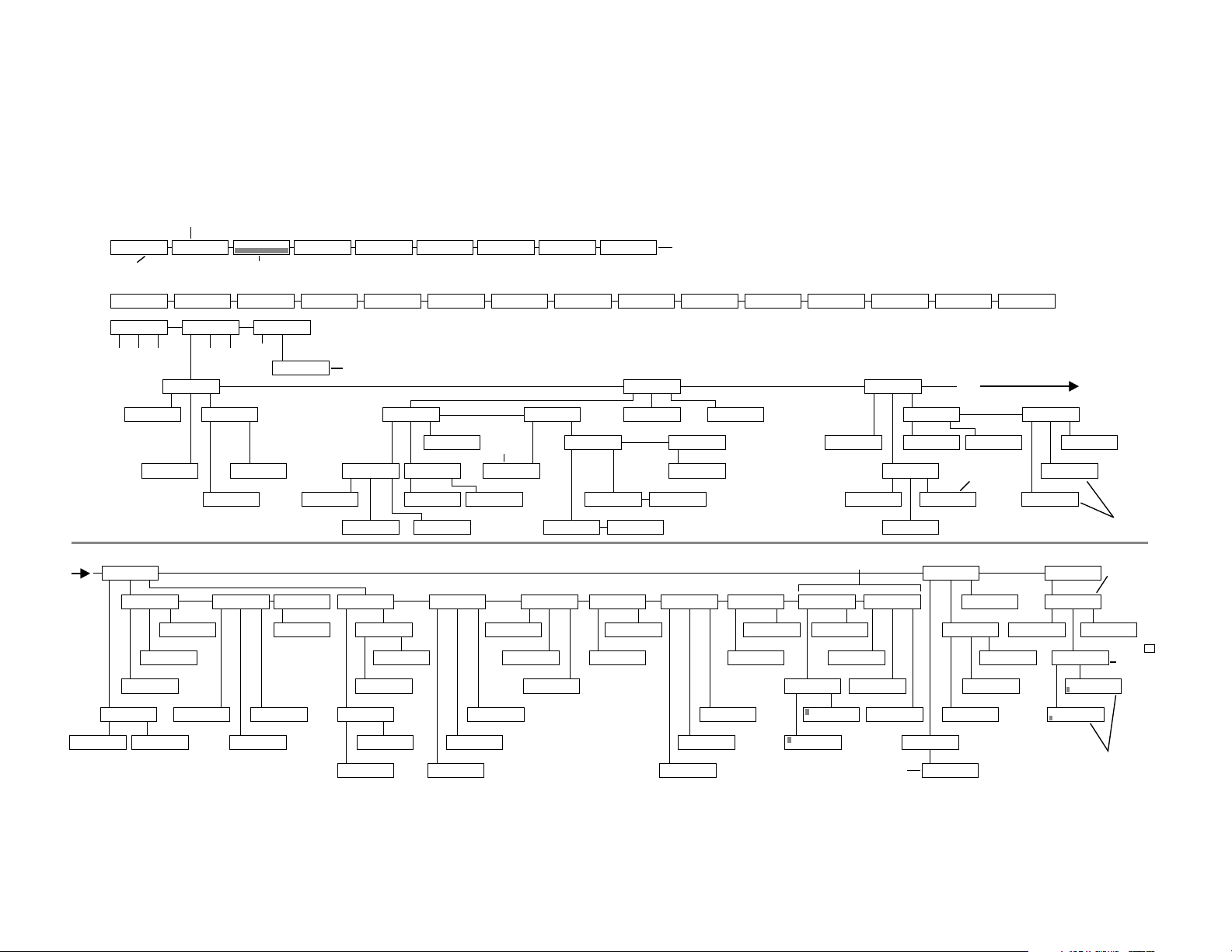
Page 15
Power-on Screen
Appendix E: LCD Flow Chart
DCE-DTE
V.32bis/14.4M
V.32 V4.51/3.25
Software revision levels (may be
different than shown here.)
QUICK SETUP
2-W DIAL (HAYES)
TALK QUICK DIAL
SPEED TYPE
DEC INC
* See reverse side of chart.
Continued
from
SETUP
TEST EIA MODEM
EIA
CTS CD DSR
CTS to EIA
NORM RTS TRUE
TEST OPTIONS
DSR RMT
DSR during ALB
ON OFF
EIA status screen: Not all abbreviations will be present
at same time. (R in upper left corner indicates an incoming ring.)
D TR MR RS CS
TD LINE LEVELS. dBm
9600 TM ER CD RD
QUALITY 000 PKT: SIZE
Bar graph
<1> QUICK SETUP
<1>
****
SETUP
TYPE LINE SPEED
V32
LINE TYPE
2W-D 2W-LL 4W-LL
<4>
<1>
DSR to EIA
NORM TRUE XOVER
CD to EIA
NORM TRUETOGGLE
REMOTE TEST
ENABLE DISABLE
V25 DIAL (Async)
SETUP TEST RMT
<1>
MAX MIN
MAX RATE:
DEC INC
EIA
DTR ALBT RDLT
DTR from EIA
NORMAL TRUE
<2> QUICK SETUP
V25 DIAL (Syn_c)
MAIN MENU
<2>MAIN MENU
RESET RATE
(Resets
modem)
MIN RATE:
DEC INC
19,200
<2>
RDL - DTE Ctrl'ed
ENABLE DISABLE
ALB - DTE Ctrl'ed
ENABLE DISABLE
TX=-09 RX=-24
<3> QUICK SETUP
V25 DIAL (Syn_b)
<3>MAIN MENU
RATE
DOWN UP
0-300
V42 MODE
OFF MANDAT AUTO
EIA
TM
TM to EIA
NORMAL TRUE
STATUS SCREENS
ECHO: msec
<4> QUICK SETUP
This screen is displayed only
if V.32bis mode is selected.
V42
MODE CLASS BREAK
MNP CLASS
DEC INC
<3>
MODEM SETUPS
CDLVL TXLVL
TRANSMIT LEVEL
LEASED DIAL
TX LEVEL
DEC INC
CARRIER DET.
LEASED DIAL
CD LEVEL LEASED
-26 -33 -43
020 1.0
2-W DIAL (DUMB)
V42 CONTROL
V42 SEL BUFFER
5
<1>
TX LEVEL (DL)
PROG PERMIS
0 dBm
LVL
CD LEVEL DIAL
-26 -33 -43
Hz CHANNEL FREQ
OFFSET: 1.0 Hz
The Quick Setup screens are used to quickly select pre-set modem configurations for various applications.
<5> QUICK SETUP
2-W LEASED (ORG)
<1>
BUFFER SELECT
ENABLE DISABLE
V42 SELECTION
PROTOCOL V42bis
LAPM/MNP
DEC INC
BREAK:
DEC INC
MODEM SETUPS
SQ COMEQ TREL
SIGNAL QUALITY
10^3 10^5
THROUGHPUT
<6> QUICK SETUP
V.42bis
ENABLE DISABLE
NDT/NEXP
<2>
TRELLIS CODE
ENABLE DISABLE
COMPR EQUAL
DEC INC
15000 BPS
2-W LEASED (ANS)
V42 CONTROL
DTE FLOW
Set
automatically
in Hayes
mode only.
DTE SPEED:
38,400
DEC INC
MODEM SETUPS
TXCLK T1 RETRN
TRANSMIT CLOCK
INT RX-CLK EXT
T1 timer: 0.8sec
DEC INC
AUTO-RETRAIN
ENABLE DISABLE
T-III
ERTX MODE
255 0233 00
QUICK SETUP MENU
<7> QUICK SETUP
4-W LEASED (ORG)
<2>
FLOW CONTROL
DTE-DCE DCE-DTE
DCE-DTE
NONE CTSon/off
DTE-DCE
RTS
DEC INC
<3>
RATE
V42bis 38400
<8> QUICK SETUP
4-W LEASED (ANS)
SETUP
V42 ADDR DIALER
ADDRESS:
DEC INC
<1>
<1> DCE-DTE
DTE-DCE
DEC INC
MODEM SETUPS
ANS/ORG ANSFREQ
ANSWER TONE
2225Hz 2100Hz
ANS/ORG DEFAULT
ANSWER ORIGINATE
Except for the power-on screen, the data shown on these screens will change,
depending on external conditions and the modem's operational status.
999,999
DC1/DC2 DC1/DC3
CTS
<4>
MODEM SETUPS
FP SPK SPKVOL
FP
ENABLE DISABLE
<9> QUICK SETUP
<2>
FLOW CONTROL
PASSTHRU
PASSTHRU MODE
ENABLE DISABLE
4-WLL V.33
DIALER
DEC INC
<2>
<2>
<5>
SPEAKER VOLUME
LOW MEDIUM HIGH
SPEAKER CONTROL
OFF TILL-CD ON
<10> QUICK SETUP
2-W DIAL (208)
HAYESSPEED LIMIT
These screens are only displayed on models that support these
options. MODEM SETUPS screens may be numbered differently.
MODEM SETUPS
<6>
GUARD V13
V.13
DEC INC
GUARD TONE
550Hz 1800HzOFF
Use INC (increase) and DEC (decrease) to
cycle through digits (0-9); use CTRL to cycle
through dialing control characters(T, *, #, etc.).
<11> QUICK SETUP
2-W DIAL V32/208
AUTO-ANSWER
ENABLE DISABLE
MODEM SETUPS
PSWD
OFF
TRAINING LENGTH
LONG SHORT TER
PASSWORD
CHANGE CLEAR
CONFIRM
DEC SKIP INC
<12> QUICK SETUP
SETUP
ANSWER DATA DISC
DATA FORMAT
SYNC ASYNC
MODEM SETUPS
<7>
CARR CTS RTS-CTS
TRAIN
CARRIER
SWITCH CONSTANT
CTS
RTS ON
CTS DELAY: 0 ms
DEC INC
4-WLL V.29
DATA FORMAT
TYPE LENGTH PAR
CHAR LENGTH
91110
PHONE CELL:
DEC PROG INC
<13> QUICK SETUP
V.29 FAST MASTER
<3>
DISCONNECT
RX TX
RX SPACE DISC'T
ENABLE DISABLE
PARITY:
DEC INC
SETUP
PHONE AUTO LCDI
<8>
AUTO-RECOVERY
SELECT RETN TEST
NO AUTO-RECOVERY
DEC INC
301-555-1234
DEC CTRL INC
<14> QUICK SETUP
Continued below
<1>
TX SPACE DISC'T
ENABLE DISABLE
Set automatically in
Hayes mode only.
NONE
<5>
LCD INTENSITY 5
DEC INC
TEST EVERY 20min
DEC INC
RETURN:
DEC INC
00
<15>
V.29 FAST SLAVE
DISCONNECT
<2>
CARR. CURR. RTS
RTS DISC'T
OFF
DEC INC
CURRENT DISC'T
ENABLE DISABLE
CARRIER DISC'T
ENABLE DISABLE
Hayes mode only: Use S register
S10 to change these options.
<6>
314E
AT
S-REG
DEC INC
ATbefImqvwxy
0102101341
AT&c
Checksum.
If this number
changes, at
least one
option has
been
changed.
AT&c
SETUP
SUMMARY
SUMMARY
SETUPS S-REG
PRI
addr
0011214E0 999 99
AT PROFILES
0 1 &Y0
OFF
ATbefImqvwxy
0102101341
These screens allow for quick option selections.
(Use arrow pushbuttons to view full display.)
For further explanation, see Instruction Manual,
appendix C, Summary Setup.
00:01
Pushing 3
changes
from &Y0
to &Y1
Page 16
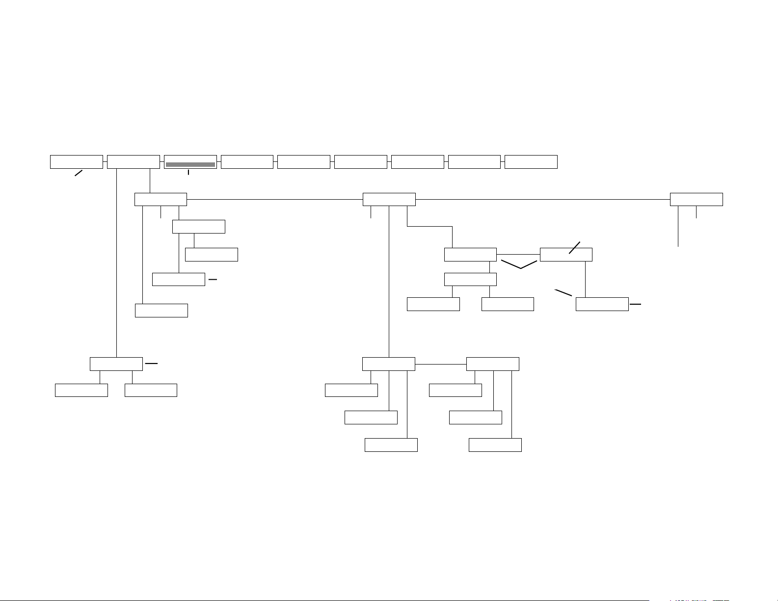
Power-on Screen
Displayed on the
Modem 32144.
V.32bis/14.4M
V.32 V4.51/3.25
Software revision
levels (may be
different than
shown here.)
D TR MR RS CS
9600 TM ER CD RD
TALK QUICK DIAL
MANUAL-DIAL
TALK DATA
TD LINE LEVELS. dBm
QUALITY 000 PKT: SIZE
TX=-09 RX=-24
ECHO: msec
020 1.0
Hz CHANNEL FREQ
OFFSET: 1.0 Hz
THROUGHPUT
15000 BPS
Bar graph
STATUS SCREENS
<1>
AUTO-DIAL
* **
DIAL HANGUPCELL
DIAL FAILURE
NO DTR
DIAL CELL:
DEC DIAL INC
e00
This screen appears only in the
event of a dial failure. Specific
message appears on bottom line.
SETUP TEST RMT
<2>MAIN MENU
REMOT DIGIT LOOP
ON OFF
255 0233 00
REMOTE
CONTROL TEST
REMOTE TEST
RDL RDLST
<1>
RDL SELFTEST
ON OFF
ERTX MODE
V42bis 38400
Displayed only on the
ALX V.32M and ALX
V.32/14.4M.
RATE
REMOTE
CTRL ADDR/C ADDR
Use pushbutton 2 to toggle
between ADDR/C and SLOT/C.
<2>
ADDRESS :
DEC INC
999,999
MAIN MENU
RESET RATE
(Resets modem. LCD
returns to power-on screen,
then EIA status screen.)
If SLOT/C is selected
from REMOTE screen
2 (above), the top line
here will read SLOT
NUMBER: 01.
<3>MAIN MENU
CHECKSUM
MAIN PUMP
MAIN
m1_mt9bf2
V3.02.02
Data displayed here is for use by servicing personnel.
Screens show software revision levels and various
checksums for both the main processor and the data
pump (transmitter, T, and receiver, R). It is unlikely that
the numbers on your unit will match those shown
here—this is normal.
19BB
Pump
V2.03.1 U52 280C
(Accessed by pressing 1
from EIA status screen.)
U51 C5E8
LOCAL TEST
ALB ALBST ST/E
ANALOG LOOPBACK
ON OFF
ANALOG SELFTEST
ON OFF
SELFTEST w/ERROR
ON OFF
<1>
LOCAL TEST
DLB ALBX ALXST
DIGITAL LOOPBACK
ON OFF
ANALOG LOOP (EXT)
ON OFF
ANALOG ST (EXT)
ON OFF
Note: When a test is activated, the EIA status screen will be displayed.
<2>
Page 17
182
MODEM 32144
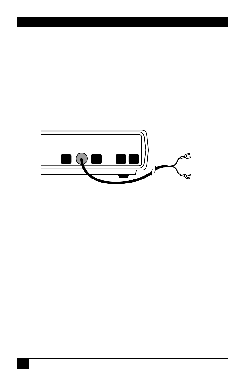
D.2 Installation
Use the supplied cable to attach
the modem to the external DC
power source, as shown in Fig. D-1.
Fig. D-1. Attaching the supplied cable to the DC power source.
Refer also to Section 2.1,
Installation but ignore information
about the AC power transformer
cable.
DIAG
POWER
TX
DIAL
LEASED
LINE
PHONE
Black
Red
Pos. (+)
source
Neg. (-)
source
Page 18

183
APPENDIX D: DC Voltage Models
D.3 Jumper Settings
The power jumpers have been preset at the factory for DC voltage
operation as shown in Tables D-1.
Table D-1. Jumper Settings for -12/-24/-48 VDC Operation
Jumper(s) Setting
JP2 Pins 2 and 3 connected
JP3, JP4 Pins 1 and 2 connected
(set to same position)
For other jumper settings, refer
to the rest of this manual. (But for
the DC modems, ignore the
information in the manuals for
jumpers JP2, JP3, and JP4.)
Page 19

184
MODEM 32144
D.4 Jumper Locations
The jumper locations are shown
below for your information;
however, since the jumper settings
are pre-configured, you should not
have to change them.
Fig. D-2. Partial view of modem circuit board, showing jumper
locations.
For each jumper, pin 1 is
identified by a “1” on the modem
circuit board. (The JP2 pin 1 label
may be difficult to read; JP2 pin 1
is the pin closest to the edge
connector.)
JP6
JP1
JP4
JP3
JP5
JP2
JP8
JP7
Page 20

NOTES
Page 21

NOTES
Page 22

NOTES
Page 23

NOTES
Page 24

NOTES
Page 25

NOTES
Page 26

177
APPENDIX C: Connectors, Adapters, and Jumpers
Figure C-1. Connector Pin Assignments.
All connectors are shown as viewed from the back of the modem.
Pins not included in the listings above are not used.
Dial Line Connector
Pin
Function
3
A/MI
4
1 2 3 4 5 6 7 8
RJ-45
Ring
5
Tip
6
A1/MIC
7
PC
8
PR
REAR PANEL
DTE
DB25
Diagnostic Connector
1 2 3 4 5 6 7 8
RJ-45
Phone Connector
Pin
Function
2
1 2 3 4 5 6
RJ-11
RX
TX
POWER
DIAG PHONE
DIAL
DIAL
3
4
5
LEASED
LINE
A
Ring
Tip
A1
Leased Line
Connector
Pin
Function
2
1 2 3 4 5 6
RJ-11
RXLL
3
TXLL
4
TXLL
5
RXLL
Pin Function
1 Constellation Y Output
2 Constellation X Output
4 Ground (for transmit and
receive data and constellation)
5 Receive Data (output from
modem)
6 Transmit Data (input to modem)
DIAG port always appears to a
system as a DCE port.
Line Connector
(Ignore “RX DIAL” Label)
Pin
1 2 3 4 5 6 7 8
RJ-45
1
2
7
8
Function
TXLL
TXLL
RXLL
RXLL
Alternate Leased
Page 27

178
MODEM 32144
Table C-1. Pin Assignments—DB25 TIA/EIA Interface Connector
Pin Function Designation Source
EIA ITU-T LCD
1 Frame ground—not connected AA 101
2 Transmit (send) data (TD) BA 103 TD DTE
3 Received data (RD) BB 104 RD Modem
4 Request to send (RTS) CA 105 RS DTE
5 Clear to Send (CTS) CB 106 CS Modem
6 Data Set (modem) Ready (DSR) CC 107 MR Modem
7 Signal ground (SG) AB 102 Ground
8 Carrier detect (CD) CF 109 CD Modem
9 Testing voltage, +10V +P Modem
10 Testing voltage, -10V -P Modem
15 Transmit clock (TC) DB 114 Modem
17 Receive clock (RC) DD 115 Modem
18 Analog loopback (ALB) control
1
CN DTE
20 Data terminal ready (DTR) CD 108/2 TR DTE
21 Remote digital loopback (RDL) CN DTE
control
1
22 Ring indicator (RI) CE 125 R Modem
24 External transmit clock (XTC) DA 113 DTE
25 Test mode indicator (TM)
2
CN TM Modem
1
+ voltage activates indicated loopback test (but only if ALB-DTE Ctrl’ed or RDL-
DTE Ctrl’ed option is enabled);—voltage disables test.
2
Alternately, pin 25 may be used for analog loopback (ALB) control.
Page 28

179
APPENDIX C: Connectors, Adapters, and Jumpers
C.2 Jumpers
WARNING
Jumpers should be switched
only by qualified service
personnel.
For most applications, there is no
need to reset the modem’s internal
jumper switches. However, a
jumper switch will have to be reset
if you need to—
Connect frame ground to signal
ground, Switch from A/A1 control
to MI/MIC control, Strap the
modem for use in a DC rack
enclosure, or Change the function
of EIA interface pin 25.
If you need to reset a jumper
switch, refer to the following page
to determine the jumper that
should be switched, where it is
located, and how it should be set.
The jumpers are numbered on the
circuit board; for example, JP4 is
jumper 4. To access the jumpers,
unscrew the four screws on the
bottom of the modem and carefully
lift off the cover.
WARNING
Improper setting of AC and
DC power jumpers could
result in serious damage to
the modem.
Page 29

180
MODEM 32144
Table C-2. Jumper Switch Functions
Jumper(s) Position
1
Function
JP1 FG Frame and signal ground connected
Alternate position Not connected
(no legend)
JP2, JP3 A1 A/A1 control
(Set to same MI MI/MIC control
position)
JP4, JP5, AC AC power
JP8 Alternate position DCpower (for Telco 48 VDC battery)
(Set to same
position)
JP7 TM(output) Pin 25 used as test mode indicator
AL (input) Pin 25 used for analog loopback
1
As indicated by legend printed on modem circuit board.
Factory settings are shown in boldface.
Page 30

167
APPENDIX B: Summary Setup
B.2 Changing Options via Summary
Setup
The appearance of the three setup
screens selected via SETUPS and
AT (profile 0 or 1) is essentially
the same: Brief descriptive
information on the top line and
a long string of numbers on the
bottom line. The numbers are
broken down into groups, with
each group representing a category
of options (dial line options, EIA
interface options, etc.).
Each digit position represents an
option, and the number in each
digit position indicates the current
option setting (parameter). To
change an option setting, use the
front panel pushbuttons to change
the parameter (number), as
explained in the following section.
The diagrams on the following
pages show—
• Which options are included in
each option group
• Which option is indicated by
each digit position within the
group
• The possible parameters for
each option
B.2.1 S
UMMARYSETUPPUSHBUTTON
F
UNCTIONS
The three Summary Setup screens
are different from all other modem
screens in that you can scroll across
the string of numbers; also, the
pushbutton functions are different.
For the three Summary Setup
screens only, the modem
pushbuttons function as follows:
• Pushbutton 1 moves the cursor
to the left. Pushbutton 3 moves
the cursor to the right. If the
cursor is at the end of the
screen, the screen will scroll
one character at a time.
• Pushbutton 2 increments the
blinking value (i.e., the
parameter, or current option
setting). The value will cycle
through the highest possible
parameter value and then back
to 0 or 1.
• The right arrow button moves
the screen to the beginning of
the next group of options to
the right. The left arrow button
moves the screen to the
beginning of the next group of
options to the left. Groups of
options are separated by blank
spaces on the LCD.
Page 31

000
MODEM 32144
NOTE
On the Summary Setup
screens that show AT
profiles 0 and 1, the cursor
location is indicated by a
solid black box when the
cursor is positioned in a
blank cell (one with no
characters).
B.2.2 E
XPLANATION OF
S
UMMARY
S
ETUPSCREENS
Note that options are identified on
the Summary Setup screens only by
the relative positions of the
numbers within the number string,
as indicated in the following
diagrams. Each digit position
represents an option, and the
number in each digit position
indicates the current option setting
(parameter).
The string of numbers in each
diagram shows the factory default
setting for each option (i.e., the
Hayes mode default settings). Each
diagram also identifies all possible
settings for each option.
NOTE
Numbers that are not
identified in the following
diagrams represent option
settings that are reserved
for future use or factory use.
These settings should not
be changed.
168
Page 32

169
APPENDIX B: Summary Setup
Fig. B-1. Primary Options.
PRI
NOTES: Speed limit, min., and speed limit, max.: 7200 bps parameters
are available only if V.32bis mode is enabled.
ALX V.32 and ALX V.32M only: Available speed limit selections: Max., 0-7 and A;
min., 0=6 and 9. Default max. speed limit setting: 0 (9600 bps).
Speed type: Settings 0, 1 and 3 are not available on all all ALX models.
258021210
Speed type: 0=Auto (V.32/208), 1=V.33, 2=V.32/32bis, 3=Bell 208
Speed limit, min. (bps): 0=9600, 1=4800, 2=2400,3=1200
4=600, 5=0-300,6=1200/75,7=14,400, 8=12,000, 9=7200
Speed limit, max. (bps): 0=9600,1=4800,2=2400,3=12000,4=600,
5=0-300, 6=EIA-23, 7=1200/75, 8=14,400,9=12,000,A=7200
Buffer mode/speed conversion: 0=enable, 1=disable
V.42 mode : 0=off, 1=mandatory, 2=automatic
Dialer mode: 0=off, 1=Hayes, 2=DTR dialing;
3=V.25bis, async; 4=V.25bis, sync, character-oriented;
5=V.25bis, sync, bit-oriented; 6=Penril mode
Character length (bits): 0=8, 1=9, 2=10, 3=11
Data format: 0=sync, 1=async
Line type: 0=2--wire dial, 1=2-wire leased, 2=4-wire leased
LCD
Page 33

170
MODEM 32144
Fig. B-2. Address.
Fig. B-3. Dial Line Options.
a d d r
address
dial
0 0 0 0 0 0 1 0 2 1 0
9 9 9
Group
9 9 9
Unit
address
Pulse dialing rate (pulse per sec): 0=10, 1=20
Wait for carrier (sec): 0=30, 1=45, 2=60, 3=75
T1 timer (sec): 0=0, 1=0.3, 2=0.8, 3=1.6, 4=3.
Carrier detect level, dial (dBm): 0= -51, 1= -41, 2= -34
TX level, dial: 0=programmable, 1=permissive
Disconnect, RTS (sec): 0=off, 1=20, 2=40 . . .7=140
Disconnect, line current: 0=enable, 1=disable
Disconnect, carrier: 0=enable, 1=disable
Disconnect, TX space: 0=enable, 1=disable
Disconnect, RX space: 0=enable, 1=disable
Auto-answer: 0=enable, 1=disable
Page 34

171
APPENDIX B: Summary Setup
Fig. B-4. EIA Interface Options.
Fig. B-5. V.42 Error Correction Options.
eia
0 1 0 1 1 1 0 0 0
CD and DSR delay: 0=disable, 1=enable
Test mode: 0=normal, 1=true
Remote digital loopback test: 0=enable, 1=disable
Analog loopback test: 0=enable, 1=disable
CTS: 0=normal, 1=follow RTS, 2=true, 3=on
Carrier detect: 0=normal, 1=true, 2=toggle
DSR: 0=normal, 1=true, 2=crossover
DTR: 0=normal, 1=true
V.42 <1> V.42 <1>
2 0 0 0 0 1 0 2 10 0 3 3 5 3 1 1
V.42bis: 0=enable, 1=disable
V.42 protocol: 0=LAPM only, 1=MNP only, 2=LAPM/MNP
DTE pass-through flow control: 0=enable, 1=disable
Flyback buffer: 0=enable, 1=disable
Break handling: 0=none, 1=destr./expedited, 2=non-destr./expedited,
3=non-destr./non-expedited
MNP class (limit): 1=class 1, 2=class 2, 3=class 3, 4=class 4, 5=class 5
Flow control, DCE to DTE: 0=none, 1=CTS, 2=DC1/DC2, 3=DC1/DC3
Flow control, DTE to DCE: 0=none, 1=RTS, 2=DC1/DC2, 3=DC1/DC3
Parity: 0=none, 1=odd.2=even, 3=mark, 4=space
DTE speed (bps): 0=38,400, 1=19,000, 2=9600, 3=4800, 4=2400,
5=1200, 6=600, 7=300, 8=110
"V.42 <1>" and "V.42 <2>" are displayed
to help indicate the relative position of
individual options across the LCD.
Link flow control: 0=disable, 1-enable, 2=slaved
DCE pass-through flow control: 0=disable, 1=enable
Selective retransmission: 0=disable, 1=enable
Page 35

172
MODEM 32144
Fig. B-6. Leased Line Options.
L. L.
1 0 0 2 0 0 1 0
Auto-recovery test interval (min): 0=10, 2=40, 3=60
Auto-recovery return (sec): 0=off, 1=10, 2=40, 3=60, 4=120
Auto-recovery select: 0=none, 1=dial if bad 1 min ... 4=dial if bad 4 min,
5=dial if bad 30 sec 96-8 not used), 9=manual recovery
Carrier detect level, leased (dBm): 0= -43, 1= -33, 2=-26
TX level, leased (dBm): 0=0, 1= -1... 9= -9, A= -10 ... F= -15
TX clocking: 0=internal, 1=received clocking, 2=external
Answer/originate: 0=answer, 1=originate
Page 36

173
APPENDIX B: Summary Setup
Fig. B-7. Data Pump 1 Options.
pump 1
Fig. B-8. Data Pump 2 and 3 Options.
2 0 0 2 1 0 3 0 0 0 1
"pump1," "pump2," and "pump3" are displayed to help indicate
the relative positions of individual options across the LCD.
The "pump2", and "pump3" options are identified below.
Phase reversal in answer tone: 0=enable, 1=disable
Auxiliary channel: 0=enable, 1=disable
Speed fallback: 0=enable, 1=disable
Trellis coding: 0=enable, 1=disable
Answer tone: 0=2225 Hz, 1=2100 Hz
Guard tone: 0=550 Hz, 1=1800 Hz, 2=off
Auto-retrain: 0=enable, 1=disable
Signal quality level (error/bits): 0=1 in 10^3, 1=1 in 10^5
Compromise equalizer type: 0=I, 1=II< 2=III, 3=IV, 4=off
pump 2
0 0 0 0 0 1 1 0 0 0
8
6
5
Turnaround delay: 0=disable, 1=enable
4
Satellite delay: 0=disable, 1=enable
3
RTS-to-CTS delay (ms): 0=none, 1=15, 2=50, 3=150
2
1
CTS: 0=always ON, 1=follow RTS
Carrier type: 0=switched, 1=constant
pump 3
0 0 0 0 0 1 0 0
8
V.26 scrambler: 0=disable, 1=enable
7
Anti-streaming timer: 0=disable, 1=enable
6
5
4
3
2
1
10
Forward rate renegotiation: 0=disable, 1=enable
9
Retrain threshold (error/bits): 0=10^4, 1=10^6
208 phase detection: 0=normal, 1=compensated
Rate renegotiation (RRP): 0=disable, 1=enable
V.26 dibit encoding: 0=alternative A, 1=alt. B
Echo protection tone: 0=disable, 1=short, 2=long
V.27bis 2400-bps alternatives: 0=alternative i, 1=alt. ii
V.3x/208 auto-detect mode: 0=disable, 1=enable
V.22bis S1 duration (ms): 0=100, 1=150
Fast connect 103 mode: 0=disable, 1=enable
Page 37

174
MODEM 32144
Fig. B-9. Miscellaneous Options.
"misc1," "misc2," and "misc3" are displayed to help indicate
misc 1
1 2 3 0 0 0 0
misc 2 misc 3
0 1 0 0 0 0 0 F F F F 1 0 0 0 0 0 0 0 0
the relative positions of individual options across the LCD.
The "misc2", and "misc3" options are identified below.
Op. mode fallback: 0=Bell 212A and 103, 1=V.22/V.21/V.23
Remote test: 0=enable, 1=disable
DSR during ALB: 0=enable, 1=disable
FP: 0=enable, 1=disable
LCD intensity: 0, 1... 7 (7=greatest intensity)
Speaker volume: 0=low, 1=medium, 2=high
Speaker control: 0=on, 1=on till CD, 2=off
Low-profile DIAG LED:
0=Connect status, 1=DTR status
CFI AB response on disconnect:
0=disable, 1=enable
Wait for MNP link request (sec): 0=3, 1=7
Leased line interrupt:0=off, 1=on
Remote RTS signaling: 0=off, 1=on
Multimode handshake: 0=T1 timer,
1=V.32bis Annex A
Answer tone detection: 0=enable, 1=disable
Answer tone detection: 0=enable, 1=disable
V.13 operation: 0=off, 1=TX only, 2=RX only, 3=TX and RX
DTE=DCE speed: 0=disable, 1=enable
Penn/V.25bis DTR dialing: 0=enable, 1=disable
Page 38

175
APPENDIX B: Summary Setup
Fig. B-10. Hayes Mode Options—For Each AT Profile.
AT commands
ATbeflmqvxy
110210141
AT & commands
AT&cdgjlpqrsx
1200000000
S registers
s00 s18 s25 s26
001 000 005
Flow control, DCE
Flow control, DTE
Load inactivity timer
AT/ commands
(most are for
V.42 options)
AT/abcdfkmnpq t vx
315013032330011
Page 39

157
APPENDIX A: Quick Setup Configurations
Table A-1. Quick Setup Configurations
Page 40

158
MODEM 32144
Table A-1. Quick Setup Configurations (continued)
Page 41

159
APPENDIX A: Quick Setup Configurations
Table A-1. Quick Setup Configurations (continued)
Page 42

160
MODEM 32144
Table A-1. Quick Setup Configurations (continued)
Page 43

161
APPENDIX A: Quick Setup Configurations
Table A-2. Additional Quick Setup Configurations
Default settings listed by Quick Setup mode
Option Bell 4-wire V.29 V.29
208
1
leased fast fast
V.29 master slave
Communication Standard option
STD 208 V.29 V.29 V.29
Speed Limit option, V.32, V.32M, V.32/14.4, V.32/14.4M, V.32/19.2, V.32/19.2M
MAX DCE 4800 9600 9600 9600
RATE
MIN DCE 4800 4800 4800 4800
Default settings listed by Quick Setup mode
Option Bell 208
1
4-wire V.29 fast V.29 fast
leased V.29 master slave
BUFFER Disable Disable Disable Disable
DTE SPEED 38.4 Kbps 38.4 Kbps 38.4 Kbps 38.4 Kbps
FLOW RTS RTS RTS RTS
CONTROL
DTE-DCE
FLOW CTS CTS CTS CTS
CONTROL
DCE-DTE
DTE Disable Disable Disable Disable
PASS-THRU
FLOW CTRL
Page 44

162
MODEM 32144
Table A-2 (continued). Additional Quick Setup Configurations
(Miscellaneous)
ADDRESS2999,999 999,999 999,999 999,999
DIALER OFF OFF OFF OFF
MODE
AUTO Enable Enable Disable Disable
ANSWER
Data Format Options
DATA TYPE Sync Sync Sync Sync
CHAR 10 10 10 10
LENGTH
PARITY None None None None
Disconnect Options
RX SPACE Disable Disable Disable Disable
DISC’T
TX SPACE Disable Disable Disable Disable
DISC’T
CARRIER Enable Enable Enable Enable
DISC’T
LINE CURR Enable Enable Enable Enable
DISC’T
RTS DISC’T OFF OFF OFF OFF
2
Quick Setup does not change the address to the default address, but a factory
reset does.
Page 45

163
APPENDIX A: Quick Setup Configurations
Table A-2 (continued). Additional Quick Setup Configurations
Test Options
DSR ON ON ON ON
DURING
ALB
REMOTE Enable Enable Enable Enable
TEST
EIA Options
CTS to EIA Normal Normal Normal Normal
CD to EIA Normal Normal Normal Normal
DSR to EIA Normal True True True
DTR from EIA Normal True True True
ALBT DTE Disable Disable Disable Disable
CTRL’ED
RDL DTE Disable Disable Disable Disable
CTRL’ED
TM to EIA True True True True
Modem Setup Options
CD LEVEL, -26 dBm -26 dBm -26 dBm -26 dBm
LEASED
CD LEVEL, -43 dBm -43 dBm -43 dBm -43 dBm
DIAL
TX LEVEL, 0 dBm 0 dBm 0 dBm 0 dBm
LEASED
TX LEVEL, Permis. Permis. Permis. Permis.
DIAL
SIGNAL 10
4
10
4
10
$
10
4
QUAL LEVEL
Page 46

164
MODEM 32144
Table A-2 (continued). Additional Quick Setup Configurations
COMPR T-III T-III T-III T-III
EQUAL
TRELLIS Enable Enable Enable Enable
CODE
TRANSMIT Internal Internal Internal Internal
CLOCKING
T1 TIMER 0.8 sec 0.8 sec 0.8 sec 0.8 sec
Default settings listed by Quick Setup mode
AUTO- Enable Enable Disable Disable
RETRAIN
ANS/ORG ORIG ORIG ORIG ANS
DEFAULT
ANS TONE 2100 Hz 2100 Hz 2100 Hz 2100 Hz
FRONT Enable Enable Enable Enable
PANEL
SPKR CTRL Til-CD Til-CD Til-CD Til-CD
SPKR VOL Medium Medium Medium Medium
GUARD OFF OFF OFF OFF
TONES
V.8 PROC Enable Enable Enable Enable
V.13 OFF OFF OFF OFF
OPERATION
TRAINING Long Long Short Short
LENGTH
CARRIER Switched Constant Constant Switched
CTS RTS RTS RTS RTS
RTS-CTS DLY 150 ms 0 0 0
Page 47

165
APPENDIX A: Quick Setup Configurations
Table A-2 (continued). Additional Quick Setup Configurations
Auto-Recovery Options
AUTO-RECV None None None None
SELECT
AUTO-RECV OFF OFF OFF OFF
RETURN
AUTO-RECV 20 min 20 min 20 min 20 min
TEST INT’VL
AUTO-RECV INTER INTER INTER INTER
TEST TYPE
LCD Intensity Option
LCD55 55
INTENSITY
Page 48

166
MODEM 32144
Do not Make PDF of this page
Page 49

6
MODEM 32144
3.3 Selecting Options from the Front Panel ........................................40
3.3.1 DEC/INC (Decrease/Increase) Screens ..............................41
3.3.2 Example of How to Select an Option ...................................42
3.3.3 How to Return to the EIA Status Screen ..............................43
3.3.4 Automatic Configuration Save Feature.................................43
3.3.5 How to Return to Default Settings ........................................43
3.4 Options..............................................................................................44
3.5 Speed (Data Rate) Options .............................................................44
3.6 V.42 Error Correction Options........................................................48
3.7 Address..............................................................................................54
3.8 Dialer Mode ......................................................................................55
3.9 Auto-Answer Option ........................................................................55
3.10 Data Format Options .....................................................................56
3.11 Disconnect Options........................................................................57
3.12 Test Options.....................................................................................58
3.13 EIA Options .....................................................................................58
3.14 Modem Setups................................................................................60
3.15 V.33 and Bell 208A/B Options ......................................................65
3.16 Options Accessible Only via Summary Setup...............................67
3.16.1 Dial Line Options .................................................................67
3.16.2 V.42 Error-Correction Options ............................................67
3.16.3 Data Pump Options..............................................................69
3.16.4 Miscellaneous Options .........................................................70
4.0 General Operation and Special Features..............................................74
4.1 Quick Reset.......................................................................................74
4.2 Storing Phone Numbers ..................................................................74
4.2.1 Uses..........................................................................................74
4.2.2 How to Store a Phone Number .............................................75
4.3 Automatic Fallback...........................................................................77
4.3.1 Operating-Mode Fallback ......................................................77
4.3.2 Automatic Rate Adjustment...................................................79
4.4 Dumb Mode and Bell 208 Operation.............................................80
4.4.1 Manual Originate/Answer Operation ..................................80
4.5 V.32/208 Auto-Detect Mode............................................................81
4.5.1 V.32/V.32 bis Operation.........................................................81
4.5.2 Bell 208 Operation .................................................................82
4.5.3 Automatic Fallback.................................................................82
4.6 V.13 Operation .................................................................................82
4.7 DTR Dialing......................................................................................82
4.7.1 Dialing a Stored Number.......................................................83
4.7.2 Answer Mode Operation........................................................83
Page 50

7
MODEM 32144
4.8 Dial Line Auto-Recovery ..................................................................83
4.8.1 Setting Up the Modem for Dial Line Auto-
Recovery ..................................................................................83
4.8.2 Recovery Procedure ...............................................................84
4.9 Leased Line Auto-Recovery .............................................................84
4.9.1 Autodial Backup .....................................................................85
4.9.2 Exit from Leased Line Auto-Recovery ..................................85
4.9.3 Leased-Line Auto-Recovery Options.....................................86
4.10 Modem Security Operation...........................................................87
4.11 Automatic Password Protection (APP)..........................................87
4.12 Configuring Modems for APP.......................................................89
4.12.1 APP Without Callback ..........................................................89
4.12.2 APP With Callback................................................................89
4.12.3 Password Screens ..................................................................89
4.12.4 Valid Password Characters ...................................................90
4.12.5 APP with Callback: Storing the Password with
Callback Number..................................................................91
4.13 Disabling APP .................................................................................91
4.13.1 Temporarily Disabling APP..................................................91
4.13.2 Clearing the Password ..........................................................92
4.14 Manual-Response Password Protection (MPP)............................92
4.15 Commands for Enabling MPP.......................................................93
4.16 How to Use Password Commands.................................................94
5. Hayes Emulation Mode ............................................................................97
5.1 Hayes Mode Autodialer ...................................................................97
5.1.1 Enabling the Hayes Mode Autodialer...................................97
5.1.2 Command Guidelines ............................................................97
5.2 Result Codes .....................................................................................99
5.3 Transmission Speed........................................................................100
5.4 Hayes Compatible Commands......................................................101
5.5 S Registers .......................................................................................107
5.5.1 Reading and Setting Registers.............................................107
5.5.2 S Register Functions.............................................................108
5.6 Saving Option Selections...............................................................110
5.7 Facsimile (Fax) Transmission ........................................................111
5.8 Hayes Mode Reference Tables ......................................................111
6. V.25bis Autodialer ...................................................................................127
6.1 Enabling the V.25bis Autodialer....................................................127
6.1.1 Quick Setup ..........................................................................127
6.1.2 2=Dialer Mode (DIAL V.25 bis Screen) ..............................128
6.1.3 DTR Dialing in V.25 bis Mode .............................................128
6.2 V.25 bis Autodialer Commands .....................................................128
6.3 Dialing Parameters.........................................................................132
6.4 V.25 bis Result Codes .....................................................................134
Page 51

8
MODEM 32144
6.5 Message Format..............................................................................136
6.5.1 Asynchronous........................................................................136
6.5.2 Synchronous, Character-Oriented ......................................136
6.5.3 Synchronous, Bit-Oriented ..................................................137
7. Diagnostics...............................................................................................138
7.1 When and Why to Test ...................................................................138
7.2 Symptoms and Scope of the Problem...........................................138
7.3 Physical Inspection.........................................................................139
7.4 Overview of Modem Diagnostics...................................................139
7.5 How to Select and Activate Tests ...................................................140
7.5.1 Front-Panel Control .............................................................140
7.5.2 Running Tests in Hayes Mode .............................................140
7.5.3 Remote Test Control ............................................................140
7.6 Diagnostic Monitoring: Status Screens........................................140
7.6.1 EIA Status Screen .................................................................140
7.6.2 Other Status Screens ............................................................141
7.7 Rate Change Screen.......................................................................143
7.8 Local Modem Diagnostics .............................................................144
7.8.1 Analog Loopback (ALB) Test..............................................144
7.8.2 Analog Loopback Self-Test (ALBST) ..................................145
7.8.3 Analog Loopback Self-Test with Errors (ST/E) .................147
7.8.4 External Analog Loopback (ALBX) Test............................147
7.8.5 External Analog Loopback Self-Test (ALXST) ..................149
7.8.6 Digital Loopback Test (DLB) ..............................................151
7.9 Remote Modem Diagnostics..........................................................153
7.9.1 Remote Digital Loopback (RDL) Test ................................153
7.9.2 Remote Digital Loopback Self-Test (RDLST) ....................154
Appendix A: Quick Setup Configurations ................................................156
Appendix B: Summary Setup.....................................................................166
B.1 Summary Setup LCD Screens .......................................................166
B.2 Changing Options via Summary Setup ........................................167
B.2.1 Summary Setup Pushbutton Functions..............................167
B.2.2 Explanation of Summary Setup Screens ............................168
Appendix C: Connectors, Adapters, and Jumpers ...................................176
C.1 Connectors and Adapters .............................................................177
C.1.1 Connector Pin Assignments................................................178
C.2 Jumpers...........................................................................................179
Page 52

9
MODEM 32144
Appendix D: DC Voltage Models ...............................................................181
D.1 Introduction...................................................................................181
D.2 Installation .....................................................................................182
D.3 Jumper Settings .............................................................................183
D.4 Jumper Locations ..........................................................................184
Appendix E: LCD Flow Chart ....................................................................185
Page 53

139
CHAPTER 7: Diagnostics
7.3 Physical Inspection
The next step in isolating a
defective component is to inspect
the system. If you have been able to
trace the problem to a specific site,
examine that site. Check the
installation of the modem and
DTE. Are all cables in good
condition and fully connected?
Are all components in the system
receiving power? Inspect the
system as thoroughly as possible.
7.4 Overview of Modem Diagnostics
Once you have identified the
symptoms and conducted a
physical inspection of the sites in
question, you can use diagnostic
monitoring and testing to further
isolate the problem. The modem is
equipped with diagnostic
capabilities that will often enable
the user to locate faults quickly and
easily. The diagnostic features of
the modem fall into two
categories—local and remote—
as listed below.
There are six types of local
modem diagnostics:
• Analog loopback (ALB)
• Analog loopback self test
(ALBST)
• Analog loopback self test with
errors (ST/E)
• External analog loopback
(ALBX)
• External analog loopback self
test (ALXST)
• Digital loopback (DLB)
There are two types of remote
diagnostics:
• Remote digital loopback (RDL)
• Remote digital loopback self
test (RDLST)
The sequence in which
diagnostic tests should be
conducted depends upon the
symptoms that have been identified
as well as the availability of
personnel at the remote site and
external test equipment. The self
test pattern generator and pattern
detector built into the modem
alleviates the requirement for
external test equipment. With the
non-self tests, either a standard
DTE or an external bit error rate
test (BERT) is used to generate test
data and compare it with received
data.
Because more transmission
errors occur at higher speeds on
marginal transmission facilities,
begin testing at 14.4 Kbps. If errors
occur, reduce the speed and try
again. If you cannot correct the
problem, contact Technical
Support for assistance.
Page 54

140
MODEM 32144
7.5 How to Select and Activate Tests
7.5.1 F
RONT-PANELCONTROL
Tests are accessed and activated in
the same way options are selected:
by using the LCD and front-panel
pushbuttons (as explained in
Chapter 3). To find the LCD screen
for a specific test, refer to the LCD
flow chart (DIAGNOSTIC AND
CONTROL FUNCTIONS)
included with this manual. Once
you have accessed the screen for a
specific test, press pushbutton 1 to
begin the test (select ON). A test
status screen will then be
automatically displayed. To
deactivate a test, press the ENT
pushbutton and then pushbutton
3. (The ENT button cannot be
used to exit the text screen until
the test has been deactivated.)
NOTE
For valid test results, error
correction must be disabled
before diagnostic tests are
run. To disable error
correction, set the V.42
Mode option to OFF.
7.5.2 R
UNNINGTESTS INHAYESMODE
In Hayes emulation mode only,
most of the diagnostic tests
available on the modem can be
activated via the DTE keyboard by
using the &T commands listed in
Section 5.4. The duration of a test
can be set by assigning a value to
register S18. For example, AT
S18=30 sets the test time to 30
seconds. The command &TO
terminates a test. For further
information, see Section 5.4.
7.5.3 R
EMOTETESTCONTROL
You can configure the modem to
ignore or accept requests from
remote modems to initiate tests on
your modem. To access the remote
test control option, select TEST
from SETUP screen 4. Then select
RMT from the TEST OPTIONS
screen. From the REMOTE TEST
screen, select ENABLE to allow
remote test initiation or DISABLE
to refuse remote test requests.
7.6 Diagnostic Monitoring: Status
Screens
To obtain additional information
about the status of the
communications system, observe
the status screen described in the
following sections. To view these
screens, push the ENT button until
the EIA status screen appears. Use
the right arrow pushbutton to
advance to other status screens.
7.6.1 EIA S
TATUSSCREEN
The EIA status screen indicates the
operational status of the modem as
well as the condition of certain EIA
RS-232 leads. The abbreviations
that may appear are identified
below; however, typically, only a few
of these abbreviations will be
displayed during actual operation.
Page 55

141
CHAPTER 7: Diagnostics
DTRMRRSCSTD
9600 TM ER CD RD
Handshake Display
When two modems establish a
connection, they engage in an
exchange known as a handshake.
While a handshake is taking place,
the modem displays several codes
ranging from H-01 to H-28 in the
lower left corner of the EIA status
screen. A handshake typically lasts
for up to 12 seconds and is
accompanied by various audible
tones.
Checksum Screens
By pressing pushbutton 1 while the
EIA status screen is displayed, you
can access two checksum screens,
one for the main checksum and
one for the data pump transmitter
and receiver checksums. These
checksums provide data intended
for use by servicing personnel. The
checksum screens also show the
software revision levels (which are
also shown on the power-on
screen).
7.6.2 O
THER
S
TATUSSCREENS
QUALITY SCREEN. The quality
screen displays the quality of the
received signal carrier as a numeric
value and as a horizontal bar
graph. A low numeric value
indicates good signal quality. The
best possible signal quality is
indicated when the bar graph
extends all the way to the right
edge of the LCD.
D=Dial line occupied
R=Ringing (R appears in same
position as D.)
S=Connection secured by security
handshake (S appears in same
position as D. S and D may flash
alternately.)
TR=Data Terminal Ready
MR=Data Set Ready
RS=Request to Send
CS=Clear to Send
TD=Transmit Data
9600, 4800, etc. = Data speed
(“idle”—meaning the modem is
off-line—or H-01, H-14, etc., may
also be displayed in the data speed
position; see following text.)
TM=Test mode
ER=Error (poor signal quality)
CD=Carrier Detect
RD=Receive Data
Page 56

142
MODEM 32144
LINE LEVELS SCREEN. This
screen shows the preset level of the
transmit signal (TX) and the
measured level of the receive
signal (RX).
The RX value is the approximate
local receive level of the incoming
signal. The range of measurement
for RX is from 0 to –43 dBm in 1.5dBm increments. If the signal level
is less than the carrier detect
threshold, <CD will be displayed.
ECHO CHARACTERISTICS
SCREEN. This screen displays the
characteristics of the echo portion
of the receive signal. Specifically, it
shows milliseconds of delay and the
offset frequency in Hertz.
CHANNEL FREQUENCY
OFFSET. This screen displays the
frequency offset of the receive
signal in Hertz.
THROUGHPUT SCREEN. This
screen functions only if error
correction has been enabled. It
shows the rate (in bits per second)
at which characters are being
accepted by the modem from the
DTE.
PACKET SCREEN. The packet
screen functions only when error
correction is enabled. It has three
components, as explained next.
• SIZE. Shows size of data packets
(MNP) or blocks (V.42/V.42
bis) currently being
transmitted. MNP uses
“shorter” packets to transmit
through noisy lines and
“longer” packets (which allow
greater throughput) when line
conditions are good. The
maximum MNP packet size is
256 characters (MNP classes 4
and 5) or 64 (MNP classes 1-3).
The block size for V.42/V.42 bis
is fixed at 128 characters.
• TRANSMITTED (TX). Number
of packets or blocks transmitted
since the connection was
established (or since counter
reset).
• ERRORS (ER). Number of
retransmissions (due to data
errors) since the connection
was established (or since the
counter was reset).
To reset the TX and ER counters,
press pushbutton 2 while the
packet screen is displayed.
MODE AND RATE SCREEN.
This screen shows the following
data:
• MODE. Below MODE, this
screen indicates the errorcorrection status:
- NORMAL, Error correction and
buffer mode are both inactive.
Page 57

143
CHAPTER 7: Diagnostics
- V42, V.42 error correction
(LAPM) is active.
- V42 bis, V.42 bis error correction
(LAPM with data compression)
is active.
- MNP 01 – MNP 05, MNP error
correction is active.
- BUFFER, Buffer mode is active.
- OFFLINE, Modem is off-line.
• RATE. This screen shows the
data rate of the DTE.
7.7 Rate Change Screen
If V.32bis mode and the Rate
Renegotiation Procedure (RRP)
option are both enabled, the
modem will automatically adjust
during data transmission to a
higher or lower data rate,
depending on the receive signal
quality. For diagnostic purposes,
the RATE screen (accessed from
screen 3 of the MAIN MENU) may
be used to manually initiate speed
renegotiation from the front panel,
as explained below.
The RATE screen is displayed
only if V.32 bis mode is enabled
(via Summary Setup, V.32 Mode
option).
If you select DOWN from the
RATE screen, the modem will fall
back to the next lower speed. If you
select UP, the modem will fall
forward to the next higher speed—
if the signal quality is good enough.
The range within which the
modem can fall forward or fall
back is limited by the minimum
and maximum rates set via the
Speed Limit option. After you
select UP or DOWN, the LCD will
automatically switch to the EIA
status screen so you can see the
result of the rate change request
(i.e., the current data rate, which is
displayed in the lower left corner of
the EIA status screen). However, if
the local modem has reached the
minimum or maximum speed, it
will not switch to the EIA status
screen.
NOTE
A request to increase the
data rate may result in no
change in the data rate if the
signal quality is poor.
If you manually initiate speed
renegotiation with RRP enabled,
the modem will automatically
renegotiate the speed (again) after
receiving good signal quality for
4 seconds. If the originate modem
attempts to negotiate a rate that
is lower than the minimum rate
setting of the answer modem, the
answer modem will disconnect
(GSTN cleardown).
Page 58

144
MODEM 32144
7.8 Local Modem Diagnostics
Local modem diagnostics are for
testing the modem and its adjoining system. These tests are accessed
from the main menu and are easily
performed if the modem is
attached to DTE or an external
BERT.
7.8.1 A
NALOGLOOPBACK
(ALB) T
EST
Analog loopback testing allows the
user to test the local modem and its
associated terminal independently
from the telephone interface and
the remote modem. Fig. 7-1 shows
the connections automatically
made during the test.
LOCAL MODEM
DATA TERMINAL EQUIPMENT
(DTE) AT LOCAL SITE
TRANSMITTER
RECEIVER
Fig. 7-1. Analog Loopback Test.
Page 59

145
CHAPTER 7: Diagnostics
In Hayes emulation mode only,
the ALB test can be initiated using
the command &T1 (preceded by
AT). In any mode, the ALB test can
be initiated by using the modem’s
front panel controls, as explained
in the following paragraphs.
Make sure the modem is idle,
that the data rate is the same as
that of the DTE and that the DTR
circuit is on. (If TR is present on
the EIA status screen, the DTR
circuit is on.)
From screen 2 of the LCD MAIN
MENU, select TEST. This will take
you to screen 1 of the LOCAL
TEST menu, where ALB will be
displayed as one of the test
selections. Select ALB.
The ANALOG LOOPBACK
screen will be displayed, with ON
and OFF as the possible selections.
Select ON to activate the test. (In
general, the DSR during ALB test
option discussed in chapter should
be left ON—the default selection—
to avoid disrupting the DTE and
DTE software operations.)
The EIA status screen will be
displayed while the test is being
conducted. Ensure that test data
is being generated. Watch for data
errors. By transmitting test data
and comparing it with the received
copy, the DTE and modem are
checked for proper operation.
To end the test, press the ENT
pushbutton to return to the
ANALOG LOOPBACK screen,
and then select OFF.
7.8.2 A
NALOGLOOPBACKSELF-TEST
(ALBST)
In the analog loopback self-test,
the modem is placed in analog
loopback and data is sent and
received by an internal 511-bit
pattern generator and receiver;
therefore, no DTE or external
BERT is necessary. Fig. 7-2 shows
the data flow for this test.
Page 60

146
MODEM 32144
Fig. 7-2. Analog Loopback Self Test (ALBST).
The SELFTEST screen will be
displayed, with ON and OFF as the
possible selections. Select ON to
activate the test. The EIA status
screen will be displayed while the
test is being conducted. If “ER” is
present on the front panel, data
errors have occurred. The ER
indicator may flash on when the
test is first turned on, but it should
quickly go out and remain off until
the end of the test.
In Hayes mode only, the
ALBST can be initiated using the
command &T8 (preceded by AT).
In any mode, the ALBST can be
initiated by using the modem’s
front-panel controls, as follows:
From screen 2 of the LCD MAIN
MENU, select TEST. This will take
you to screen 1 of the LOCAL
TEST menu, where ALBST will
be visible as one of the selections.
Select ALBST.
TRANSMITTER
PATTERN
GENERATOR
RECEIVER
PATTERN
DETECTOR
Page 61

147
CHAPTER 7: Diagnostics
To end the test, press the ENT
pushbutton to return to the
SELFTEST screen, and then
select OFF.
7.8.3 A
NALOGLOOPBACKSELF-TEST
WITH
E
RRORS
(ST/E)
In the analog loopback self test
with errors, data is sent and
received by an internal 511-bit
pattern generator and receiver;
therefore, no DTE or external
BERT is necessary. This test differs
from the ALBST in that errors are
injected into the data flow every
few seconds. The data flow is the
same as that shown in figure -2
(the ALBST).
To run this test, follow these
steps:
From screen 2 of the LCD MAIN
MENU, select TEST. This will take
you to screen 1 of the LOCAL
TEST menu, where ST/E will be
visible as one of the selections.
Select ST/E.
The SELFTEST W/ERROR
screen will be displayed, with ON
and OFF as the possible selections.
Select ON to activate the test. The
EIA status screen will be displayed.
The ER indicator should flash every
few seconds, indicating that the
pattern generator and detector are
working. Errors are injected every
few seconds. To end the test, press
the ENT pushbutton to return to
the SELFTEST W/ERROR screen,
and then select OFF.
7.8.4 E
XTERNALANALOGLOOPBACK
(ALBX) T
EST
The external analog loopback test
is available for 4-wire leased line
mode only.
The ALBX test allows the user
to test the local modem and its
associated terminal and to verify
the availability of the leased line
circuit. The test circuit does not
include the remote modem.
Fig. 7-3 shows the connections
automatically made during the
ALBX test.
NOTE
The ALBX test may result in
errors or may fail altogether
even where conditions are
satisfactory for normal
operation. This is because
the test channel presented
to the modem during the
ALBX test.includes all
impairments of both the
inbound and outbound
channels (amplitude
distortion, delay distortion,
noise, etc.). The main
purpose of the ALBX test is
to verify that the modem is
connected to the leased line
and that the leased line
circuit is complete. The test
is not meant to assess the
suitability of the leased line.
Page 62

148
MODEM 32144
The ALBX test can be initiated
by using the modem’s front panel
controls, as explained in the
following paragraphs.
Make sure the local modem is
not in communication with the
remote modem, that the data rate
is the same as that of the DTE and
that the DTR circuit is on. (If TR is
present on the EIA status screen,
the DTR circuit is on.)
From screen 2 of the LCD MAIN
MENU, select TEST. Go to screen 2
of the LOCAL TEST menu and
select ALBX.
Fig. 7-3. External Analog Loopback (ALBX) Test.
EXTERNAL LOOPBACK
(LEASED LINE)
RECEIVER
TRANSMITTER
LOCAL MODEM
DATA TERMINAL EQUIPMENT
(DTE) AT LOCAL SITE
Page 63

149
CHAPTER 7: Diagnostics
The ANALOG LOOP(EXT)
screen will be displayed, with ON
and OFF as the possible selections.
Select ON to activate the test. (In
general, the DSR during ALB test
option discussed in chapter should
be left ON—the default selection—
to avoid disrupting the DTE and
DTE software operations.)
The EIA status screen will be
displayed while the test is being
conducted. If no external loopback
is present, the status screen will
display an “IDLE” message. If a
loopback is present, handshakesequence codes will appear (H-01,
etc.), followed by the modem
speed. Make sure that test data is
being generated. Watch for data
errors. By transmitting test data
and comparing it with the received
copy, the DTE and modem are
checked for proper operation.
During the ALBX test, RD (receive
data) may appear on the status
screen even though no data is
being received—this is normal.
On a flat line, the MODEM
modem in ALBX test mode will
train and remain running across
the following range of signal loss:
in V.32 mode, 0–51 dBm (0–52
dBm at 12.0 Kbps); for V.33
operation, 0-47 dBm; and for Bell
208A/B operation, 0–37 dBm. If
signal loss exceeds these limits, the
test may not start or may be halted.
During the ALBX test, the
modem will attempt to retrain
upon loss of carrier. In switched
carrier mode, the modem will
attempt to retrain upon loss of
RTS.
To end the test, press the ENT
pushbutton to return to the
ANALOG LOOP(EXT) screen,
and then select OFF.
7.8.5 E
XTERNAL
A
NALOGLOOPBACK
S
ELF-TEST
(ALXST)
The external analog loopback self
test is available for 4-wire leased
line mode only.
The ALXST places the modem in
analog loopback and causes data to
be sent and received by an internal
511-bit pattern generator and
receiver; therefore, no DTE or
external BERT is necessary. As
shown in Fig. 7-4, the test circuit
includes the leased lines (the
external loopback).
Page 64

150
MODEM 32144
NOTE
The ALXST may result in
errors or may fail altogether
even where conditions are
satisfactory for normal
operation. This is because
the test channel presented
to the modem during the
ALXST includes all
impairments of both the
inbound and out-bound
channels (amplitude distortion, delay distortion, noise,
etc.). The main purpose of
the ALXST is to verify that
the modem is connected to
the leased line and that the
leased line circuit is
complete. The test is not
meant to assess the
suitability of the leased line.
Fig. 7-4. External Analog Loopback Self Test (ALXST).
TRANSMITTER
PATTERN
GENERATOR
EXTERNAL LOOPBACK
(LEASED LINE)
RECEIVER
PATTERN
DETECTOR
Page 65

151
CHAPTER 7: Diagnostics
The ALXST can be initiated
from the modem’s front panel,
as follows:
From screen 2 of the LCD MAIN
MENU, select TEST. Go to screen 2
of the LOCAL TEST menu and
select ALXST.
The ANALOG ST (EXT) screen
will be displayed, with ON and OFF
as the possible selections. Select
ON to activate the test.
The EIA status screen will be
displayed while the test is being
conducted. If no external loopback
is present, the status screen will
display an “IDLE” message. If a
loopback is present, handshake
sequence codes will appear,
followed by the modem speed. If
“ER” is present on the front panel,
data errors have occurred. The ER
indicator may flash on when the
test is first turned on, but it should
quickly go out and remain off until
the end of the test.
The information at the end of
the previous section (for the ALBX
test) concerning signal loss, loss of
carrier and loss of RTS also apply to
the ALXST.
To end the test, press the ENT
pushbutton to return to the
ANALOG ST (EXT) screen,
and then select OFF.
7.8.6 D
IGITALLOOPBACKTEST
(DLB)
Digital loopback testing determines
the operational performance of the
local modem, the remote modem,
and the telephone line as a
composite system. For this test, data
must be sent and received at the
remote modem. This test
regenerates the data and loops it
back to the remote modem. As with
the ALB test, a comparison of the
results of the DLB test can indicate
whether or not the DTE is
performing satisfactorily. A
comparison of the results of the
ALB and DLB tests can help
determine whether the modem or
the telephone line is defective.
In the DLB test, the data to be
sent and received is originated and
checked by the DTE or external
BERT. Fig. 7-5 shows the data flow
for this test.
Page 66

152
MODEM 32144
Fig. 7-5. Digital Loopback (DLB) Test.
In Hayes mode only, the DLB test
can be initiated using the
command &T3 (preceded by AT).
In any mode, the DLB test can be
initiated using the modem’s frontpanel controls, as follows:
From screen 2 of the LCD MAIN
MENU, select TEST. Go to screen 2
of the LOCAL TEST menu and
select DLB.
The DIGITAL LOOPBACK
screen will be displayed, with ON
and OFF as the possible selections.
Select ON to activate the test. The
EIA status screen will be displayed
while the test is being conducted.
Make sure that test data is being
generated. Watch for data errors.
By transmitting test data and
comparing it with the received
copy, the DTE is checked for
proper operation. To end the
test, press the ENT pushbutton
to return to the DIGITAL
LOOPBACK screen, and then
select OFF.
TRANSMITTER
RECEIVER
LOCAL MODEM
RECEIVER
TRANSMITTER
REMOTE
MODEM
DATA TERMINAL EQUIPMENT
(DTE) AT LOCAL SITE
Page 67

153
CHAPTER 7: Diagnostics
7.9 Remote Modem Diagnostics
The modem is capable of
performing two tests on compatible
remote modems: remote digital
loopback (RDL) and remote digital
loopback self-test (RDLST). If a
problem is encountered and the
local modem passes all diagnostic
tests, the local modem can test the
remote modem.
There are two (noncontiguous)
REMOTE TEST screens on the
modem LCD: (1) The remote tests
are initiated from the REMOTE
TEST menu. (Select RMT from
MAIN MENU screen 2, and then
select TEST. Then select the test
type.) (2) A remote test cannot
be initiated unless the Remote Test
option is enabled on the remote
modem. This option (also
REMOTE TEST on the LCD) is
accessed via SETUP screen 4.
7.9.1 R
EMOTEDIGITALLOOPBACK
(RDL) T
EST
The RDL test (Fig. 7-6) allows
testing of the local modem, remote
modem and telephone line from
the local site.
In Hayes mode only, the RDL
test can be initiated using the
command &T6 (preceded by AT).
In any mode, the RDL test can be
initiated from the modem’s front
panel, as follows:
Both modems should be on-line
and should be tested at the data
rate used by the DTE. Ensure that
the DTR circuit is on. (If TR is
present on the EIA status screen,
the DTR circuit is on.)
From screen 2 of the MAIN
MENU, select RMT, and then select
TEST. From the REMOTE TEST
menu, select RDL.
Page 68

154
MODEM 32144
Fig. 7-6. Remote Digital Loopback (RDL) Test.
7.9.2 R
EMOTEDIGITAL
L
OOPBACK
S
ELF-TEST
(RDLST)
The RDLST allows testing of the
local modem, remote modem and
telephone line from the local site
as did the previous test, except
that the test data is generated by
internal modem circuitry as
opposed to a DTE or external
BERT. Fig. 7-7 shows the
connections automatically
made during the test.
From the REMOTE DIGIT
LOOP screen, select ON to activate
the test. The status screen will be
displayed as the test is being
conducted. Make sure that test data
is being generated. Watch for data
errors. By transmitting test data
and comparing it with the received
copy, the modems as well as the
telephone line can be checked for
proper operation.
To end the test, press the ENT
pushbutton to return to the
REMOTE DIGIT LOOP screen,
and then select OFF.
DATA TERMINAL EQUIPMENT
(DTE) AT LOCAL SITE
RECEIVER
TRANSMITTER
LOCAL
MODEM
TRANSMITTER
RECEIVER
REMOTE MODEM
Page 69

155
CHAPTER 7: Diagnostics
In Hayes mode only, the
RDLST can be initiated using the
command &T7 (AT &T7). In any
mode, the RDLST test can be
initiated from the front panel as
follows:
Both modems must be on-line.
From screen 2 of the MAIN MENU,
select RMT, and then select TEST.
From the REMOTE TEST menu,
select RDLST.
From the RDL SELFTEST
screen, select ON to activate the
test. The status screen will be
displayed as the test is being
conducted. If “ER” is present on
the status screen, the modem is
detecting errors. If numerous
errors are detected, steps should be
taken to try to identify their source.
Fig. 7-7. Remote Digital Loopback Self Test.
PATTERN
GENERATOR
PATTERN
DETECTOR
TRANSMITTER
RECEIVER
TRANSMITTER
RECEIVER
REMOTE MODEM
LOCAL MODEM
Page 70

128
MODEM 32144
6.1.2 2 = D
IALERMODE
(DIAL V.25
BISSCREEN
)
If you enable the V.25 bis
autodialer using the Dialer Mode
option, no other options will be
changed. To enable the autodialer
this way, select DIALER from
SETUP screen 2. Then press the
right arrow pushbutton to go to the
DIAL V25 bis screen (screen 2).
Select the V.25 bis data protocol
that is appropriate for the DTE to
be used: asynchronous (Asyn);
synchronous, character-oriented
(Syn_c); or synchronous, bitoriented (Syn_b).
6.1.3 DTR D
IALING IN
V.25
BISMODE
An alternative to using the V.25bis
CRS command to dial a stored
number is to use the DTR dialing
option. With DTR dialing enabled,
the autodialer will dial the number
stored in phone cell 0 when DTR
goes high for at least 50 ms.
To enable V.25 bis DTR dialing,
use the Summary Setup feature (as
described in appendix ) to change
the parameter for Penril/V25 bis
DTR dialing to 0. Do not select
DTR dialing via the front-panel
DIALER screen; this will not enable
DTR dialing for V.25 bis mode. The
Summary Setup Penril/V25 bis
DTR dialing option applies to
either V.25 bis mode or Penril
mode—whichever is enabled;
therefore, for V.25 bis DTR dialing,
the V.25 bis autodialer must be
enabled.
6.2 V.25 bis Autodialer Commands
In asynchronous applications, V.25
bis commands are issued directly
from the DTE keyboard or through
communications software. In
synchronous applications, the V.25
bis commands can be used to
facilitate computer-controlled
communications.
Punctuation and spaces may be
used with V.25 bis commands for
clarity, but they are not required.
If used, they will be ignored by
the modem. One exception is
the colon (:), which instructs the
autodialer to wait for a dial tone.
The V.25 bis commands are
described below and are
summarized in Table 6-1. See Table
6-3 for explanation of the codes
that may be displayed in response
to commands.
CIC - CONNECT NEXT
INCOMING CALL. The CIC
command instructs the autodialer
to answer the next incoming call.
After the modem goes off hook,
the modem will answer the next
call only if auto-answer is enabled
from the front panel.
Page 71

129
CHAPTER 6: V.25 bis Autodialer
CRN - CALL REQUEST, NUMBER
PROVIDED. (Syntax: CRN
5557979) By using the CRN
command, you can dial a number
directly from the DTE keyboard.
Numbers from 0 through 9 can
be dialed, and if tone dialing is
enabled, the characters A, B, C, D,
# and * can also be dialed.
The dialing parameters listed in
table -2 can be used with the CRN
command to specify how or when
a number should be dialed. For
example, the command line CRN
:T3331234 instructs the autodialer
to wait for a dial tone (:) and then
tone dial (T) the number 333-1234.
CRS - CALL REQUEST, ADDRESS
PROVIDED. (Syntax: CRS 2) The
CRS command allows you to dial a
stored number simply by specifying
its memory address (phone cell).
In the example given above, the
autodialer will dial the number
stored in phone cell 2. The
number must first be stored in
the specified phone cell using
the PRN command (Table 6-1).
DIC - DISREGARD INCOMING
CALLS. The DIC command
instructs the autodialer not to
answer incoming calls. The DIC
command is canceled when the
CIC command is issued or the
modem is reset. In the event of
a reset, the modem will answer if
auto-answer is enabled from the
front panel.
PRN - PROGRAM NORMAL
(STORE NUMBER). (Syntax: PRN
1;5551212) The PRN command is
used to store a number or dial
string in a phone cell so it can be
dialed later by specifying only the
phone cell number. As shown
above, PRN is followed by the
phone cell number, a semicolon
and the phone number to be
stored. After a number is stored,
it can be dialed using the CRS
command. Any of the characters
listed in Table 6-2 may be stored.
Ten phone cells (0-9) are
available for phone number
storage. Each cell can hold a
maximum of 25 characters,
although cells 1 through 9 will
automatically expand to the next
empty phone cell if loaded with
more than 25 digits. Even if a
stored number is continued to
another cell, the maximum
number of characters that can be
stored is 36. You cannot store a
number in a phone cell unless it
is empty. To clear a cell, enter PRN
and the phone cell number,
without a phone number. Only
cell 0 can be accessed from the
modem’s front panel (via the
PHONE LCD screen).
Page 72

130
MODEM 32144
RLN - REQUEST STORED
NUMBER(S). RLN can be used to
request a list of all stored numbers
or to show the number stored in a
specific phone cell. RLN, used
alone, requests a list of all stored
numbers. The DTE display will
show the stored numbers as follows:
LSN 0; 301 555 1234
LSN 1; 301 123 4567
LSN 2; 301 555 5555
(and so on through phone cell 9)
If a phone cell number is
specified after RLN, e.g., RLN 5,
the DTE display will show only the
number stored in the specified
phone cell.
How to Disconnect a Call
To disconnect a call locally, use
your communication software to
force DTR to go low, or select
HANGUP from the front-panel
AUTO-DIAL screen.
Page 73

131
CHAPTER 6: V.25 bis Autodialer
Table 6-1. V.25bis Autodialer Commands
Command Function
CIC Connect next incoming call.
CRN n Call request—dial number (n) entered on DTE
keyboard.
CRS m Call request—dial number stored in specified
memory address (m).
DIC Disregard incoming calls.
PRN m; n Program normal—store number or dial string n in
memory address m.
RHA Switch to Hayes dialing mode (also resets modem
configuration).
RLN Request list of all stored numbers.
RLN m Request to see number stored at address m.
n represents a number to be dialed or stored (e.g., 5557979);
m represents a memory address where a number is stored (0-9).
A comma (,) can be included in a dial string to effect a pause.
A colon (:) can be included to instruct the autodialer to wait for a dial tone
before proceeding.
Page 74

132
MODEM 32144
6.3 Dialing Parameters
Table 6-2 lists dialing parameters
that may be used with the CRN
command to modify dialing
operations.
Table 6-2. V.25 bis Dialing Parameters
(Table also applies to Dumb mode and Bell 208 operation)
Characters that can be pulse or tone dialed: 0-9
Can only be tone dialed: A, B, C, D, #, and *
L Links a phone number to
another number to be dialed
as an alternate when the primary
number is busy or does not
answer. See L—Link in Section 5.4.
P Sets pulse dialing mode.
T Sets tone dialing mode.
W or : (colon) Wait 30 seconds for dial tone before
proceeding.
[CR] or . Required at end of dial command line.
(carriage return [CR] is sent from DTE keyboard.
or period) Dumb/208 mode only: period has same
function, but may be entered via the
front panel (PHONE LCD screen).
, (comma) or < Pause before processing next character
in dial string.
Page 75

133
CHAPTER 6: V.25 bis Autodialer
Table 6-2. V.25 bis Dialing Parameters
(Table also applies to Dumb mode and Bell 208 operation)
Characters that can be pulse or tone dialed: 0-9
Can only be tone dialed: A,B, C, D, # and *
@ Wait for silence.
! (exclamation) Flash hook
L, P, T, and W may be entered as upper or lowercase letters. Spaces or
hyphens (-) may be used as separators for clarity; they will have no effect.
6.4 V.25 bis Result Codes
Table 6-3 explains the result codes,
or responses that may be displayed
on the DTE monitor in response to
V.25 bis commands.
Page 76

134
MODEM 32144
Table 6-3. V.25 bis Result Codes
Code Meaning Sent by—
1
CFI AB Call failure—call aborted because of ORG
loss of DTR or because HANGUP was
selected from front-panel AUTO-DIAL
screen.
CFI CB Call failure because DCE is busy. ORG
(Modem dialing or handshaking as
a result of a front-panel dial
request.)
CFI ET Call failure because of busy signal. ORG
(Engaged tone.)
CFI ND Call failure—no dial tone. Modem did ORG
not detect dial tone or line current
during dialing or handshaking.
CFI NS Call failure—call request specified ORG
an address that does not contain
a stored number. (No stored
number.)
CFI NT Call failure—no answer tone. Remote ORG
unit answered but did not issue
answer tone.
1
Column 3 indicates which modem sends the result code. (ANS/ORG indicates
answer and/or originate modem.)
A semicolon is used to separate parameters,. e.g., LSN 4;5559797.
Page 77

135
CHAPTER 6: V.25 bis Autodialer
Table 6-3. V.25bis Result Codes (continued)
Code Meaning Sent by—
1
CFI RT Call failure—ring tone. Ringback ORG
detected, but no answer.
CNX Call connecting. ANS/ORG
INC Incoming call. ANS
INV CU Invalid—command unknown. ANS/ORG
INV MS Invalid message (command) syntax. ANS/ORG
INV PS Invalid parameter value. Specified ANS/ORG
parameters are out of range for
command used.
LSN List of stored numbers. LSN is ANS/ORG
followed by memory address,
stored number, next memory
address and stored number, etc.
VAL Valid—command accepted; waiting ANS/ORG
for next command.
Page 78

136
MODEM 32144
6.5 Message Format
The message format for V.25 bis
DTE-to-DCE communications is
summarized below:
6.5.1 A
SYNCHRONOUS
MARK|MESSAGE|CR|LF|MARK
This format uses one start bit,
8-bit data units, and a 1-unit stop
bit. The 8-bit data units are formed
by a 7-bit IA5 character and an
even parity bit.
6.5.2 S
YNCHRONOUS
, C
HARACTER
-
O
RIENTED
|SYN\SYN\STX|MESSAGE|ETX|
This format uses consecutive 8-bit
data units formed by a 7-bit IA5
character and an odd parity bit.
Page 79

137
CHAPTER 6: V.25 bis Autodialer
||FLAG|ADDR|CTRL|MESSAGE|FCS|FLAG|
Consecutive 8-bit data units are
used within the message and
submitted to the HDLC framing
(zero insertion). The 8-bit data
units are formed by a 7-bit IA5
character and an off parity bit.
6.5.3 S
YNCHRONOUS
, BIT-O
RIENTED
Page 80

98
MODEM 32144
• ESCAPE SEQUENCE (+++).
The escape sequence causes
the modem to escape from the
data transfer mode so it can
interpret commands.
(Alternate characters for the
escape sequence can be
assigned via S register S2.)
• ATTENTION CODE. AT, the
attention code, must begin all
command lines. There are a
few exceptions—but only a few.
• COMMAND SEQUENCE. For
dialing, a command line begins
with AT and is followed by D
and the phone number. Other
commands should be placed
before the dial command—or
after the dial command if it is
terminated with a semicolon—
for example:
AT M2 V1 D 555-1212; S2=1O
This instructs the modem to:
Keep speaker on (M2), send word
result codes (V1), dial (D) 5551212, end dial command (;), set
register 2 to 1 (S2=1), and go online and wait for carrier (O).
Characters not in the command
set are ignored during the dial
command. For this reason,
punctuation or spaces can be
included in the telephone number
to make it easier to read:
AT DT 9,(212)555-1234 or AT DT
9, 212 555 1234
• A/ COMMAND. Repeats the
commands included in the
previous command line.
Because the AT is also
repeated, no AT is needed to
begin this command, nor is a
carriage return needed. A/ is
useful for redialing a telephone
number.
• BACKSPACE KEY. The
backspace key deletes the last
character entered (provided
there is no intervening carriage
return) and can be used for
simple editing.
• CARRIAGE RETURN [CR]. A
carriage return is required at
the end of a command line.
The modem will not execute a
command without it. A carriage
return is sent from the DTE
keyboards; a period, which may
be entered via the modem’s
front panel (PHONE LCD
screen), has the same function.
(On most keyboards, the
carriage return [CR] key is
labeled “Enter” or “Return.”)
• DIAL COMMAND
MODIFIERS. Several modifiers
can be used with the basic D
(dial) command to alter dialing
operations. These modifiers are
listed and explained briefly
below—they are explained in
detail in Section 5.4
Page 81

99
CHAPTER 5: Hayes Emulation Mode
Dial command modifiers:
L—Links a phone number to
another number to be dialed as an
alternate.
P—Sets pulse-dialing mode.
S=m—Dial number stored at
memory location m.
T—Sets tone-dialing mode.
W or : (colon)—Pause for 2
seconds.
, (comma)—Pause for 2 seconds.
; (semicolon)—Return to
command state after dialing.
@—Wait for silence.
! (exclamation)—Flash hook
With few exceptions, dial
command modifiers will function
only if they are used in a command
line with the D command or
included in a stored number. A
carriage return of period must be
used at the end of a dial string. An
example of a command line with
two dial modifiers is:
AT DT 9,555-1212
The modifier T instructs the
modem to tone dial, and the
comma instructs it to pause after
dialing 9 before dialing the
remaining digits.
MISSING PARAMETER. A
missing parameter is interpreted
as a zero. For example, the E
command (echo) can be sent as
either E0 or E1, but if an E alone
is sent, the modem will interpret it
as if an E0 was sent.
COMMAND BUFFER. The
command buffer can hold a
maximum of 40 characters. If
the command line exceeds 40
characters, the modem refuses
to execute any portion of the
command line and sends an error
message. The AT at the beginning
of the command line, control
characters, and spaces do not take
up space in the command buffer.
Punctuation (except for spaces)
does take up space in the
command buffer.
5.2 Result Codes
Result codes (Table 5-2) are
messages sent by the modem to the
DTE monitor in response to your
commands. Result code options
are selected using the V and X
commands, as explained below.
Result codes may be words (V1
command) or digits (V0). Word
codes are preceded and followed
by a carriage return, line feed
sequence. Digit codes are only
followed by a carriage return.
Page 82

100
MODEM 32144
Result codes 0-4 comprise the
basic result code set: OK,
CONNECT, RING, NO CARRIER,
and ERROR. Codes 5-43 provide
additional response information, as
explained in Table 5-2. Various
combinations of these codes can be
enabled or disabled by using the X
command and its four parameters,
as explained later under X—
SELECT RESULT CODE.
NOTE
With the default Hayes mode
settings in effect, the
modem transmits result
codes to the DTE. In some
installations, this may cause
undesirable interaction with
the attached DTE. If such
interaction occurs, result
codes for incoming calls
should be suppressed
(using the command AT Q2).
5.3 Transmission Speed
This section applies only to
connections made without error
correction or buffering (V.42/V.42
bis, MNP and Buffer Mode
options).
Transmission speed is governed
by the speed of the system with
which you wish to communicate.
You must set the transmission
speed of your computer by setting a
switch in the hardware or by issuing
a software command. (Refer to
your computer documentation.)
When the modem originates a call,
it automatically detects and adjusts
to the transmission speed set when
the communication port was
initialized.
When answering a call, the
modem determines the
transmission speed from the carrier
signal of the originating modem.
Change the speed (baud) setting
of your equipment to match that of
the remote system. Otherwise,
unintelligible data will appear on
your screen. (Depending on the
parameter used with the X
command, the speed will be
indicated by the CONNECT
response code.)
Autobaud
When a call is originated in Hayes
mode, the AT attention code
causes the modem to autobaud.
The speed at which the modem
autobauds defines the speed limit
for subsequent connections and
overrides any front panel Speed
Limit or DTE Speed settings. If the
unit is not autobauded, the default
interface rate is 38,400 bps.
NOTE
If AT is entered at one speed
and followed by a carriage
return [CR] at another
speed, the modem will not
recognize any further
commands until a [CR] is
entered at the same speed
of the AT.
Page 83

101
CHAPTER 5: Hayes Emulation Mode
5.4 Compatible Commands
All that can be used with the
modem are listed in Table 5-1
(near the end of the chapter.)
More detailed information is
provided below for selected Hayes
commands—particularly those
used to answer and originate calls,
and other commonly used
commands. For Hayes commands
that control modem options,
additional information on options
may be found in Chapter 5.
Commands are listed in
alphabetical order in this section
and in Table 5-1.
For most commands there are
parameters—numerical values used
with the commands that specify the
function of the command. For
example, the command L controls
the modem’s speaker volume. L2
sets the volume to medium. The
default value is a predetermined
value which is in effect the first
time the modem is powered up or
when a reset command is given.
The possible parameters and
default value for each command
are shown in Table 5-1.
A—ANSWER. The A command
immediately puts the modem into
the answer mode. The modem will
not execute any command entered
in the command line after A.
The A command is used to
manually answer an incoming call
or to transfer a call between two
individuals to a communication
between their computers: One
person enters AT A while the other
enters AT D.
A/-REPEAT PREVIOUS
COMMAND. A/ is most commonly
used to redial a telephone number
that results in a busy signal. The AT
prefix is not used with A/, and no
carriage return is required.
Commands are available for
repetition in the command buffer
only until AT is entered or power
to the unit is turned off. A/ will not
work following an AT or power
OFF-power ON.
D-ORIGINATE MODE FOR
DIALING. The modem dials the
number that follows and attempts
to go on-line. The dial command D
is followed by—
• A telephone number to be
dialed, or
• A string consisting of a phone
number and dial command
modifiers (e.g., T, P, and ;).
An example of the D command
is AT D3331234.
Page 84

102
MODEM 32144
In response to this command, the
modem dials the telephone
number 333-1234, and then waits
for a carrier tone from the distant
modem (default wait time, 30
seconds). If the modem is able
to establish a call, it gives a
CONNECT result code, indicating
that it is on-line. If it cannot
connect, it will use a different result
code , such as NO CARRIER, BUSY,
or NO DIALTONE.
The characters that can be dialed
are 0 through 9, A, B, C, D, #, and
*.
The dial command modifiers are
listed in the preceding Command
Guidelines section.
AT D—the dial command
without a telephone number
causes the modem to pick up
the telephone line without dialing
a number.
DS—DIAL STORED NUMBER.
The DS command instructs the
modem to dial a phone number or
dial string previously stored using
the &Z command. The syntax is
DS=m, where m specifies the
memory location where the
number to be dialed will be stored.
Up to ten numbers may be stored
in memory locations 0-9. S=m may
be placed anywhere in the dial
string for example, AT D2345S=2
will dial 2345 and the number
stored in memory location 2.
H—TELEPHONE SWITCH
HOOK. The H command on-hook)
is used to terminate a call. (Onhook corresponds to off-line.)
H may also be used to alternate
between voice and data
transmission during the same call
(if your communication software
supports this capability).
The H1 command (off-hook)
activates the telephone line relay,
causing a dial tone to be sent
(after a 2-second delay). For most
purposes, this command is not
necessary, since the switch hook is
automatically activated when the
modem originates or answers a call.
L—LINK. The L dial modifier is
used to link one phone number to
another so that one may be
designated as an alternate number
to be dialed if a connection cannot
be made to a primary number. The
L parameter must be used after a
phone number, and prior to a
carriage return or period. A
number is used after L to specify
;the memory address (0-9) that
contains the number to be linked
to the first number:
AT D 555-1212 L5
Page 85

103
CHAPTER 5: Hayes Emulation Mode
NOTE
L may also be used in V.25
bis mode with the CRN
command (instead of AT D),
in Dumb mode and in 208
operation. In Dumb mode or
208 operation, L is stored
via the PHONE screen. In all
cases, L is used the same
way and has the same
function as described here
(except that AT D is not
used.)
Two or more addresses may
be linked in a cyclic fashion to
alternate dialing until a connection
is established.
Contents of memory location 0:
555-1212 L1
Contents of memory location 1:
444-1234 L2
Contents of memory location 2:
888-5555 L0
With the memory locations
loaded as shown above, if the
command AT DS=0 is issued, the
autodialer will go to location 0 and
dial the number stored there. If
unable to connect, the L1
command stored in location 0 will
direct the autodialer to dial the
number in location 1. In similar
fashion, the L2 stored in memory
location 1 directs the autodialer to
location 2 (assuming a connection
cannot be made); and the L0
command stored in location 2
directs the autodialer back to
location 0. The numbers will be
dialed in a loop until a connection
can be established or until 10 calls
have been attempted.
O
—FORCED ON-LINE. This
command applies to asynchronous
operation only. When the modem
is on-line, you can return to the
command state by entering the
escape code (+++). After the
desired command has been
executed, use the O command
to force the modem from the
command state to the on-line state.
P—PULSE DIAL. The P
command instructs the modem to
pulse dial. It can be entered
anywhere in the dialing string:
AT P5551212; or it can be entered
alone, followed by a carriage
return, AT P, in which case all
subsequent telephone numbers
will be pulse dialed. If the dial
command does not specify which
dialing mode to use, the modem
defaults to the last mode specified.
S—MODIFY S REGISTER.
This command is used to write
information to a specified S
register. The syntax is Sr=n, where r
is the number of the register to be
modified and n is the value to be
written to it; for example:
AT S7=30
Page 86

104
MODEM 32144
This command would change the
value of register S7 to 30. If you
enter just =5, the autodialer will
change the value of the last register
used to 5. More information on S
registers is included later in this
chapter.
S?—READ S REGISTER. This
command instructs the autodialer
to read the contents of the
specified S register. The syntax is
Sr?, where r specifies the register to
be read. For example, S7? reads the
value of register S7. The value is
displayed on the computer or
terminal monitor. If you enter ? by
itself, the autodialer will display the
value of the last register used; if = is
entered by itself, the autodialer will
display the number of the last
register used (e.g., S2). For
information on how to interpret S
register values, see Table 5-3.
T—TONE DIALING. This
command causes a telephone
number in the dial command
string to be dialed using tone
signals. (See the P command
above for additional information.)
W—WAIT FOR DIAL TONE.
The W command (or colon) is
used in a dial string to instruct the
modem to wait for a dial tone
before proceeding. The wait time
(30 seconds by default) can be
adjusted by changing the value in
register S7. If no dial tone is
detected within the specified time,
the modem will hang up and give a
NO DIALTONE result code (if this
result code is enabled by the X
command).
Z—RECALL STORED USER
PROFILE. The Z command resets
the modem and recalls a profile of
the modem configuration settings
previously saved using the &W
command. The profile is
designated as profile 0 or profile 1
when it is saved using the &W
command.
,—PAUSE. A comma causes the
modem to pause for 2 seconds (or
time specified in register S8)
before processing the next
character in a dial string or
command. This command is used
to place an outside call through a
PBX switchboard, where 9 has to
be dialed to gain outside access—
the pause allows time for the dial
tone to occur before the modem
dials the number.
AT D9,3331234
Similarly, a comma may be used
to cause the modem to wait for a
second dial tone before beginning
to dial a telephone number.
Multiple commas may be used to
increase the pause time.
;—FORCED COMMAND STATE.
A semicolon placed at the end of a
dial command causes the modem
to return to the command state
after dialing without disconnecting.
The following examples illustrate
how the ; command is used:
Page 87

105
CHAPTER 5: Hayes Emulation Mode
The first example is a banking
transaction: The command AT
D333-1234; dials the bank’s phone
number and returns the modem to
the command state. After the OK
prompt is displayed on the DTE,
the command AT D T 0901# is
entered. This transmits the
identification number 0901 to
the bank, and again returns the
modem to the command state. An
account number and other data
may be transmitted in the same
way.
The second example illustrates
one method of autodialing: Enter
a dial string that ends with a
semicolon, for example, AT DT9,
3331234. During the ring signal or
when the call is answered, pick up
the phone and enter AT H. You
may then use a telephone
connected to the modem for voice
communication.
@—WSAIT FOR SILENCE
BEFORE DIALING. The @
command is used to gain access to
a system that does not provide a
dial tone. It tells the modem to wait
for 30 seconds or the time specified
by a register S7 for one or more
rings followed by 5 seconds of
silence before processing the next
symbol in the dial string.
!—INITIATE FLASH HOOK.
The ! command causes the modem
to go on-hook for 1/2 second. This
has the same effect as holding the
switch-hook button on your
telephone down for 1/2 second.
You may be able to use this
command for transferring calls.
&F—RECALL FACTORY
CONFIGURATION. The &F
command restores the modem to
its original factory configuration,
using data stored in ROM.
However, this change is not
permanent. If the modem is turned
off or reset, the recalled
configuration will be replaced with
the default stored profile. (See the
&Y command.)
&V—VIEW ACTIVE
CONFIGURATION, ETC. This
command displays the active
modem configuration, user profiles
stored using the &W command,
and phone numbers stored using
the &Z command. When &V is
invoked, the DTE displays the
configuration commands last
issued, including parameters used,
and the values currently stored in
the S registers. The &V command
should be issued as the last
command on a line.
&W—WRITE PROFILE TO
MEMORY. The &W command
saves the storable parameters of the
modem’s active configuration by
writing the configuration profile to
non-volatile memory. By selecting
either &W0 or &W1, two different
user profiles can be saved (profile 0
or 1). One of these profiles will be
automatically restored whenever
the modem is powered on or when
the Z command is issued. (See the
&Y and Z commands.)
Page 88

106
MODEM 32144
The &W command cannot be
used to write changes to the user
profiles if the modem front panel
has been disabled by the Front
Panel Control option.
The parameters listed below
cannot be stored—they are all set
by changing S register values (as
indicated in Table 5-3):
S1—Ring count
S2—Escape-sequence character
(ASCII 43)
S3—Carriage-return character
(ASCII 13)
S4—Line-feed character (ASCII
10)
S5—Backspace character (ASCII
08)
S6—Wait time before blind
dialing
S7—Wait time for carrier/dial
tone
S8—Pause duration (effected by
comma)
S9—Carrier detect response time
S10—Delay: Lost carrier until
hangup time
S11—DTMF tone duration
S12—Escape-sequence guard
time
S25—DTR detection
When the &W command is used
to save a configuration profile,
stored phone numbers are not
saved as part of the profile.
&Z—STORE TELEPHONE
NUMBER. The &Z command is
used to store a telephone number
that can be subsequently dialed
using the DS (dial stored number)
command. The syntax is &Zm=n,
where m specifies the memory
location where the phone number
or dial string will be stored and n is
the number or dial string to be
stored. For example, AT &Z5=T1
(301) 555-1212 will store the
specified number at memory
location 5. Ten memory locations
are available: 0-9.
(The &Z command is also used
to store passwords, as explained in
Section 4, Security Operation.)
For pulse dialing, digits 0
through 9 can be stored; for tone
dialing, 0 through 9, A through D,
# and * can be stored. The dial
command modifiers listed in the
Command Guidelines section can
also be stored.
Each memory location can hold a
maximum of 24 digits, although
locations 1 through 9 will
automatically expand to the next
empty location if loaded with more
than 24 digits. Even if a stored
number is continued to another
location, the maximum length is 36
characters. (Attempting to dial a
dial string of more than 36
characters will result in an ERROR
message.) A memory location
cannot be used for storage unless it
is empty. To delete an entry, enter
AT&Zm=, where m is the memory
location number. Only location 0
can be accessed from the modem’s
front panel (via the PHONE LCD
screen).
Page 89

107
CHAPTER 5: Hayes Emulation Mode
\S—VIEW STATUS OF V.42RELATED CONFIGURATION.
The \S command displays the active
V.42 error correction
configuration, stored V.42 profiles,
and certain other data not
displayed by the &V command.
5.5 Registers
The modem includes 28 registers
(S0-S27) that can be used to
control specific modem operations
in Hayes mode only. Each register
holds a value that serves as a
specific operating instruction for
the modem. Several of the S
registers affect how the previously
described commands will be
executed.
The functions of the registers
intended for user access are
explained below and summarized
in Table 5-3.
5.5.1 R
EADING ANDSETTINGREGISTERS
Use the S command to read the
value of a register or to change its
value.
To read the current value of a
register, use the command S?,
where the number of the register is
specified between the S and the ?,
as follows: S9?. The decimal value
of the register contents will then be
displayed. Multiple registers may be
read. For example, if you wish to
read the current value in registers
S0 and S7, enter
AT S0? S7?
A typical response might be
001,030, OK, meaning that the
values stored in registers S0 and S7
are 1 and 30, respectively.
To set or change a parameter, use
the command S=, where the
number of the register follows S
and a value between 0 and 255 (the
range of values that can be assigned
to the registers) follows the equal
sign:
AT S0=5
This command will change the
value stored in S0 to 5.
The S command can also be used
without ? or = to point to a register
that will be subsequently read from
or written to without being
specified. To illustrate this, if you
enter
AT S7
a pointer is set to the address of
register S7. As long as no other S
command is entered, the register
value can be requested at any time
without specifying the number. If
you enter AT? the modem displays
the current value in the S7 register.
Similarly, if you enter AT=8 the
modem will change the value in
the S7 register to 8.
Page 90

108
MODEM 32144
5.5.2 S R
EGISTERFUNCTIONS
This section describes the function
of individual S registers.
Table 5-3 lists the range of possible
parameters and the default value
for each S register. Only S registers
that are intended for user access
are listed.
S0—RING TO ANSWER ON.
The value in this register
determines on what ring (first,
second, third, etc.) the modem will
answer on. Setting S0 to 0 disables
auto-answer.
S1—RING COUNT. Register S1
counts the number of ring signals
for each incoming call. If more
than 8 seconds have passed since
the last ring, S1 is cleared to zero.
S2—ESCAPE CODE
CHARACTER. The escape code is
effective for asynchronous
operation only. Values greater than
127 will completely disable escape
code detection and prevent you
from issuing a hangup command.
S3—CARRIAGE RETURN.
Register S3 is effective for
asynchronous operation only.
Normally, the ASCII carriage
return value, 13, is used.
S4—LINE FEED. This register
is effective for asynchronous
operation only. The line-feed
character follows the carriage
return only when word result codes
have been selected (command V1).
Line feed can be changed to a null
but cannot be totally disabled.
S5—BACKSPACE. This register
is effective for asynchronous
operation only. The value in S5
defines the backspace character.
Do not use values between 33 and
126.
S6—BLIND DIALING WAIT
TIME. The value in S6 determines
how long the modem will wait after
picking up the telephone line
(going off-hook) before it begins to
dial. If S6 is set for less than 2
seconds, the modem still waits 2
seconds before dialing. If the X2 to
X4 command is in effect, dial tone
detection will be enabled and blind
dialing will be disabled, meaning
that the value in S6 will have no
effect.
S7—CARRIER/DIAL TONE
WAIT TIME. This register controls
two wait times—wait time for
carrier and, if W is included in the
dial string, wait time for dial tone
(or wait time for silence if @ is
used).
S8—PAUSE TIME. The pause
time effected by a comma in a dial
string or other command line is
controlled by register S8.
S9—CARRIER DETECT
RESPONSE TIME. Register S9
determines how long a carrier tone
must be present for the modem to
Page 91

109
CHAPTER 5: Hayes Emulation Mode
recognize the tone and indicate a
carrier detect. (The time required
for the absence of a carrier tone to
be recognized is fixed at 0.5
second.)
S10—LOSS OF CARRIER
DELAY. The value in register S10
determines how long the delay will
be from the occurrence of a loss of
carrier until the modem hangs up
the telephone line. A value of 255
disables the modem’s carrier
disconnect option (and line
current option), meaning that the
modem will not hang up in the
absence of carrier or line current.
S11—TONES. This register sets
the spacing of tones used for
dialing. The rate can be slowed by
increasing the value of S11 to the
maximum value, 255. This register
has no effect on pulse dialing,
which is fixed at 10 pulses per
second.
S12—GUARD TIME. This
register is effective for
asynchronous operation only. The
escape guard time delay is required
immediately before and after
entering the escape code;
therefore, the three escape-code
characters must be entered within
the guard time delay of each other.
The unit for this register is 1/50
second (or 20 ms), meaning that
the default value of 50 equals 1
second.
If the guard time is zero, timing
will not be a factor at all. The three
escape characters can occur with
any timing relationship, but they
must be consecutive. Be cautious
when assigning small guard times,
however. You may not be able to
enter three characters fast enough,
especially if the guard time is less
than the time required to transmit
one character at the current
transmission rate.
S18—DIAGNOSTIC TIMER. The
value in register S18 determines
how long a diagnostic test will run.
For example, if S18 is set to 120,
the test (activated by one of the &T
commands) will run for 120
seconds. If S18 is set to zero, the
default, the test timer will be
disabled and the test will run
indefinitely. To terminate a test
when the test timer is disabled, use
the command &T0 or reset the
modem. Register S18 is set to zero
on powerup or by the command
AT Z or AT S18=0.
S25—DELAY TO DTR. The
effect of the value stored in register
S25 is dependent on the operating
mode, as explained below.
Synchronous mode 1: A delay
occurs after a call is established
before the modem examines the
state of DTR. The duration of this
delay is the value specified in S25
(in seconds). This allows the
operator time to disconnect the
modem from an asynchronous data
terminal and attach it to a
synchronous terminal without
forcing the modem back into the
command state.
Page 92

110
MODEM 32144
Synchronous modes 1, 2, and 3:
A change in DTR (ON or OFF)
which lasts for less than the value
in register S25 (in 1/100ths of a
second) is ignored by the modem.
S26—RTS TO CTS DELAY
INTERVAL. This register affects
synchronous operation only. With
the command &R0 in effect, CTS is
turned on in response to an OFFto-ON transition of RTS from the
local DTE—after the delay
specified by the value in register
S26 (but only if the modem is online and ready to receive
synchronous data).
5.6 Saving Option Selections
Changes made to option settings
will cease to be effective if power is
removed from the modem or if a
factory reset has occurred—unless
the modem configuration (all
option settings) is saved to
nonvolatile memory. The storable
parameters of the modem’s
configuration can be saved to user
profile 0 or 1 using the &W
command (&W0 or &W1). Upon
powerup, the modem will recall
either profile 0 or profile 1,
depending on which has been
designated as the default profile.
(The modem is shipped from the
factory with profile 0 as the default
profile.)
As explained in the following
sections, the modem is
programmed to treat profile 0 and
profile 1 differently. Use profile 0
for your standard configuration
and make it the default profile
(&Y0). Profile 1 (optional) is
intended to be used to store an
alternate configuration (e.g., for
an alternate application).
To view the contents of the
user profiles, use the &V and \S
commands.
User Profile 0
User profile 0 is linked to the
modem’s front panel (i.e.,
selections made using the frontpanel LCD).
• If you make option changes
using the front panel, the
changes for options for which
there are associated Hayes
commands will be saved to
profile 0 when you exit the
SETUP menu.
• If profile 0 is recalled as the
active configuration, the LCD
screens will reflect the profile 0
configuration.
• If profile 0 is changed by means
of Hayes commands or via the
Summary Setup feature and
then saved, the changes made
will be reflected on the LCD
and will be effective for all
modes.
If you make option changes from
the front panel but have not exited
the SETUP menu, and then make
option changes using Hayes
Page 93

111
CHAPTER 5: Hayes Emulation Mode
commands and save them to
profile 0 using the &W command,
the changes made using Hayes
commands and saved to profile 0
will override the front-panel
selections.
A Quick Setup will overwrite
most modem option settings.
However, certain option settings
stored in user profile 0 are not
altered by Quick Setup—unless you
change the configuration from one
Quick Setup type to another. The
following parameters in user
profile 0 are not affected by a
Quick Setup of the same type:
Option settings set by the Hayes
compatible commands E, F, Q, V,
X, &J, &L, &P, &M, &Q, &Z, and
\V; and S register values in registers
S18, S25, and S26. A factory reset
will reset these parameters—and all
others—to the factory-default
settings.
User Profile 1
User profile 1 is not linked to the
front panel.
• Option changes made from the
front panel are not saved to
profile 1. Profile 1 can be
changed only by using Hayes
commands or the Summary
Setup feature.
• If profile 1 is recalled as the
active configuration, the LCD
screens will not be affected.
(This means that when profile
1 is active, it is possible for the
LCD to display an option
setting that does not reflect the
setting currently in effect.)
• If profile 1 is changed by means
of Hayes commands or via the
Summary Setup feature, the
changes will not be reflected on
the LCD and will only affect
Hayes mode operation.
If profile 1 is being used as the
active configuration, the options
marked with an asterisk (*) in
Table 5-1 should be controlled by
using the AT commands listed in
Table
5-1 or by using the Summary Setup
feature described in Appendix B.
When profile 1 is active, these
options can be changed via the
front panel LCD, but the changes
will not be effective for Hayes mode
operation. (However, if profile 0 is
subsequently recalled as the active
configuration, the changes will be
effective at that time.)
5.7 Facsimile (Fax) Transmission
Fax operation is available in Hayes
mode only. The modem supports
fax classes 1 and 2. You can use
your modem with a fax program to
transmit and receive facsimile data.
5.8 Hayes Mode Reference Tables
Table 5-1 lists the Hayes compatible
commands that can be used with
the modem.
Page 94

112
MODEM 32144
Table 5-1. Hayes Compatible Commands
Command Function/Explanation
A ANSWER No parameters.
A/ REPEAT PREVIOUS COMMAND. No
parameters.
B BELL/CCITT COMPATIBILITY MODE*
B0 Selects CCITT V.22 mode (2100 Hz).
B1 Selects Bell 212A mode (2225 Hz).
C1 Modem displays OK; command has no other
effect. (This response—instead of ERROR—
maintains a degree of compatibility with older
modems that support this command.)
D ORIGINATE MODE FOR DIALING. No
parameters.
DS DIAL STORED NUMBER. Parameters are
0-9 (available memory locations).
E ECHO
E0 No echo.
E1 Echoes all characters back to terminal screen
when using a full duplex terminal and in local
command mode.
F1 Modem displays OK. Command has no other
effect—unless V.22bis/V.22/V.21/V.23 fallback
operation has been enabled. (For details, see
Automatic Fallback in Chapter 4.)
H TELEPHONE SWITCH HOOK
H0 On-hook (hang up).
H1 or H2 Off-hook.
Default settings (where applicable) are in bold face.
*If user profile is active, option can be controlled (for Hayes mode operation)
only by given command or by using Summary Setup. Do not change via
front panel (except via Summary Setup).
Page 95

113
CHAPTER 5: Hayes Emulation Mode
Table 5-1. Hayes Compatible Commands (continued)
Command Function/Explanation
I PRODUCT CODE OR CHECKSUM
I0 Requests product code.
I1 Requests checksum for the modem’s software.
(Only a portion of the checksum displayed via
the front panel will be displayed, in decimal
format.)
I2 Requests verification of software checksum.
I3 Requests the following for each EPROM
(programmable memory unit): chip, part and
revision number; checksum.
I4 Reserved.
L SPEAKER VOLUME*
L0 or L1 Low speaker volume.
L2 Medium volume.
L3 High volume.
M SPEAKER CONTROL*
M0 Speaker always OFF.
M1 Speaker ON until carrier is detected.
M2 Speaker always ON.
M3 Speaker OFF during dialing; otherwise ON
until carrier is detected.
O FORCED ON-LINE. Forces modem to on-line
state.
P PULSE DIAL. No parameters, but the default
is T (for tone dial).
Q SEND RESULT CODE
Q0 Send result codes.
Q1 Withhold result codes (quiet).
Q2 Withhold result codes for incoming calls only
(quiet answer).
Page 96

114
MODEM 32144
Table 5-1. Hayes Compatible Commands (continued)
Command Function/Explanation
Sn=v MODIFY S REGISTER. n is the register to be
modified; v is the value to be written.
Sn? READ S REGISTER. n is the register to be
read.
T TONE DIAL. No parameters.
V WORD/DIGIT RESULT CODE
V0 Result codes are transmitted as digits.
V1 Result codes are transmitted as words.
W WAIT FOR DIAL TONE No parameters, but
default wait time (register S7) is 30 seconds.
X SELECT RESULT CODE
X0 Selects basic result codes, 0-4.
Modem will blind dial (without dial tone).
X1 No speed indication; no busy or dial tone detect.
X2 Selects result codes 0-6, 10, 11, 13, 14, 15, and
18.
X3 Same as X1 except busy signal detect is
enabled. Selects result codes 0-5, 7, 10, 11,
13, 14, 15, and 18.
X4 Same as X1 except busy signal detect is
enabled. Selects all result codes. Connection
speed (up to 14,400 bps) indicated; busy
signal and dial tone detect enabled.
Note: Result code 8 is independent of the X
command; it is displayed only when the @ dial
modifier is used.
Y LONG SPACE DISCONNECT*
Y0 Disables long space disconnect.
Y1 Enables long space disconnect.
Z RECALL STORED USER PROFILE
Page 97

115
CHAPTER 5: Hayes Emulation Mode
Table 5-1. Hayes Compatible Commands (continued)
Command Function/Explanation
Z0 Resets modem and recalls stored user profile 0.
Z1 Resets modem and recalls stored user profile 1.
, (comma) PAUSE. No parameters, but default pause time
(in register S8) is 2 seconds.
; (semicolon) FORCEDCOMMAND STATE. No parameters.
@ WAIT FOR SILENCE BEFORE DIALING. No
parameters, but default wait time (register S7) is
30 seconds.
! (exclamation) INITIATE FLASH HOOK. No parameters.
&C DATA CARRIER DETECT CONTROL*
&C0 DCD always ON when DTR is present.
&C1 DCD ON only in the presence of suitable data.
&C2 DCD ON when DTR is present; then toggles off
for 500 ms upon disconnect.
&D DATA TERMINAL READY CONTROL*
&D0 Ignore DTR.
&D1 Go on-hook, assume command state and
disable auto-answer upon DTR loss.
&D2 Disconnect upon DTR loss.
&D3 Reinitialize upon DTR loss.
&F RECALL FACTORY CONFIGURATION
No parameters.
&G GUARD TONE CONTROL*
&G0 Guard tone disabled.
&G1 Enables 550-Hz guard tone.
&G2 Enables 1800-Hz guard tone.
&J Modem displays OK result code; command has
no other effect. (The modem is configured for
A/A1 control or MI/MIC control via jumpers JP2
and JP3, as detailed in Appendix C.)
Page 98

116
MODEM 32144
Table 5-1. Hayes Compatible Commands (continued)
Command Function/Explanation
&L Modem displays OK result code; command has
no other effect. (The modem is configured for
leased line or dialup line operation via the
front-panel QUICK SETUP and/or LINE TYPE
screens.)
&M Can be substituted for &Q.
&P Modem displays OK result code; command has
no other effect. (The pulse dialing ratio is
factory-set, depending on whether the modem
is a US or international model.)
&Q ASYNCHRONOUS/SYNCHRONOUS MODE
&Q0 Asynchronous mode.
&Q1 Synchronous mode 1—
Synchronous/asynchronous mode.
&Q2 Synchronous mode 2—OFF-to-ON DTR
causes the modem to automatically dial a
stored number.
&Q3 Synchronous mode 3—Synchronous mode with
manual dial. (A manually dialed call will switch
immediately to synchronous mode.)
&R RTS AND CTS OPTIONS*
&R0 CTS follows RTS.
&R1 CTS follows DTR from the DTE.
&R2 CTS is on while the modem is on-line.
&S DATA SET READY CONTROL*
&S0 DSR always on.
&S1 DSR operates on according to RS-232
specification.
&S2 Options DSR operation for a crossover
connection.
Page 99

117
CHAPTER 5: Hayes Emulation Mode
Table 5-1. Hayes Compatible Commands (continued)
Command Function/Explanation
&T TEST COMMANDS
&T0 Terminates a test in progress.
&T0 must be the last command in a command
line.
&T1 Initiates a local analog loopback test.
&T3 Initiates a local digital loopback test.
&T4 Allows the local modem to accept a request
from the remote modem for a remote digital
loopback test.
&T5 Prevents the modem from accepting a request
from the remote modem for a remote digital
loopback test self-test.
&T6 Initiates a remote digital loopback test.
&T7 Initiates a remote digital loopback test self-test.
&T8 Initiates a local analog loopback self-test.
&V VIEW ACTIVE CONFIGURATION, ETC.
&V0 Displays modem configuration, user profiles,
and phone numbers stored in memory
locations 0-5.
&V1 Displays all stored phone numbers (contents
of memory locations 0-9).
&W WRITE PROFILE TO MEMORY
&W0 Saves storable configuration parameters as
user profile 0.
&W1 Saves storable configuration parameters as
user profile 1.
&X TRANSMITTER CLOCKING*
&X0 Selects internal clocking.
&X1 Selects external clocking.
&X2 Selects receive-mode (slaved) clocking.
Page 100

118
MODEM 32144
Table 5-1. Hayes Compatible Commands (continued)
Command Function/Explanation
&Y DEFAULT USER PROFILE
&Y0 Stored user profile 1 will be recalled on powerup.
&Y1 Stored user profile 1 will be recalled on powerup.
&Z STORE TELEPHONE NUMBER. Parameters
0-9 (available memory locations).
\A KEYBOARD ABORT (answer unit only)
\A0 Enables keyboard abort. When keyboard
abort is enabled, pressing any key on the
answer unit will abort handshaking (and
thereby prevent a connection from being
made).
\A1 Disables keyboard abort.
\B BUFFER MODE/SPEED CONVERSION*
1
\B0 Disables speed conversion.
\B1 Enables speed conversion
\C MNP CLASS (LIMIT)*
1
\C1 Limits operation to MNP class 1.
\C2 Limits operation to MNP classes 1 and 2.
\C3 Limits operation to MNP classes 1 through 3.
\C4 Limits operation to MNP classes 1 through 4.
\C5 Limits operation to MNP classes 1 through 5.
\D DIALING MESSAGE
\D0 Disables ”DIALING” message.
\D1 Enables “DIALING” message.
\F MNP FLYBACK BUFFER*
1
\F0 Enables flyback buffer.
\F1 Disables flyback buffer.
\K V.42 BREAK HANDLING*
1
\K0 Selects normal break handling.
\K1 Selects destructive/expedited break handling.
 Loading...