

Page 1
CUSTOMER
SUPPORT
INFORMATION
Order toll-free in the U.S. 24 hours, 7 A.M. Monday to midnight Friday: 877-877-BBOX
FREE technical support, 24 hours a day, 7 days a week: Call 724-746-5500 or fax 724-746-0746
Mail order: Black Box Corporation, 1000 Park Drive, Lawrence, PA 15055-1018
Web site: www.blackbox.com • E-mail: info@blackbox.com
MARCH 1998
IC026A-R2
IC026AE-R2
RS-232↔IEEE 488
Interface Converter
TALK
LISTEN
SRQ
ERROR
POWER
Page 2

2
RS-232↔IEEE 488 INTERFACE CONVERTER
EUROPEAN UNION DECLARATION OF CONFORMITY
To maintain safety, emission, and immunity standards of this declaration,
the following conditions must be met.
• Serial and IEEE cables must have a braided shield connected
circumferentially to their connectors’ metal shells.
• All cable screw locks must be tightened at both ends of the cable.
• The host computer must be properly grounded.
• Some inaccuracy is to be expected when I/O leads are exposed
to RF fields or transients.
• The operator must observe all safety cautions and operating conditions
specified in the documentation for all hardware used.
• The host computer, peripheral equipment, power sources, and expansion
hardware must be CE compliant.
• All power must be off to the device and externally connected equipment
before internal access to the device is permitted.
• An external power supply is provided with this product. Its input is 105
to 125 VAC or 210 to 250 VAC, 50-60 Hz, 10 VA maximum power draw.
Its 9-VDC output connects to the power input of the unit (marked 10VDC
MAX @ 500 mA).
• The RS-232/422 terminal is meant to be connected only to devices with
serial-communications-level signals. The IEEE 488 terminal is meant to be
used only with non-isolated IEEE 488 systems. The common mode voltage
(cable shell to earth) must be zero.
• Terminal Installation Category for CE Compliance is Category 1.
• Operating environment for CE compliance is: Indoor use at altitudes
below 2000 m, 0 to 40°C, 80% maximum RH up to 31°C decreasing
linearly 4%RH/°C to 40°C.
• Regarding DC power input: Please note that the power input is marked
10VDC MAX @ 600 mA. This is just something to check; check your
equipment’s power input labels for “600 mA” (or even 500 mA).
Page 3

3
WARNING!
Noted conditions pertain to potential safety hazards. When you see a
WARNING!, CAUTION!, or IMPORTANT! note, carefully read the
information and be alert to the possibility of personal injury.
Failure to follow these directives voids emission and immunity compliance.
TRADEMARKS USED IN THIS MANUAL
AT
®
, IBM®, and PS/2®are registered trademarks, and PC/XT is a trademark,
of IBM Corporation.
Macintosh®is a registered trademark of Apple Computer, Inc.
Hewlett-Packard
®
, HP®, and HP-GL®are registered trademarks of Hewlett-Packard.
AutoCAD
®
is a registered trademark of AUTODESK, Inc.
MacPlot
®
is a registered trademark of Microspot Ltd.
All applied-for and registered trademarks are the property of their respective owners.
Page 4

4
RS-232↔IEEE 488 INTERFACE CONVERTER
FEDERAL COMMUNICATIONS COMMISSION
AND
INDUSTRY CANADA
RADIO FREQUENCY INTERFERENCE STATEMENTS
This equipment generates, uses, and can radiate radio frequency energy
and if not installed and used properly, that is, in strict accordance with the
manufacturer’s instructions, may cause interference to radio communication.
It has been tested and found to comply with the limits for a Class A computing
device in accordance with the specifications in Subpart J of Part 15 of FCC
rules, which are designed to provide reasonable protection against such
interference when the equipment is operated in a commercial environment.
Operation of this equipment in a residential area is likely to cause interference,
in which case the user at his own expense will be required to take whatever
measures may be necessary to correct the interference.
Changes or modifications not expressly approved by the party responsible
for compliance could void the user’s authority to operate the equipment.
This digital apparatus does not exceed the Class A limits for radio noise emission from
digital apparatus set out in the Radio Interference Regulation of Industry Canada.
Le présent appareil numérique n’émet pas de bruits radioélectriques dépassant les limites
applicables aux appareils numériques de classe A prescrites dans le Règlement sur le
brouillage radioélectrique publié par Industrie Canada.
Page 5

5
NOM STATEMENT
NORMAS OFICIALES MEXICANAS (NOM)
ELECTRICAL SAFETY STATEMENT
INSTRUCCIONES DE SEGURIDAD
1. Todas las instrucciones de seguridad y operación deberán ser leídas
antes de que el aparato eléctrico sea operado.
2. Las instrucciones de seguridad y operación deberán ser guardadas para
referencia futura.
3. Todas las advertencias en el aparato eléctrico y en sus instrucciones
de operación deben ser respetadas.
4. Todas las instrucciones de operación y uso deben ser seguidas.
5. El aparato eléctrico no deberá ser usado cerca del agua—por ejemplo,
cerca de la tina de baño, lavabo, sótano mojado o cerca de una alberca,
etc..
6. El aparato eléctrico debe ser usado únicamente con carritos o pedestales
que sean recomendados por el fabricante.
7. El aparato eléctrico debe ser montado a la pared o al techo sólo como
sea recomendado por el fabricante.
8. Servicio—El usuario no debe intentar dar servicio al equipo eléctrico más
allá a lo descrito en las instrucciones de operación. Todo otro servicio
deberá ser referido a personal de servicio calificado.
9. El aparato eléctrico debe ser situado de tal manera que su posición no
interfiera su uso. La colocación del aparato eléctrico sobre una cama,
sofá, alfombra o superficie similar puede bloquea la ventilación, no se
debe colocar en libreros o gabinetes que impidan el flujo de aire por
los orificios de ventilación.
10. El equipo eléctrico deber ser situado fuera del alcance de fuentes de
calor como radiadores, registros de calor, estufas u otros aparatos
(incluyendo amplificadores) que producen calor.
Page 6

6
RS-232↔IEEE 488 INTERFACE CONVERTER
11. El aparato eléctrico deberá ser connectado a una fuente de poder sólo
del tipo descrito en el instructivo de operación, o como se indique en
el aparato.
12. Precaución debe ser tomada de tal manera que la tierra fisica y la
polarización del equipo no sea eliminada.
13. Los cables de la fuente de poder deben ser guiados de tal manera que no
sean pisados ni pellizcados por objetos colocados sobre o contra ellos,
poniendo particular atención a los contactos y receptáculos donde salen
del aparato.
14. El equipo eléctrico debe ser limpiado únicamente de acuerdo a las
recomendaciones del fabricante.
15. En caso de existir, una antena externa deberá ser localizada lejos
de las lineas de energia.
16. El cable de corriente deberá ser desconectado del cuando el equipo
no sea usado por un largo periodo de tiempo.
17. Cuidado debe ser tomado de tal manera que objectos liquidos no sean
derramados sobre la cubierta u orificios de ventilación.
18. Servicio por personal calificado deberá ser provisto cuando:
A: El cable de poder o el contacto ha sido dañado; u
B: Objectos han caído o líquido ha sido derramado dentro del
aparato; o
C: El aparato ha sido expuesto a la lluvia; o
D: El aparato parece no operar normalmente o muestra un cambio
en su desempeño; o
E: El aparato ha sido tirado o su cubierta ha sido dañada.
Page 7

7
CONTENTS
Contents
Chapter Page
1. Specifications..................................................................................................10
2. Introduction ...................................................................................................12
2.1 Description ............................................................................................12
2.2 Abbreviations.........................................................................................13
3. Getting Started ...............................................................................................14
3.1 Inspection ..............................................................................................14
3.2 Configuration ........................................................................................14
3.3 Serial Port Settings ................................................................................16
3.3.1 Serial Baud Rate ........................................................................16
3.3.2 Serial Word Length (Data Bits)................................................18
3.3.3 Serial Stop Bits ...........................................................................18
3.3.4 Serial Parity ................................................................................19
3.3.5 Serial Echo .................................................................................19
3.3.6 Serial Handshake.......................................................................20
3.4 Selecting Terminator Substitution.......................................................21
3.4.1 Serial Terminator ......................................................................21
3.4.2 IEEE Bus Terminator ................................................................22
3.5 Selecting the Mode ...............................................................................22
3.6 Selecting the IEEE Address ..................................................................23
3.7 Feature Selections .................................................................................24
3.7.1 Controller Features ...................................................................24
3.7.2 Peripheral Features ...................................................................25
3.8 Serial Interface ......................................................................................25
3.8.1 RS-232/RS-422 Signal Level Selection .....................................26
3.8.2 Serial Signal Descriptions..........................................................26
3.8.3 Serial-Cable Wiring Diagrams...................................................29
3.9 General Operation................................................................................30
4. Controller Operation.....................................................................................32
4.1 Controller-Mode (Serial to IEEE) Operation .....................................32
4.2 Serial and IEEE Terminator Substitution............................................33
4.3 IEEE Address Selection.........................................................................34
Page 8

8
RS-232↔IEEE 488 INTERFACE CONVERTER
Chapter Page
4.4 Talk-Back Features ................................................................................34
4.4.1 Talk-Back on Terminator..........................................................34
4.4.2 Talk-Back on Timeout...............................................................36
4.5 Plotter Applications...............................................................................38
4.6 Printer Applications ..............................................................................44
5. Peripheral Operation.....................................................................................45
5.1 Peripheral-Mode Operation .................................................................45
5.2 Serial and IEEE Input Buffers ..............................................................45
5.3 IEEE Data Transfers..............................................................................46
5.3.1 Blind Bus Data Transfers...........................................................46
5.3.2 Controlled Bus Data Transfers .................................................47
5.4 Serial-Poll Status-Byte Register .............................................................48
5.5 Use of Serial and Bus Terminators ......................................................50
5.6 IEEE 488 Bus Implementation.............................................................50
5.6.1 My Talk Address (MTA)............................................................51
5.6.2 My Listen Address (MLA) .........................................................51
5.6.3 Device Clear (DCL and SDC)...................................................51
5.6.4 Interface Clear (IFC).................................................................51
5.6.5 Serial Poll Enable (SPE)............................................................51
5.6.6 Serial Poll Disable (SPD) ..........................................................51
5.6.7 Unlisten (UNL) .........................................................................51
5.6.8 Untalk (UNT)............................................................................51
5.7 IEEE Address Selection.........................................................................52
6. IEEE 488 Primer.............................................................................................53
6.1 History....................................................................................................53
6.2 General Structure..................................................................................53
6.3 Send It To My Address..........................................................................55
6.4 Bus Management Lines.........................................................................56
6.4.1 Attention (ATN)........................................................................56
6.4.2 Interface Clear (IFC).................................................................56
6.4.3 Remote Enable (REN) ..............................................................56
6.4.4 End Or Identify (EOI) ..............................................................56
6.4.5 Service Request (SRQ) ..............................................................56
Page 9

9
CONTENTS
Chapter Page
6.5 Handshake Lines...................................................................................57
6.5.1 Data Valid (DAV).......................................................................57
6.5.2 Not Ready For Data (NRFD) ....................................................57
6.5.3 Not Data Accepted (NDAC) .....................................................57
6.6 Data Lines ..............................................................................................58
6.7 Multiline Commands ............................................................................58
6.7.1 Go To Local (GTL) ...................................................................58
6.7.2 Listen Address Group (LAG)....................................................58
6.7.3 Unlisten (UNL) .........................................................................59
6.7.4 Talk Address Group (TAG) ......................................................59
6.7.5 Untalk (UNT)............................................................................59
6.7.6 Local Lockout (LLO)................................................................59
6.7.7 Device Clear (DCL)...................................................................59
6.7.8 Selected Device Clear (SDC) ....................................................59
6.7.9 Serial Poll Disable (SPD) ..........................................................59
6.7.10 Serial Poll Enable (SPE)..........................................................59
6.7.11 Group Execute Trigger (GET)...............................................59
6.7.12 Take Control (TCT)................................................................60
6.7.13 Secondary Command Group (SCG) ......................................60
6.7.14 Parallel Poll Configure (PPC).................................................60
6.7.15 Parallel Poll Unconfigure (PPU)............................................60
6.8 More on Service Requests.....................................................................60
6.8.1 Serial Poll ...................................................................................61
6.8.2 Parallel Poll ................................................................................61
7. Theory of Operation and Board Layout.......................................................62
7.1 Theory of Operation.............................................................................62
7.2 Board Layout .........................................................................................63
Appendix A: Sample Dumb-Terminal Program...............................................65
Appendix B: Character Codes and IEEE Multiline Messages .........................66
Index ...................................................................................................................68
Page 10

10
RS-232↔IEEE 488 INTERFACE CONVERTER
IEEE-488 Interface
Implementation — C1, C2, C3, C4, and C28 controller subsets.
Serial to IEEE: SH1, AH1, T6, TE0, L4, LE0,
SR1, RL0, PP0, DC1, DT0, E1.
Terminators — Selectable CR, LF, LF-CR, and CR-LF
with EOI
Connector — Standard IEEE 488 connector with metric studs
Serial Interface
EIA RS-232C — AB, BA, BB, CA, CB
EIA RS-422A — Balanced voltage on TxD and RxD
Character Set — Asynchronous bit serial
Output Voltage — ±5 volts min. (RS-232C);
5 volts typical (RS-422A)
Input Voltage — ±3 volts min.; q15v max.
Baud Rate — Selectable 110, 300, 600, 1200, 1800, 2400,
3600, 4800, 7200, 9600, 19,200, and 57,600
Data Format — Selectable 7 or 8 data bits; 1 or 2 stop bits;
odd, even, mark, space, and no parity on
transmit
Duplex — Full with Echo/No Echo
Serial Control — Selectable CTS/RTS or XON/XOFF
Terminators — Selectable CR, LF, LF-CR, and CR-LF
Connector — 25-pin sub-D male, DCE configured
1. Specifications
Page 11

11
General
Data Buffer — 32,000 characters dynamically allocated
Indicators — LEDs for IEEE Talk and Listen, Serial Send
and Receive, and Power
Power — 105-125V or 210-250V; 50-60 Hz, 10 VA max.
Size — 2.7"H x 5.5"W x 7.4"D (6.9 x 14 x 18.8 cm)
Weight — 3.6 lb. (1.6 kg)
Environment — 0 to 50°C; 0 to 70% R.H. to 35°C.
Linearly derate 3% R.H./degrees Centigrade
from 35 to 50°C
Controls — Power Switch (external), IEEE and Serial
parameter switches (internal). Jumper
selection of RS-232 or RS-422 operation
(internal)
Certification — FCC, CE
WARNING!
Do not use this interface outdoors. The interface is intended for indoor
use only. Using this equipment outdoors could result in equipment
failure, bodily injury, or death.
CAUTION
Do not connect AC line power directly to the RS-232↔IEEE 488 Interface
Converter. Direct AC connection will damage equipment.
CHAPTER 1: Specifications
Page 12

12
RS-232↔IEEE 488 INTERFACE CONVERTER
2.1 Description
The RS-232↔488 Interface Converter provides transparent communication
from a serial computer to an IEEE 488 printer, plotter, or other device. It also
can be used to control a serial device, such as a printer or terminal, from an
IEEE 488 host computer.
As a serial-to-IEEE-488 converter, the interface converter receives data from
a serial host then automatically performs the bus sequences necessary to send
this data to the IEEE 488 device. If desired, data can be requested from the
IEEE 488 device and returned to the host.
As an IEEE 488 to serial converter the interface converter is a peripheral to
an IEEE 488 controller. Data received from the controller is sent to the serial
device, and the data received from the serial device is buffered for transmission to the IEEE 488 controller. The interface converter can inform
the host, by the serial poll-status byte, that it has received data from the
serial device.
2. Introduction
Page 13

13
2.2 Abbreviations
The IEEE 488 abbreviations listed below are used throughout this manual.
addr n IEEE bus address “n”
ATN Attention line
CA Controller Active
CO Controller
CR Carriage Return
data Data String
DCL Device Clear
GET Group Execute Trigger
GTL Go To Local
LA Listener Active
LAG Listen Address Group
LF Line Feed
LLO Local Lock Out
MLA My Listen Address
MTA My Talk Address
PE Peripheral
PPC Parallel Poll Configure
PPU Parallel Poll Unconfigure
SC System Controller
SDC Selected Device Clear
SPD Serial Poll Disable
SPE Serial Poll Enable
SRQ Service Request
TA Talker Active
TAD Talker Address
TCT Take Control
term Terminator
UNL Unlisten
UNT Untalk
* Unasserted
CHAPTER 2: Introduction
Page 14

14
RS-232↔IEEE 488 INTERFACE CONVERTER
3.1 Inspection
The interface converter was carefully inspected, both mechanically and
electrically, prior to shipment. When you receive it, carefully unpack all items
from the shipping carton and check for any obvious signs of damage that may
have occurred during shipment. Immediately report any damage found to the
shipping agent. Remember to retain all shipping materials in the event that
shipment back to the factory becomes necessary.
Every interface converter is shipped with the following:
• RS-232↔IEEE 488 Interface Converter
• This instruction manual
• Power supply
3.2 Configuration
Three DIP switches internal to the interface converter set the configuration
of the interface.
NOTE
Selectable functions are read only at power-on and should only be set
prior to applying power to the interface. The following figures illustrate
the factory-default conditions, which are:
Serial Port: IEEE:
9600 Baud Mode = IEEE 488 Controller
8 Data Bits Address = 10
2 Stop Bits Bus Terminator = LF; EOI Disabled
No Parity Talk-Back on Terminator Enabled
Serial Terminator = LF Talk-Back on Timeout Enabled
Echo Disabled
RTS/CTS Handshake
3. Getting Started
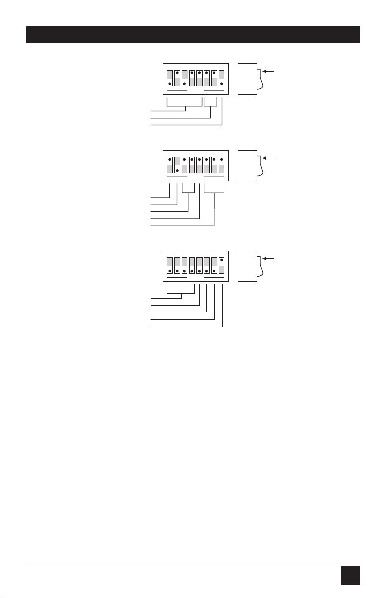
Page 15
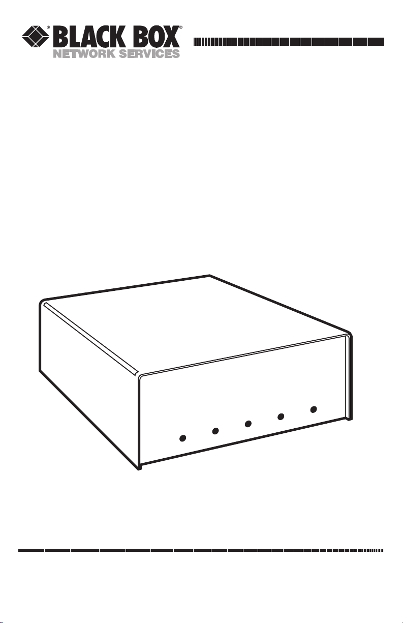
15
Figure 3-1. Factory-Default Settings.
1 2 3 4 567 8
OPEN
SW3
IEEE Addr
IEEE Term
EOI
10
LF
Disabled
Switch
Side
View
DOT
1 2 3 4 5 6 7 8
OPEN
SW2
Mode
Talk-Back on Timeout
Serial Term
C
Enabled
LF
Switch
Side
View
DOT
Echo
Parity
No Echo
No Parity
1 2 3 4 5 6 7 8
OPEN
SW1
Baud Rate
Handshake
Word Length
9600
RTS/CTS
8 Data Bits
Switch
Side
View
DOT
Talk-Back on Term
Enabled
Stop Bits
2 Stop Bits
CHAPTER 3: Getting Started
Page 16

16
RS-232↔IEEE 488 INTERFACE CONVERTER
Note that the interface converter comes configured as an IEEE controller. In
this mode, the interface converter is designed to allow an RS-232 computer to
communicate with an IEEE peripheral such as a plotter. This controller mode
is described in detail in Chapter 4.
The interface converter may also be configured as an IEEE peripheral. As an
IEEE peripheral, it allows an IEEE controller to communicate with an RS-232
device. The peripheral mode of operation is described in detail in Chapter 5.
To modify any of these defaults, follow this simple procedure:
1. Disconnect the power supply from the AC line and from the interface. Also
disconnect any IEEE or serial cables.
WARNING
Never open the interface converter’s case while it is connected to the AC
line. Failure to observe this warning may result in equipment failure,
personal injury, or death.
2. Place the interface converter upside down on a flat surface. Remove the
four screws located near the rubber feet.
3. Return the interface converter to the upright position and carefully remove
the top cover.
4. Change whichever DIP-switch settings you need to change.
5. When you have made all your changes, reverse this procedure to
reassemble the interface converter.
3.3 Serial Port Settings
The first parameters to configure are those that correspond to the RS-232
port. These include baud rate, word length, number of stop bits, parity
selection and type of RS-232 handshake. Each of these are described in
the following sections.
3.3.1 S
ERIALBAUDRATE
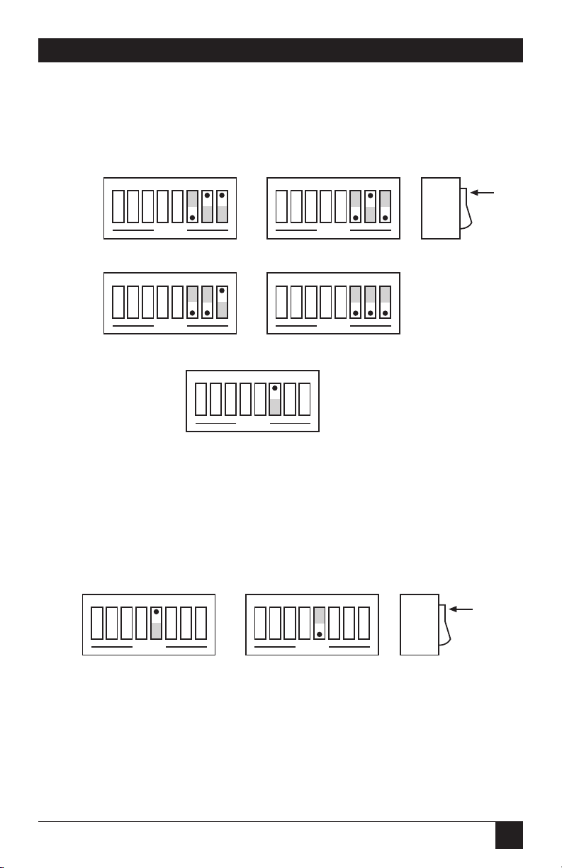
The “baud rate” is the number of serial data bits per second transferred into
and out of the RS-232 interface. SW1-1 through SW1-4 determine the serial
baud rate. The factory-default baud rate is 9600 baud. Baud rates may be
selected from 110 to 57,600 baud. Refer to the following diagram for specific
baud rates.
Page 17
17
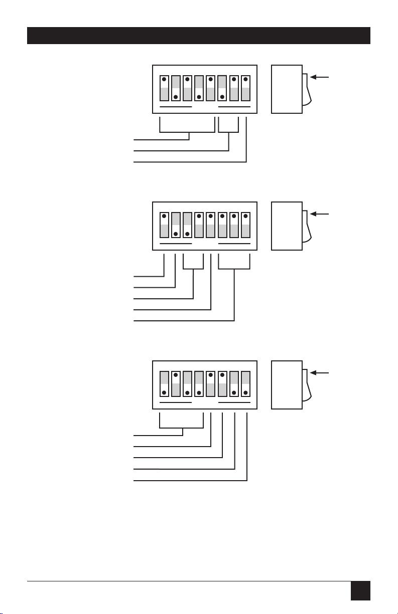
CHAPTER 3: Getting Started
Figure 3-2. Switch SW1: Selecting the Serial Baud Rate.
Switch
Side
View
DOT
110
1 2 3 4 567 8
OPEN
1 2 3 4 567 8
OPEN
1800
300
1 2 3 4 567 8
OPEN
110
1 2 3 4 567 8
OPEN
1 2 3 4 567 8
OPEN
2400
110
1 2 3 4 567 8
OPEN
1 2 3 4 567 8
OPEN
3600
1 2 3 4 567 8
OPEN
4800135
1 2 3 4 567 8
OPEN
1 2 3 4 567 8
OPEN
720015 0
1 2 3 4 567 8
OPEN
1 2 3 4 567 8
OPEN
9600
600
1 2 3 4 567 8
OPEN
1 2 3 4 567 8
OPEN
19,200
1200
1 2 3 4 567 8
OPEN
1 2 3 4 567 8
OPEN
57,600
Page 18
18
RS-232↔IEEE 488 INTERFACE CONVERTER
3.3.2 S
ERIALWORDLENGTH(DATABITS
)
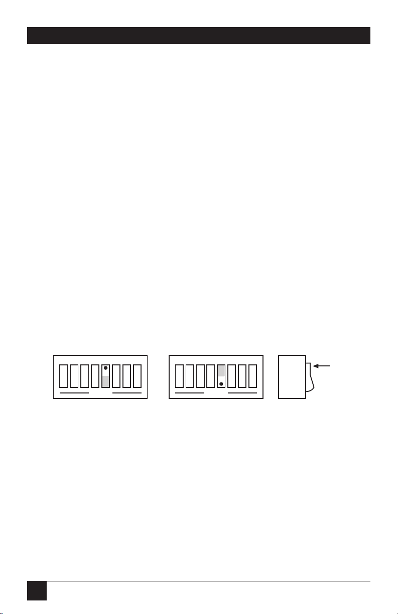
SW1-6 determines the number of data bits, often referred to as word length,
for each serial character transmitted or received. The factory default is 8 data
bits.
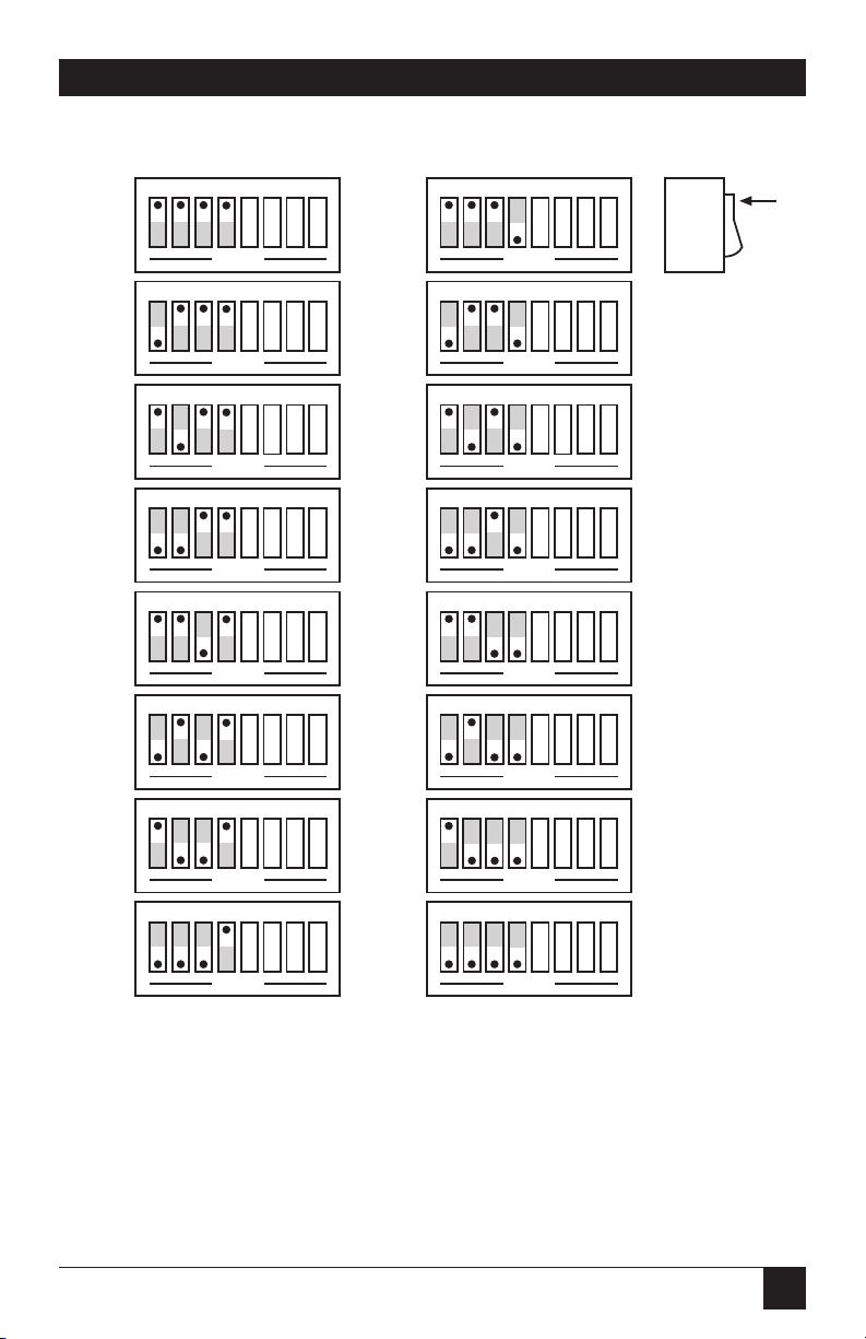
Figure 3-3. Switch SW1: Selecting the Serial Word Length (Data Bits).
3.3.3 S
ERIALSTOPBITS
Switch SW1-8 determines the number of stop bits contained in each serial
character transmitted and received. The factory default is 2 stop bits.
Figure 3-4. Switch SW1: Selecting the Serial Stop Bits.
Switch
Side
View
DOT
1 2 3 4 567 8
OPEN
2 Stop Bits
1 2 3 4 567 8
OPEN
1 Stop Bit
1 2 3 4 567 8
OPEN
8 Data Bits
1 2 3 4 567 8
OPEN
7 Data Bits
Switch
Side
View
DOT
Page 19
19
3.3.4 S
ERIALPARITY
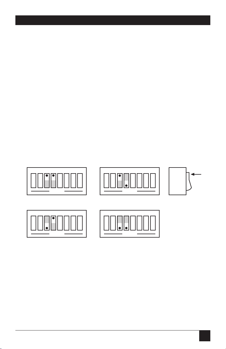
Serial Parity is selected with S2-6 through S2-8. The interface converter
generates the selected parity during serial transmissions but it does not
check parity on data that is received. The factory default is parity disabled.
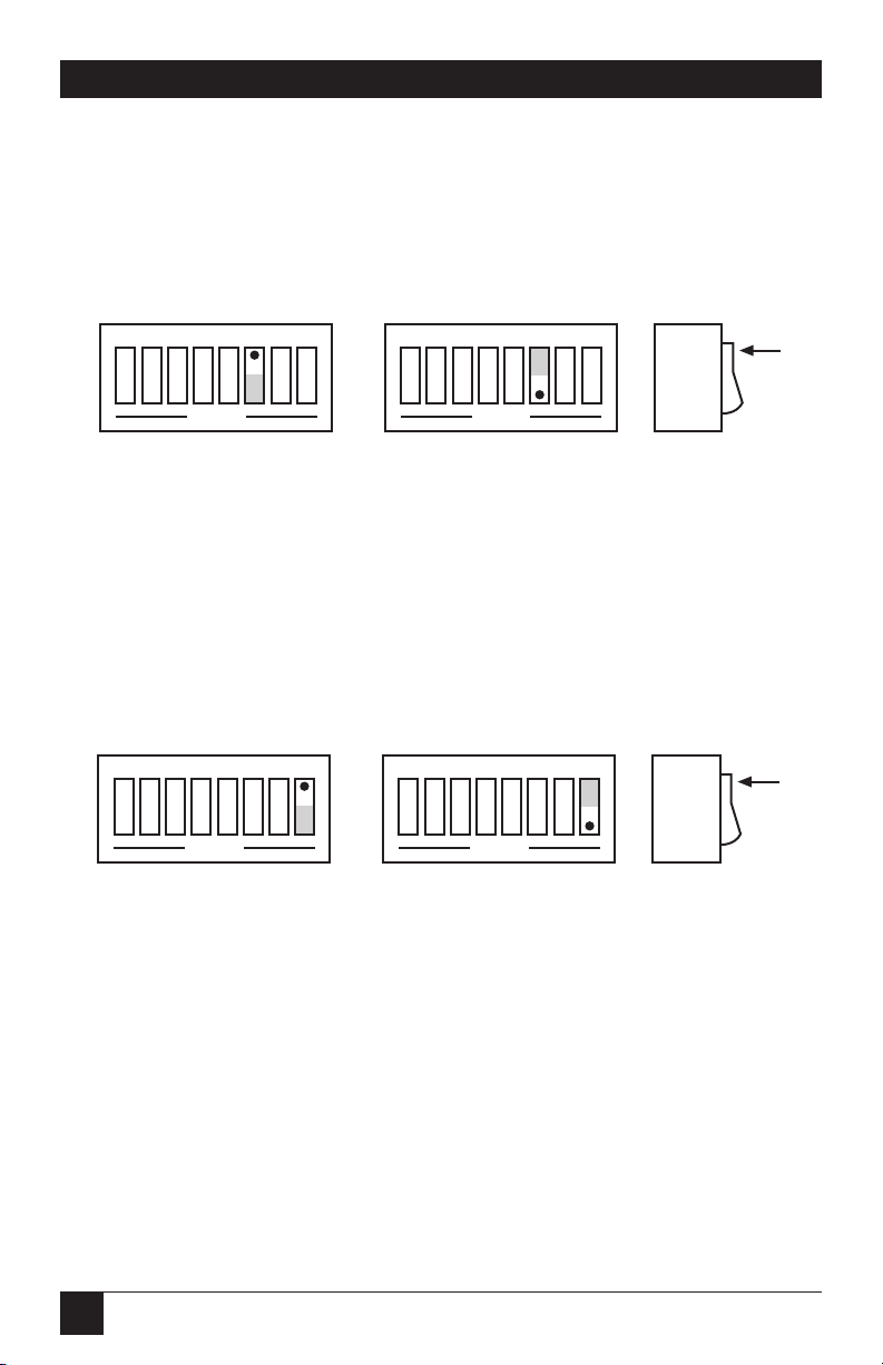
Figure 3-5. Switch SW2: Selecting the Serial Parity.
3.3.5 S
ERIALECHO
Serial data sent to the interface converter will be echoed back to the serial
host if SW2-5 is set to the open position. The factory default is Echo Disabled.
Figure 3-6. Switch SW2: Enabling or Disabling Echo.
1 2 3 4 567 8
OPEN
Echo Disabled
1 2 3 4 567 8
OPEN
Echo Enabled
Switch
Side
View
DOT
Switch
Side
View
DOT
1 2 3 4 567 8
OPEN
Mark Parity
1 2 3 4 567 8
OPEN
Odd Parity
1 2 3 4 567 8
OPEN
Space Parity
1 2 3 4 567 8
OPEN
Even Parity
1 2 3 4 567 8
OPEN
Parity Disabled
CHAPTER 3: Getting Started
Page 20
20
RS-232↔IEEE 488 INTERFACE CONVERTER
3.3.6 S
ERIALHANDSHAKE
Switch SW1-5 is used to select hardware [RTS/CTS] or software [Xon/Xoff]
serial handshake control.
With X-ON/X-OFF, the interface converter issues an X-OFF character [ASCII
value of $13] when its buffer memory is near full. When the X-OFF character
is sent, there are still more than 1000 character locations remaining to protect
against buffer overrun. When it is able to accept more information, the interface converter issues an Xon character [ASCII value of $11]. The interface
converter also accepts X-ON/X-OFF on transmit from the serial host it is
communicating with. RTS/CTS serial control becomes inactive when XON/X-OFF is enabled. The RTS output is, however, set to an active high
state. The CTS input is not used for this handshake and may be left
floating (unconnected).
With RTS/CTS, the interface converter un-asserts RTS (sets RTS low) when
its buffer memory is near full. When RTS is un-asserted, there are still more
than 1000 character locations remaining to protect against buffer overrun.
When it is able to accept more information, the interface converter asserts
RTS (sets RTS high). The interface converter will not transmit data to the
serial host if it detects the CTS input un-asserted (low) when configured
for this hardware handshake.
The factory-default serial control is hardware, RTS/CTS.
Figure 3-7. Switch SW1: Selecting the Serial Handshake.
Switch
Side
View
DOT
1 2 3 4 567 8
OPEN
RTS/CTS
1 2 3 4 567 8
OPEN
X-ON/X-OFF
Page 21
21
CHAPTER 3: Getting Started
3.4 Selecting Terminator Substitution
The interface converter can be configured to provide RS-232-to-IEEE-488 and
IEEE-488-to-RS-232 terminator substitution. This is useful when interfacing an
RS-232 device which only issues carriage return [CR] as an output terminator
to an IEEE controller which expects a carriage return followed by a line feed
[CR-LF].
In a case like that, the serial terminator should be selected for CR Only while
the IEEE terminator is set to CR-LF. When a serial CR character is received,
it is discarded, and an IEEE CR-LF is substituted for it. In the IEEE-to-RS-232
direction, the IEEE CR is unconditionally discarded. Upon receipt of the
IEEE LF, a serial CR is substituted.
The interface converter can be made totally data transparent by setting both
the serial and IEEE terminators to be CR Only or LF Only.
3.4.1 S
ERIALTERMINATOR
SW2-3 and SW2-4 select the serial terminators for the serial input and output.
The factory default is LF Only.
Figure 3-8. Switch SW2: Selecting the Serial Terminator.
Switch
Side
View
DOT
CR Only
1 2 3 4 567 8
OPEN
LF-CR
1 2 3 4 567 8
OPEN
1 2 3 4 567 8
OPEN
LF Only
1 2 3 4 567 8
OPEN
CR-LF
Page 22
22
RS-232↔IEEE 488 INTERFACE CONVERTER
3.4.2 IEEE BUST
ERMINATOR
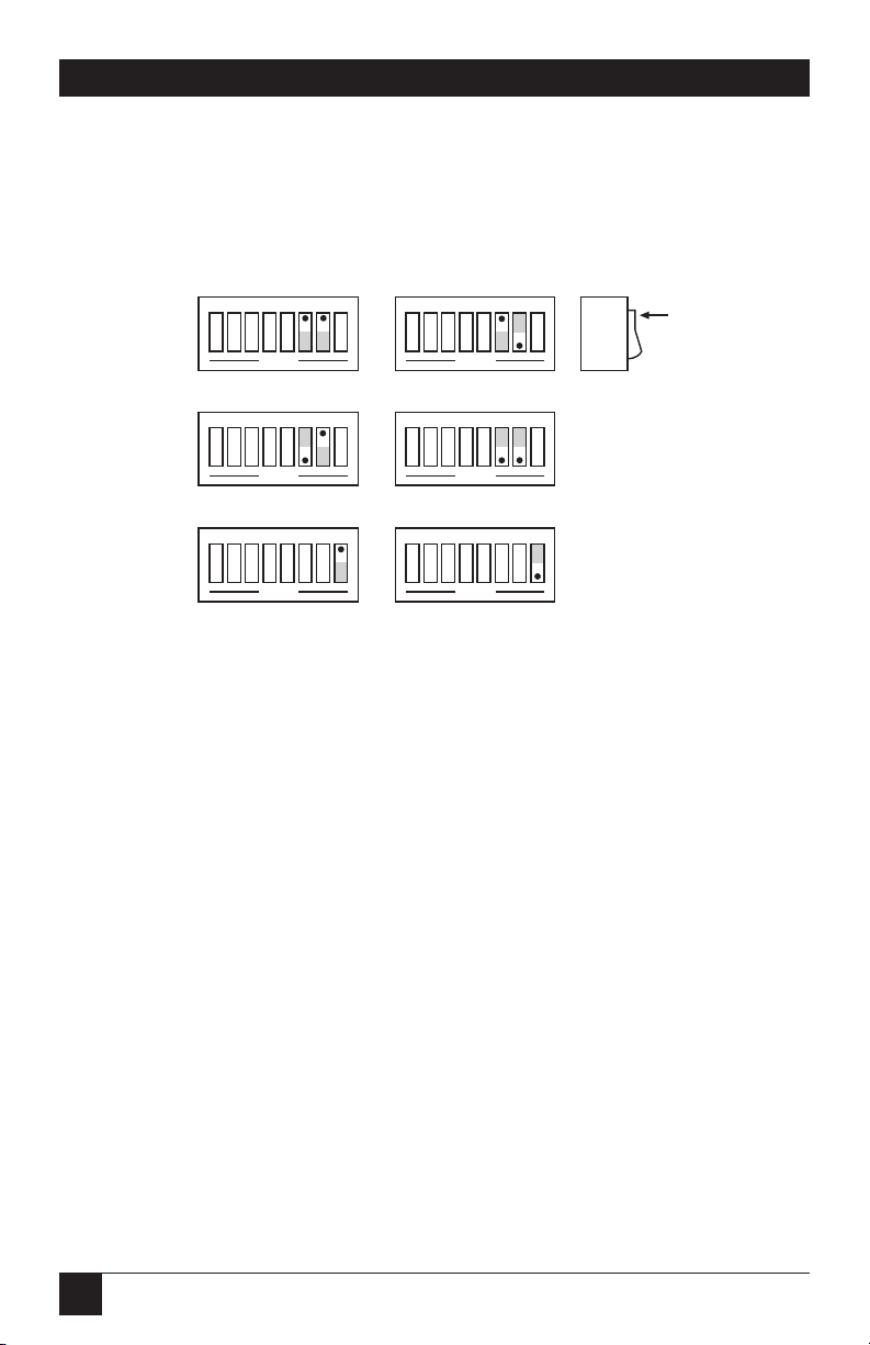
SW3-6 through SW3-8 set the IEEE bus terminators used for data sent or
received by the interface converter. EOI, a line used to signal the end of
a multiple character bus transfer, may also be enabled. If enabled, EOI
is asserted when the last selected bus terminator is sent. Factory default
is LF Only with EOI disabled.
Figure 3-9. Switch SW3: Selecting the IEEE Bus Terminator.
3.5 Selecting the Mode
SW2-1 sets the major operating mode of the interface converter. The IEEE
Controller (RS-232-to-IEEE converter) mode allows a serial host device to
send data to a single IEEE bus peripheral. Applications include interfacing
a listen-only or addressable IEEE printer/plotter to a serial printer port.
Refer to Chapter 4 for more detailed information on the controller mode
of operation.
The Peripheral mode is used when interfacing a serial device to an IEEE
controller. Data which is sent by the IEEE controller to the interface
converter is transmitted out its serial port. Data received from the serial
device is buffered by the interface converter until read by the IEEE controller.
Refer to Chapter 5 for more detailed information on the peripheral mode
of operation.
The factory default is the IEEE Controller mode, an RS-232-to-IEEE
converter.
Switch
Side
View
DOT
1 2 3 4 567 8
OPEN
LF Only
1 2 3 4 567 8
OPEN
CR-LF
1 2 3 4 567 8
OPEN
CR Only
1 2 3 4 567 8
OPEN
LF-CR
1 2 3 4 567 8
OPEN
EOI Disabled
1 2 3 4 567 8
OPEN
EOI Enabled
Page 23

23
CHAPTER 3: Getting Started
Figure 3-10. Switch SW2: Selecting the Mode.
3.6 Selecting the IEEE Address
SW3-1 through SW3-5 select the IEEE bus address of the interface converter
when in the IEEE Peripheral mode. These same switches are used in the IEEE
Controller mode to select the address of the device that will be controlled.
[Refer to Chapters 5 and 4 respectively for additional information]. The
address is selected by simple binary weighting, with SW3-1 being the least
significant bit and SW3-5 the most significant. The factory default is address 10.
Listen Only is a special type of Peripheral operation. In the Listen Only mode
the interface converter accepts all data transmitted on the bus, ignoring any
bus addressing, and transfers it out its serial port. The interface converter is
set to Listen Only mode by setting its address to 31. If the IEEE address is set
to 31 in the peripheral mode, it is adjusted to 30.
Figure 3-11. Switch SW3: Selecting the IEEE Address.
Switch
Side
View
DOT
1 2 3 4 567 8
OPEN
0
1
0 x 16
1 x 8
0 x 4
1 x 2
0 x 1
-0
-8
-0
-2
+ -0
IEEE Address = 10
Switch
Side
View
DOT
1 2 3 4 567 8
OPEN
Peripheral Mode
1 2 3 4 567 8
OPEN
Controller Mode
Page 24

24
RS-232↔IEEE 488 INTERFACE CONVERTER
3.7 Feature Selections
The functions of the remaining switches are dependent on the mode
selected. A brief description of each of these features follows. You should
refer to the listed sections for additional information.
3.7.1 C
ONTROLLERFEATURES
In the IEEE Controller (RS-232-to-IEEE 488 Converter) mode, SW1-7 is
used to determine whether the interface should, after sending the IEEE
bus terminators, address the attached bus device to talk. The factory default
is Talk-Back On Terminator enabled.
SW2-2 selects whether the interface converter should address the attached bus
device to talk when the interface converter has nothing more to send to that
device. The factory default is Talk-Back On Timeout enabled.
Refer to Chapter 4 for complete details on these features.
Figure 3-12. Switch SW1: Enabling or Disabling “Talk Back
on Terminator” in Controller Mode.
Figure 3-13. Switch SW2: Enabling or Disabling “Talk Back
on Timeout” in Controller Mode.
Switch
Side
View
DOT
1 2 3 4 567 8
OPEN
Talk-Back on
Timeout Disabled
1 2 3 4 567 8
OPEN
Talk-Back on
Timeout Enabled
Switch
Side
View
DOT
1 2 3 4 567 8
OPEN
Talk-Back on
Terminator Disabled
1 2 3 4 567 8
OPEN
Talk-Back on
Terminator Enabled
Page 25

25
CHAPTER 3: Getting Started
3.7.2 P
ERIPHERALFEATURES
In the IEEE Peripheral (IEEE 488 to RS-232 converter) mode, SW1-7 enables
the interface to assert the SRQ IEEE bus interface line to indicate that it has
received the last switch selected serial terminator character from the serial
device.
Figure 3-14. Switch SW1: Enabling or Disabling SRQ on Last Serial
Terminator in Peripheral Mode.
3.8 Serial Interface
The interface converter has the ability to output signal levels that are
compatible with either RS-232 or RS-422. An internal DIP shorting plug
determines which electrical specification is chosen. If the interface is to be
connected to an IBM®PC or compatible, the RS-232 level should be selected.
If it will be connected to a Macintosh®, the RS-422 level should be used. For
connection to other computers, refer to the manufacturer’s manual to
determine which levels are supported.
Switch
Side
View
DOT
1 2 3 4 567 8
OPEN
SRQ on Last
Terminator Disabled
1 2 3 4 567 8
OPEN
SRQ on Last
Terminator Enabled
Page 26
26
RS-232↔IEEE 488 INTERFACE CONVERTER
3.8.1 RS-232/RS-422 S
IGNALLEVELSELECTION
The interface converter’s factory default signal levels are compatible with
RS-232. To select RS-422 levels, carefully remove the 8-position shorting plug
with a small flat blade screwdriver from J106. Install the DIP jumper into J205
making certain that all of the pins on the shorting plug are inserted correctly.
Figure 3-15. Selecting RS-232 or RS-422 Signal Levels.
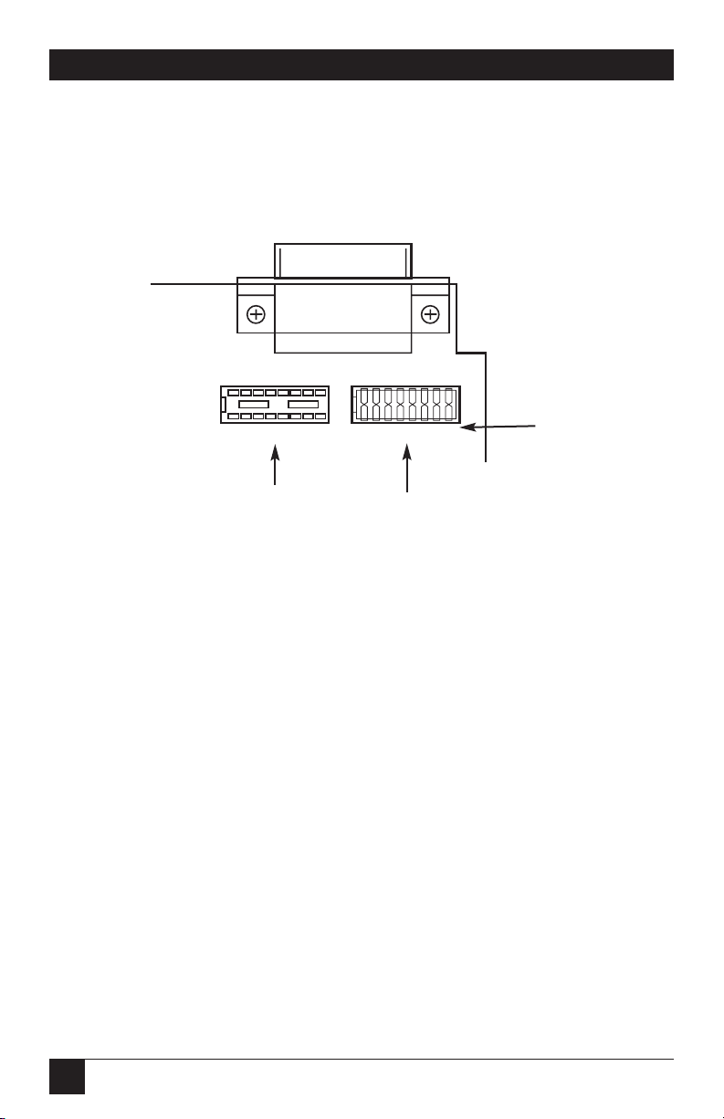
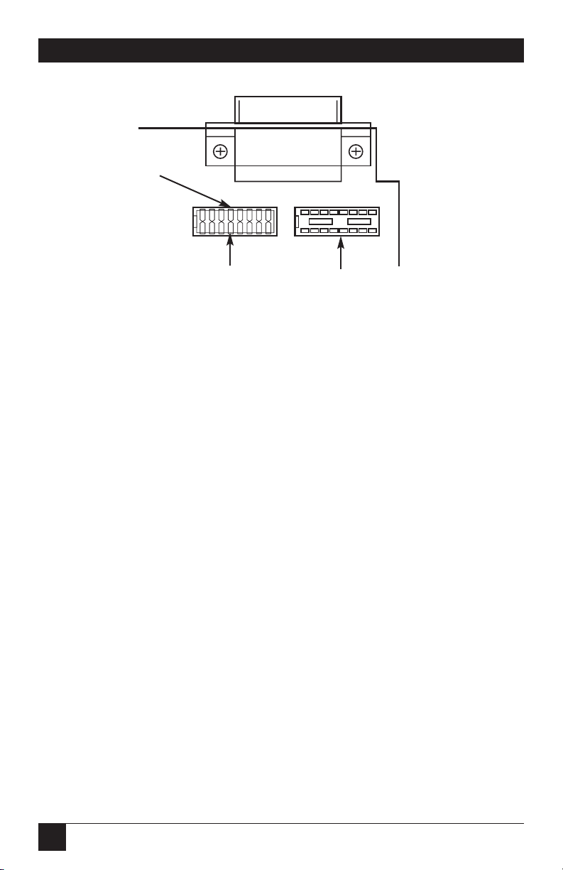
3.8.2 S
ERIALSIGNALDESCRIPTIONS
The interface converter is equipped with a standard DB25 female connector
on its rear panel and requires a standard DB25 male mating connector. The
interface converter’s connector is configured as DCE type equipment for
RS-232 communications, which means the interface converter always transmits data on Pin 3 and receives the data on Pin 2. The following lists and
describes the RS-232 and RS-422 signals provided on the interface converter.
Shorting Plug
RS-232
RS-422
Page 27

27
CHAPTER 3: Getting Started
Figure 3-16. Rear View of the Interface Converter’s Serial Connector.
-RxD Receive Data—Input—Pin 2
This pin accepts serial data sent by the RS-232 or RS-422 host. The serial
data is expected with the word length, baud rate, stop bits, and parity
selected by the internal switches. The signal level is low true.
-TxD Transmit Data—Output—Pin 3
This pin transmits serial data to the RS-232 or RS-422 host. The serial data
is sent with the word length, baud rate, stop bits, and parity selected by the
internal switches. The signal level is low true.
CTS Clear To Send—Input—Pin 4
The CTS input is used as a hardware-handshake line to prevent the
interface converter from transmitting serial data when the RS-232 host
is not ready to accept it. When RTS/CTS handshake is selected on the
internal switches, the interface converter will not transmit data out -TxD
while this line is un-asserted (lowered). If the RS-232 host is not capable
of driving this line it can be connected to the Vtest output (Pin 6) of the
interface converter. If X-ON/X-OFF handshake is selected, the CTS line
is not tested to determine if it can transmit data.
RTS Request To Send—Output—Pin 5
The RTS output is used as a hardware handshake line to prevent the
RS-232/RS-422 host from transmitting serial data if the interface converter
is not ready to accept it. When RTS/CTS handshake is selected on the
internal switches, the interface converter will drive the RTS output high
when there are more than 1,000 character locations available in its
internal buffer. If the number of available locations drops to less than
1,000, the interface converter will unassert (lower) this output. If
Xon/Xoff handshake is selected, the RTS line will be permanently
driven active (high).
13 1
25 14
-RXD
-TXD
CTS
RTS
+VTEST
GND
+VTEST
+RXD
+TXD
Page 28

28
RS-232↔IEEE 488 INTERFACE CONVERTER
Vtest Test Voltage—Output—Pin 6
This pin is connected to +5 volts through a 1K resistor. It is also common
to Vtest on Pin 9.
Gnd Ground—Pin 7
This pin sets the ground reference point for the other RS-232 inputs and
outputs.
Vtest Test Voltage—Output—Pin 9
This pin is connected to +5 volts through a 1K resistor. It is also common
to Vtest on Pin 6.
+RxD Receive Data Plus—Input—Pin 14
This pin accepts serial data sent by the RS-422 host. The serial data is
expected with the word length, baud rate, stop bits, and parity selected by
the internal switches. The signal level is high true and only connected to
this pin when RS-422 operation is selected. It is 180 degrees out of phase
with -RxD.
+TxD Transmit Data Plus—Output—Pin 16
This pin transmits serial data to the RS-422 host. The serial data is sent
with the word length, baud rate, stop bits, and parity selected by the
internal switches. The signal level is high true and only connected to
this pin when RS-422 operation is selected. It is 180 degrees out of phase
with -TxD.
Page 29
29
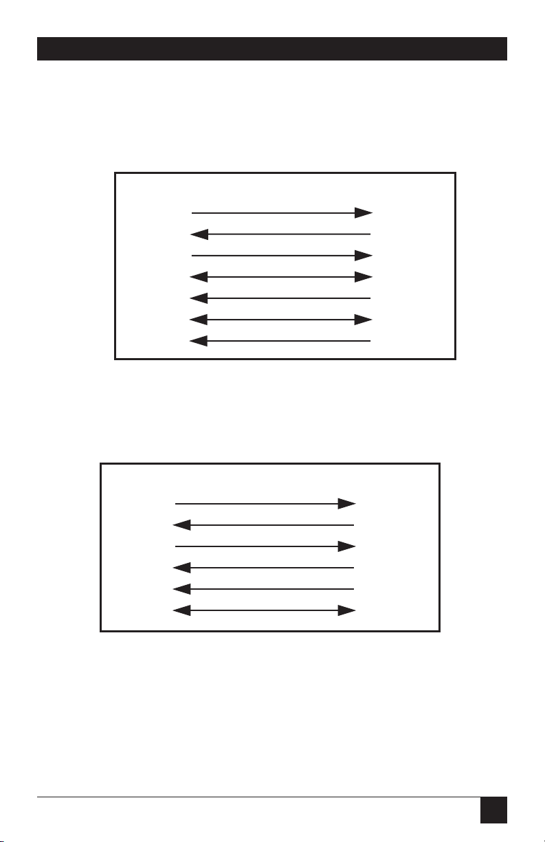
3.8.3 S
ERIAL-CABLEWIRINGDIAGRAMS
If a cable was not purchased with the interface, the following diagrams will be
helpful in making your own cable. Simple soldering skills and an attention to
detail will ensure successful construction.
Figure 3-17. Wiring Diagram:
Macintosh to Interface Converter (RS-422).
Figure 3-18. Wiring Diagram: IBM PC or Compatible with
DB25 Serial Connector to Interface Converter (RS-232).
-TxD 2 2 -RxD
-RxD 3 3 -TxD
RTS 4 4 CTS
CTS 5 5 RTS
DSR 6 3 V test
Gnd 7
7 Gnd
DB25 Female DB25 Male
Mini DINs Male DB25 Male
RTS 1
CTS 2
-TxD 3
Gnd 4
-RxD 5
+TxD 6
+RxD 8
4 CTS
5 RTS
2 -RxD
7 Gnd
3 -TxD
14 +RxD
16 +TxD
CHAPTER 3: Getting Started
Page 30
30
RS-232↔IEEE 488 INTERFACE CONVERTER
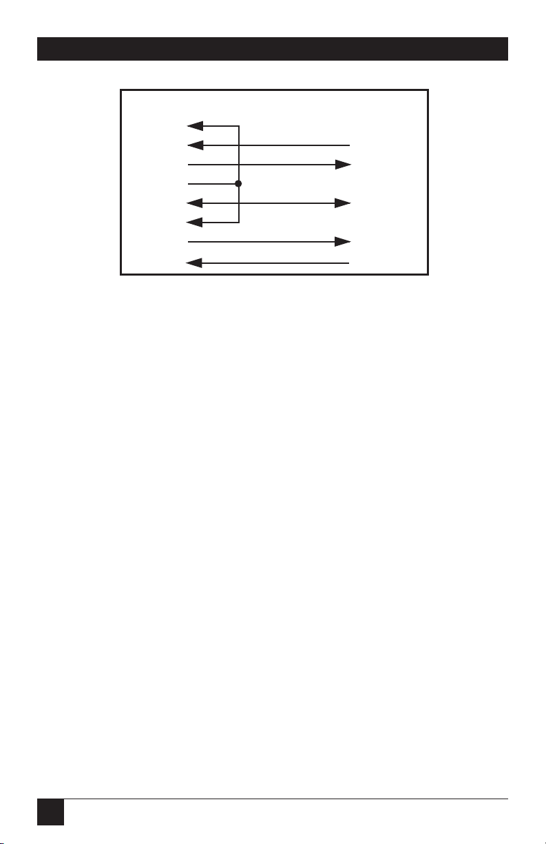
Figure 3-19. Wiring Diagram: IBM AT or Compatible with DB9 Serial
Connector to Interface Converter (RS-232).
NOTE
Standard AT 9-pin-to-25-pin adapter cables are not wired as shown
above and will not work with the interface converter.
3.9 General
Refer to the following sections for specific operational modes. This subsection gives a general test of functionality. After setting the power-on defaults
and reassembling the interface converter, plug the power-supply connector
into the rear jack on the interface.
CAUTION
Never plug the power supply into the interface while it is connected to
AC line power. If you do, you could damage the interface converter.
WARNING
The power supply provided with the interface converter is intended for
INDOOR USE ONLY. Using it outdoors could result in equipment failure,
personal injury, or death.
DCD 1
-RxD 2 3 -TxD
-TxD 3 2 -RxD
DTR 4
Gnd 5 7 Gnd
DSR 6
RTS 7 4 CTS
DB9 Female DB25 Male
CTS 8 5 RTS
Page 31

31
After plugging the power-supply connector into the interface, plug the power
supply into AC line power. Turn the rear-panel power switch ON (the “1”
position). All the front-panel indicators should light momentarily while the
interface converter performs an internal ROM and RAM self-check. At the
end of this self-check, all indicators except POWER should turn off.
If there is an error in the ROM checksum, all of the LEDs will remain on.
Flashing LEDs indicate a RAM failure. Should such an error occur, turn the
rear-panel switch to the OFF [0] position and retry the above procedure.
If the front-panel indicators do not flash and the POWER indicator does not
remain lit, there may not be any power supplied to the interface. In this event,
check the AC line and the rear-panel connection of the power supply. If the
problem is unresolved, call your supplier.
If proper operation is obtained, connect an interface cable to the DB25 port
on the rear of the interface converter. Connect the other end to the host’s
serial port. Except for connecting IEEE bus instruments, the interface
converter is installed and ready to use.
WARNING
The interface converter makes its earth-ground connection through the
serial interface cable. It should only be connected to the IEEE host.
Failure to do so may allow the interface converter to float to a bus-device
test voltage. This could result in damage to the interface, personal injury,
or death.
CHAPTER 3: Getting Started
Page 32

32
RS-232↔IEEE 488 INTERFACE CONVERTER
4.1 Controller-Mode (Serial to IEEE) Operation
The IEEE Controller mode allows a serial RS-232 or RS-422 host device to
send data to a single IEEE bus peripheral or to multiple peripherals if they
occupy the same bus address. Applications include interfacing a listen-only
or addressable IEEE printer/plotter to a serial printer port.
Once the interface converter has initialized itself after power-on, it waits for
serial input data. When received, it addresses the selected IEEE device to
listen with the following bus sequence:
ATNUNL,MTA,LAG,*ATN
The data received from the serial host is placed into a circular serial input
buffer. Simultaneously, characters are removed from that buffer and sent
to the IEEE bus device. The serial terminator(s), if present, are not sent.
Instead, the IEEE terminators are substituted and sent in their place.
As long as the serial input buffer is not empty, the interface converter will
continue to send data from it to the IEEE bus device. If the serial input buffer
becomes emptied, the interface converter will command the IEEE bus device
to talk if one of the talk-back features is enabled. This allows the interface
converter to be used as a controller with devices, such as plotters or
instruments, that return status and other information to the host computer.
When the interface converter addresses the IEEE bus device to talk it uses the
following bus sequence:
ATNUNL,MLA,TAG,*ATN
The interface converter then accepts data from the IEEE device and returns
it to the host until the last selected IEEE terminator is detected. The IEEE bus
terminators are replaced by the serial terminators, and these are then sent to
the serial host.
If the IEEE device has been addressed to talk but does not respond or finish
transmission by the time additional characters are received in the circular
serial-input buffer, the talk sequence will be aborted to allow additional
serial information to be sent to the IEEE device.
4. Controller Operation
Page 33

33
CHAPTER 4: Controller Operation
4.2 Serial and IEEE Terminator Substitution
The interface converter can be configured to provide serial-to-IEEE-488 and
IEEE-488-to-serial terminator substitution. This is useful when interfacing a
serial host which only issues carriage return [CR] as an output terminator to
an IEEE peripheral which expects a carriage return followed by a line feed
[CR-LF].
In this case, the serial terminator should be selected for CR Only while the
IEEE terminator is set for CR-LF. When a serial CR character is received, it is
discarded and replaced with an IEEE CR followed by an IEEE LF. In the IEEE
to serial direction, the IEEE CR is unconditionally discarded. Upon receipt of
the IEEE LF a serial CR is substituted.
The interface converter can be made totally data-transparent by setting both
the serial and IEEE terminators to be CR Only or LF Only. Refer to Chapter 3
for the proper switch settings for both the IEEE and serial terminators.
Page 34

34
RS-232↔IEEE 488 INTERFACE CONVERTER
4.3 IEEE Address Selection
SW3-1 through SW3-5 select the IEEE bus address of the IEEE peripheral
the interface converter will be communicating with. These switches set the
address of the IEEE device that will be controlled, not the address of the
interface converter. The address of the interface converter is automatically
adjusted so that address conflicts will not occur. The address is selected by
simple binary weighting with SW3-1 being the least significant bit and SW3-5
the most significant. If address 31 (reserved on the IEEE bus) is selected
in the controller mode, address 30 is assigned as the device it will be
communicating with. The following figure shows the IEEE address
selection of 10.
Figure 4-1. Switch SW3: Selecting the IEEE Address.
4.4 Talk-Back Features
Two different switch-selectable talk-back features are included to provide bidirectional communication with the IEEE device. Whether either talk-back
feature should be enabled depends on the application.
4.4.1 T
ALK-BACK ONTERMINATOR
SW1-7 is used to determine whether the interface should address the attached
bus device to talk after sending the selected IEEE bus terminator(s). This
feature is commonly used to provide bidirectional communication with a
single IEEE instrument. Talk-back will only occur if there is no serial data to
output to the IEEE device. The factory default is Talk-Back On Terminator
enabled.
Switch
Side
View
DOT
1 2 3 4 567 8
OPEN
0
1
0 x 16
1 x 8
0 x 4
1 x 2
0 x 1
-0
-8
-0
-2
+ -0
IEEE Address = 10
Page 35

35
Figure 4-2. Switch SW1: Enabling or Disabling
“Talk-Back on Terminator.”
When the serial input buffer becomes empty, the interface converter checks
the last characters sent to the IEEE bus device. If these were the IEEE bus
terminators and Talk-Back on Terminator is enabled, the IEEE bus device is
addressed to talk. Any data received by the interface converter from the bus
device is sent to the serial host.
When the last IEEE bus terminator is detected from the IEEE device, the
interface converter disables the device from sending additional information
by asserting Attention (ATN) on the bus.
If the IEEE device does not responded or finish transmission by the time
additional characters are received into the serial input buffer, the talk
sequence will be aborted to allow additional serial information to be sent to
the IEEE device.
The program example on the next page shows how this feature can be used to
communicate with a single IEEE instrument. The program example is written
in BASIC on an IBM PC or compatible and communicates with a Keithley
Model 196 DMM.
10 '
20 ' Example Program using interface converter with
25 ' the Talk-Back on Terminator feature enabled to
30 ' communicate with a Keithley Model 196 DMM
40 '
50 ' Open BASIC’s serial communications port
60 OPEN "COM1: 9600, N, 8, 2" AS 1
70 ' Set the Model 196 DMM to the 30VDC range
80 PRINT #1, "F0R3X"; ' The ; suppresses terminators
90 ' Request 10 Readings from 196”
100 FOR N=1 to 10
110 PRINT #1," " ' Output terminator
120 LINE INPUT #1, A$ ' Get reading from 196
130 PRINT A$ ' print it on the screen
140 NEXT N
150 END
Switch
Side
View
DOT
OPEN
Talk-Back on
Terminator Disabled
1 2 3 4 5 6 7 8
OPEN
Talk-Back on
Terminator Enabled
1 2 3 4 5 6 7 8
CHAPTER 4: Controller Operation
Page 36

36
RS-232↔IEEE 488 INTERFACE CONVERTER
4.4.2 T
ALK-BACK ONTIMEOUT
SW2-2 selects whether the interface converter should address the attached
bus device to talk when the interface converter has no more serial data to
send. This feature relies on time and not on terminators. Its use is primarily
for simulating a serial plotter from an IEEE 488 (HP-IB) plotter. The factory
default is Talk-Back On Timeout enabled.
Figure 4-3. Switch SW2: Enabling or Disabling
“
Talk-Back on Timeout.”
If Talk-Back on Timeout is enabled, the interface converter waits
approximately 100 milliseconds after it detects that its serial input buffer is
empty. If no serial character has been received by the end of this time, the
IEEE bus device is addressed to talk. The choice of talk-back modes depends
strongly on the type of device and software being used. For most plotter
applications, the Talk-Back on Timeout feature should be enabled.
When the last IEEE bus terminator is detected from the IEEE device, the
interface converter disables the device from sending additional information
by asserting Attention (ATN) on the bus. If the IEEE device does not respond
or finish transmission by the time additional characters are received into the
serial input buffer, the talk sequence will be aborted to allow additional serial
information to be sent to the IEEE device.
Most IEEE 488 plotters will not respond to the talk address sequence with
output data unless there has been a specific device dependent command
sent to tell them what to say. If they have not been told what to say, they
say nothing.
Switch
Side
View
DOT
1 2 3 4 567 8
OPEN
Talk-Back on
Timeout Disabled
1 2 3 4 567 8
OPEN
Talk-Back on
Timeout Enabled
Page 37

37
CHAPTER 4: Controller Operation
The following is an example of how this feature can be used to communicate
with an IEEE plotter. The program example is written in BASIC on an IBM
PC or compatible. It turns the PC into a dumb serial terminal. When a key
is pressed on the keyboard, the character is transmitted out of the serial
(COM1) port. Any serial data which is received from the port is printed
on the display.
10 ' Dumb Terminal Program for the interface converter
20 ' This program allows direct interaction between
30 ' the IBM PC and an IEEE plotter through the
40 ' interface converter. The interface converter must have Talk-Back
50 ' on Timeout enabled.
60 'Open the serial communications port
70 OPEN "COM1: 9600,n,8,2,cs,ds" AS 1
80 ' Display any data received from the COM1 port
90 IF LOC(1) THEN PRINT INPUT$(LOC(1),1);: GOTO 90
100 ' Transmit key presses to the COM1 port and screen
110 K$=INKEY$
120 PRINT #1, K$; : PRINT K$;
130 GOTO 90 ' Do it again
Enter the program into the computer and run it. The example below shows
how to test the interface converter’s operation with a Hewlett-Packard®7470A
plotter. Other IEEE plotters are similar, but you should refer to the plotter’s
programming manual for the proper command syntax. Notice the interface
converter’s front-panel LEDs as you type the plotter commands.
Type the following HP-GL®output-identify command on the keyboard...
OI;
The plotter (HP®7470A) should immediately respond with.....
7470A
When you type the following HP-GL command on the keyboard, the plotter
should respond by retrieving its pen, drawing a line and returning the pen.
SP1;PA1000,1000;PD;PA1000,6000;PU;SP0;
Page 38

38
RS-232↔IEEE 488 INTERFACE CONVERTER
4.5 Plotter Applications
To use the interface converter to interface an HP-IB plotter to a serial
computer port, you will need the following information about your system:
1) The serial data format that the application (plotting or graphics)
program expects the plotter to communicate with. These parameters
include baud rate, word length, stop bits, parity and serial control.
Some programs allow these parameters to be selected by the user. Other
graphics programs depend on the RS-232 version of the plotter defaults.
Usually, Hewlett-Packard plotters use 9600 baud, 7 data bits, 1 stop bit,
even parity, and X-ON/X-OFF serial control. Since these plotters are
available with serial interfaces, the operator’s manual of your IEEE
plotter should contain this information.
2) The IEEE bus address of your plotter. This address is usually set by a DIP
switch located on the rear of the plotter. The first five switches set the
address, which, for Hewlett-Packard plotters, is usually address 5. Refer
to the plotter’s operator’s manual for exact information.
Set the interface converter’s internal DIP switches to match the parameters
determined above. Other parameters which should be selected include:
1. Talk-Back on Terminator Enabled.
2. Talk-Back on Timeout Enabled.
3. Serial Terminators set to CR Only.
4. IEEE Terminators set to CR Only with EOI enabled.
Page 39
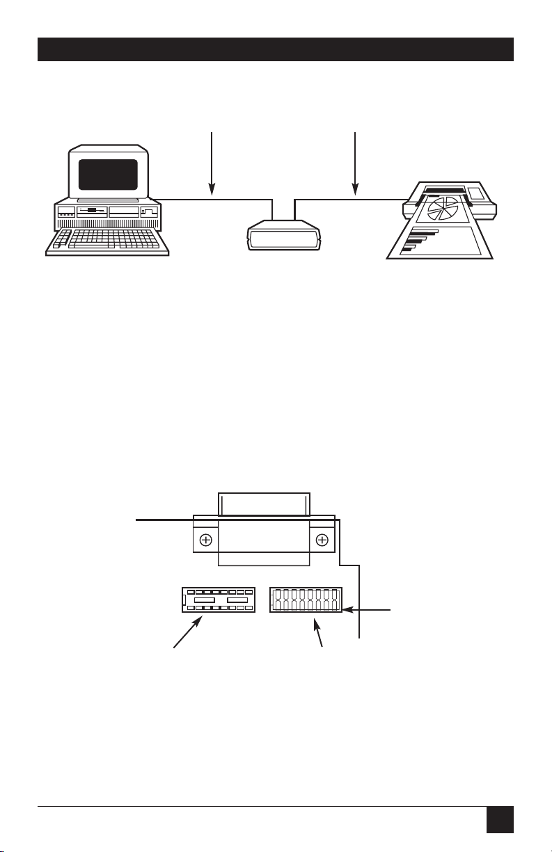
39
Figure 4-4. A PC-Based Graphics System.
The following shows the interface converter’s internal switch settings required
to use a Hewlett-Packard 7580A plotter with AutoCAD®from AUTODESK on
an IBM PC or compatible. Because PCs and compatibles output RS-232 levels,
the shorting DIP jumper should be set to the RS-232 position (J206).
Figure 4-5. Selecting RS-232 Signal Levels.
CHAPTER 4: Controller Operation
IEEE 488
Shorting Plug
RS-422
RS-232
RS-232
Interface
Converter
Page 40

40
RS-232↔IEEE 488 INTERFACE CONVERTER
Figure 4-6. Interface Converter Settings for Use with HP 7580A Plotter
on an IBM PC.
When using the interface converter with plotting programs on the Macintosh
computer with graphic drivers such as MacPlot®, some serial data format
parameters are user-modifiable. The following is a partial MacPlot configuration screen which allows selection of baud rate, stop bits, and parity. With
this driver, the word length is fixed to 7 data bits with X-ON/X-OFF serial
control. These non-modifiable defaults are plotter dependent. Refer
to the plotter or driver manual for the defaults of the specific plotter.
For this example, 57600 baud with one stop bit and no parity has been
chosen for the serial data format.
1 2 3 4 567 8
OPEN
SW2
Mode
Talk-Back on Timeout
Serial Term
C
Enabled
CR
Switch
Side
View
DOT
Echo
Parity
No Echo
Even
1 2 3 4 567 8
OPEN
SW3
IEEE Addr
IEEE Term
EOI
5
CR Only
Enabled
Switch
Side
View
DOT
Switch
Side
View
DOT
1 2 3 4 5 6 7 8
OPEN
SW1
Baud Rate
Handshake
Word Length
9600
X-ON/X-OFF
7 Data Bits
Talk-Back on Terminator
Enabled
Stop Bits
1 Stop Bit
Page 41

41
Figure 4-7. MacPlot Configuration Screen.
Figure 4-8. A Macintosh Based Graphics System.
The Macintosh computer outputs RS-422 levels. Because of this, the internal
DIP shorting jumper is set to the RS-422 position (J205).
Baud Rate:
57600
Paper SiStop Bits:
1
Parity:
None
Settings for HP 7500A
Apple Plotter
Calcomp 104x/7x,9x5
Calcomp 81
Colorwriter 6200DS10
Colorwriter 6310
Colorwriter 6320
Epson HI-80
Facit 4551
Graphtec FP5301
Graphic MP31 / 2 / 300
H.P. 7220
H.P. 7440A ColorPro
H.P. 7470A
H.P. 7475
H.P. 7550A
H.P. 7570A DraftPro
H.P. 7580B
H.P. 7585B
Houst
Houst
Houst
Houst
Houst
Houst
Houst
Houst
Houst
File Edit Windows
CHAPTER 4: Controller Operation
Interface
Converter
IEEE 488
RS-422
Page 42
42
RS-232↔IEEE 488 INTERFACE CONVERTER
Figure 4-9. Setting the Internal DIP Shorting Jumper for RS-422.
The following illustrates the interface converter’s internal switch settings
for use with MacPlot, using the previously described format.
RS-422
RS-232
Shorting Plug
Page 43
43
Figure 4-10. Interface Converter Settings for Use with HP 7580A
Plotter on a Macintosh.
After configuration, turn on the plotter and the interface converter. The
interface converter’s front-panel LEDs should all light momentarily while it
performs an internal ROM and RAM test. All LEDs should go out except for
the Power and Talk LED. The Talk LED indicates that the interface converter
has detected the plotter on the IEEE bus and has addressed it to listen.
When the serial host begins to send the interface converter data, the Receive
LED will flash. If it does not, this indicates that the interface is not receiving
data from the serial host. Verify the cables are connected properly and the
serial cable wiring. Verify the serial data format, word length, stop bits and
parity.
1 2 3 4 567 8
OPEN
SW2
Mode
Talk-Back on Timeout
Serial Term
C
Enabled
CR
Switch
Side
View
DOT
Echo
Parity
No Echo
No Parity
1 2 3 4 567 8
OPEN
SW3
IEEE Addr
IEEE Term
EOI
5
CR
Enabled
Switch
Side
View
DOT
Switch
Side
View
DOT
1 2 3 4 5 6 7 8
OPEN
SW1
Baud Rate
Handshake
Word Length
57600
X-ON/X-OFF
7 Data Bits
Talk-Back on Terminator
Enabled
Stop Bits
1 Stop Bit
CHAPTER 4: Controller Operation
Page 44

44
RS-232↔IEEE 488 INTERFACE CONVERTER
4.6 Printer Applications
Most of the information given for plotter applications applies to applications
for interfacing IEEE 488 printers to a serial host. Some high-end printers have
a secondary command setting which must be disabled for the interface
converter to control them. The interface converter does not use secondary
commands to control IEEE peripherals, such as printers or plotters. Refer to
the printer’s instruction manual if there is a question as to whether the
printer requires secondary commands.
Page 45

45
CHAPTER 5: Peripheral Operation
5.1 Peripheral-Mode Operation
This mode of operation is useful in interfacing a serial device, such as a serial
printer, plotter or instrument, to an IEEE controller. Data which is sent by the
IEEE controller to the interface converter is buffered and transmitted out its
serial port. Data received from the serial device is buffered by the interface
converter until read by the IEEE controller. The interface converter can
buffer approximately 32,000 bytes of data from both the IEEE input and the
serial input.
The interface converter will refuse to accept more data from the IEEE
controller when its buffer memory is full. It does this by preventing
completion of the bus handshaking sequences. It will also request that
additional serial data not be sent by negating its Request To Send (RTS)
output or by transmitting the X-OFF ASCII character. The serial handshake
used depends on the handshake selection (see Chapter 3).
5.2 Serial and IEEE Input Buffers
Memory in the interface converter is dynamically allocated for the serial input
and IEEE input buffers. This allows for the most efficient partitioning of
memory for any given application.
At power on, or device clear, each buffer is allocated a 128-byte mini-buffer
or queue. When the serial input (or IEEE input) requires more buffer space,
additional queues are allocated. When a queue is empty, it is released from
the input buffers so that it may be re-allocated wherever it is required.
There are approximately 250 available queues for a total of 32,000 bytes of
buffer (character) space. Queues are continually allocated and released as
required by the serial and IEEE input. Of the 250 available queues, 240 are
issued without regard to controlling the receipt of additional serial or IEEE
input data.
When the serial input buffer requests one of the last 10 queues (in other
words, when there are 1280 character locations left), it signals the serial host
that it should stop sending data. This is accomplished by either unasserting
RTS or issuing “X-OFF,” depending on which serial handshake control has
been switch selected.
5. Peripheral Operation
Page 46

46
RS-232↔IEEE 488 INTERFACE CONVERTER
When more than 10 queues become available, it asserts RTS or issues “X-ON.”
The IEEE bus input signals that the IEEE input (or serial output) buffer is full
when the number of queues available drops below 10 (1280 character
locations left). When the number of available queues drops to 4 or less (512
character locations left), the IEEE interface of the interface converter stops
accepting data from the bus. This bus hold-off will only occur until additional
queues (more than 4) become available. Then the interface will resume
accepting bus data.
5.3 IEEE Data Transfers
The following methods may be used by the IEEE controller when sending
data to the interface converter:
5.3.1 B
LINDBUSDATATRANSFERS
If the IEEE controller does not mind waiting an indefinite time for data space
in the buffer to become available, the data can simply be sent to the interface
converter. This is referred to as “blind data transfer,” because the IEEE
controller is blind as to whether or not the interface converter is capable
of accepting data. In this case, the bus controller’s output data transfer will
be held off by the interface converter if it is unable to buffer the data. It will
resume accepting IEEE input data when memory becomes available. This
type of control might be appropriate in a single-user environment.
To illustrate how this would appear, let’s assume the interface converter is
connected to a serial device which will accept data at 1200 baud or 110 bytes
per second. The IEEE bus controller is capable of sending data to the
interface converter at a rate of 5000 bytes per second. The data would be
transferred on the bus at 5000 characters per second for slightly over six
seconds, filling over 31,000 locations. At that time, the IEEE input would
hold off additional data transfers until 128 characters are sent out the serial
port at rate of 110 characters per second. This 110 cps would then become
the average bus data acceptance rate of the interface converter.
If the controller is set to detect a data time-out error, then it will do so if the
interface converter holds off IEEE input data transfers for too long. The error
can be used to alert the operator to the problem, such as a printer out of
paper, so that it can be corrected. If the controller then restarts transmission
exactly where it left off, no data will be lost.
If data is requested by the controller and no serial input data is available in
the interface converter, the bus will hang until serial data is received. If no
serial data is received, it will hang forever until the controller times out.
Page 47

47
CHAPTER 5: Peripheral Operation
5.3.2 C
ONTROLLEDBUSDATATRANSFERS
If the controller must avoid waiting for the serial device, it can “serial-poll” the
interface converter. Serial polling is a method by which the controller can
inquire the internal status of the interface without disturbing any data being
transferred, slowing data transfers, or locking up the bus. You should refer to
the programming manual of your controller to determine the method of
performing serial polls.
When serial-polled, the interface converter provides eight bits of status
information to the controller. The most significant bit (DIO8) of the
interface converter’s serial poll byte is set to a logic “1” when the IEEE input
buffer is NOT EMPTY. The term NOT EMPTY is used to signify that not all
of the previous data sent to the interface has been transmitted to the serial
device. If it is NOT EMPTY, the controller may avoid sending any more data
to the interface converter. If this bit is a logic “0,” then the serial device has
accepted all previous data and the IEEE controller may send more.
Another bit (DIO4) of the Serial Poll byte is used to indicate additional
information concerning the IEEE input buffer. This bit is set to a logic “1”
when there is 1280 or less locations in the buffer for data. It is cleared, set
to a logic “0”, when there is greater than 1280 locations available. This bit is
referred to as the IEEE input buffer FULL bit.
When serial data is received, DIO5 of the Serial Poll byte is set to “1”, to
indicate to the IEEE controller that the serial input buffer is NOT EMPTY. If
this bit is set, it indicates that at least one character is available in the serial
input buffer to be read by the IEEE controller. Once all of the serial input
data is read by the IEEE controller this bit is reset.
The interface converter can generate a request for service on the bus when it
receives the last serial terminator. To enable this feature, the Peripheral SRQ
switch, located on the internal switch bank of SW1, must be enabled. When
SRQ is enabled, the interface converter will assert the IEEE bus SRQ line and
set serial poll status bits DIO7 and DIO3 when the last serial terminator is
detected. The IEEE controller must perform a serial poll on the interface to
clear the SRQ. If the Peripheral SRQ switch is in the disabled position, there
will not be any indication in the serial-poll status byte that a serial terminator
has been received.
Page 48
48
RS-232↔IEEE 488 INTERFACE CONVERTER
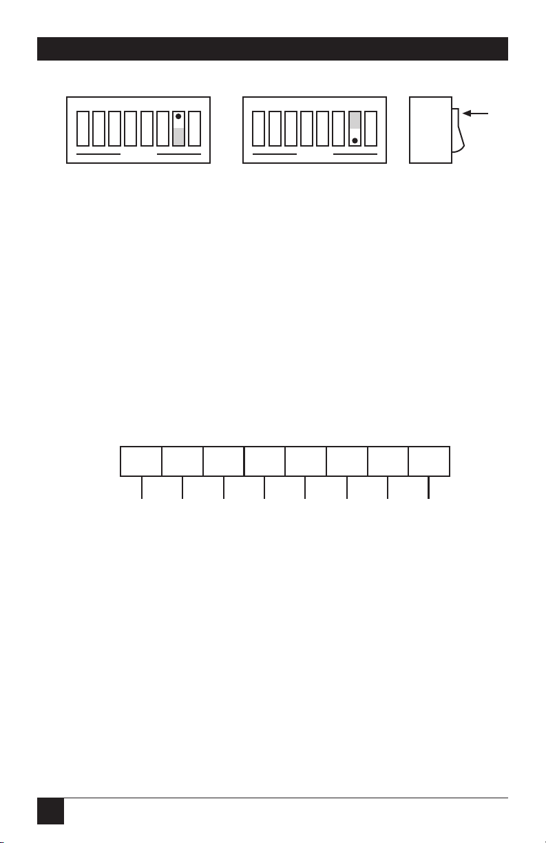
Figure 5-1. Switch SW1: Enabling or Disabling
“SRQ on Last Terminator.”
5.4 Serial-Poll Status-Byte Register
The following shows and describes the serial-poll status information provided
by the interface converter.
DIO8 IEEE Input Buffer NOT Empty
This bit is set when the IEEE input buffer contains one
or more data bytes.
Figure 5-2. Serial Poll Status Byte.
DIO8 DIO7 DIO6 DIO5 DIO4 DIO3 DIO2 DIO1
128 64 32 16 8 4 2 1
IEEE Input Buffer Not Empty
Request Service—rsv bit
Not Used—Always "0"
Serial Input Buffer Not Empty
IEEE Input Buffer Full
Last Serial Input Terminator
Serial Handshake
Not Used—Always "0"
Switch
Side
View
DOT
1 2 3 4 567 8
OPEN
SRQ on Last
Terminator Enabled
1 2 3 4 567 8
OPEN
SRQ on Last
Terminator Disabled
Page 49

49
CHAPTER 5: Peripheral Operation
DIO7 rsv
serial-poll status information
This bit is defined by the IEEE 488 Specification and is used
to indicate to the bus controller that the interface converter is
the bus device that requested service. It is cleared when the
interface is serial polled by the controller.
DIO6 Not Defined—Always “0”
DIO5 Serial Input Buffer NOT EMPTY
This bit is set when the serial input buffer contains one or
more data bytes which have not been sent out the IEEE bus.
It is cleared, set to “0,” when the buffer is empty.
DIO4 IEEE Input Buffer Full
When this bit is set, it indicates that the interface converter
may hold off the controller on subsequent data transfers. The
interface may continue to accept an additional 512 characters,
depending on the size of the serial input buffer.
DIO3 Received Last Serial Terminator
If the Peripheral SRQ feature is enabled, the interface
converter will issue a request for service by asserting the SRQ
line and setting this bit along with the rsv bit (DIO7). It is
cleared, along with rsv, when serial polled by the controller.
If this feature is not enabled, this bit is always “0.”
DIO2 Serial Handshake
This bit indicates the present state of the serial handshake.
If it is set to “1,” the serial device connected to the interface
converter is capable of accepting serial data. If “0,” the RTS
line is unasserted, if configured for hardware handshake, or
the “X-OFF” character has been received, if configured for
X-ON/X-OFF software handshake.
DIO1 Not Used—Always “0”
Page 50

50
RS-232↔IEEE 488 INTERFACE CONVERTER
5.5 Use of Serial and Bus Terminators
The interface converter can be configured to provide RS-232-to-IEEE-488 and
IEEE-488-to-RS-232 terminator substitution. This is useful when interfacing a
serial device that only issues carriage return [CR] as an output terminator to
an IEEE controller that expects a carriage return followed by a line feed
[CR-LF].
In this previous example, the serial terminator should be selected for CR
Only while the IEEE terminator is set to CR-LF. When a serial CR character is
received it is discarded and substituted with an IEEE CR followed by an IEEE
LF. In the IEEE to serial direction, the IEEE CR is unconditionally discarded.
Upon receipt of the IEEE LF a serial CR is substituted.
The interface converter can be made totally data-transparent by setting both
the serial and IEEE terminators to be CR Only or LF Only. The choice of
appropriate terminators may be determined by inspection of the serial device
and IEEE controller’s instruction manuals. See Chapter 3 of this manual for
instructions on selecting the interface converter’s serial and bus terminals.
5.6 IEEE 488 Bus Implementation
The interface converter implements many of the capabilities defined by the
IEEE 488 1978 specification. These are discussed in the following sections.
The interface converter does not support or respond to these bus uniline
and multiline commands:
Remote Enable (REN)
Go to Local (GTL)
Group Execute Trigger (GET)
Local Lockout (LLO)
Take Control (TCT)
Parallel Poll (PP)
Parallel Poll Configure (PPC)
Parallel Poll Unconfigure (PPU)
Parallel Poll Disable (PPD)
Page 51

51
CHAPTER 5: Peripheral Operation
5.6.1 MYT
ALKADDRESS
(MTA)
When the interface converter is addressed to talk, it retrieves data from
the serial input buffer and outputs it to the IEEE 488 bus. It substitutes the
selected IEEE bus terminators for the received serial terminators. The interface converter will continue to output serial input buffer data as long as the
IEEE controller allows.
5.6.2 MYL
ISTENADDRESS
(MLA)
When the interface converter is addressed to listen, it accepts data from the
active talker and outputs this data through the serial interface. It substitutes
the selected serial terminators for the received IEEE bus terminators.
5.6.3 D
EVICECLEAR
(DCL
AND
SDC)
Device Clear resets the interface converter’s IEEE input and serial input
buffers. Any pending data and Service Requests (SRQ), including the
information they convey, are lost.
5.6.4 I
NTERFACECLEAR
(IFC)
IFC places the interface converter in the Talker/Listener Idle State. It clears
any pending requests for service (SRQ). The condition which caused the SRQ
remains unmodified.
5.6.5 S
ERIALPOLLENABLE
(SPE)
When Serial-Poll-Enabled, the interface converter sets itself to respond to a
serial poll with its serial-poll status byte if addressed to talk. When the serialpoll byte is accepted by the controller, any pending SRQs are cleared. The
interface converter will continue to try to output its serial-poll response until
it is “Serial-Poll-Disabled” by the controller.
5.6.6 S
ERIALPOLLDISABLE
(SPD)
Disables the interface converter from responding to serial polls by the
controller.
5.6.7 U
NLISTEN
(UNL)
UNL places the interface converter in the Listener Idle State.
5.6.8 U
NTALK
(UNT)
UNT places the interface converter in the Talker Idle State.
Page 52

52
RS-232↔IEEE 488 INTERFACE CONVERTER
5.7 IEEE Address Selection
SW3-1 through SW3-5 select the IEEE bus address of the interface converter
when in the IEEE Peripheral mode. The address is selected by simple binary
weighting with SW3-1 being the least significant bit and SW3-5 the most
significant. The following figure shows the IEEE address of the interface
converter set to 10.
Figure 5-3. SW3 View for IEEE Address Selection.
Listen Only Mode
Listen Only is a special type of Peripheral operation. In the Listen Only Mode
the interface converter accepts all data transmitted on the bus and transfers it
out its serial port. The interface converter is set to Listen Only mode by
setting its address to 31 (switches SW3-1 through SW3-5 all open).
NOTE
The 232-488 Converter does not support all of these functions. Refer
back to controller mode (Section 4.1) and peripheral mode (Section 5.1)
for more information about operation of this particular device.
Switch
Side
View
DOT
1 2 3 4 567 8
OPEN
0
1
0 x 16
1 x 8
0 x 4
1 x 2
0 x 1
-0
-8
-0
-2
+ -0
IEEE Address = 10
Page 53

53
CHAPTER 6: IEEE 488 Primer
6.1 History
The IEEE 488 bus is an instrumentation-communication bus adopted by the
Institute of Electrical and Electronic Engineers in 1975 and revised in 1978.
The interface converter conforms to this most recent revision, designated
IEEE 488-1978.
Before this standard was adopted most instrumentation manufacturers
offered their own versions of computer interfaces. This placed the burden
of system hardware design on the end user. If your application required the
products of several different manufacturers, then you might need to design
several different hardware and software interfaces.
The popularity of the IEEE 488 interface (sometimes called the General
Purpose Interface Bus or GPIB) is due to the total specification of the
electrical and mechanical interface as well as the data transfer and control
protocols. The use of the IEEE 488 standard has moved the responsibility of
the user from design of the interface to design of the high-level software that
is specific to the measurement application.
6.2 General Structure
The main purpose of the GPIB is to transfer information between two or
more devices. A device can either be an instrument or a computer. Before
any information transfer can take place, it is first necessary to specify which
will do the talking (send data) and which devices will be allowed to listen
(receive data). The decision of who will talk and who will listen usually falls
on the System Controller, which is the Active Controller at power-on.
The System Controller is similar to a committee chairman. On a well-run
committee, only one person may speak at a time and the chairman is
responsible for recognizing members and allowing them to have their say.
On the bus, the device that is recognized to speak is the Active Talker. There
can only be one Talker at a time if the information transferred is to be clearly
understood by all. The act of “giving the floor” to that device is called
Addressing to Talk. If the committee chairman cannot attend the meeting, or
if other matters require his attention, he can appoint an acting chairman to
take control of the proceedings. For the GPIB, this device becomes the Active
Controller.
6. IEEE 488 Primer
Page 54

54
RS-232↔IEEE 488 INTERFACE CONVERTER
At a committee meeting, everyone present usually listens. This is not the case
with the GPIB. The Active Controller selects which devices will listen and
commands all other devices to ignore what is being transmitted. A device is
instructed to listen by being Addressed to Listen. This device is then referred
to as an Active Listener. Devices that are to ignore the data message are
instructed to Unlisten.
The reason some devices are instructed to Unlisten is quite simple. Suppose a
college instructor is presenting the day’s lesson. The students are told to raise
their hands if the instructor has exceeded their ability to keep up while taking
notes. If a hand is raised, the instructor stops his discussion to allow the slower
students the time to catch up. In this way, the instructor is certain that each
and every student receives all the information he is trying to present. Since
there are a lot of students in the classroom, this exchange of information can
be very slow. In fact, the rate of information transfer is no faster than the rate
at which the slowest note-taker can keep up. The instructor, though, may have
a message for one particular student. The instructor tells the rest of the class
to ignore this message (Unlisten) and tells it to that one student at a rate
which he can understand. This information transfer can then happen much
quicker, because it need not wait for the slowest student.
The GPIB transfers information in a similar way. This method of data transfer
is called handshaking. More on this later.
For data transfer on the IEEE 488, the Active Controller must:
a)Unlisten all devices to protect against eavesdroppers.
b)Designate who will talk by addressing a device to talk.
c)Designate all the devices who are to listen by addressing those devices
to listen.
d) Indicate to all devices that the data transfer can take place.
Page 55
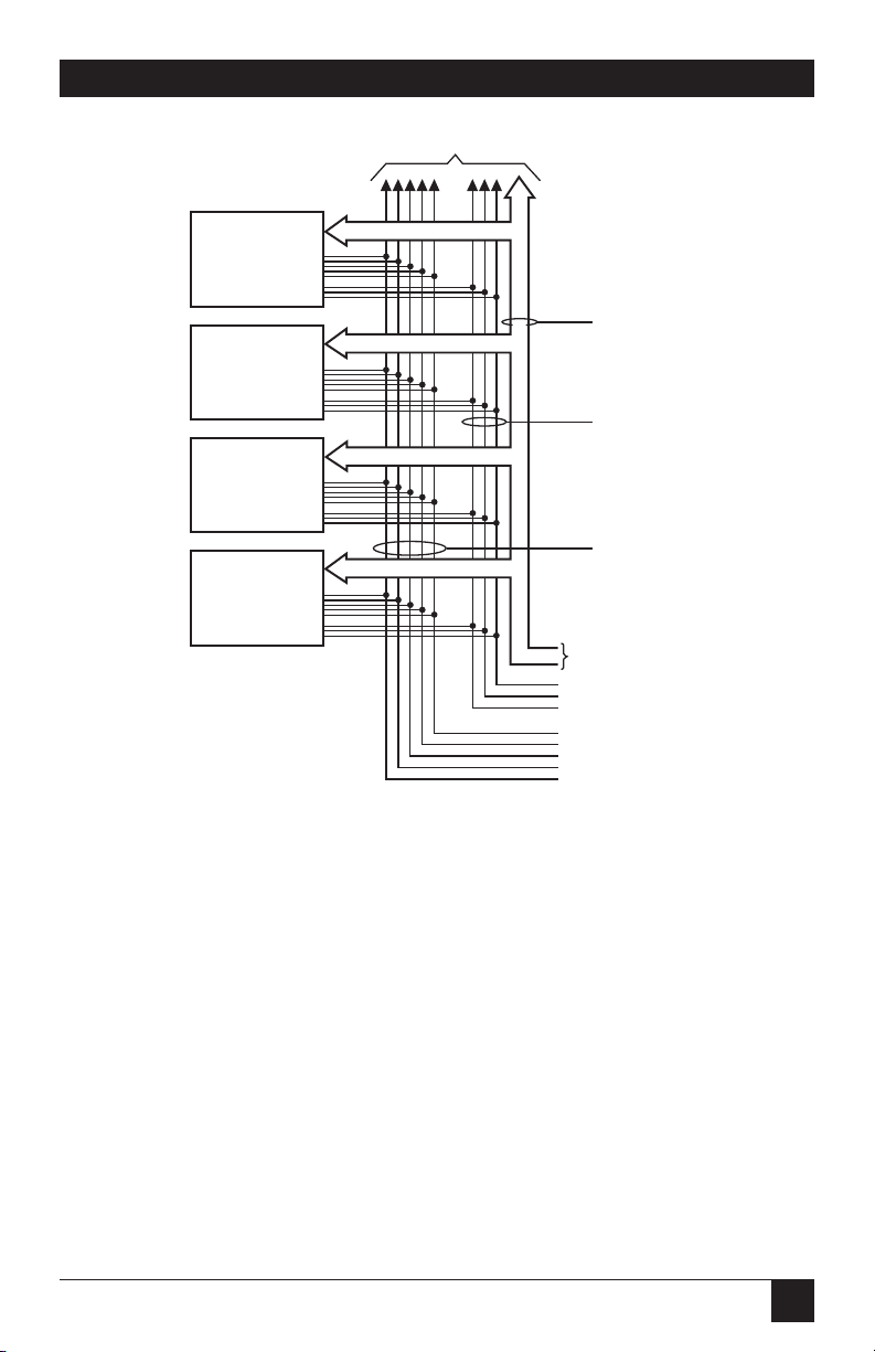
55
CHAPTER 6: IEEE 488 Primer
Figure 6-1. IEEE 488 Bus Structure.
6.3 Send It to My Address
In the previous discussion, the terms “Addressed to Talk” and “Addressed to
Listen” were used. These terms require some clarification.
The IEEE 488 standard permits up to 15 devices to be configured within one
system. Each of these devices must have a unique address to avoid confusion.
In a similar fashion, every building in town has a unique address to prevent
one home from receiving another home’s mail. Exactly how each device’s
address is set is specific to the device’s manufacturer. Some are set by DIP
switches in hardware, others by software. Consult the manufacturer’s
instructions to determine how to set the address.
Addresses are sent with universal (multiline) commands from the Active
Controller. These commands include My Listen Address (MLA), My Talk
Address (MTA), Talk Address Group (TAG), and Listen Address Group
(LAG).
Device 1
System Controller
Able to Talk,
Listen, and Control
Device 2
DMM
Able to Talk
and Listen
Device 3
Printer
Only Able to Listen
Device 4
Frequency Counter
Only Able to Talk
To Other Devices
Data Bus
Data Byte
Transfer
Control
General
Interface
Management
DAV
NRFD
NDAC
IFC
ATN
SRQ
REN
EOI
DIO1-8
Page 56

56
RS-232↔IEEE 488 INTERFACE CONVERTER
6.4 Bus Management Lines
Five hardware lines on the GPIB are used for bus management. Signals on
these lines are often referred to as uniline (single line) commands. The
signals are “active low”: A low voltage represents a logical “1” (asserted),
and a high voltage represents a logical “0” (unasserted).
6.4.1 A
TTENTION
(ATN)
ATN is one of the most important lines for bus management. If Attention is
asserted, then the information contained on the data lines is to be interpreted
as a multiline command. If it is not, then that information is to be interpreted
as data for the Active Listeners. The Active Controller is the only bus device
that has control of this line.
6.4.2 I
NTERFACECLEAR
(IFC)
The IFC line is used only by the System Controller. It is used to place all bus
devices in a known state. Although device configurations vary, the IFC
command usually places the devices in the Talk and Listen Idle states
(neither Active Talker nor Active Listener).
6.4.3 R
EMOTEENABLE
(REN)
When the System Controller sends the REN command, bus devices will
respond to remote operation. Generally, the REN command should be issued
before any bus programming is attempted. Only the System Controller has
control of the Remote Enable line.
6.4.4 ENDORI
DENTIFY
(EOI)
The EOI line is used to signal the last byte of a multibyte data transfer. The
device that is sending the data asserts EOI during the transfer of the last data
byte. The EOI signal is not always necessary, as the end of the data may be
indicated by some special character such as carriage return.
The Active Controller also uses EOI to perform a Parallel Poll by
simultaneously asserting EOI and ATN.
6.4.5 S
ERVICEREQUEST
(SRQ)
When a device desires the immediate attention of the Active Controller it
asserts SRQ. It is then the Controller’s responsibility to determine which
device requested service. This is accomplished with a Serial Poll or a Parallel
Poll.
Page 57

57
6.5 Handshake Lines
The GPIB uses three handshake lines in an “I’m ready—Here’s the data—I’ve
got it” sequence. This handshake protocol assures reliable data transfer, at the
rate determined by the slowest Listener. One line is controlled by the Talker,
while the other two are shared by all Active Listeners. The handshake lines,
like the other IEEE 488 lines, are active low.
6.5.1 D
ATAVALID
(DAV)
The DAV line is controlled by the Talker. The Talker verifies that NDAC is
asserted (active low) which indicates that all Listeners have accepted the
previous data byte transferred. The Talker then outputs data on the bus and
waits until NRFD is unasserted (high) which indicates that all Addressed
Listeners are ready to accept the information. When NRFD and NDAC are
in the proper state, the Talker asserts DAV (active low) to indicate that the
data on the bus is valid.
6.5.2 NOTR
EADYFORDATA
(NRFD)
This line is used by the Listeners to inform the Talker when they are ready to
accept new data. The Talker must wait for each Listener to unassert this line
(high), which they will do at their own rate when they are ready for more
data. This assures that all devices that are to accept the information are ready
to receive it.
6.5.3 NOTD
ATAACCEPTED
(NDAC)
The NDAC line is also controlled by the Listeners. This line indicates to the
Talker that each device addressed to listen has accepted the information.
Each device releases NDAC (high) at its own rate, but the NDAC will not
go high until the slowest Listener has accepted the data byte.
CHAPTER 6: IEEE 488 Primer
Page 58
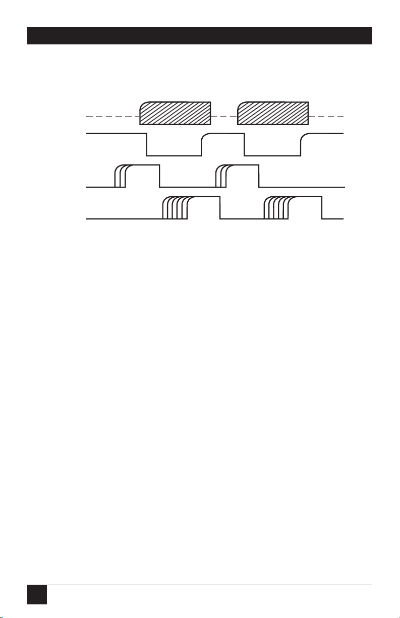
58
RS-232↔IEEE 488 INTERFACE CONVERTER
Figure 6-2. IEEE Bus Handshaking.
6.6 Data Lines
The GPIB provides eight data lines for a bit-parallel/byte-serial data transfer.
These eight data lines use the convention of DIO1 through DIO8 instead of
the binary designation of D0 to D7. The data lines are bidirectional and are
active low.
6.7 Multiline Commands
Multiline (bus) commands are sent by the Active Controller over the data bus
with ATN asserted. These commands include addressing commands for talk,
listen, Untalk, and Unlisten.
6.7.1 GOTOL
OCAL
(GTL)
This command allows the selected devices to be manually controlled. ($01)
6.7.2 L
ISTENADDRESSGROUP
(LAG)
There are 31 (0 to 30) listen addresses associated with this group. The 3 most
significant bits of the data bus are set to 001, while the 5 least significant bits
are the address of the device being told to listen.
1st Data Byte 2nd Data Byte
Valid ValidNot
Valid
Not
Valid
DAV
Source
DIO-8
(composite)
NFRD
Acceptor
NDAC
Acceptor
All
Ready
None
Ready
All
Ready
None
Ready
None
Accept
All
Accept
None
Accept
All
Accept
Page 59

59
CHAPTER 6: IEEE 488 Primer
6.7.3 U
NLISTEN
(UNL)
This command tells all bus devices to Unlisten. The same as Unaddressed to
Listen. ($3F)
6.7.4 T
ALKADDRESSGROUP
(TAG)
There are 31 (0 to 30) talk addresses associated with this group. The 3 most
significant bits of the data bus are set to 010 while the 5 least significant bits
are the address of the device being told to talk.
6.7.5 U
NTALK
(UNT)
This command tells bus devices to Untalk. The same as Unaddressed to Talk.
($5F)
6.7.6 L
OCALLOCKOUT
(LLO)
Issuing the LLO command prevents manual control of the instrument’s
functions. ($11)
6.7.7 D
EVICECLEAR
(DCL)
This command causes all bus devices to be initialized to a predefined or
power-up state. ($14)
6.7.8 S
ELECTEDDEVICECLEAR
(SDC)
This causes a single device to be initialized to a pre-defined or power-up state.
($04)
6.7.9 S
ERIALPOLLDISABLE
(SPD)
The SPD command disables all devices from sending their Serial Poll status
byte. ($l9)
6.7.10 S
ERIALPOLLENABLE
(SPE)
A device which is Addressed to Talk will output its Serial Poll status byte after
SPE is sent and ATN is unasserted. ($18)
6.7.11 G
ROUPEXECUTETRIGGER
(GET)
This command usually signals a group of devices to begin executing a
triggered action. This allows actions of different devices to begin
simultaneously. ($08)
Page 60

60
RS-232↔IEEE 488 INTERFACE CONVERTER
6.7.12 T
AKECONTROL
(TCT)
This command passes bus control responsibilities from the current Controller
to another device which has the ability to control. ($09 )
6.7.13 S
ECONDARYCOMMANDGROUP
(SCG)
These are any one of the 32 possible commands (0 to 31) in this group. They
must immediately follow a talk or listen address. ($60 to $7F)
6.7.14 P
ARALLELPOLLCONFIGURE
(PPC)
For devices capable of performing a Parallel Poll, this command determines
which data bit they are to assert in response to a Parallel Poll ($05)
6.7.15 P
ARALLELPOLLUNCONFIGURE
(PPU)
This disables all devices from responding to a Parallel Poll. ($15)
6.8 More on Service Requests
Most of the commands covered, both uniline and multiline, are the
responsibility of the Active Controller to send and the bus devices to
recognize. Most of these happen routinely by the interface and are totally
transparent to the system programmer. Other commands are used directly by
the user to provide optimum system control. Of the uniline commands, SRQ
is very important to the test system, and the software designer has easy access
to this line by most devices. Service Request is the method by which a bus
device can signal to the Controller that an event has occurred. It is similar to
an interrupt in a microprocessor-based system.
Most intelligent bus peripherals have the ability to assert SRQ. A DMM might
assert it when its measurement is complete, if its input is overloaded or for
any of an assortment of reasons. A power supply might SRQ if its output has
current limited. This is a powerful bus feature that removes the burden from
the System Controller to periodically inquire, “Are you done yet?” Instead, the
Controller says, “Do what I told you to do and let me know when you’re done”
or “Tell me when something is wrong.”
Since SRQ is a single line command, there is no way for the Controller to
determine which device requested the service without additional information.
This information is provided by the multiline commands for Serial Poll and
Parallel Poll.
Page 61

61
6.8.1 S
ERIALPOLL
Suppose the Controller receives a service request. For this example, let’s
assume there are several devices which could assert SRQ. The Controller
issues an SPE (Serial Poll enable) command to each device sequentially. If
any device responds with DIO7 asserted, it indicates to the Controller that it
was the device that asserted, SRQ. Often the other bits will indicate why the
device wanted service. This Serial Polling sequence, and any resulting action,
is under control of the software designer.
6.8.2 P
ARALLEL
P
OLL
The Parallel Poll is another way the Controller can determine which device
requested service. It provides the who but not necessarily the why. When bus
devices are configured for Parallel Poll, they are assigned one bit on the data
bus for their response. By using the Status bit, the logic level of the response
can be programmed to allow logical OR/AND conditions on one data line by
more than one device. When SRQ is asserted, the Controller (under user’s
software) conducts a Parallel Poll. The Controller must then analyze the eight
bits of data received to determine the source of the request. Once the source
is determined, a Serial Poll might be used to determine the why.
Of the two polling types, the Serial Poll is the most popular due to its ability
to determine the who and why. In addition, most devices support Serial Poll
only.
CHAPTER 6: IEEE 488 Primer
Page 62

62
RS-232↔IEEE 488 INTERFACE CONVERTER
7.1 Theory of Operation
The heart of the interface converter is a 6809 microprocessor (U101)
supported by 8K bytes of firmware EPROM [U102 (2764)] and 32K bytes of
static RAM [U103 (58256)]. A Versatile Interface Adapter [U104 (65B22)]
is used to generate real-time interrupts for the firmware operating system.
The front-panel annunciators are also driven by U104 through an inverter
[U113 (74LS04)]. The IEEE 488 bus interface is accomplished by a
TMS9914A [U106] controller with drivers U107 and U108. The serial
interface is provided by the UART [6551 (U105)]. If RS-232 levels are chosen,
they are provided by the RS-232 transceiver (U209). If RS-422 levels are
selected, the differential driver [26LS30 (U207)] and receiver [26LS33
(U208)] are used.
The internal DIP switches [SW1, SW2, and SW3] are read via 74HCT244
tri-state buffers [U201, U202 and U203]. Power is supplied by an external
unregulated 9-volt wallmount supply. Regulation to the required +5 volts is
provided by U206 [7805].
Decoding of the microprocessor address space is accomplished with a
Programmable Logic Array [U110 (16L8)]. The Memory space allocation is:
Address Device Part Number Function
$0000-$7FFF U103 58258 Static RAM
$A000-$A007 U106 9914A IEEE Controller
$A800-$A807 U105 6551 UART
$B000-$B00F U104 65B22 VIA
$B800 U201 74HCT244 SW1 (S201)
$B801 U202 74HCT244 SW2 (S202)
$B802 U203 74HCT244 SW3 (S203)
$E000-$FFFF U102 2764 Programmed EPROM
7. Theory of Operation
and Board Layout
Page 63

63
7.2 Board Layout
Figure 7-1. Component Layout of the
Interface Converter’s Motherboard.
U108
U107
R102
U101
C106 C107C101
U106
Y101
C118
C117
U102
C102
U103
C103
C105
C110
C113
U113
C124
U110
J104
D102
D106
D105
D104
D103
R104
C104
U104
U105
D101
R101
C108
J101
CHAPTER 7: Theory of Operation and Board Layout
Page 64

64
RS-232↔IEEE 488 INTERFACE CONVERTER
Figure 7-2. Component Layout of the
Interface Converter’s Serial I/O board.
S201
SW1
R201 C201
R202 C202
R203 C203
U202 U203
C206
U201
U206
C210
U205
R205
C205
C212
C211
C213
C214
U209
J206
C209
R207
R206
J205
J204
C208
C207
U207 U208
S205
1
14
BLK
RED
+
S202
SW2
S203
SW3
P204
Page 65

65
APPENDIX A: Sample Dumb-Terminal Program
10 REM *** DUMB-TERMINAL PROGRAM FOR THE interface
converter
20 REM *** Running under IBM BASIC
30 REM *** This Program allows direct interaction between the
40 REM *** IBM PC and an IEEE bus device through the interface
converter.
50 REM *** The interface converter must be configured as the
IEEE bus
60 REM *** controller and have Talk-Back on Terminator enabled.
70 REM ***
80 REM ***
90 REM ***
100 CLS
110 ' Open the serial communications port and set the serial parameters
120 OPEN "COM1: 9600,n,8,2,cs,ds" AS 1
130 ' Display any characters received from the COM1 port
140 IF LOC(1) THEN PRINT INPUT$ (LOC(1) ,1);
150 ' Transmit any key presses from keyboard to the COM1 port and to
the screen
160 K$=INKEY$
170 PRINT #1,K$; : PRINT K$;
180 GOTO 140 ' Do it again
Appendix A. Sample Dumb-Terminal
Program
Page 66

66
RS-232↔IEEE 488 INTERFACE CONVERTER
ACG = Addressed Command Group TAG = Talk Address Group
UCG = Universal Command Group SCG = Secondary Command Group
LAG = Listen Address Group
Appendix B. Character Codes and IEEE
Multiline Messages
$00 0
NUL
$01
SOH
GTL
$02 2
STX
$03 3
ETX
$04
EOT
SDC
$05
ENQ
PPC
$06 6
ACK
$07 7
BEL
$08
BS
GET
$09
HT
TCT
$0A 10
LF
$0B 11
VT
$0C 12
FF
$0D 13
CR
$0E 14
SO
$0F 15
SI
ACG
$10 16SP$20
DLE
1
$11
LLO
$12 18"$22
$13 19#$23
4
$14
DCL
5
$15
PPU
$16 22&$26
$17 23'$27
8
$18
SPE
9
$19
SPD
$1A 26*$2A
$1B 27+$2B
$1C 28,$2C
$1D 29-$2D
$1E 30.$2E
$1F 31/$2F
DC1
DC2
DC3
DC4
NAK
SYN
ETB
CAN
EM
SUB
ESC
FS
GS
RS
US
17!$21
20$$24
21%$25
24($28
25)$29
00
01
02
03
04
05
06
07
08
09
10
11
12
13
14
15
320$30
16
331$31
17
342$32
18
353$33
19
364$34
20
375$35
21
386$36
22
397$37
23
408$38
24
419$39
25
42:$3A
26
43;$3B
27
44<$3C
28
45=$3D
29
46>$3E
30
47?$3F
UNL
48@$40
00
49A$41
01
50B$42
02
51C$43
03
52D$44
04
53E$45
05
54F$46
06
55G$47
07
56H$48
08
57I$49
09
58J$4A
10
59K$4B
11
60L$4C
12
61M$4D
13
62N$4E
14
63O$4F
15
64P$50
16
65Q$51
17
66R$52
18
67S$53
19
68T$54
20
69U$55
21
70V$56
22
71W$57
23
72X$58
24
73Y$59
25
74Z$5A
26
75[$5B
27
76\$5C
28
77]$5D
29
78^$5E
30
79_$5F
UNT
80`$60
SCG
81a$61
SCG
82b$62
SCG
83c$63
SCG
84d$64
SCG
85e$65
SCG
86f$66
SCG
87g$67
SCG
88h$68
SCG
89i$69
SCG
90j$6A
SCG
91k$6B
SCG
92l$6C
SCG
93m$6D
SCG
94n$6E
SCG
95o$6F
SCG
UCG LAG TAG SCG
96p$70
SCG
97q$71
SCG
98r$72
SCG
99s$73
SCG
100t$74
SCG
101u$75
SCG
102v$76
SCG
103w$77
SCG
104x$78
SCG
105y$79
SCG
106z$7A
SCG
107{$7B
SCG
108|$7C
SCG
109}$7D
SCG
110~$7E
SCG
111
$7F
SCG
DEL
112
113
114
115
116
117
118
119
120
121
122
123
124
125
126
127
Page 67

67
How To Read the Chart
APPENDIX B: Character Codes and IEEE Multiline Messages
Hexadecimal Decimal
Equivalent Equivalent
ASCII Character
Address or Command
Page 68

68
RS-232↔IEEE 488 INTERFACE CONVERTER
Abbreviations
IEEE 488 .................................13
Active Controller ...........................53
Address Selection
IEEE ........................................34
Applications
Plotter .....................................38
Printer.....................................44
ATN ................................................56
Attention ........................................56
Baud Rate.......................................16
Blind Bus Data Transfers ..............46
Board Layout ...........................63, 64
Bus Management Lines
Attention.................................56
End Or Identify ......................56
Interface Clear........................56
Remote Enable.......................56
Service Request.......................57
CE Compliant
Operating Conditions .....................2
Character Codes ............................66
Clear To Send................................27
Configuration ................................14
Connectors...............................26, 27
Controlled Bus Data Transfers .....47
Controller Features .......................24
Controller Mode Operation .........32
Controller Operation ....................32
Data Lines ......................................58
Data Transfers
Blind Bus.................................46
Controlled Bus .......................47
Data Valid.......................................57
DAV ................................................57
DCL ..........................................51, 59
Device Clear.............................51, 59
DIO1...............................................49
DIO2...............................................49
DIO3...............................................49
Index
DIO4...............................................49
DIO5...............................................49
DIO6...............................................49
DIO7...............................................49
DIO8...............................................48
Echo................................................19
End Or Identify .............................56
EOI22, 56
Factory-Default Settings ..........14, 15
Feature Selections .........................24
Controller ...............................24
Peripheral ...............................25
Features
Talk Back ...........................34-36
General Purpose
Interface Bus..................................53
GET ................................................59
Go To Local ...................................58
GPIB ...............................................53
Ground...........................................28
Group Execute Trigger .................59
GTL ................................................58
Handshake Lines ...........................57
Data Valid ...............................57
Not Data Accepted .................57
Not Ready For Data................57
IEEE 488 Abbreviations.................13
IEEE 488 Bus
Implementation.............................50
IEEE 488 Primer............................53
IEEE Address Selection.....23, 34, 52
IEEE Bus Terminator ....................22
IEEE Controller
Mode ............................16, 22, 23, 32
IEEE Data Transfers ......................46
IEEE Multiline Messages...............66
IEEE Peripheral.............................16
IFC ...........................................51, 56
Input Buffers..................................45
Inspecting the Unit .......................14
Page 69

69
INDEX
Interface Clear.........................51, 56
Interface Converter
Connectors.....................................26
Introduction...................................12
LAG ................................................58
LEDs ...................................31, 37, 43
Listen Address Group....................58
Listen Only...............................23, 52
LLO ................................................59
Local Lockout................................59
MLA................................................51
Mode
Selection .................................22
Modifying Factory Defaults ...........16
MTA................................................51
Multiline Commands.........50, 56, 58
Device Clear............................59
Go To Local............................58
Group Execute Trigger..........59
Listen Address Group ............58
Local Lockout.........................59
Parallel Poll Configure ..........60
Parallel Poll Unconfigure ......60
Secondary Command
Group......................................60
Selected Device Clear ............59
Serial Poll Disable ..................59
Serial Poll Enable ...................59
Take Control ..........................60
Talk Address Group ...............59
Unlisten ..................................59
Untalk .....................................59
My Listen Address..........................51
My Talk Address ............................51
NDAC .............................................57
Not Data Accepted ........................57
Not Ready For Data .......................57
NRFD..............................................57
Operation
Controller ...............................32
General .............................30, 31
Peripheral ...............................45
Theory.....................................62
Package Contents ..........................14
Parallel Poll....................................61
Parallel Poll Configure..................60
Parallel Poll Unconfigure .............60
Peripheral Features .......................25
Peripheral Mode......................22, 23
Peripheral Operation....................45
Plotter Applications.......................38
Polling Types
Parallel ....................................61
Serial .......................................61
POWER Indicator..........................31
PPC60
PPU.................................................60
Printer Applications ......................44
Receive Data...................................27
Receive Data Plus...........................28
Remote Enable ..............................56
REN ................................................56
Request To Send............................28
RS-232 Signals .....................26-28, 39
RS-422 Signals ...........................26-28
RTS/CTS............................20, 27, 28
Sample Program ............................65
SCG.................................................60
SDC...........................................51, 59
Secondary Command Group........60
Selectable Functions......................14
Selected Device Clear....................59
Selecting an IEEE Address............52
Selecting Terminator
Substitution....................................21
Selecting the IEEE Address...........23
Selecting the Mode........................22
Self-Check ......................................31
Send It to My Address ...................55
Serial and IEEE Input Buffers ......45
Serial and IEEE Terminator
Substitution....................................33
Serial Baud Rate ............................16
Serial Echo .....................................19
Serial Handshake...........................19
Serial Interface ..............................25
Page 70

70
RS-232↔IEEE 488 INTERFACE CONVERTER
Serial Parity ....................................18
Serial Poll .......................................61
Serial Poll Disable....................51, 59
Serial Poll Enable ....................51, 59
Serial Port Settings ........................16
Serial Signal Descriptions .............26
Serial Terminator ..........................21
Serial-Poll Status
Information..............................48, 49
Serial-Poll Status-Byte
Register...........................................48
Service Requests ......................57, 60
Shorting Plug.....................25, 26, 42
Signal Level Selection ...................26
SPD51, 59
SPE ...........................................51, 59
Specifications
General ...................................11
IEEE-488 Interface .................10
Serial Interface .......................10
SRQ.................................................57
SW1.............17, 18, 20, 24, 25, 35, 48
SW2................................19, 21-24, 36
SW3.....................................22, 23, 34
System Controller ..........................53
TAG ................................................59
Take Control..................................60
Talk Address Group ......................59
Talk-Back Features ........................34
Talk-Back on Terminator..............35
Talk-Back on Timeout...................36
TCT ................................................60
Terminator Substitution ...............21
Serial and IEEE ......................33
Terminators ...................................50
Test Voltage ...................................28
Theory of Operation .....................62
Transmit Data ................................27
Transmit Data Plus ........................28
Uniline Commands .......................50
UNL..........................................51, 59
Unlisten..............................51, 54, 59
Unpacking......................................14
UNT..........................................51, 59
Untalk.......................................51, 59
Wiring Diagrams............................29
IBM AT with DB9
Connector to Interface
Converter................................30
IBM PC with DB25
Connectors to Interface
Converter................................29
Macintosh to Interface
Converter................................29
X-ON/X-OFF.....................20, 27, 28
Page 71

1000 Pasrk Drive • Lawrence, PA 15055-1018 • 724-746-5500 • Fax 724-746-0746
© Copyright 1998. Black Box Corporation. All rights reserved.
 Loading...