

Page 1
Technische Dokumentation
B & K s.r.o.
Palisády 20, 811 06 Bratislava
Slovak Republic
02/ 544 307 01
[email protected], www.bruel.sk
Technical Documentation
Documentation Technique
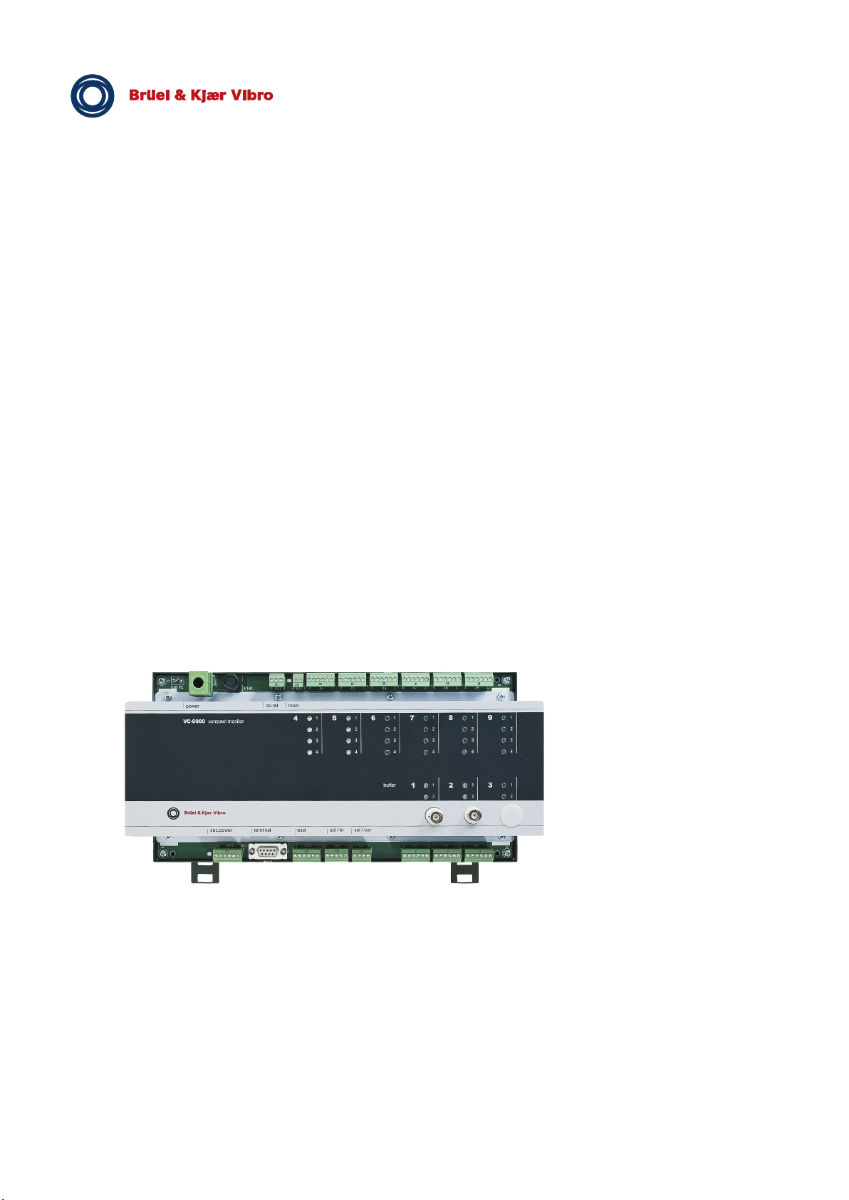
VIBROCONTROL 6000 Compact monitor
Page 2

Page 3

A
B
Individuelle Gerätedokumentation
Individual instrument documentation
Documentation individuelle de l’appareil
Einführung
Introduction
Introduction
Module – Technische Daten
Modules – Technical Data
Modules – Caractéristiques techniques
C
D
Komponenten des Signalflussgraphen
Components of the signal flow chart
Componentes de signaux flux
Dialog mit dem User Terminal
Dialog with the User Terminal
Fenêtre de dialogue Terminal Utilisateur
E
F
Page 4

Page 5

Individuelle Gerätedokumentation
Individual instrument documentation
Documentation individuelle de l’appareil
Inhalt
- Signalflussgraph
- Konfigurationsblatt
- Parametereinstellblatt
- Konfigurationsbeschreibung
- User Terminal Passwort
Content
- Signal flow chart
- Configuration sheet
- Parameter configuration sheet
- Discription of configuration
- User Terminal password
Sommaire
- Signeau de flux
- Fiche de configuration
- Fiche des paramètres
- Description de configuration
- Terminal utilisateur le mot de passe
VC-6000 Compact monitor
Page 6

Page 7

VC-6000TM Compact monitor
User Terminal Superuser Passwort
Passwortgeschützter Menüzugriff
Das Menüsystem zum VC-6000
Passwortschutz ausgestattet. Es gibt zwei Sicherheitsstufen: USER und
SUPERUSER.
Ohne Passworteingabe wird der Benutzer als USER eingeordnet. Ein
User kann nur lesend auf das Menüsystem zugreifen.
Mit Passworteingabe wird der Benutzer als SUPERUSER eingeordnet.
Ein SUPERUSER kann im Gegensatz zum gewöhnlichen USER
sämtliche editierbaren Einstellungen auch ändern.
Privilegien und Zugriffsrechte eines SUPERUSER :
den Parameter SPRACHE ändern.
Zur Auswahl stehen die Sprachen: Englisch, Deutsch, Französisch.
Englisch ist die voreingestellte Sprache. Weitere Sprachen sind in
Vorbereitung.
TM
Compact monitor ist mit einem
Den Parameter REFERENZZEIT einstellen. Die REFERENZZEIT wird
intern für das Erzeugen von Zeitstempeln (z.B. bei Logbucheinträgen)
verwendet.
den Parameter UEBERWACHUNG aktivieren oder deaktivieren.
Ereignisse bestätigen und selbsthaltende Relais zurücksetzen.
beim Abmelden ÄNDERUNGEN SPEICHERN oder VERWERFEN.
PARAMETER-EINSTELLUNGEN der Signalflussgraphkomponenten
ÄNDERN.
Das Passwort für Ihren VC-6000
TM
Compact monitor:
1000
Sicherheitshinweise:
Das Passwort sollte nur an fachkundiges Personal weitergeben
werden !
Schützen Sie Ihre Überwachungsanlage vor Missbrauch !
© VC-6000TM Compact monitorSuperuser_d.doc Juli 06 - 1 –
Brüel & Kjaer Vibro Leydheckerstr. 10 D-64293 Darmstadt
Tel. : +49 (0)6151 428-1400 Fax : +49 (0) 6151 428-1401 E-Mail : [email protected]
Page 8

Page 9

A
Einführung
Introduction
Introduction
VC-6000 Compact monitor
Page 10

All rights reserved.
No part of this publication may be reproduced, stored in a retrieval system or
transmitted, in any form, or by any means, electronic, mechanical,
photocopying, recording or otherwise without prior written permission from
Brüel & Kjær Vibro GmbH.
The right to make changes at any time without notice is reserved.
Copyright 2014 by Brüel & Kjær Vibro GmbH, D-64293 Darmstadt
Tel.: +49 (0)6151 428 –1400 Fax: +49 (0)6151 428 –1401
Page 11

Content Part A VC 6000TM Compact monitor
Contents
1 Safety advice 3
2 What is a VIBROCONTROL 6000 Compact monitor ? 4
3 Structure of this documentation 5
4 The name plate 6
5 The signal-flow chart 7
6 Parameter configuration sheet 9
7 The configuration sheet 11
7.1 Configuration 11
7.2 Plug to socket position arrangement (in the example): 12
7.3 Connection plug layout 12
8 System reliability 13
8.1 Standards conformity 13
8.2 Technical data 15
8.3 Operational safety of VIBROCONTROL 6000 Compact monitor 16
8.3.1 OK-monitoring function 16
8.3.2 Channel over-ranging identification function 17
8.3.3 LED signal at a relay module 17
8.3.4 Instrument conduct after a power failure 20
8.3.5 Error signalling through the DC output 20
8.3.6 Significance of the logbook 21
8.3.7 Calibration 21
© VC 6000
TM
Compact monitor Juni 2014 C100575.002 Introduction Vers.10 - 1 -
Page 12

Content Part A VC 6000TM Compact monitor
9 Mounting and Installation 22
9.1 Safety advice 22
9.2 Site conditions 23
9.3 Grounding concept for VIBROCONTROL 6000 Compact monitor 24
9.4 Mounting the instrument 25
9.4.1 Mounting on a rail according to DIN EN 50022 25
9.4.2 Removing from a rail 25
9.5 Making the connections 25
9.5.1 Wiring and connection of sensors 26
9.5.2 Wiring and connection of peripheral equipment 29
9.5.3 System connections 31
9.6 Commissioning and function testing 34
9.6.1 Commissioning 34
9.6.2 Function testing 35
10 Digital Communication 36
11 Typical measurement tasks 37
11.1 General 37
11.2 Works settings for the basic configurations 37
11.2.1 Absolute housing vibration according to DIN ISO 10816 37
11.2.2 Rolling-element Bearing Condition Unit – BCU 38
11.2.3 Rolling-element bearing condition BC-BP (bearing condition bandpass) 38
11.2.4 Relative shaft vibration acc. to DIN ISO 7919 39
11.2.5 Axial shaft position 39
11.2.6 Process value 40
11.2.7 Speed 40
11.2.8 Rod-drop 40
11.2.9 Vector 41
12 Contents index for the following documentation 42
© VC 6000
TM
Compact monitor Juni 2014 C100575.002 Introduction Vers.10 - 2 -
Page 13

Safety advice Part A VC 6000TM Compact monitor
1 Safety advice
This operating instruction document contains information and advice which
must be observed for the installation and operation of the VIBROCONTROL
6000 Compact monitor .
Please read these operating instructions carefully before installing a
VIBROCONTROL 6000 Compact monitor
Please read the Safety requiements and Grounding recommendations
before installing and putting it into operation!
The Safety requierments and Grounding recommendations are given
separately with this manual.
Design concept application
A VIBROCONTROL 6000 Compact monitor is exclusively conceived for
measuring and monitoring vibrations, operating speeds and DC
measurements in the discipline of machine protection and conditiondependent machine maintenance.
and putting it into operation!
Any application outside of this conceptual scope is not considered valid.
Operational safety
A VIBROCONTROL 6000 Compact monitor is an operationaly secure
instrument and corresponds to the most modern standard of technology.
Each instrument leaves our works in a fault-free and safe condition.
Any person executing the installation or operation of the instrument must
have read and understood the operating instructions and especially the
safety advice notes.
The operational safety of the instrument cannot be guaranteed in the case of
improper procedures or non-observance of the operating instructions.
Warning note
Advice is given in the operating instructions concerning possible risks and
danger during installation and commissioning. This advice is emphasised by
the following:
Caution
Caution advises that by not observing the safety instructions the
possibility of danger to property and persons exists.
© VC 6000
Commisioning!
Commissioning may only be performed by trained personnel!
TM
Compact monitor Juni 2014 C100575.002 Introduction Vers.10 - 3 -
Page 14
What is a VIBROCONTROL 6000 Compact monitor ? Part A VC 6000TM Compact monitor
2 What is a VIBROCONTROL 6000 Compact monitor ?
A VIBROCONTROL 6000 Compact monitor (VC-6000TM Compact monitor) is
a measuring and monitoring system for machine safety monitoring and
condition-oriented machine maintenance.
Depending on the configuration, up to a maximum of 6 input signals can be
acquired, assessed and monitored. For externally connected systems there
are up to 12 analogue outputs and up to 12 relays can be switched.
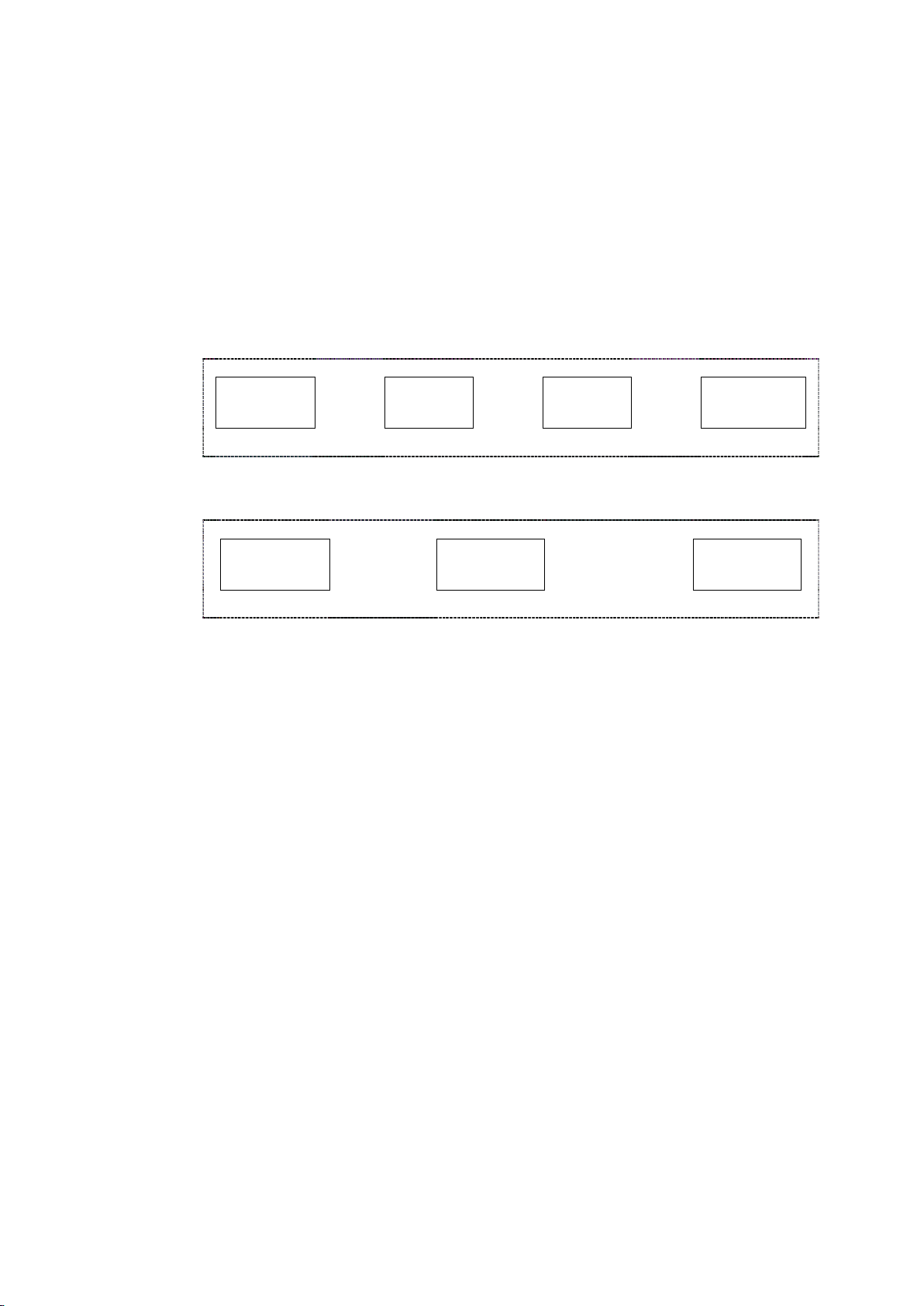
As a rule a monitoring channel is constructed with the following main
components:
Input signal
acquisition
A measuring channel without a monitoring function is constructed with the
following main components:
Input signal
acquisition
This structure is found either singly or in multiples in each channel
VIBROCONTROL 6000 Compact monitor.
Signal
processing
Monitoring channel
Signal
processing
Limit value
monitoring
Measuring channel
Output:
Analogue/Relays
Output:
Analogue
♦ The input signal acquisition is either a single-channel sensor acquisition
channel, or a two-channel process-value acquisition channel.
♦ The signal processing consists of:
− Signal filtering (e.g. acc. to DIN ISO or a variable frequency filter)
− Measured value formation: RMS-value, peak-value, DC-value,
BCU-value for rolling-element bearing monitoring, etc.
♦ Limit setpoint monitoring is carried out with reference to absolute limit
values.
♦ The measured values are available as analogue voltage or current
output signals proportional to the measured values or can be checked
with the User Terminal.
♦ Events arising out of the limit value monitoring (e.g. Alert alarms and
Danger alarms) are available as relay outputs.
Which type of input signals can be acquired ?
The following sensors can be connected:
♦ Vibration acceleration sensors (AS-sensors)
♦ Vibration velocity sensors (VS-sensors)
♦ Displacement sensors (SD/OD, resp. DS/OD and IN-sensors)
♦ Transmitters, which produce signals in the ranges 0/4-20 mA and
-15 V ... + 15 V.
© VC 6000
TM
Compact monitor Juni 2014 C100575.002 Introduction Vers.10 - 4 -
Page 15

Structure of this documentation Part A VC 6000TM Compact monitor
3 Structure of this documentation
This documentation is divided into 5 sections:
Individual instrument documentation
B. Introduction to the VIBROCONTROL 6000 Compact monitor with the
objective toward commissioning
C. Technical data for the hardware
D. The signal-flow chart components and their parameters
E. User’s dialogue of the VIBROCONTROL 6000 Compact monitor
Where can I find which type of information?
Commissioning:
When a prepared VIBROCONTROL 6000 Compact monitor is to be
taken into operation, it is generally sufficient to read individual
instrument documentation and section A.
Technical data of the module:
When your interest is in special technical data, you will find it in
section B.
Parameter settings:
When any parameters are to be edited the background information can
be found in section C.
User Terminal dialogue description:
In section D the options for communicating with the VIBROCONTROL
6000 Compact monitor
Technical schedules:
In section “Individual instrument documentation” you will find the
individual instrument documents:
via the User Terminal are described.
• Basic configuration description
• Signal-flow chart
• Configuration sheet
• Parameter setting sheet
© VC 6000
Further information:
♦ You can find further language versions of the handbook on the CD which
accompanies thrhandbook.
♦ On the internet under www.bkvibro.com you can also find further
information about the VIBROCONTROL 6000 Compact monitor .
TM
Compact monitor Juni 2014 C100575.002 Introduction Vers.10 - 5 -
Page 16

The name plate Part A VC 6000TM Compact monitor
4 The name plate
Some important information about your VIBROCONTROL 6000 Compact monitor
can be found on the name plate.
Company name
Product name
Instrument configuration
Power data
Material number
Serial number Date of manufacture
• Company name and CE mark
• Product name
• Instrument configuration and order code (different according to the
configuration)
• Power data (different according to the main power supply) and
information about the fuse protection used
• Material number:
An internal number of the delivered basic configuration
• Serial number
Instrument’s individual serial number depending on the material
number.
• Protection class identification
• In accordance with Electrical and electronics law (Elektro-G)
ADVICE
Please check that the information related to the type identification,
material number and serial number on the name plate corresponds
with the information on the signal-flow chart, configuration sheet and
parameter setting sheet. This guarantees that that the correct
documentation enclosures for the instrument are being used!
© VC 6000
TM
Compact monitor Juni 2014 C100575.002 Introduction Vers.10 - 6 -
Page 17

The signal-flow chart Part A VC 6000TM Compact monitor
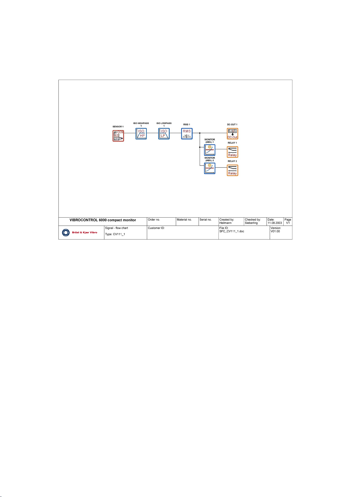
5 The signal-flow chart
The signal-flow chart describes the functional construction of the monitoring
system.
Here all the measuring and monitoring tasks with their signal-flow
components are displayed. Each signal-flow component is characterised by
its properties and parameters. The entire functionality is a result of the
cooperative operation of the individual components.
The basic properties of a measuring and monitoring task are defined by the
instrument’s implemented firmware. These properties cannot be changed at
the instrument.
Parameter settings, (e.g. limit setpoints, relay switching mode, averaging
times, DC output characteristics, etc.) can be edited using the User-terminal.
These setting options are identified in parameter configuration sheet.
Each VIBROCONTROL 6000 Compact monitor has a valid signal-flow chart
and a valid parameter configuration sheet. In this signal-flow chart and the
parameter configuration sheet all existing available components in the
system, with their links, are displayed in an overview.
NOTE:
Please document all settings that are changed so the fastest possible
assistance can be provided in case of an error. The changes can be
documented in either a parameter setting sheet.
What information is evident in the signal-flow chart?
♦ The components on the left (red frame) are assigned for acquisition of
the input signals. These input components form the interfaces for the
sensors.
♦ Components on the right (yellow frame) are assigned the task of outputs
for events that occur. These form the interfaces to external, peripheral
electronic equipment.
♦ The signal-flow chart is to be used to identify in which functional
relationship the components are linked to one another.
♦ The type identification of the basic configuration, material number and
serial number are entered in the footline of the signal-flow chart. This
information must correspond with the information on the name plate of
the VIBROCONTROL 6000 Compact monitor !
© VC 6000
TM
Compact monitor Juni 2014 C100575.002 Introduction Vers.10 - 7 -
Page 18
The signal-flow chart Part A VC 6000TM Compact monitor
Example of a signal-flow chart
© VC 6000
TM
Compact monitor Juni 2014 C100575.002 Introduction Vers.10 - 8 -
Page 19

Parameter configuration sheet Part A VC 6000TM Compact monitor
6 Parameter configuration sheet
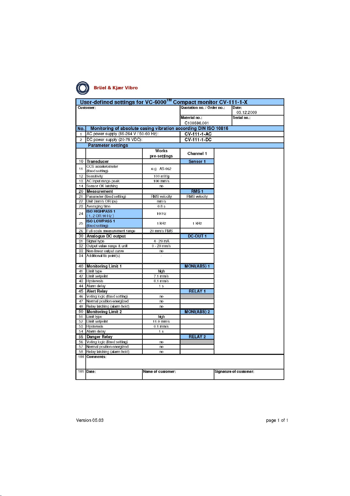
The parameters that are preset in the basic configuration are entered in the
parameter setting sheet. If the preset parameters are changed with the use
of the User Terminal, the changes can be entered on the parameter setting
sheet in a further column.
♦ Each component is listed with its parameters and pre-defined settings.
♦ Each component of the input or output modules has a parameter
<socket number>. These particulars identify the physical socket number
for the components. This information is needed to assign the connection
plugs.
♦ The displayed parameters can all be displayed on the User Terminal.
Parameters which cannot be edited are displayed the following way:
[Hardware id.]. All other parameters can be edited.
♦ The meanings and functions of the parameters, and their setting ranges
are described at the corresponding locations. (see section C:
Components of the signal-flow chart)
© VC 6000
TM
Compact monitor Juni 2014 C100575.002 Introduction Vers.10 - 9 -
Page 20
Parameter configuration sheet Part A VC 6000TM Compact monitor
Example of a parameter configuration sheet):
© VC 6000
TM
Compact monitor Juni 2014 C100575.002 Introduction Vers.10 - 10 -
Page 21
The configuration sheet Part A VC 6000TM Compact monitor
7 The configuration sheet
7.1 Configuration
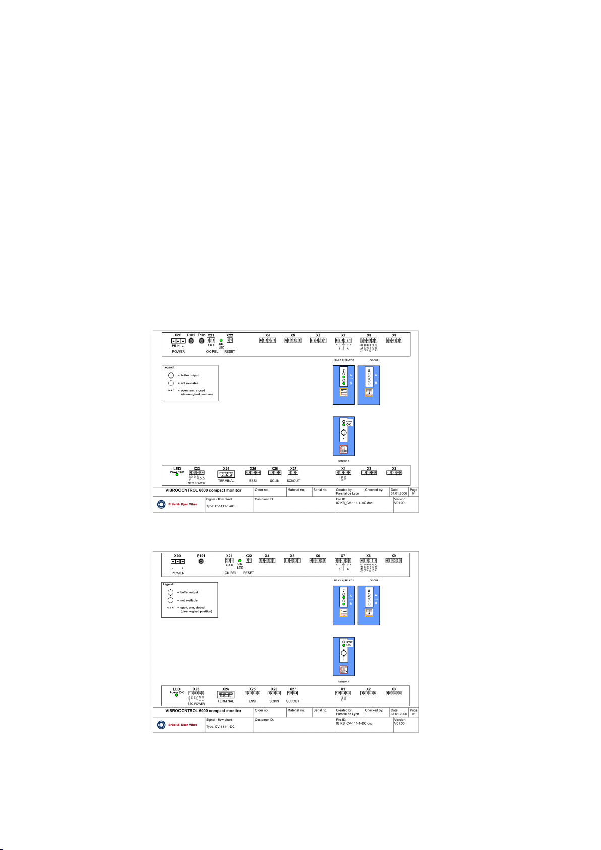
Various information is evident from the configuration sheet:
♦ Which module is to be found at which physical socket position
♦ How the connection plugs are laid out
♦ Which LEDs are assigned to which channels.
This information is required to be able to put a VIBROCONTROL 6000
Compact monitor into operation.
Example of a configuration sheet:
AC
© VC 6000
DC
TM
Compact monitor Juni 2014 C100575.002 Introduction Vers.10 - 11 -
Page 22
The configuration sheet Part A VC 6000TM Compact monitor
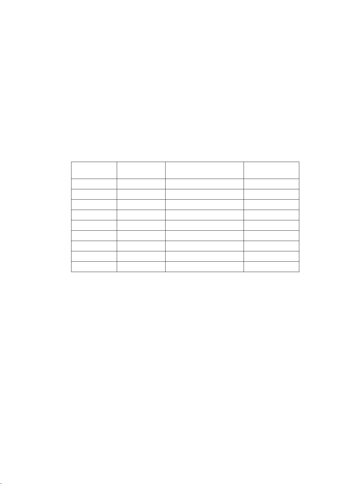
Explanation of the example:
♦ In this example not all the available sockets are occupied. Depending on
the monitoring task, it is possible that not all or other module sockets will
be necessary in a particular case.
♦ The sensor modules are at sockets 1 and 3. In the example these are
respectively input modules for AS- sensors (CCS).
♦ The 2-channel relay output modules are at sockets 7 and 9.
♦ The 2-channel DC output modules for voltage/current outputs is located
at socket 8.
7.2 Plug to socket position arrangement (in the example):
Connection
plug
X1 X1_M A-TIM (CCS) 1
Physical socket
of the module
Module in example
configuration
Description on
housing cover
X2 X2_M Not used 2
X3 X3_M A-TIM (CCS). 3
X4 X4_M Not used 4
X5 X5_M Not used 5
X6 X6_M Not used 6
X7 X7_M RELAY-OUT (2-ch.) 7
X8 X8_M DC-OUT (2-ch.) 8
X9 X9_M RELAY-OUT (2-ch.) 9
7.3 Connection plug layout
The connection plug layout differs according to the input, respectively output
modules used. In the description of the Base module (section B – Modules
Technical data) all layout options are given.
© VC 6000
TM
Compact monitor Juni 2014 C100575.002 Introduction Vers.10 - 12 -
Page 23

System reliability Part A VC 6000TM Compact monitor
8 System reliability
8.1 Standards conformity
C-ticking confirms conformity with the EMV
requirements of the Australian Government
Agency (ACA)
Safety
EN 61010-1 “
CB Test Certificate
IEC 61010-1 : 2001
EMC
EN 61326-1 “
Temperature
DIN EN 60068-2-1 : 1995-03 Cold 20 °C Working
-40 °C Storage
DIN EN 60068-2-2 : 1994-08 Dry heat +70 °C Working
+85 °C Storage
Note:
If the VC-6000 Compact monitor is mounted in a protective housing
AC-2112, the following temperature ranges are recommended:
-30 °C… +40 °C ( ambient temperature).
Housing
EN 60529: Housing protection class (IP-Code): IP 20
Electrical and electronics law (ElektroG)
WEEE-Reg.-No.: DE 69572330
Product category / application area: 9
© VC 6000
TM
Compact monitor Juni 2014 C100575.002 Introduction Vers.10 - 13 -
Page 24
System reliability Part A VC 6000TM Compact monitor
© VC 6000
TM
Compact monitor Juni 2014 C100575.002 Introduction Vers.10 - 14 -
Page 25

System reliability Part A VC 6000TM Compact monitor
8.2 Technical data
Housing
Protection class IP 20
Dimensions 311 x 170 x 113 mm (width x height x depth)
Weight, housing (empty) approx. 1,5 kg
Weight, base module approx. 450 g
Weight, plug-in module approx. 35 g
Material St 12 ZE 25/25, Surface powder-sprayed
Operating temperature range -20 °C to + 70 °C
Storage temperature range -40 °C to + 85 °C
Maximum humidity 95% non condensing
Mounting according to regulation, in a control
cabinet or protective housing!
1
Electrical power requirements
AC power supply
Input voltage range 90 ... 264 V AC
Frequency range 50 / 60 Hz
Maximum power consumption 40 VA
Power supply LED display Green = OK, OFF = Interruption
Instrument fuses (F101, F102) T2A IEC 127
size 5 x 20 mm
CAUTION!
The voltage supply may be connected only by isolating equipment (e.g.
a switch or circuit-breaker).
The device used an an isolator must fulfil the requirements of
IEC 60947-1 and IEC 60947-3 and be suitable for the application.
CAUTION HIGH VOLTAGE!
The housing cover of the VIBROCONTROL 6000 Compact monitor may be
removed only by technical personnel!!
1
Due to the principle conditions of heat development of the current outputs of the DC output modules,
a maximum of 3 DC output modules can be permitted at this ambient temperature.
© VC 6000
TM
Compact monitor Juni 2014 C100575.002 Introduction Vers.10 - 15 -
Page 26
System reliability Part A VC 6000TM Compact monitor
DC power pack
Input voltage range 20 ... 75 V DC
Maximum power consumption 22 W
Power supply LED display Green = OK; OFF = Interruption
Equipment protection T 3, 15A IEC 127
size 5 x 20 mm
Caution!
Maximally 75 V smoothed DC voltage may be attached
Advice:
The PE connection of the power supply is linked to the housing !
8.3 Operational safety of VIBROCONTROL 6000 Compact monitor
8.3.1 OK-monitoring function
The OK-monitoring function monitors the following:
♦ The power supply
♦ The microprocessor system
♦ The A/D converter
♦ The module equipment
♦ The connected sensors
When a fault occurs at one of the above, the LED is extinguished and the
associated OK-relay will change over contacts (normally-energised). The
OK-relay has potential-free contacts.
Each OK-fault is recorded in the Logbook. In the case of a serious system
error it is possible that no logbook entry will be recorded.
The OK-LED signals an error number by way of a flashing sign. Please note
the detailed information in section D „Dialogue with the User-Terminal“,
chapter „Logbook“.
© VC 6000
Electrical voltages supplied from an external source may be connected
to the relay contacts! Please note that making contact with these
voltages at the relays may cause injury or damage, even if the power to
the VIBROCONTROL 6000 Compact monitor itself is switched off.
TM
Compact monitor Juni 2014 C100575.002 Introduction Vers.10 - 16 -
Page 27

System reliability Part A VC 6000TM Compact monitor
The OK-relay in the User-terminal dialogue:
♦ In the dialogue there are one parameter for the OK-relay:
◊ Reset
♦ The parameter <Reset> in the dialogue will reset the latching OK-relay
after a fault has occurred, on condition the fault no longer exists.
♦ A further possibility for resetting the OK-relay is the parameter
<Confirm> in the dialogue in the block USER MENUS. This parameter
has the option <Reset all>. The OK-relay will also be reset with this
option.
♦ In addition the central OK-relay can also be reset remotely using a
push-button connected to the Reset input on the Base module (X22).
♦ When the monitoring function of the system is switched off (USER
MENU – Monitoring), an OK fault will be reset, but the OK-relay will only
be switched back to the fault-free status when the monitoring function is
activated once more.
8.3.2 Channel over-ranging identification function
Each A/D converter channel is permanently monitored for over-ranging.
Should it detect an over-range condition at an input channel, this is signalled
by the red LED on the input module (sensor interface or BCU CON module).
Furthermore a corresponding entry is recorded in the logbook.
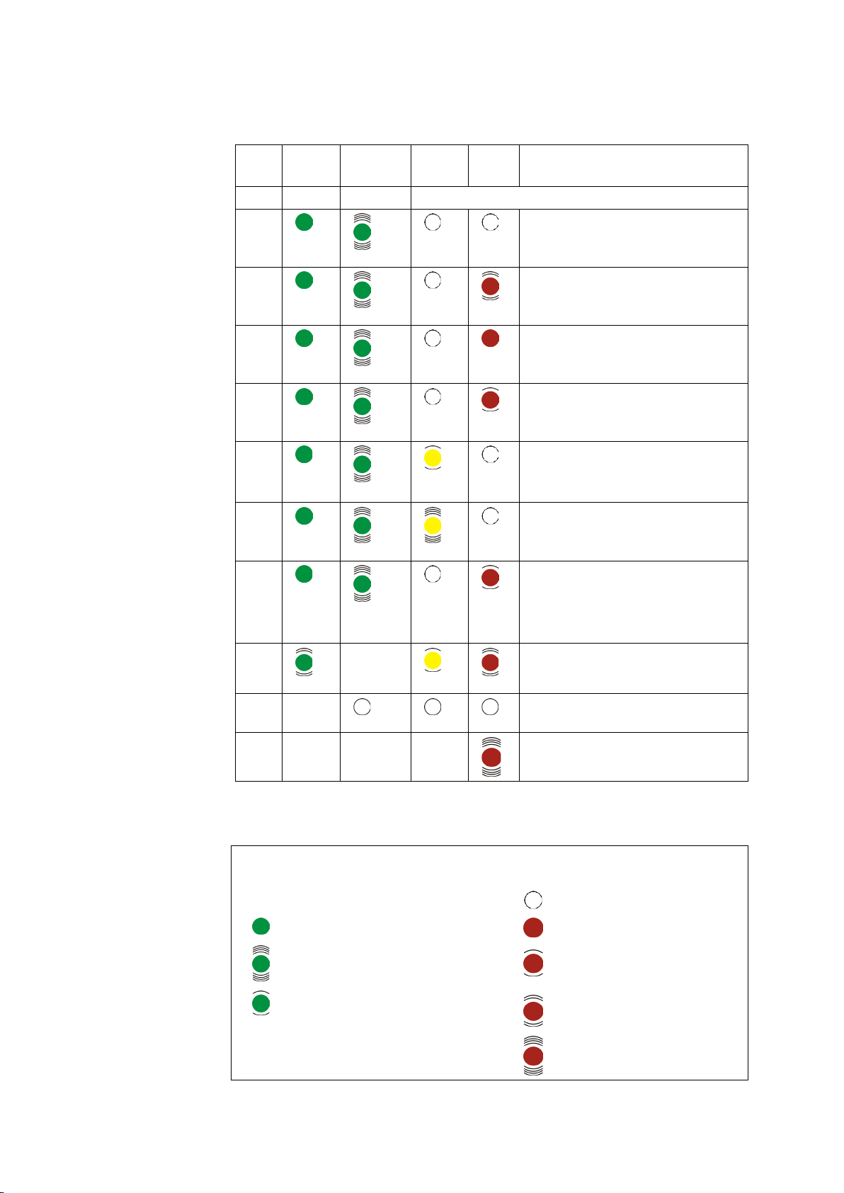
8.3.3 LED signal at a relay module
♦ As a rule a relay output signal is:directly controlled from a Monitor block.
If this occurs the LED at the relay output module is used to signal the
monitoring status and relay status. Each relay output has 2 LEDs for this
purpose, a green LED and a two-colour (red and yellow) LED.
♦ The LEDs at the relay module signal two bits of information:
◊ Functional status of the associated relay output
◊ Announcement status of the preceding Monitor block (Logic block)
© VC 6000
TM
Compact monitor Juni 2014 C100575.002 Introduction Vers.10 - 17 -
Page 28

System reliability Part A VC 6000TM Compact monitor
Switch conditions and their meaning
♦ The green LED shows the current status of a relay output.
• Relay enable off:
The relay does not operate, a limit violation is displayed only by the
LEDs
• Relay enable on:
The relay operates with a limit violation
♦ The red LED signals an existing announcement status, which as a rule
is linked to an existing Alert or Danger alarm.
♦ The yellow LED is used for signalling supplementary information, e.g.
<Trip override> active, or <Relay latching> active.
Note:
The status of the logical connection between the conditions of
TRIPOVERRIDE and ACKNOWLEDGE can be queried as a parameter in
the Logic block using the User Terminal.
© VC 6000
TM
Compact monitor Juni 2014 C100575.002 Introduction Vers.10 - 18 -
Page 29
System reliability Part A VC 6000TM Compact monitor
LEDs – Status and meanings:
Case LED
green
enabled disabled
1
2
3
4
5
6
7
8
9
10
green
green
green
green
green
green
green
green
green
green
green
green
green
green
green
off
LED
yellow
off
off
off
off
yellow
yellow
off
yellow
off
LED
red
off
red
red
red
off
off
red
red
off
Meaning
There are no violations.
A limit violation exists that has not been
reset.
A limit violation exists that has been
reset.
A limit violation existed but is no longer
present. The limit violation has not been
reset.
Only with latching relay output: A limit
violation existed that has been reset.
The relay is still latched and has not
been reset.
<Trip override> active
A limit violation has occurred but no
longer exists. The violation has not
been acknowledged.
The relay was latched but has been
reset.
Relay has an error function
Relay not configured
Wrong TIM module or TIM module
corrupted
Legend:
Green
LED
© VC 6000
TM
Compact monitor Juni 2014 C100575.002 Introduction Vers.10 - 19 -
Meaning Status of the
Relay is enabled
Relay is disabled
Relay in service
LEDs
Meaning
LED is off
LED is on
LED flashing at 0,5
Hz
LED flashing at 2
Hz
LED flashing at 8
Hz
Page 30

System reliability Part A VC 6000TM Compact monitor
8.3.4 Instrument conduct after a power failure
If there is a power failure the VIBROCONTROL 6000 Compact monitor will
be shut down and thus the monitoring function as well. In this case a
Logbook entry is always recorded.
After restoration of the power the VIBROCONTROL 6000 Compact monitor
re-initialises and auto-matically resumes its monitoring functions. A Logbook
entry is also recorded.
Alarm signals that existed before the power failure will only be recorded in
the Logbook and will no longer exist, i.e. a system cold start always effects a
complete reset of the VIBROCONTROL 6000 Compact monitor .
♦ Redundant power supply
To reduce the risk of power drop-outs of the VIBROCONTROL 6000
Compact monitor
, a second external power supply should be connected
to entrance connector X23. (Connection details can be found in section
B.) If the primary power fails this will be signalled over the message
management Prim. Power Fail (Pin 5) and Sec. Power Fail (Pin 6)). An
entry will be recorded in the Logbook. The second power supply will
take over supplying power to the VIBROCONTROL 6000 Compact
monitor. The monitoring function can then continue without interruption.
♦ Signalling of the power supply by LED
In the area of connector X23 for the redundant power supply you will
see a green LED. This LED signals the system status. This LED signals
the status of the power supply. If the LED is off there is a fault in the
power supply.
8.3.5 Error signalling through the DC output
An error in the signal path (saturation, sensor OK-fault) is signalled through
the DC output. The output value in case of an error is set to a fixed value
corresponding to the selected parameter setting, whereby a distinction must
be made between two different cases:
1. Signal output 4...20 mA / 2...10 V:
If an error occurs the output signal will drop to 2 mA or 1V.
2. Signal output 0...20 mA / 0...10 V:
If an error occurs the current output value will drop to 0 mA or 0 V
Further information about DC outputs can be found in section B – Module
Technical Data and section B – Components (DC-output block)
© VC 6000
TM
Compact monitor Juni 2014 C100575.002 Introduction Vers.10 - 20 -
Page 31
System reliability Part A VC 6000TM Compact monitor
USER MENU
REFERENCE TIME
LOGBOOK
System Info
Equipment No.
03.03.2003
System Info.
8.3.6 Significance of the logbook
Various events are recorded in the logbook. These events are divided into
three groups.
1. System messages (incl. errors in the monitoring system)
2. System access (changes in parameters of the monitoring system)
3. Monitoring events
The Logbook is displayed in a block in the dialogue of VIBROCONTROL
6000 Compact monitor
and can be viewed with the User Terminal.
More information about the contents and use of the Logbook can be found in
chapter 2 of section D „Dialogue with the User Terminal“
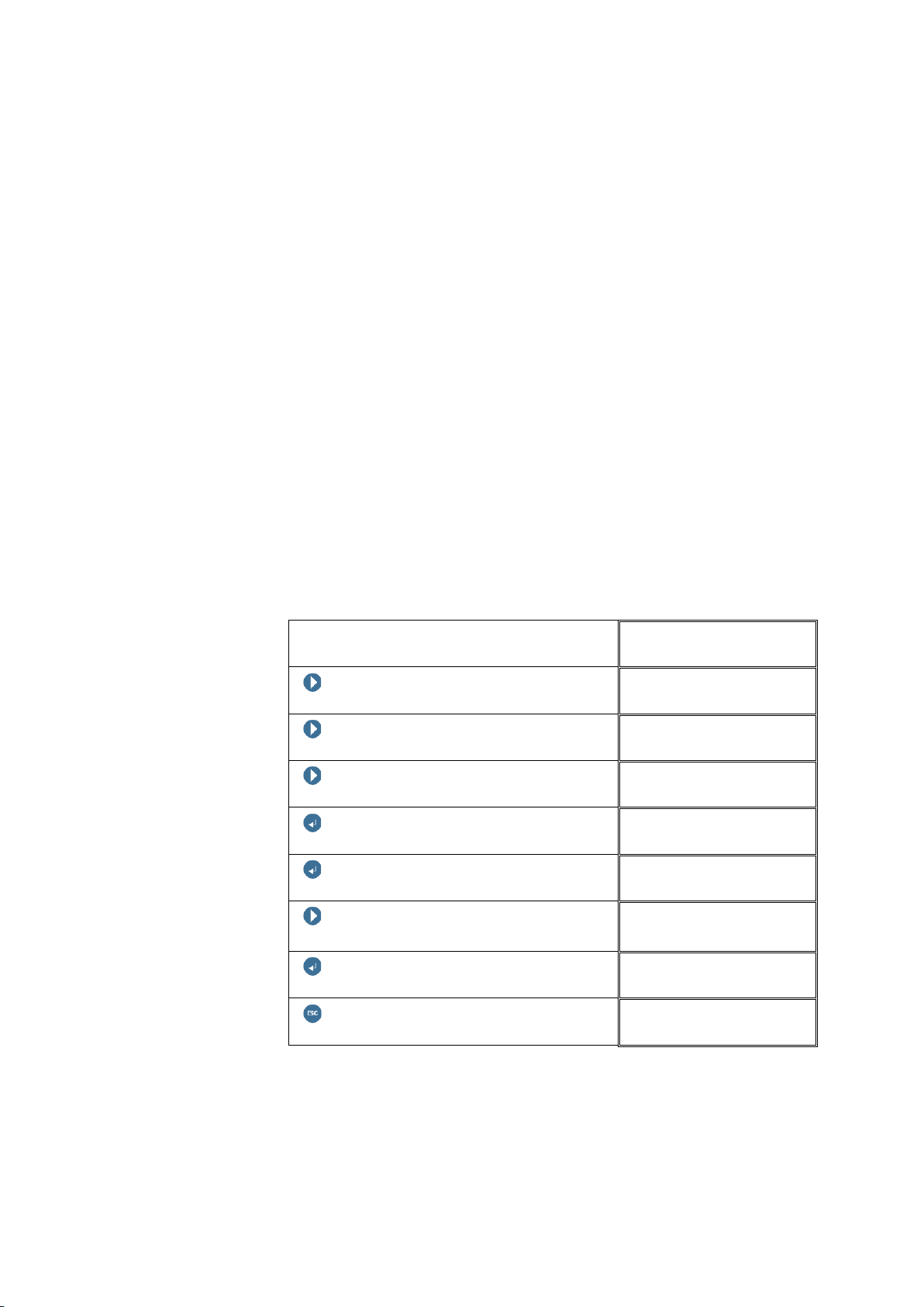
8.3.7 Calibration
We recommend that the VIBROCONTROL 6000 Compact monitor be
calibrated every 5 years. This will ensure that the correct functionality of the
system is checked, and that the certification according to the quality
standard is maintained.
The last calibration date can be called to the dialogue with the User
Terminal.
This is found in the System block under System Info.
User Terminal button
NEXT
NEXT
SYSTEM
NEXT
ENTER BUTTON
ENTER BUTTON
NEXT (repeat until <Last Calibr.>
appears
ENTER BUTTON
SYSTEM
System Info
System Info
Last Calibr.
Last Calibr.
© VC 6000
ESCAPE
SYSTEM
The last calibration date can only be read with the User Terminal but cannot
be changed!
More detailed information about the handling with the User Terminal can be
found in section D „Dialogue with the User Terminal“
TM
Compact monitor Juni 2014 C100575.002 Introduction Vers.10 - 21 -
Page 32
Mounting and Installation Part A VC 6000TM Compact monitor
9 Mounting and Installation
9.1 Safety advice
The general safety advice of Brüel & Kjær Vibro GmbH is
applicable.
♦ The safety advice must be read and understood before putting the
instrument into operation!
♦ All installation work must be carried out without power to the instrument!
♦ If parameters setting changes are to be carried out during operation,
you should take into consideration the effect of the changes on the
active monitoring function!
♦ Switch off the power to the instrument before cleaning!
The instrument can be cleaned using a damp cloth. Do not spray water
or any other fluids onto the instrument!
♦ Connect only the power specified on the name plate!
♦ All cables must be laid out in such a manner that they cannot be
damaged!
♦ Observe all grounding instructions for the instrument and screened
cables!
♦ Electro static discharge upon the connectors may cause damage!
♦ CAUTION! The voltage supply may be connected only by isolating
equipment (e.g. a switch or circuit-breaker).The device used an an
isolator must fulfil the requirements of IEC 60947-1 and IEC 60947-3
and be suitable for the application.
© VC 6000
TM
Compact monitor Juni 2014 C100575.002 Introduction Vers.10 - 22 -
Page 33
Mounting and Installation Part A VC 6000TM Compact monitor
9.2 Site conditions
With the installation of the VIBROCONTROL 6000 Compact monitor the
following requirements for site conditions must be observed:
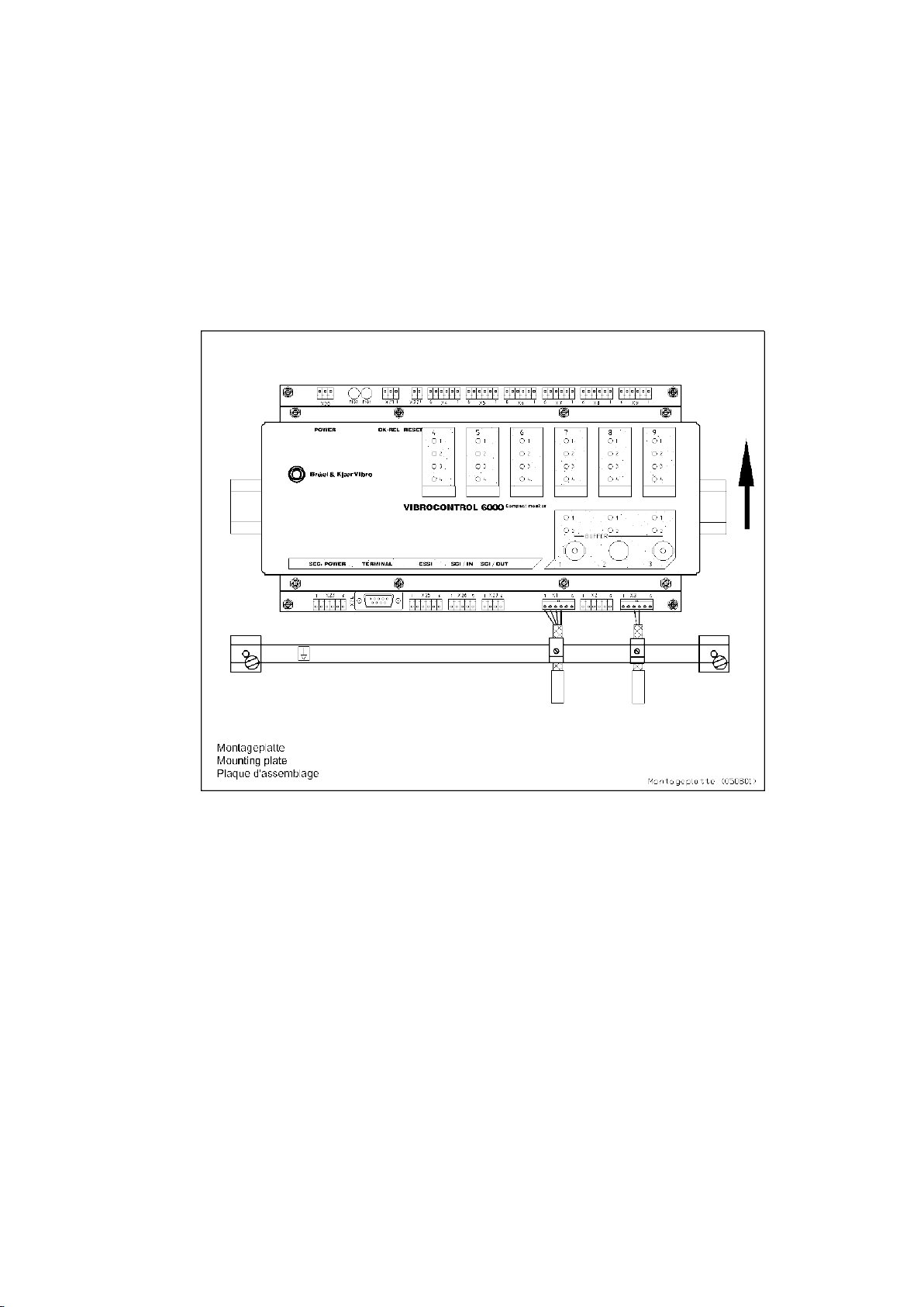
♦ VIBROCONTROL 6000 Compact monitor is designed for mounting onto
a mounting rail according to DIN EN 50022.
♦ VIBROCONTROL 6000 Compact monitor is to be mounted horizontally
on the mounting rails, see drawing:
© VC 6000
TM
Compact monitor Juni 2014 C100575.002 Introduction Vers.10 - 23 -
Page 34
Mounting and Installation Part A VC 6000TM Compact monitor
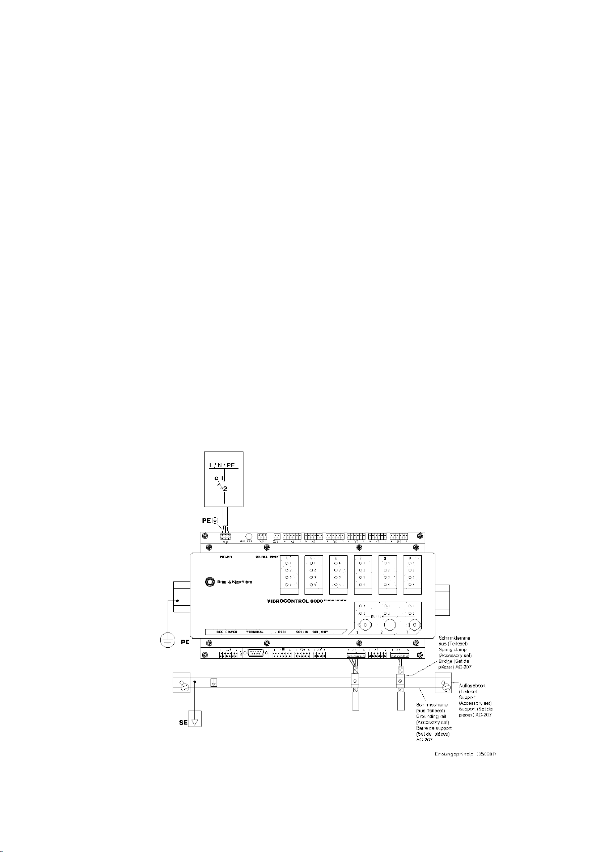
9.3 Grounding concept for VIBROCONTROL 6000 Compact monitor
Optimum screening is obtained, when a separate protective ground (SE) to
the potential-equalisation ground (PE) is available.
♦ The screen of the connecting cable should be made flat when being
connected to the grounding rail.
♦ The housing of the VIBROCONTROL 6000 Compact monitor is
connected through the power supply and mounting rail to PE.
♦ Further advice for correct grounding of the housing and cable screens
can be found in the brochure „General grounding prescriptions“.
♦ Ideally the grounding rail should be isolated from PE and connected to a
separate protective ground. For this purpose the isolated supports
(AB/SS) in the accessory set should be used for securing the collective
rail.
♦ If there is no separate protective ground available for the screen rail, a
connection to the mounting plate can be made with the supports which
make contact (AB/SS-M).
♦ All input signals (X1 / X2 / X3) are to be connected to the
VIBROCONTROL 6000 Compact monitor through screened cables. The
cable screens should be made flat when being connected to the
grounding rail.
Grounding concept for VIBROCONTROL 6000 Compact monitor :
© VC 6000
TM
Compact monitor Juni 2014 C100575.002 Introduction Vers.10 - 24 -
Page 35
Mounting and Installation Part A VC 6000TM Compact monitor
9.4 Mounting the instrument
9.4.1 Mounting on a rail according to DIN EN 50022
♦ The mounting of the VIBROCONTROL 6000 Compact monitor has to be
done according to the regulation in a control cabinet or protective
housing !
♦ Position the VIBROCONTROL 6000 Compact monitor on the rail and
push downward until the instrument clips onto the rail.
♦ Check that the VIBROCONTROL 6000 Compact monitor is securely
fixed to the rail!
9.4.2 Removing from a rail
♦ For removal from a rail you need an adequately large, flat screwdriver.
♦ First of all lever one side of the clip device downward using the
screwdriver.
Then loosen the housing of the VIBROCONTROL 6000 Compact
monitor from the rail on the same side by hand.
♦ Then lever the other side clip device downward using the screwdriver.
Now loosen this side of the housing from the rail.
♦ The VIBROCONTROL 6000 Compact monitor can now be removed.
9.5 Making the connections
The electrical connections to the VIBROCONTROL 6000 Compact monitor
may be carried out only by technical personnel!
It is important to observe the grounding instructions!
Depending on how the VIBROCONTROL 6000 Compact monitor
various connections will be made. See the corresponding configuration
sheet for the instrument to determine which modules are contained in the
VIBROCONTROL 6000 Compact monitor . (See also chapter 8
„Commissioning“).
is built up
© VC 6000
TM
Compact monitor Juni 2014 C100575.002 Introduction Vers.10 - 25 -
Page 36
Mounting and Installation Part A VC 6000TM Compact monitor
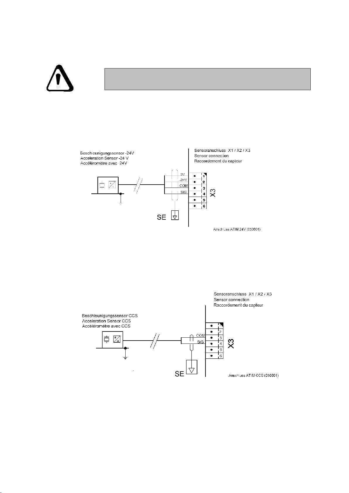
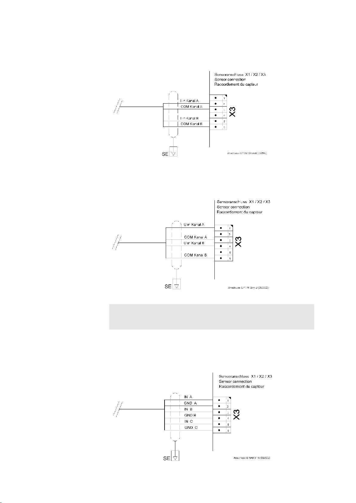
9.5.1 Wiring and connection of sensors
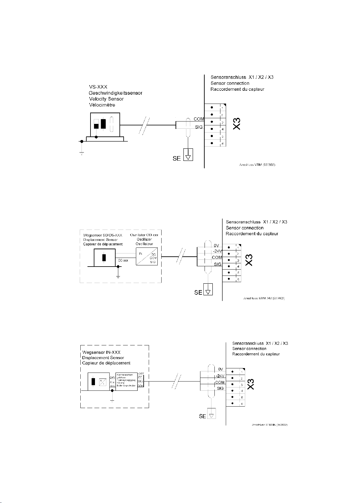
The following connection diagrams are principle illustrations; please
always observe the corresponding documentation, the sensors that
will be connected or the subsequent electronics!
9.5.1.1 Acceleration sensors with –24 V DC power at A-TIM (-24 V)
9.5.1.2 Acceleration sensors with constant-current power (CCS) at A-TIM (CCS)
© VC 6000
TM
Compact monitor Juni 2014 C100575.002 Introduction Vers.10 - 26 -
Page 37
Mounting and Installation Part A VC 6000TM Compact monitor
9.5.1.3 Vibration velocity sensors at V-TIM (8 Hz/15 Hz)
9.5.1.4 Displacement sensors at D-TIM
© VC 6000
TM
Compact monitor Juni 2014 C100575.002 Introduction Vers.10 - 27 -
Page 38
Mounting and Installation Part A VC 6000TM Compact monitor
9.5.1.5 0/4..20 mA signals at GP input module (GP-TIM)
9.5.1.6 0/2...10 V signals at GP input module (GP-TIM)
Note:
At one GP-TIM either two current inputs or two voltage inputs can be
used. A mixture of the two signal types at one GP-TIM is not possible!
9.5.1.7 3-channel input module for binary status signals
© VC 6000
TM
Compact monitor Juni 2014 C100575.002 Introduction Vers.10 - 28 -
Page 39
Mounting and Installation Part A VC 6000TM Compact monitor
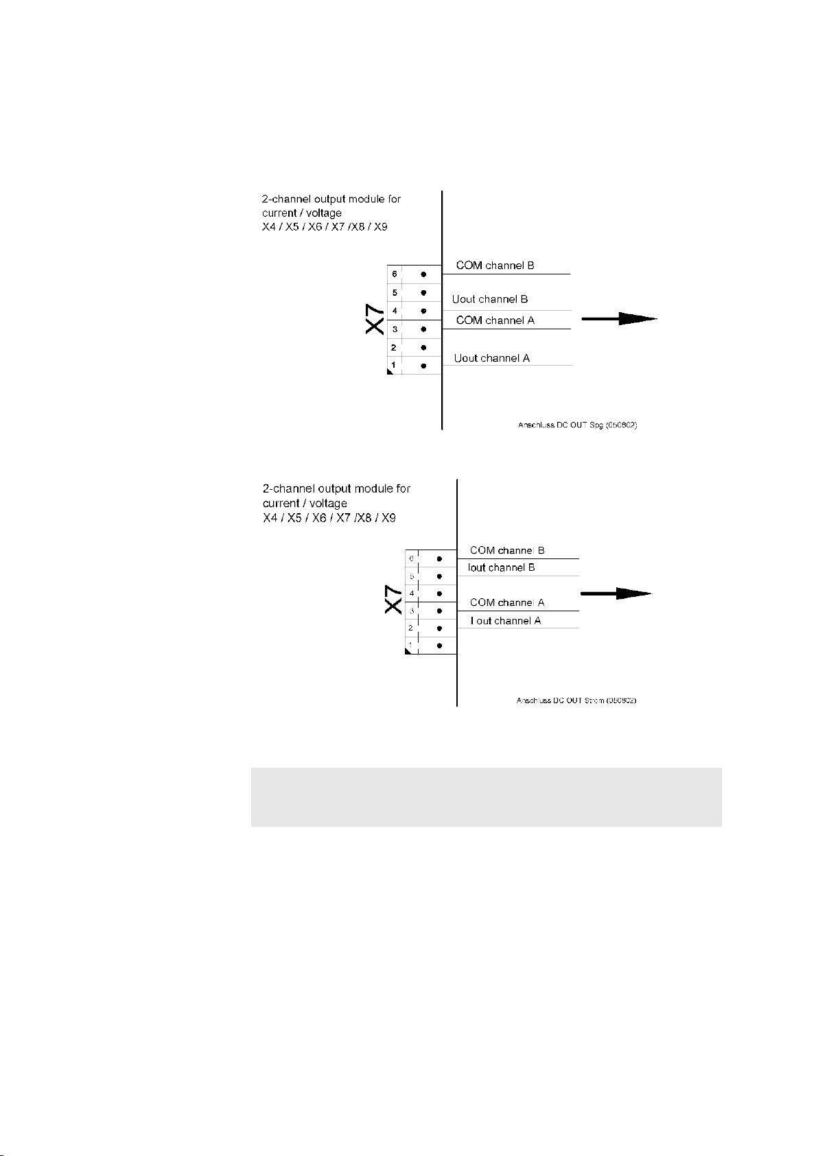
9.5.2 Wiring and connection of peripheral equipment
9.5.2.1 DC output at DC-OUT (2-ch.)
© VC 6000
Note:
TM
Compact monitor Juni 2014 C100575.002 Introduction Vers.10 - 29 -
A current or a voltage output signal may be selected for each channel
separately. They do not have to be the same type of output signals !
Page 40
Mounting and Installation Part A VC 6000TM Compact monitor
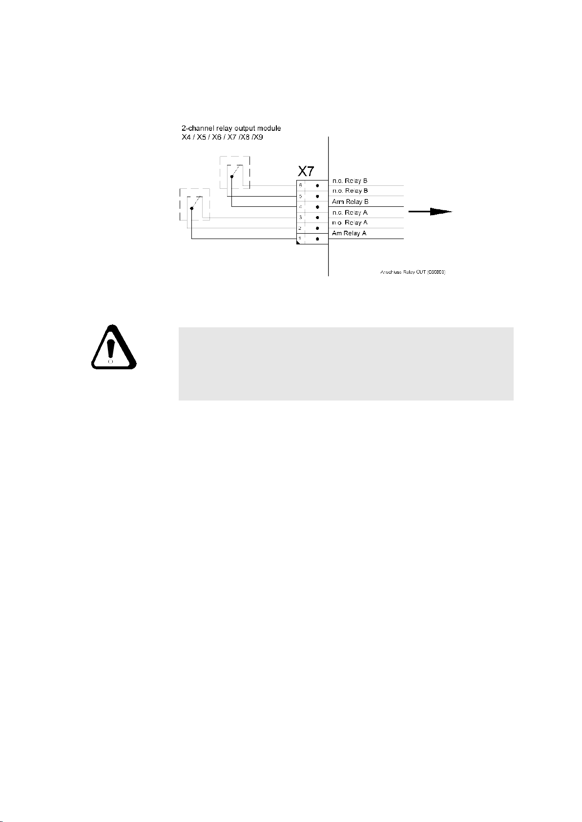
9.5.2.2 Relay output at RELAY-OUT(2-ch.)
CAUTION:
Because external voltages are connected to the relay contacts, there
may be dangerously high voltages at these contacts even after the
power to the VIBROCONTROL 6000 Compact monitor has been
switched off.
The maximum voltages and switching capacity of the relays must be
strictly observed (see section B: Relays technical data).
© VC 6000
TM
Compact monitor Juni 2014 C100575.002 Introduction Vers.10 - 30 -
Page 41
Mounting and Installation Part A VC 6000TM Compact monitor
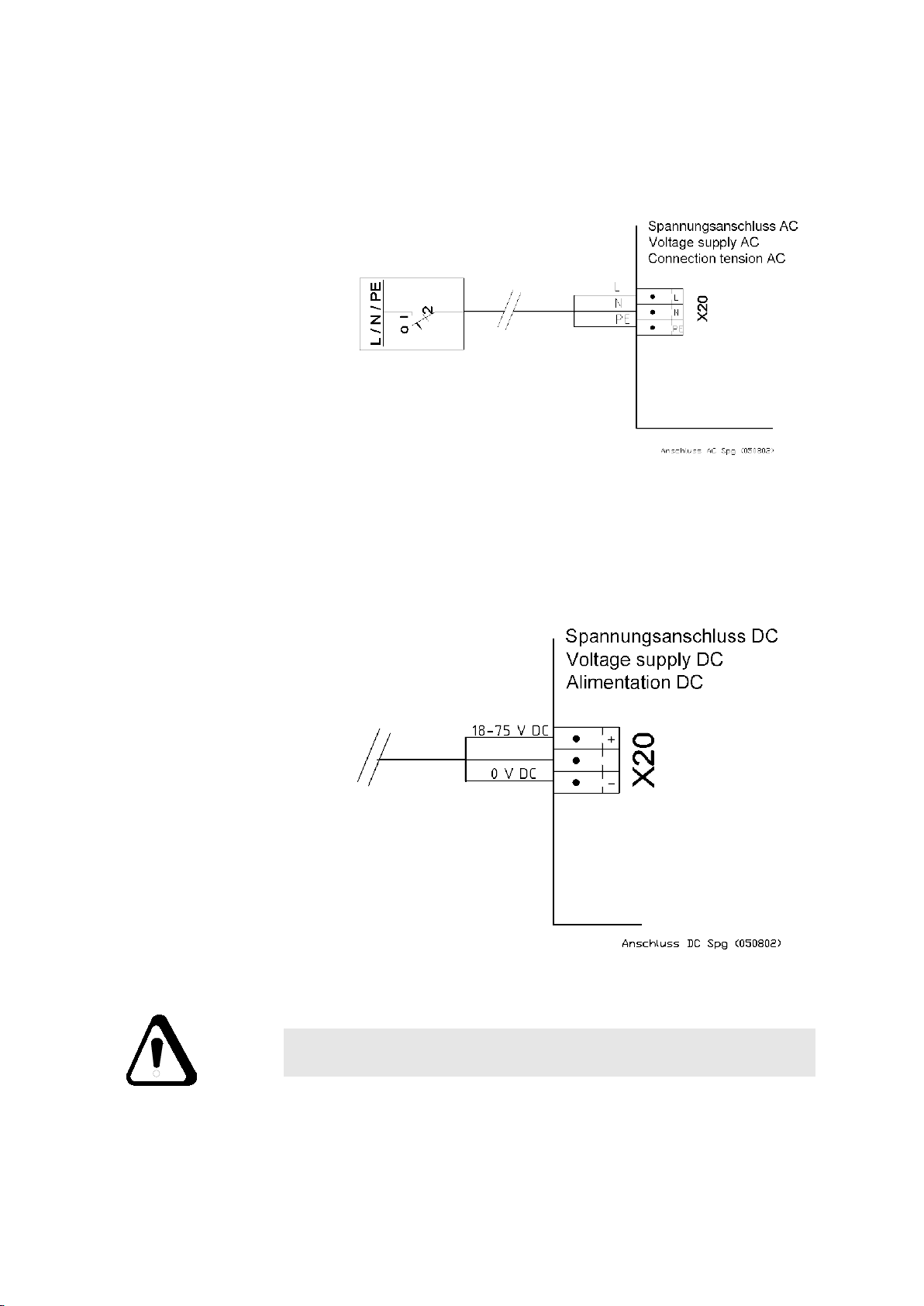
9.5.3 System connections
9.5.3.1 AC power supply
Recommended cross-sectional area for the connecting cables: 1,5 mm²
9.5.3.2 DC power supply
© VC 6000
Recommended cross-sectional area for the connecting cables: 1,5 mm²
Caution!
TM
Compact monitor Juni 2014 C100575.002 Introduction Vers.10 - 31 -
Maximally 75 V smoothed DC voltage may be attached
Page 42
Mounting and Installation Part A VC 6000TM Compact monitor
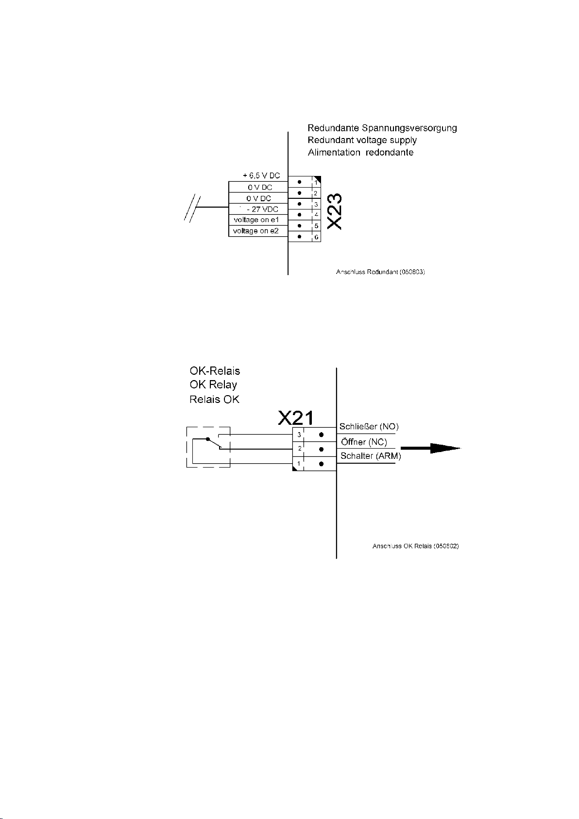
9.5.3.3 Redundant power supply input
9.5.3.4 OK relay
© VC 6000
TM
Compact monitor Juni 2014 C100575.002 Introduction Vers.10 - 32 -
Page 43
Mounting and Installation Part A VC 6000TM Compact monitor
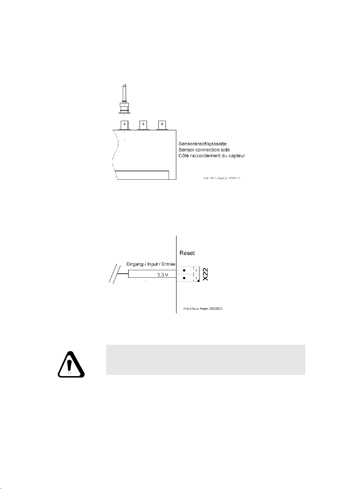
9.5.3.5 Buffered outputs
The buffered outputs are at BNC sockets, located on each sensor input
module.
9.5.3.6 Reset input
CAUTION!
The peripheral components connection variants shown here do not
claim to be comprehensive or complete.
Please also consult the technical documentation of the peripheral
equipment you wish to connect to the VIBROCONTROL 6000 Compact monitor!
© VC 6000
TM
Compact monitor Juni 2014 C100575.002 Introduction Vers.10 - 33 -
Page 44
Mounting and Installation Part A VC 6000TM Compact monitor
9.6 Commissioning and function testing
9.6.1 Commissioning
♦ Signal-flow chart and configuration sheet
An individual signal-flow chart and configuration sheet exists for each
VIBROCONTROL 6000 Compact monitor .
These two documents can be found at two locations:
1. In a document pocket on the housing cover of the VIBROCONTROL
6000 Compact monitor
strip which you can use to attach it e.g. to the control cabinet door.
The document pocket with the individual instrument documents
should be secured in the near vicinity of the installed
VIBROCONTROL 6000 Compact monitor for ready access.
2. In section individual instrument documentation of the handbook.
♦ Checking the instrument using the signal-flow chart and the
configuration sheet:
. The document pocket has an adhesive
The signal-flow chart shows the structure of the VIBROCONTROL 6000
Compact monitor ; the configuration sheet shows the physical
construction and the connection plug layout.
Using this documentation please check your VIBROCONTROL 6000
Compact monitor .
♦ Making the connections
The connections should be made only by technical personnel!
The connections for the input signals, output signals, reporting signals
and power supply can be identified using the configuration sheet.
We recommend that the connections be made in the following
sequence:
1. The input signals (sensors) = X1 / X2 / X3
2. The output signals (current/voltage outputs, relays) = X4 to X9
3. The reporting signals (OK relay, Power fail) = X21, X23
4. The power supply = X20
♦ How to switch on?
After establishing the power supply the VIBROCONTROL 6000
Compact monitor will be switched on. The instrument will self-load the
firmware in the back-ground of the Flash memory.
© VC 6000
TM
Compact monitor Juni 2014 C100575.002 Introduction Vers.10 - 34 -
Page 45
Mounting and Installation Part A VC 6000TM Compact monitor
♦ What happens after the start-up?
The VIBROCONTROL 6000 Compact monitor
correspond to the require-ments of the application. When all the sensors
are correctly installed the monitoring task proceeds 10s after being
switched on.
In applications that contain at least one V-TIM the settling time amounts
to approx. 45 seconds. During this time all modules, i.e. all LEDs, relays
and current outputs, assume the condition they had at the last save
action.
If there is an error on the side of the sensors, this will be signalled by the
LEDs on the sensor modules and the relay modules and by the OK LED
(Please consult also chapter 8.3.3
♦ What to do in case of an error?
In case of an error we recommend that you connect the User-terminal
and check out the contents of the logbook.
9.6.2 Function testing
♦ How will I know that the VIBROCONTROL 6000 Compact monitor is
functioning correctly?
All LEDs will be green and the connected outputs will be signalling no
errors.
♦ What are the meanings of the LED signals at the sensor and relay
modules?
is configured to
).
Please consult chapter 6.2.3
♦ Function testing with the User Terminal
We recommend that you check all the settings with the User Terminal
after the instrument start-up.
Connect the User Terminal to the VIBROCONTROL 6000 Compact
r at the connection plug X24 (DSUB connection). The User
monito
Terminal will login with a display of the Start screen, or the request for
entry of the CLOCK REFERENCE (date and time) will appear.
It is important that the CLOCK REFERENCE (date and time) be set up
so that future entries in the logbook can be correctly recorded.
When you carry out the CLOCK REFERENCE set-up consult section D
„Dialogue with the User-terminal“.
Then check out the parameter settings entered in the signal-flow chart.
♦ Are the parameter settings correct?
Now check the signal-flow chart for the parameter settings entered
there.
The VIBROCONTROL 6000 Compact monitor
correspond with the require-ments of the application. As a rule the
sensor settings, processing criteria and limit setpoints will correspond to
the works pre-settings.
is configured to
© VC 6000
These works pre-settings must be adapted to the known monitoring task
(e.g. other sensor sensitivity, other limit setpoint settings.
These changes can be made with the User Terminal using the SUPER
USER password. (See section D: Dialogue with the User Terminal)
TM
Compact monitor Juni 2014 C100575.002 Introduction Vers.10 - 35 -
Page 46

Digital Communication Part A VC 6000TM Compact monitor
10 Digital Communication
The VIBROCONTROL 6000 Compact monitor is able to export its
continuously acquired measurement data also as digital data. For this
purpose an OPC interface, which can optionally be integrated in a TCP/IP
Ethernet network, is available. With this function the VIBROCONTROL 6000
Compact monitor is a data source which makes your measured data and
status information available to a OPC-server (OPC DA-server – Type 7131)
in a prepared form.
Through the use of the OPC-interface it is possible to pass the data further
to process visualization systems.
For the data transfer the SCI-interface of the VIBROCONTROL 6000
Compact monitor
is used together with an RS-232 converter (AC-5004).
If the VIBROCONTROL 6000 Compact monitor
is connected to a network, a
Gateway (AC-5002) is also required.
Detailed information about the SCI-interface can be found in section
B – Basic module.
Infomation about the configuration of this interface can be found in section
C – COM-Block.
Infomation about the OPC-server can be found in the OPC DA-server –
Type 7131 handbook.
Infomation about the RS-232 converter is found in the AC-5003 data sheet.
Information about the Gateway is found in the AC-5002 data sheet.
© VC 6000
TM
Compact monitor Juni 2014 C100575.002 Introduction Vers.10 - 36 -
Page 47
Typical measurement tasks Part A VC 6000TM Compact monitor
11 Typical measurement tasks
11.1 General
As a rule the parameters to be set up are dependent on the application. All
the parameters of an application are marked in the signal-flow chart.
The parameters that can be changed are correspondingly identified.
Some parameters are always set the same at our works. These parameters
are dealt with in the next chapter.
11.2 Works settings for the basic configurations
11.2.1 Absolute housing vibration according to DIN ISO 10816
Input sensitivity For vibration acceleration sensors 100 mV/g
For vibration velocity sensors
(e.g. VS-068/VS-069) 100 mV/mm/s
Measurement type RMS value of vibration velocity from 10 Hz to 1 kHz
Measurement range 0...20 mm/s RMS with a Crest Factor 5 (= 0 ... 100 mm/s input
range)
Averaging time 800 ms
Measurement
accuracy
DC-output 4 ... 20 mA corresponding to 0 ... 20 mm/s RMS
Monitoring Alert alarm: Limit value 7.1 mm/s; relay delay time 1 s
Relay output Alert alarm: Normally de-energized, non-self-latching
< 0,75 % of measured value
(with analogue integration < 2,75 % of measured value)
plus 0,1 % of measurement range full-scale value
Danger alarm: Limit value 11 mm/s; relay delay time 1 s
Danger alarm: Normally de-energized, non-self-latching
© VC 6000
TM
Compact monitor Juni 2014 C100575.002 Introduction Vers.10 - 37 -
Page 48
Typical measurement tasks Part A VC 6000TM Compact monitor
11.2.2 Rolling-element Bearing Condition Unit – BCU
Input sensitivity For vibration acceleration sensors 100 mV/g
Measurement range 0 ... 100 BCU
Averaging time 1 s
Measurement
accuracy
Monitoring Alert alarm: Limit value 1 BCU; relay delay time 1 s
Relay output Alert alarm: Normally de-energized, non-self-latching
< 4,5 % of measured value plus 0,2 % of measurement range
full-scale value
Danger alarm: Limit value 2 BCU; relay delay time 1 s
Danger alarm: Normally de-energized, non-self-latching
11.2.3 Rolling-element bearing condition BC-BP (bearing condition
bandpass)
Input sensitivity For vibration acceleration sensors 100 mV/g
Measurement type RMS value of vibration acceleration from 1 kHz to 10 kHz
Measurement range 0 ... 16 g RMS at a Crest Factor of 5 (= 0 ... 80 g peak value)
Averaging time 800 ms
Measurement
accuracy
< 0,75 % of measured value plus 0,2 % of measurement range
full-scale value
© VC 6000
Monitoring Alert alarm: Limit value 1 g; relay delay time 1 s
Danger alarm: Limit value 4 g; relay delay time 1 s
Relay output Alert alarm: Nromally de-energized, non-self-latching
Danger alarm: Normally de-energized, non-self-latching
TM
Compact monitor Juni 2014 C100575.002 Introduction Vers.10 - 38 -
Page 49
Typical measurement tasks Part A VC 6000TM Compact monitor
11.2.4 Relative shaft vibration acc. to DIN ISO 7919
oder
Input sensitivity
Measurement type s
For displacement sensors 8 mV/µm
in the frequency range from 10 Hz to 1 kHz
max
resp. Max (x,y) peak-peak in the frequency range from
10 Hz to 1 kHz
Measurement range
0 ... 250 µm for s
/ 0 ... 500 µm for Max (x,y)
max
Peak-value detector Rise-time 3 ms, decay-time 5 s
Measurement
accuracy
for peak-peak < 0,75 % of measured value / for s
measured value
< 1% of
max
plus 0,1 % of measurement range full-scale value
DC-output
4 ... 20 mA corr. to 0 ... 250 µm (s
) resp. 0 ... 500 µm
max
(Max (x,y))
Monitoring
Alert alarm: Limit value 50 µm resp. 100 µm;
relay delay time 1 s
Danger alarm: Limit value 70 µm resp. 140 µm;
relay delay time 1 s
Relay output Alert alarm: Normally-de-energized, non-self-latching
Danger alarm: Normally de-energized, non-self-latching
11.2.5 Axial shaft position
Inuput sensitivity
Measurement type Static displacement (DC-value) of axial shaft position
Measurement range -1 ... + 1 mm
Averaging time 1 s
Measurement
accuracy
DC-output 4 ... 20 mA corr. to –1 ... + 1 mm
Monitoring Alert alarm: Limit value +/- 0,5 mm; relay delay time 1 s
Relay output Alert alarm: Normally de-energized, non-self-latching
For displacement sensors - 8 mV/µm
< 0,75 % of measured value, plus 1 % of measurement range
full-scale value
Danger alarm: Limit value +/- 0,8 mm; relay delay time 1 s
Danger alarm: Normally de-energized, non-self-latching
© VC 6000
TM
Compact monitor Juni 2014 C100575.002 Introduction Vers.10 - 39 -
Page 50
Typical measurement tasks Part A VC 6000TM Compact monitor
11.2.6 Process value
Input sensitivity 4 ... 20 mA corr. to 0 ... 150 eu
Measurement type Quasi-static process value (DC-value)
Measurement range 0 ... 150 eu
Averaging time 1 s
Measurement
accuracy
11.2.7 Speed
Input sensitivity 1 mV/mV
Measurement type Shaft speed in [rpm]
Factor & Divisor Resp. 1 (corr. to 1 impulse per revolution)
Measurement time 0,5 s
Max. impulse interval 1 s
Measurement
accuracy
11.2.8 Rod-drop
< 1 % of measured value plus 0,1 % of measurement range
full-scale value
Approx. 0.01 % of measured value
© VC 6000
Input sensitivity
Measurement type Cycle DC-value of the geometrically corrected rod-drop
Measurement range 4 mm (without geometric correction)
Averaging time 50 cycles
Operating type Customer-specific (one position, two positions or averaged
Measurement
position in the cycle
Measurement
accuracy
TM
Compact monitor Juni 2014 C100575.002 Introduction Vers.10 - 40 -
For displacement sensors 4 mV/µm
cycle)
Customer-specific
< 0,75 % of measured value plus 1 % of measurement range
full-scale value
Page 51
Typical measurement tasks Part A VC 6000TM Compact monitor
11.2.9 Vector
Input sensitivity For vibration acceleration sensors 100 mV/g
For vibration velocity sensors
(e.g. VS-068/VS-069) 100 mV/mm/s
For displacement sensors 8 mV/µm
Measurement type Vector of 1n, with magnitude and phase
Signal detection RMS
Bandwidth 22 %
Max. impulse interval 1 s
Measurement
accuracy
< 1 % of measured value plus 0,2 % of measurement range
full-scale value;
for phase information < 2°
(valid under steady-state conditions with a measurement time
> 100 ms)
© VC 6000
TM
Compact monitor Juni 2014 C100575.002 Introduction Vers.10 - 41 -
Page 52

Contents index for the following documentation Part A VC 6000TM Compact monitor
12 Contents index for the following documentation
Section B: Technical data of the modules
1 BASE Module
2 1-channel input module for acceleration sensors
3 1-channel input module for vibration velocity sensors
4 1-channel input module for displacement sensors
5 2-channel input module for current / voltage
6 2-channel conditioning module for BCU
7 3-channel input module for binary status signals
8 2-channel Relay output module
9 2-channel output module for current / voltage
© VC 6000TM Compact monitor Juni 2014 C100575.002 Introduction Vers.10 - 42 -
Page 53

Contents index for the following documentation Part A VC 6000TM Compact monitor
Section C: Description of signal-flow chart components
1 Sensor block
2 Sensor-(A/B) block
3 Binary in block
4 Highpass / Lowpass Filter
5 Trigger block
6 BCU Measurement
7 DC Measurement
8 Speed Measurement
9 Peak Measurement
10 Peak-Peak Mesurement
11 RMS Measurement
12 S
Measurement
max
13 Vector Measurement
14 Cyclic DC Measurement
15 Computed Values
16 Monitor block (1 absolute limit)
17 Dual-Monitor block (2 absolute limits)
18 Logic block
19 DC Output
20 Relay Block
21 Communication (COM) block
© VC 6000TM Compact monitor Juni 2014 C100575.002 Introduction Vers.10 - 43 -
Page 54

Contents index for the following documentation Part A VC 6000TM Compact monitor
Section D: Dialogue with the User-terminal
1 User Terminal
2 Function
3 Advice about the documentation
4 Logging in to the system
5 Setting reference time
6 Navigating the signal-flow charts
7 Displaying parameters
8 Display of measurements
9 Setting the sensor sensitivity and input range
10 Setting limit setpoints and time delays
11 Logbook
12 System block
13 Communication block
© VC 6000TM Compact monitor Juni 2014 C100575.002 Introduction Vers.10 - 44 -
Page 55

B
Module - Technische Daten
Modules - Technical Data
Modules - Charactéristique technique
VC-6000 Compact monitor
Page 56

All rights reserved.
No part of this publication may be reproduced, stored in a retrieval system or
transmitted, in any form, or by any means, electronic, mechanical,
photocopying, recording or otherwise without prior written permission from
Brüel & Kjær Vibro GmbH.
The right to make changes at any time without notice is reserved.
Copyright 2014 by Brüel & Kjær Vibro GmbH, D-64293 Darmstadt
Tel.: +49 (0)6151 428 –1400 Fax: +49 (0)6151 428 –1401
Page 57

Contents Part B VC-6000TM Compact monitor
Contents – Modules Technical Data
BASE Module 5
1
1.1 Function 5
1.2 Construction 6
1.2.1 AC-board construction 6
1.2.2 DC-board construction 6
1.3 Connection plugs on the Base Module 7
1.3.1 Overview 7
1.3.2 Socket position and assigned connection plug 8
1.4 The connections – their function and layout 9
1.4.1 Sensor Interface Module: Connections X1, X2 and X3 9
1.4.2 Output and supplementary modules: Connections X4 to X9 11
1.4.3 System: Connections X20 to X27 12
1.5 Technical data 16
1.5.1 Electrical power supply 16
1.5.2 Mechanical execution 16
1.5.3 System 17
2 1-channel input module for acceleration sensors 18
2.1 Function 18
2.2 Signal path 19
2.3 Technical data 20
2.3.1 Electrical properties 20
2.3.2 Equipment and signalling 21
© VC-6000
TM
Compact monitor Nov, 2014 C100584.002 Module Vers. 08 - 1 -
Page 58

VC-6000TM Compact monitor Part B Contents
3 1-channel input module for vibration velocity sensors 23
3.1 Function 23
3.2 Signal path 23
3.3 Technical data 24
3.3.1 Electrical properties 24
3.3.2 Equipment and signalling 25
4 1-channel input module for displacement sensors 27
4.1 Function 27
4.2 Signal path 27
4.3 Technical data 28
4.3.1 Electrical properties 28
4.3.2 Equipment and signalling 28
5 2-channel input module for current / voltage 30
5.1 Function 30
5.2 Technical data 30
5.2.1 Electrical properties 30
5.2.2 Equipment and signalling 31
6 2-channel conditioning module for BCU 32
6.1 Function 32
6.2 Technical data 32
6.2.1 Electrical properties 32
6.2.2 Equipment and signalling 33
- 2 - C100584.002 Module Vers. 08 © VC-6000
TM
Compact monitor Nov. 2014
Page 59

Contents Part B VC-6000TM Compact monitor
7 3-channel input module for binary status signals 34
7.1 Function 34
7.2 Technical data 34
7.2.1 Electrical properties 34
7.2.2 Equipment and signalling 35
7.3 Wiring of binary inputs 36
7.3.1 External potential-free contacts (non-active signals) 36
7.3.2 Active signals from external current sources (PNP open- collector) 36
7.3.3 Active signals from external current sinks (NPN open-collector) 37
8 2-channel Relay output module 38
8.1 Function 38
8.2 Technical data 38
8.2.1 Electrical data 38
8.2.2 Connection plug layout 39
8.3 Wiring of relay outputs 40
8.3.1 Relay switch mode 40
8.3.2 Controlling an external power relay 41
9 2-channel output module for current / voltage 42
9.1 Function 42
9.2 Technical data 42
9.2.1 Output 42
9.2.2 Connection plug layout 42
© VC-6000
TM
Compact monitor Nov, 2014 C100584.002 Module Vers. 08 - 3 -
Page 60

VC-6000TM Compact monitor Part B Contents
- 4 - C100584.002 Module Vers. 08 © VC-6000
TM
Compact monitor Nov. 2014
Page 61

BASE Module Part B VC-6000TM Compact monitor
1 BASE Module
1.1 Function
The Base Module is the central hardware component of the
VIBROCONTROL 6000 Compact monitor. It has the following functions and
components:
♦ Base board AC with internal AC power supply
or
♦ Base board DC with internal DC power supply
♦ Digital Signal Processor (DSP)
♦ Flash-system memory (for the system software and Logbook)
♦ 3 socket positions for the Sensor Interface Modules
♦ 6 socket positions for the output modules and supplementary modules
♦ Analog/Digital converter for 6 independent signal paths / inputs
♦ OK-relay with a status LED for event signalling of the self-monitoring
function (power supply, system condition, system function, sensor
function)
♦ Groups of connections for sensors, signal outputs, power supply,
Remote reset and digital interfaces (User-terminal, Network adapter,
etc.)
♦ Essential functions of the DSP: Signal conditioning and measurement
value formation
♦ Limit setpoint monitoring
♦ Control of all hardware modules
♦ Monitoring of the system integrity and system functions
♦ Controlling all signal outputs, incl. the OK-relay
© VC-6000
TM
Compact monitor Nov, 2014 C100584.002 Module Vers. 08 - 5 -
Page 62
VC-6000TM Compact monitor Part B BASE Module
1.2 Construction
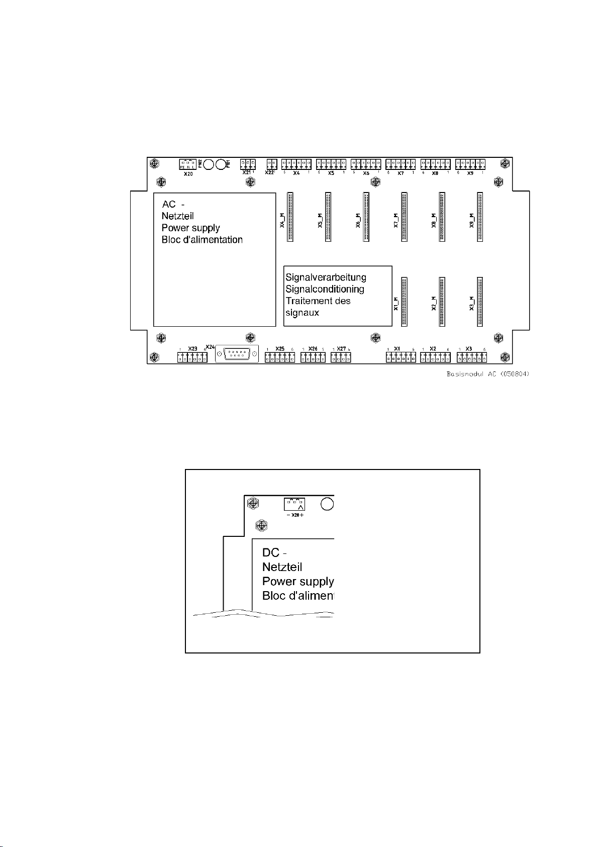
1.2.1 AC-board construction
1.2.2 DC-board construction
The DC board is identical to the AC board as far as the power supply and
power connections are concerned.
- 6 - C100584.002 Module Vers. 08 © VC-6000
TM
Compact monitor Nov. 2014
Page 63
BASE Module Part B VC-6000TM Compact monitor
1.3 Connection plugs on the Base Module
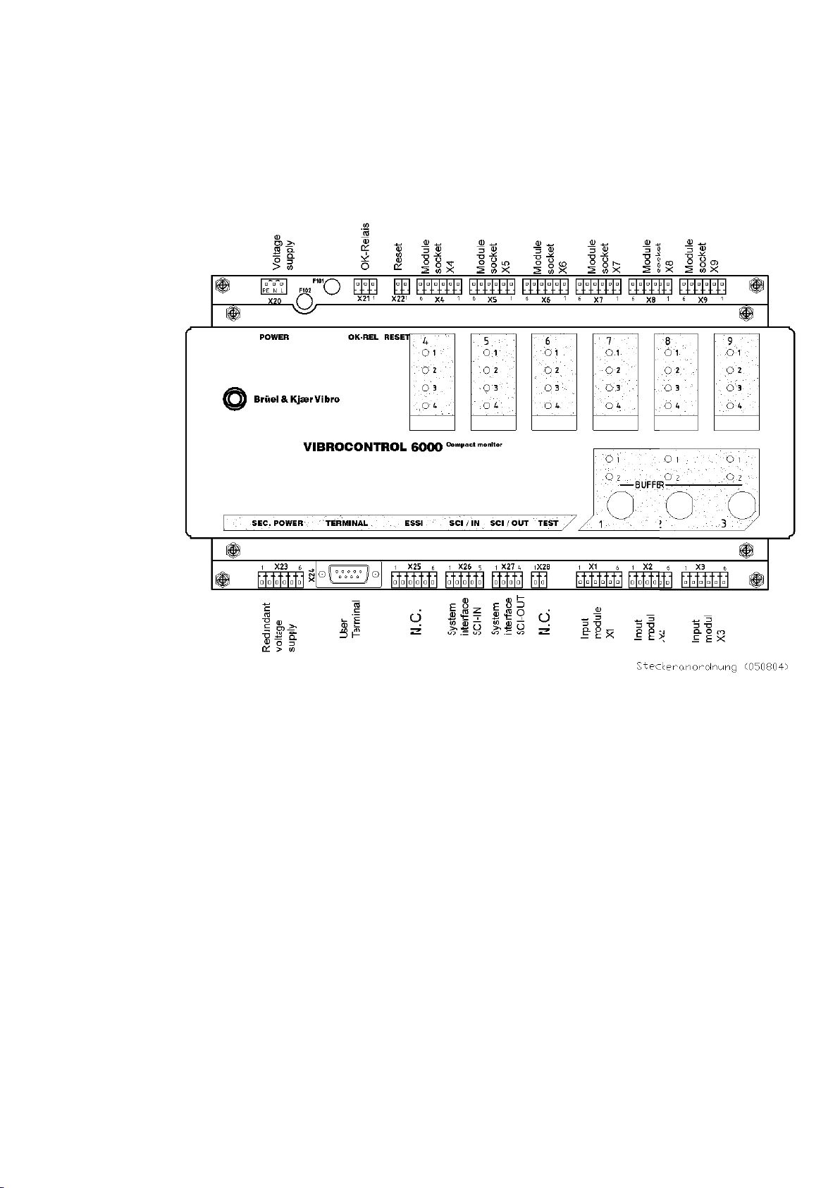
1.3.1 Overview
∗ Please note the corresponding plug layout for DC power on the DC Base board!
See the configuration sheet of the
VIBROCONTROL 6000 Compact monitor.
© VC-6000
TM
Compact monitor Nov, 2014 C100584.002 Module Vers. 08 - 7 -
Page 64
VC-6000TM Compact monitor Part B BASE Module
Yes
Yes
Yes
Yes
Yes
Yes
Yes
Yes
Yes
Yes
Yes
Yes
No
Yes
Yes
Yes
No
Yes
Yes
Yes
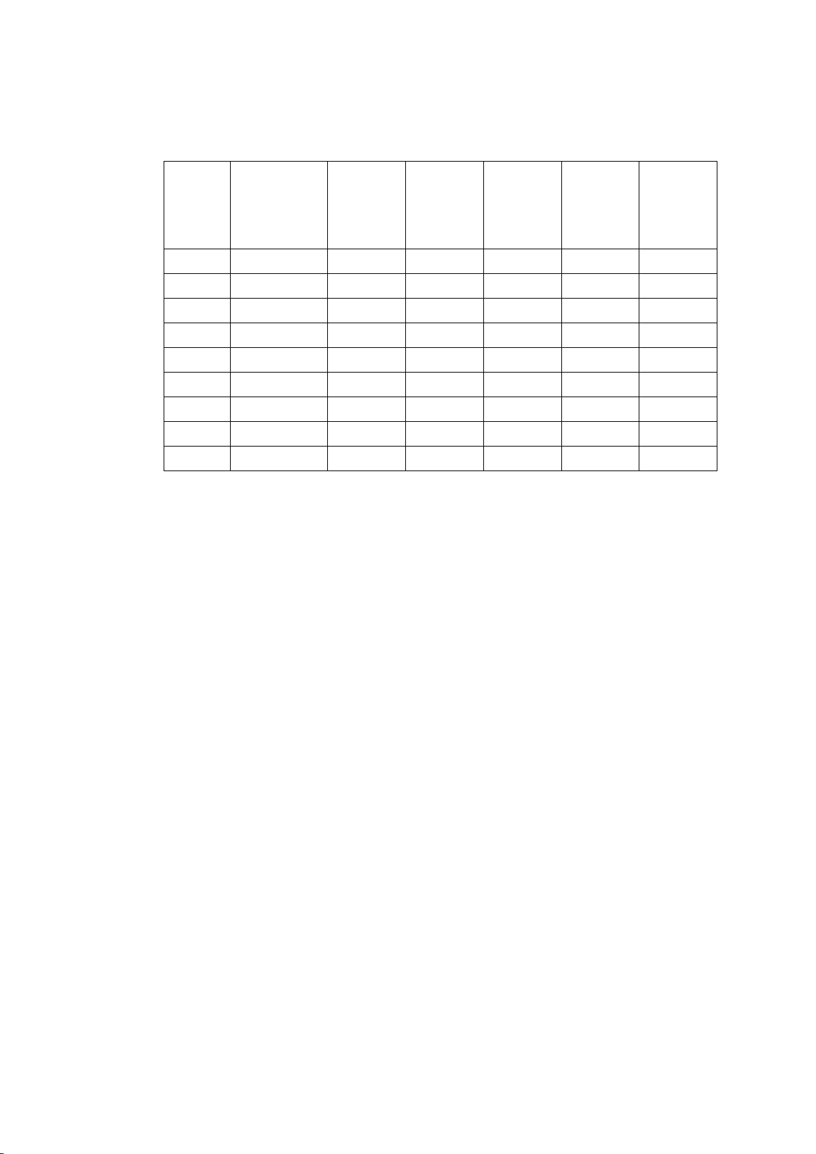
1.3.2 Socket position and assigned connection plug
Module
socket
no.
1 X1 Yes (Yes) (Yes) (Yes) (Yes)
2 X2 Yes Yes (Yes) (Yes) (Yes)
3 X3 Yes (Yes) (Yes) (Yes) (Yes)
4 X4 No No
5 X5 No No
6 X6 No No
7 X7 No No
8 X8 No
Assigned
connection
plug
Suitable
for
Sensor
Interface
Module
Suitable
for BCU-
CON
Suitable
for
DC-OUT
Module
Suitable
for
RELAY-
OUT
Module
Suitable
for
BINARY-
IN Module
9 X9 No
The connection plan for a
VIBROCONTROL 6000 Compact monitor is exclusively
determined through the hardware equipment in the module socket positions.
E.g. Socket position no. 1 contains a A-TIM-24 V → the terminal layout of
A-TIM-24 V is valid for plug X1, etc.
- 8 - C100584.002 Module Vers. 08 © VC-6000
TM
Compact monitor Nov. 2014
Page 65

BASE Module Part B VC-6000TM Compact monitor
1.4 The connections – their function and layout
1.4.1 Sensor Interface Module: Connections X1, X2 and X3
The socket positions X1_M, X2_M and X3_M belong to the connections X1
to X3.
These socket positions can be equipped with Sensor Interface Modules or
the 2-channel conditioner module for BCU.
The input modules for sensors receive the input signals from the sensors at
the connections associated with the appropriate socket positions.
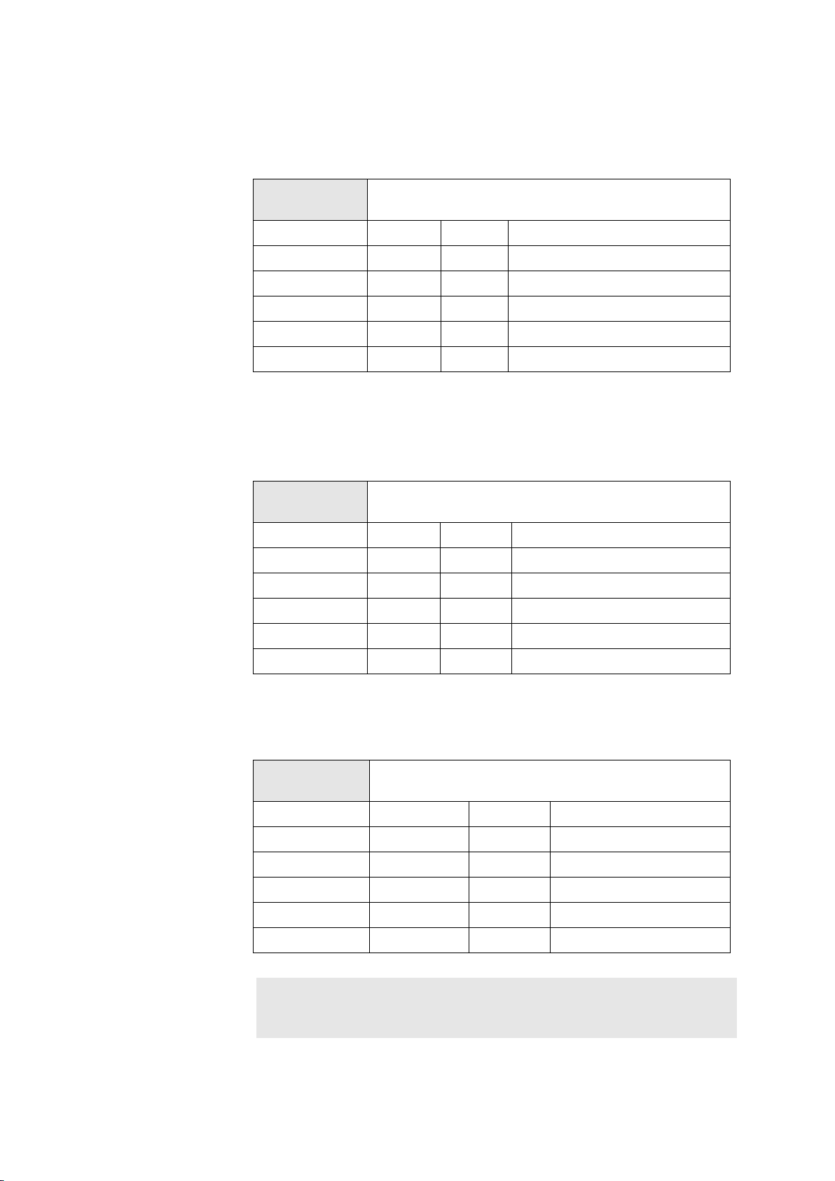
A-TIM (-24 V): Connection layout for 1-channel input module for
AS- sensor (e.g. AS-022, AS-030)
Connection
X1/X2/X3
Pin 1 0 V OUT Sensor power
A-TIM (-24 V)
Pin 2 -24 V OUT Sensor power
Pin 3 COM IN signal in (common)
Pin 4 SIG IN signal in (signal)
Pin 5 does not use
Pin 6 0 V OUT not occupied
A-TIM-CCS*: Connection layout for 1-channel input module for
AS- sensor (e.g. AS-062, 8325, 8327)
∗ CCS = constant current supply
Connection
X1/X2/X3
Pin 1 0 V OUT not occupied
Pin 2 -24 V OUT not occupied
Pin 3 COM IN signal in (common)
Pin 4 SIG IN signal in (signal + 8 mA current out)
Pin 5 does not use
A-TIM (CCS)
© VC-6000
Pin 6 0 V OUT not occupied
TM
Compact monitor Nov, 2014 C100584.002 Module Vers. 08 - 9 -
Page 66
VC-6000TM Compact monitor Part B BASE Module
V-TIM (8 Hz) & V-TIM (15 Hz): Connection layout for 1-channel
input module for VS-sensor
Connection
X1/X2/X3
Pin 1 does not use
Pin 2 does not use
Pin 3 COM IN signal in (common)
Pin 4 SIG IN signal in (signal)
Pin 5 does not use
Pin 6 does not use
V-TIM (8 Hz and 15 Hz)
D-TIM: Connection layout for 1-channel for input module for
displacement sensor (e.g. Sensors of the series SD-xxx, IN-xxx
and D-xxxx)
Connection
X1/X2/X3
D-TIM
Pin 1 0 V OUT does not use
Pin 2 -24 V OUT does not use
Pin 3 COM IN signal in (common)
Pin 4 SIG IN signal in (signal)
Pin 5 does not use
Pin 6 0 V OUT does not use
GP-TIM: Connection layout for 2-channel input module for
current/voltage
Connection
X1/X2/X3
Pin 1 Volt In A IN Voltage channel A
Pin 2 Curr In A IN Current channel A
Pin 3 COM A IN Common channel A
Pin 4 Volt In B IN Voltage channel B
Pin 5 Curr In B IN Current channel B
Pin 6 COM B IN Common channel B
GP-TIM
Note:
- 10 - C100584.002 Module Vers. 08 © VC-6000
Either two current inputs or two voltage inputs can be used at a GP-TIM. A
mixture of these input signal types is not possible !
TM
Compact monitor Nov. 2014
Page 67
BASE Module Part B VC-6000TM Compact monitor
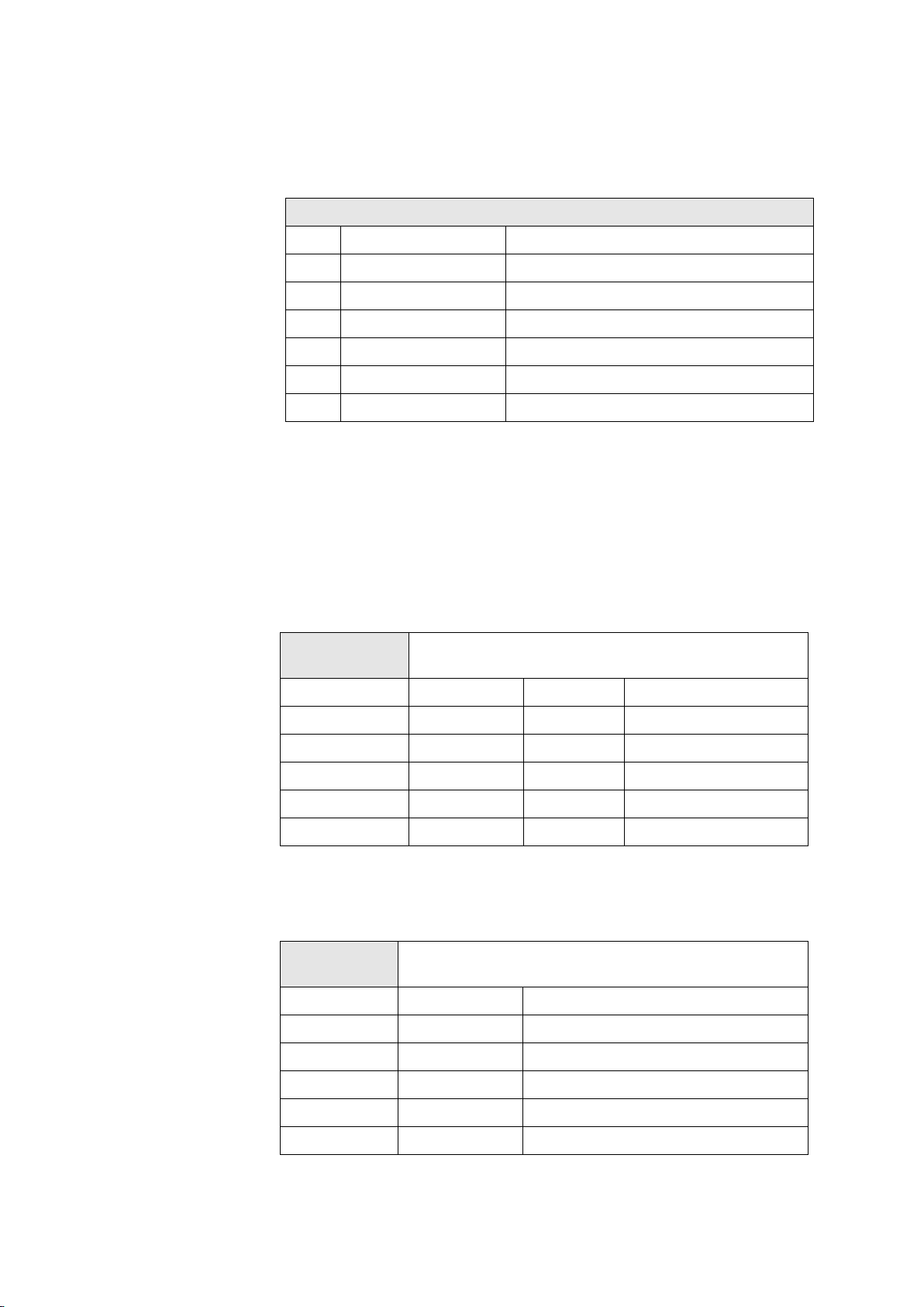
BINARY-IN: Connection layout for 3-channel input module for
binary status signals
BINARY-IN Pin-connection layout (X1 –X3)X4 to X9
PIN Signal Explanation
1 HI A Channel A input SIG (HIGH)
2 LO A Channel A input GND (LOW)
3 HI B Channel B input SIG (HIGH)
4 LO B Channel B input GND (LOW)
5 HI C Channel C input SIG (HIGH)
6 LO C Channel C input GND (LOW)
1.4.2 Output and supplementary modules: Connections X4 to X9
The socket positions X4_M to X9_M belong to the connections X4 to X9.
These socket positions can be equipped with Output modules (Relay and
DC out). The connection layout is dependent on the equipped module type.
DC-OUT (2-ch.): Connection layout for 2-channel output module
for current/voltage
Connection
X4 to X9
Pin 1 Volt In A OUT Voltage, channel A
Pin 2 Curr In A OUT Current, channel A
Pin 3 COM A OUT Common, channel A
Pin 4 Volt In B OUT Voltage, channel B
Pin 5 Curr In B OUT Current, channel B
Pin 6 COM B OUT Common, channel B
DC-OUT (2ch.)
RELAY-OUT (2-ch.): Connection layout for 2-channel Relay output module
Connection
X4 to X9
Pin 1 ARM RelA Arm, Relay A
RELAY-OUT (2ch.)
Pin layout in the de-energised condition
© VC-6000
Pin 2 NO RelA Normally-open contact, Relay A
Pin 3 NC RelA Normally-closed contact, Relay A
Pin 4 ARM RelB Arm, Relay B
Pin 5 NO RelB Normally-open contact, Relay B
Pin 6 NC RelB Normally-closed contact, Relay B
TM
Compact monitor Nov, 2014 C100584.002 Module Vers. 08 - 11 -
Page 68

VC-6000TM Compact monitor Part B BASE Module
1.4.3 System: Connections X20 to X27
The connections X20 to X27 are system connections, and their function and
connection layout is dependent on the hardware equipment.
1.4.3.1 Internal power supply: X20 – Power supply
The internal power supply of the Base Module is provided with power
through the connection X20.
According to the delivered Base Module a distinction must be made between
AC power and DCpower.
Connection
X20
Pin 1 L IN Live
Pin 2 N IN Neutral
Pin 3 PE IN Ground (Protective Earth)
Connection
X20
Power supply 230 V AC permissible power range:
90 ... 264 V AC / 50 ... 60 Hz
Power supply 24 V DC (48 V DC)
permissible power range 20 ... 75 V DC
Pin 1 20-75 V DC IN Plus (+)
Pin 2 free
Pin 3 0v IN Minus (-)
Caution!
Maximally 75 V smoothed DC voltage may be attached!
- 12 - C100584.002 Module Vers. 08 © VC-6000
TM
Compact monitor Nov. 2014
Page 69
BASE Module Part B VC-6000TM Compact monitor
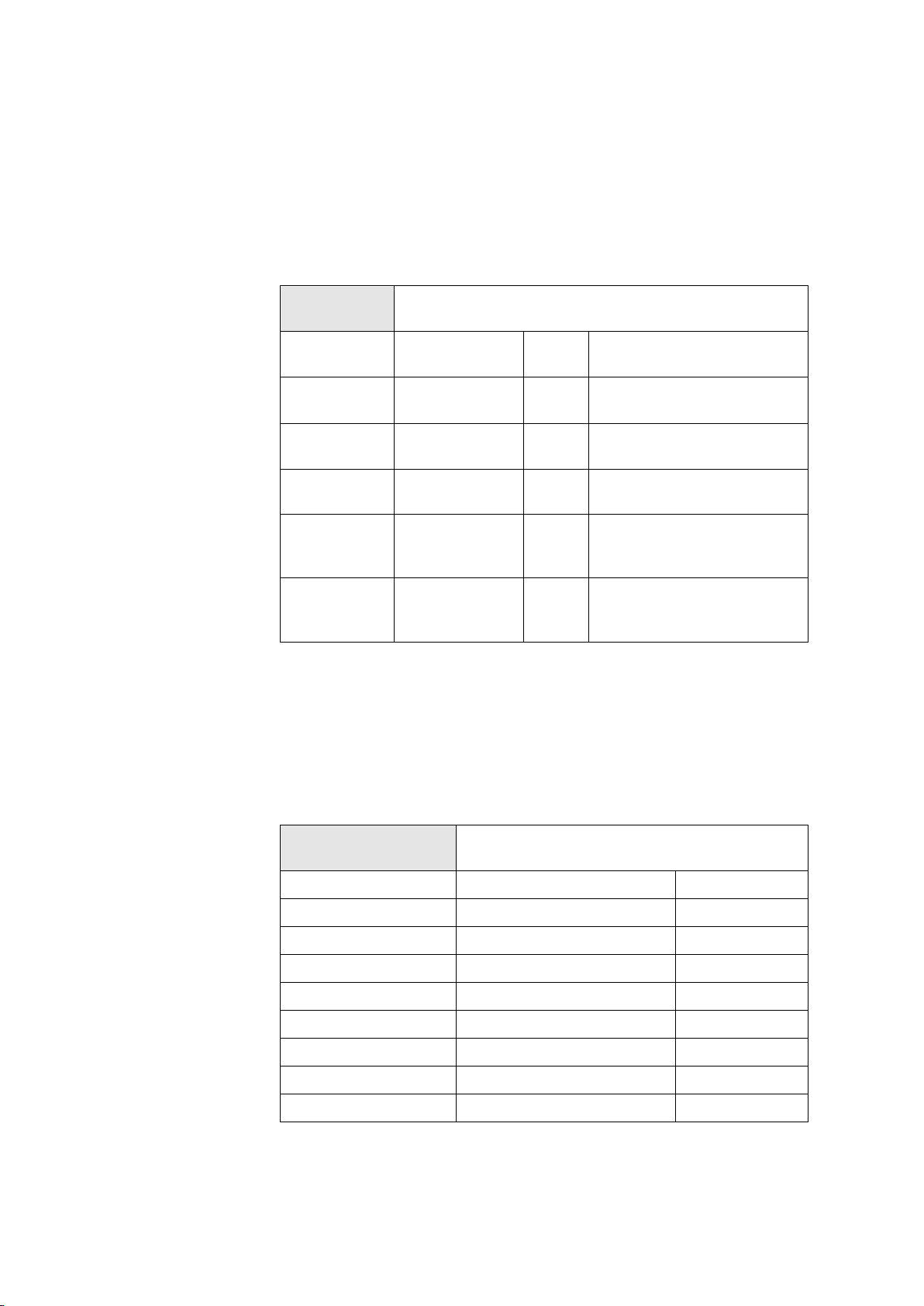
1.4.3.2 External power supply: X23 – Input for Redundant power supply
To increase the safety of a VIBROCONTROL 6000 Compact monitor against
power failure it is possible to connect a 2nd power supply (redundant). It
should be noted that only a power supply suitable for the power
requirements of the internal power of the VIBROCONTROL 6000 Compact
monitor should be used. This external power supply must provide all the
necessary irreversible DC secondary voltages.
Connection
X23
Pin 1 + 6,5 V DC IN + 6,5 V input for external
Pin 2 0 V IN 0 V reference potential
Pin 3 0 V IN 0 V reference potential
Pin 4 -27 V DC IN -27 V input for external
External power supply
power supply
secondary side
secondary side
power supply
Pin 5 Pwrfailure e1 IN Primary power failure at
Pin 6 Pwrfailure e2 IN Secondary power failure at
1.4.3.3 User Terminal: X24 – Local operation
The User-terminal is connected to the VIBROCONTROL 6000 Compact
monitor through this connection.
The User-terminal serves for local access to the
VIBROCONTROL 6000 Compact monitor menus. (→ Chapter: Operation of
the User-terminal).
Connection X24
(DSUB 9-pole socket)
Pin 1 + 5 V DC OUT
Pin 2 Module Clock OUT
Pin 3 0VD OUT
Pin 4 nLOAD OUT
User-terminal
external power supply
(binary signal)
external power supply
(binary signal)
© VC-6000
Pin 5 nOutEnable OUT
Pin 6 Not occupied
Pin 7 serDataToDisplay OUT
Pin 8 serDataFromDisplay IN
Pin 9 Not occupied
TM
Compact monitor Nov, 2014 C100584.002 Module Vers. 08 - 13 -
Page 70
VC-6000TM Compact monitor Part B BASE Module
1.4.3.4 OK-relay: X21 – Signalling of system interruptions
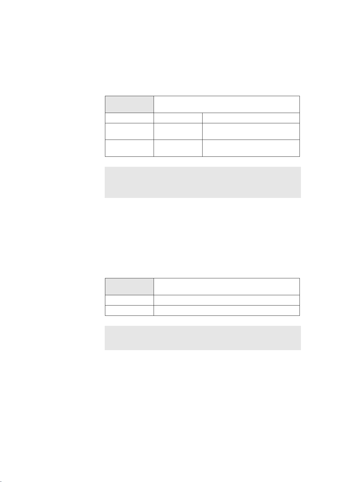
The OK-relay signals system events from the VIBROCONTROL 6000 Compact
(“OK” and “not OK”).
monitor
The potential-free contact of the OK-relay can be used to provide a signal to
peripheral electronic equipment.
Connection
X21
Pin 1 ARM Arm of the OK-relay
Pin 2 NC Normally-closed contact
Pin 3 NO Normally-open contact
OK - RELAY
Contact pin layout in normally-energised mode
(normally-energised status)
(normally-energised status)
Note:
A list of possible reasons for initiation of an OK fault is contained in section D
in the chapter on Instrument Operation. The Logbook function, which simultaneously records all events that occur, is described in the same chapter.
1.4.3.5 Remote reset: X22 – Binary input for a global reset
The Remote reset connection serves for a global reset of a
VIBROCONTROL 6000 Compact monitor by a binary signal. All events are
reset and all sensor OK faults and relays in the latching mode will be reset.
The Remote reset is activated when pins 1 and 2 of the connection X22 are
briefly short-circuited; e.g. by a push-button or a bridge.
A bridge can permanently connect the terminals. The Reset function then
operates when the bridge is opened and then closed again (edge-triggered).
Connection
X22
Pin 1 Input
Pin 2 3,3 V
Note:
Limit setpoint violations that still exist will not be reset by the Remote reset.
An existing limit setpoint violation will automatically be signalled again.
Remote Reset
- 14 - C100584.002 Module Vers. 08 © VC-6000
TM
Compact monitor Nov. 2014
Page 71
BASE Module Part B VC-6000TM Compact monitor
1.4.3.6 System interface: X25 – ESSI
This interface is reserved for future extensions.
1.4.3.7 System-interface: X26 and X27 – SCI-IN / SCI-OUT
SCI stands for Serial Communication Interface
These two connections allow, in combination with a suitable converter
(AC-5003), a serial communication to a PC (RS-232 interface) or a
connection to a TCP/IP network through a Gateway (AC-5004). This
communication is required, e.g. for a firmware download or to connect a
VIBROCONTROL 6000 Compact monitor with an OPC-server (OPC DAserver – Type 7131).
Connection
X26
Pin 1 OUT Wire back extension
Pin 2 RXD IN Receive data
Pin 3 0 VD OUT Ground
SCI IN (Serial communication interface)
Pin 4 SCLK IN Clock In
Pin 5 5 VD OUT 5 V supply
Connection
X27
Pin 1 OUT Wire back extension
Pin 2 TXD OUT Transmit data
Pin 3 0 VD OUT Ground
Pin 4 LOAD OUT Low for boot from SCI
SCI OUT (Serial communication interface)
(download)
Note:
For more detailed information about the connection of the converter of the
Gateway and the OPC DA-server – Type 7131 please use the corresponding product documentation.
© VC-6000
TM
Compact monitor Nov, 2014 C100584.002 Module Vers. 08 - 15 -
Page 72
VC-6000TM Compact monitor Part B BASE Module
1.5 Technical data
1.5.1 Electrical power supply
AC power supply
Input voltage range 90 ... 264 V AC
Frequency range 50 / 60 Hz
Maximum power consumption 40 VA
LED power supply monitor Green = OK, OFF = Interruption
Instrument fuses (F101, F102) T2A IEC 127
Size 5 x 20 mm
Note:
The PE-connection is attached to the instrument housing!
DC power supply
Input voltage range 20 ... 75 V DC
Maximum power consumption 40 VA
Instrument protection (F101) T2A IEC 60127
Type 5 x 20 mm
LED power supply monitor Green = OK; OFF = Interruption
Caution!
Maximally 75 V smoothed DC voltage may be attached!
Note:
The PE-connection can be attached at connection X28!
1.5.2 Mechanical execution
Socket positions
No. of socket positions (total) 9 (X1_M to X9_M)
No. of socket positions for input modules 3 (X1_M to X3_M)
No. of socket positions for output modules 6 (X4_M to X9_M)
- 16 - C100584.002 Module Vers. 08 © VC-6000
TM
Compact monitor Nov. 2014
Page 73
BASE Module Part B VC-6000TM Compact monitor
1.5.3 System
System function
Processor DSP Type 56309@ 98,304 MHz
Memory 16 Mbit Flash
Measurement and Monitoring function
A/D converter 6-channel with 14 bit resolution
Sampling frequency 64 kHz per channel
Signal processing all channels continuous
Internal cycle time 5 ms
Minimum reaction time 5 ms + measuring time
Specialities Hot-swap capability for module exchange
OK-relay
Maximum contact voltage < 50 V
Maximum current < 500 mA
Minimum current 10 µA
Minimum voltage 10 mV
Caution!
The maximum values must not be exceeded. Take precautions for inductive
or capacitive loads.
OK-LED Green = OK; OFF = System interruption
Note:
The OK-LED gives signals for various system conditions through a flashing
pattern. For a corresponding description consult section D, chapter 12.4.
© VC-6000
TM
Compact monitor Nov, 2014 C100584.002 Module Vers. 08 - 17 -
Page 74
VC-6000TM Compact monitor Part B 1-channel input module for acceleration sensors
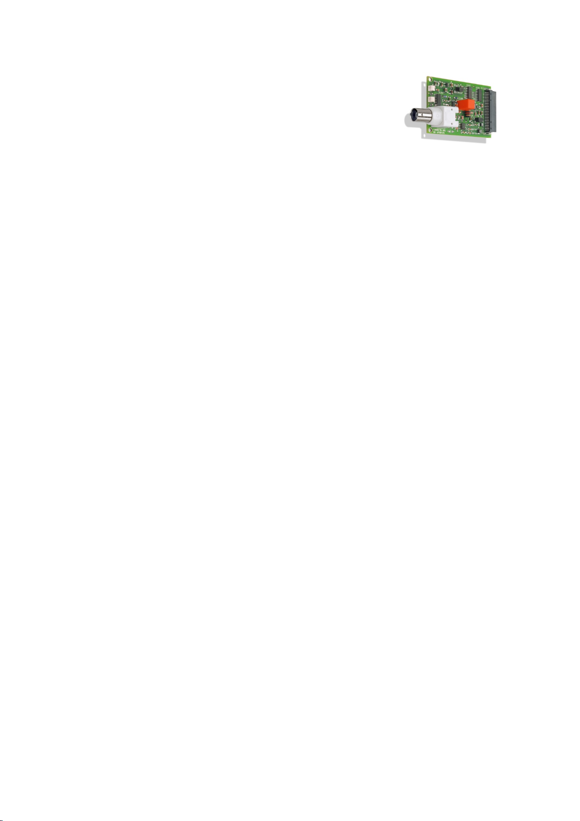
2 1-channel input module for
acceleration sensors
2.1 Function
♦ The input module for acceleration sensors, abbreviated to A-TIM
(Acceleration Transducer Interface Module), is separately laid out for
connection of a sensor.
♦ There are two executions for an A-TIM, distinguished by the type of
sensor. As a result there are various requirements for the sensor that
will be connected:
◊ A-TIM (-24 V) for connection of sensors with a power requirement
of -24 V/max. 30 mA.
◊ A-TIM (CCS) for connection of sensors with a constant-current
power requirement (max. 8 mA).
♦ Input modules are managed internally in the instrument through a
Sensor block (Firmware), i.e. an A-TIM and Sensor block together form
a physical interface between the
the outside world. The measured signal from the sensor is acquired and
made available to the signal path for further processing and
assessment.
VIBROCONTROL 6000 Compact monitor and
♦ An A-TIM combines the following hardware functions:
• Differential input amplifier
• Signal amplifier
• Switchable integrator
• De-coupled buffered output (BNC socket at front)
for sensor output signal
• Sensor power supply
• LED signalling
- 18 - C100584.002 Module Vers. 08 © VC-6000
TM
Compact monitor Nov. 2014
Page 75

1-channel input module for acceleration sensors Part B VC-6000TM Compact monitor
2.2 Signal path
♦ The input to an A-TIM is a coupled differential input amplifier. The output
signal of the input amplifier is passed on to two separate signal paths.
Each path is assigned to an A/D converter channel.
♦ DC-signal path (DC coupled processing path)
This signal path has continuous access to the entire raw signal,
including the available DC part of the signal.
In this path also the DC-operating point (sensor passive voltage)
resulting from the sensor power supply is acquired and monitored
(sensor OK-monitoring).
An error-free measurement chain is signalled through a green OK
LED on the 1-channel input module for AS- sensors.
♦ AC-signal path (AC coupled processing path)
This signal path has access only to the AC part of the raw sensor
signal. The dynamics of the processing can thus be used
completely for the vibration measurement. As a result the
acceleration signal from a connected sensor can be evaluated with
maximum resolution and accuracy.
The input range of the AC signal path is continuously monitored for
signal over-ranging. W hen over-ranging of an A/D converter occurs
this is signalled by a red LED on the front of the A-TIM.
© VC-6000
TM
Compact monitor Nov, 2014 C100584.002 Module Vers. 08 - 19 -
Page 76

VC-6000TM Compact monitor Part B 1-channel input module for acceleration sensors
2.3 Technical data
2.3.1 Electrical properties
Input:
Input voltage range -21,5 V ... + 2,5 V
Frequency range of input signal > 0 ... 50 kHz
Input impedance 200 kΩ
Sensor Sensitivity analogue adjustable
Amplification in 8 steps
from 1 ... 80 (6 0,75 %)
with integration (6 2,75 %)
Buffered output:
Output voltage range min. -21 V ...+ 2 V
Frequency range of output signal > 0 ... 50 kHz
Output load min. 10 kΩ
Amplification 1 (6 2 %)
Phase shift (-24 V) 20 kHz < 15°
50 kHz < 35°
Phase shift (CCS) 20 kHz 180° + < 15°
50 kHz 180° + < 35°
Short-circuit proof Yes
CCS Sensor power:
Supply current 8 mA (SIGNAL and COM)
-24 V Sensor power:
Supply voltage -24 V DC
Supply current Max. 30 mA
- 20 - C100584.002 Module Vers. 08 © VC-6000
TM
Compact monitor Nov. 2014
Page 77
1-channel input module for acceleration sensors Part B VC-6000TM Compact monitor
2.3.2 Equipment and signalling
♦ Possible socket positions on the Base Module:
X1_M X2_M X3_M
♦ Connection plugs on the Base Module (dependent on the selected
socket position): X1 X2 X3
A-TIM (-24 V) Pin layout connections X1/X2/X3
PIN Signal Explanation
1 0 V Sensor power supply
2 -24 V Sensor power supply
3 COM Sensor signal reference potential
4 SIG Sensor signal
5 Not connected
6 0 V 0 V
A-TIM (CCS) Pin layout connections X1/X2/X3
PIN Signal Explanation
1 0 V OUT
2 -24 V OUT
3 COM
4 SIG
-) Sensor signal reference potential
(
+) Sensor signal and 8 mA constant
(
current
5
6 0 V OUT
© VC-6000
TM
Compact monitor Nov, 2014 C100584.002 Module Vers. 08 - 21 -
Page 78
VC-6000TM Compact monitor Part B 1-channel input module for acceleration sensors
♦ LED OVERLOAD (RD)
The red LED provides information about the condition of the A/D
converter. This will provide information whether an over-range exists or
has existed through the input signal or whether everything is in order.
♦ OK-LED (GN)
The green LED signals the OK status of the sensor. If there is an OKfault the LED will be extinguished. The OK monitoring checks the
status of the sensor signal (including the DC value) with reference to the
OK-voltage window. This OK-window (upper and lower limits) can be set
up using the User Terminal.
An OK-fault exists as soon as a single sampled value is found to lie
outside the set OK-window range.
LED Status Explanation
Red Off No over-range
Red Flashing at 2 Hz An over-range exists and has not
yet been confirmed through the
dialogue
Red Flashing at 0,5 Hz Only with parameter OK latching:
No over-range currently exists;
an earlier over-range not yet
confirmed through the dialogue.
Red On Continuous over-range; has
been confirmed through the
OVERLOAD LED
dialogue
Green Off Continuous OK fault; has been
confirmed through the dialogue
Green Flashing at 2 Hz Sensor OK fault; not yet
confirmed through the dialogue
Green Flashing at 0,5 Hz Only with OK latching parameter:
No sensor OK fault currently
exists, an earlier fault not yet
confirmed through the dialogue
OK-LED
Green On No sensor OK fault
- 22 - C100584.002 Module Vers. 08 © VC-6000
TM
Compact monitor Nov. 2014
Page 79

1-channel input module for vibration velocity sensors Part B VC-6000TM Compact monitor
3 1-channel input module for vibration
velocity sensors
3.1 Function
♦ The input module for vibration velocity sensors, abbreviated to V-TIM
(Velocity Transducer Interface Module) is laid out for the connection of a
sensor.
♦ There are two executions for a V-TIM, distinguished by built-in linea-
risation of the frequency response
• V-TIM 8 Hz for vibration velocity sensors with a resonance at 8 Hz
(e.g. Brüel & Kjær Vibro sensors VS-068, VS-069).
• V-TIM 15 Hz for vibration velocity sensors with a resonance at
15 Hz (e.g. Brüel & Kjær Vibro sensors VS-077, VS-079).
♦ The input module is managed internally by a Sensor block (Firmware),
i.e. V-TIM and Sensor block together form a physical interface between
the VIBROCONTROL 6000 Compact monitor
The measured signal from the connected sensor is acquired and
provided to the signal path for further processing and evaluation.
and the outside world.
♦ A V-TIM combines the following hardware functions:
3.2 Signal path
♦ The input of a V-TIM is a DC coupled differential input amplifier. The
• Differential input amplifier
• Signal amplifier
• Frequency response linearisation for very low frequencies
• De-coupled buffered output (front BNC socket)
for sensor output signal
• Auxiliary voltage for cable damage monitoring
• LED signalling
output signal of the input amplifier is passed on to two separate signal
paths. Each path is assigned to an A/D converter channel.
© VC-6000
TM
Compact monitor Nov, 2014 C100584.002 Module Vers. 08 - 23 -
Page 80

VC-6000TM Compact monitor Part B 1-channel input module for vibration velocity sensors
♦ DC-Signal path (DC coupled processing path)
This signal path has continuous access to the entire raw signal,
including the available DC voltage part of the signal.
In this path also the DC-operating point (sensor passive voltage)
resulting from the sensor power supply is acquired and monitored
(sensor OK-monitoring). An error-free measurement chain is
signalled through an OK LED on the front panel of the V-TIM.
♦ AC-path (AC coupled processing path)
This signal path has access only to the AC part of the raw sensor
signal. The dynamics of the processing can thus be used
completely for the vibration measurement. As a result the velocity
signal from a connected sensor can be evaluated with maximum
resolution and accuracy.
The input range of the AC signal path is continuously monitored for
signal over-ranging. W hen over-ranging of an A/D converter occurs
this is signalled by a red LED on the front of the V-TIM.
3.3 Technical data
3.3.1 Electrical properties
Input:
Input voltage range -21,5 V ... + 2,5 V
Frequency range of input signal > 0 ... ≥ 20 kHz
Input impedance 50 kΩ
Settling time ca. 45 s
Sensor Sensitivity step adjustable
Amplification in 8 steps from 1 ... 80
(6 0,75 %)
Buffered output:
Output voltage range min. -21 V ...+ 2 V
Frequency range of output signal > 0 ... > 10 kHz
Output load min. 10 kΩ
Amplification 1 (6 2 %)
Phase shift (8 Hz) 20 kHz < 15°
50 kHz < 35°
Phase shift (15 Hz) 20 kHz 180° + < 15°
50 kHz 180° + < 35°
Short-circuit proof Yes
- 24 - C100584.002 Module Vers. 08 © VC-6000
TM
Compact monitor Nov. 2014
Page 81
1-channel input module for vibration velocity sensors Part B VC-6000TM Compact monitor
3.3.2 Equipment and signalling
♦ Possible socket positions on the Base Module X1_M X2_M X3_M
♦ Corresponding connections on Base Module X1 X2 X3
♦ Connection layout with a V-TIM
V-TIM Pin layout connections X1/X2/X3
PIN Signal Explanation
1
2
3 COM Sensor signal reference potential
4 SIG Sensor signal
5
6
♦ LED OVERLOAD (RD)
The red LED provides information about the condition of the A/D
converter. This will provide information whether an over-range exists or
has existed through the input signal or whether everything is in order.
The red LED signals although, if the attached sensor is exposed to an
inadmissibly large swinging displacement amplitude (sensor overload).
♦ OK-LED (GN)
The green LED signals the OK status of the sensor. If there is an OKfault the LED will be extinguished. The OK monitoring checks the
status of the sensor signal (including the DC value) with reference to the
OK-voltage window. This OK-window (upper and lower limits) can be set
up using the User Terminal.
An OK-fault exists as soon as a single sampled value is found to lie
outside the set OK-window range.
© VC-6000
TM
Compact monitor Nov, 2014 C100584.002 Module Vers. 08 - 25 -
Page 82
VC-6000TM Compact monitor Part B 1-channel input module for vibration velocity sensors
LED Status Explanation
Red Off No over-range
Red Flashing at 2 Hz An over-range exists; not yet
confirmed through the dialogue
Red Flashing at 0,5 Hz Only with OK latching parameter:
No existing over-range; an earlier
over-range not yet confirmed
through the dialogue
Red On Continuous over-range exists;
has been confirmed through the
OVERLOAD LED
dialogue
Green Off Continuous OK fault exists; has
been confirmed through the
dialogue
Green Flashing at 2 Hz Sensor OK fault not yet
confirmed through the dialogue
Green Flashing at 0,5 Hz Only with the OK latching
parameter:
No OK fault currently exists; an
earlier OK fault not yet been
confirmed through the dialogue
OK-LED
Green On No sensor OK fault
- 26 - C100584.002 Module Vers. 08 © VC-6000
TM
Compact monitor Nov. 2014
Page 83

1-channel input module for displacement sensors Part B VC-6000TM Compact monitor
4 1-channel input module for
displacement sensors
4.1 Function
♦ The input module for displacement sensors, abbreviated to D-TIM
(Displacement Transducer Interface Module) is laid out for connection of
a displacement sensor.
Sensors of the series SD-xxx, IN-xxx and DS-xxx from the Brüel & Kjær
Vibro delivery program can be connected.
♦ The input module is internally managed through a Sensor block
(Firmware), i.e. the D-TIM and Sensor block together form a physical
interface between the VIBROCONTROL 6000 Compact monitor
outside world. The signal from the connected sensor is acquired and
made available to the signal path for further processing and evaluation.
♦ A D-TIM combines the following hardware functions:
• Differential input amplifier
and the
4.2 Signal path
♦ The input of a D-TIM is a DC coupled differential input amplifier. The
♦ DC-signal path (DC coupled processing path)
♦ AC-path (AC coupled processing path)
• Signal amplifier
• De-coupled buffered output (front BNC socket)
for sensor output signal
• Sensor power supply
• LED signalling
output signal from the input amplifier is passed on to two separate signal
paths. Each signal path is assigned an A/D converter channel.
This signal path has continuous access to the entire raw signal,
including the available DC part of the signal.
In this path also the DC-operating point (sensor passive voltage)
resulting from the sensor power supply is acquired and monitored
(sensor OK-monitoring). An error-free measurement chain is
signalled through an OK LED on the front panel of the D-TIM.
This signal path has access only to the AC part of the raw sensor
signal. The dynamics of the processing can thus be used
completely for the vibration measurement. As a result the displacement signal from a connected sensor can be evaluated with
maximum resolution and accuracy.
© VC-6000
The input range of the AC signal path is continuously monitored for
signal over-ranging. W hen over-ranging of an A/D converter occurs
this is signalled by a red LED on the front of the D-TIM.
TM
Compact monitor Nov, 2014 C100584.002 Module Vers. 08 - 27 -
Page 84
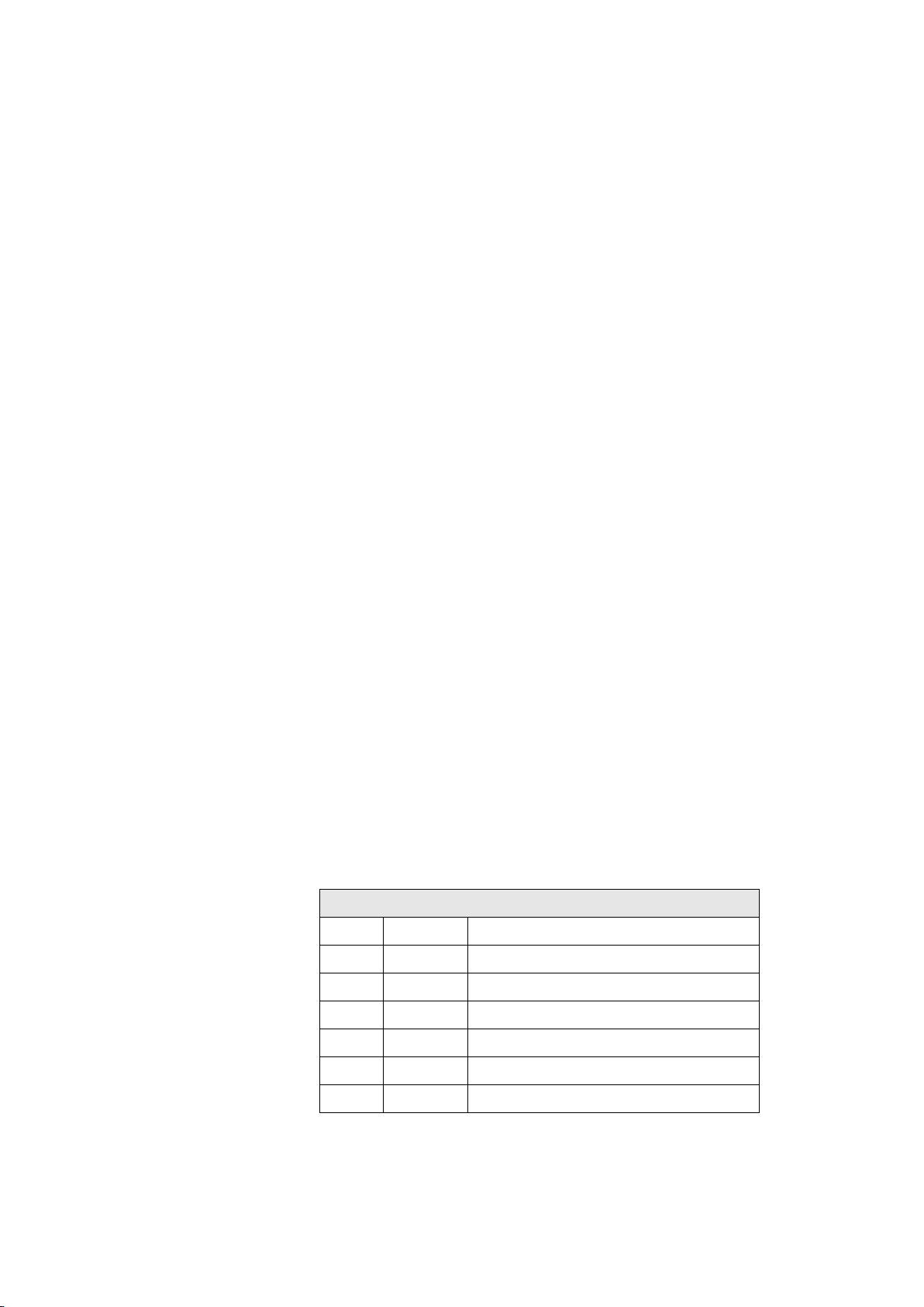
VC-6000TM Compact monitor Part B 1-channel input module for displacement sensors
4.3 Technical data
4.3.1 Electrical properties
Input:
Input voltage range -21,5 V ... + 2,5 V
Frequency range of input signal > 0 ... 50 kHz
Input impedance 200 kΩ
Sensor Sensitivity analogue adjustable
Amplification in 8 steps from 1 ... 80
(6 0,75 %)
Buffered output:
Output voltage range min. -21 V ...+ 2 V
Frequency range of output signal > 0 ... 50 kHz
Output load min. 10 kΩ
Amplification 1 (6 2 %)
Phase shift 20 kHz < 15°
50 kHz < 35°
Short-circuit proof Yes
Sensor power supply:
Power supply - 24 V DC
Current consumption max. 30 mA
4.3.2 Equipment and signalling
♦ Possible socket positions on the Base Module X1_M X2_M X3_M
♦ Corresponding connections on the Base Module X1 X2 X3
♦ Connection layout with a D-TIM
S-SIM Pin layout connection X1/X2/X3
PIN Signal Explanation
1 0 V Sensor power supply
2 -24 V Sensor power supply
3 COM Sensor signal reference potential
4 SIG Sensor signal
5 Not connected
6 0 V 0 V
- 28 - C100584.002 Module Vers. 08 © VC-6000
TM
Compact monitor Nov. 2014
Page 85
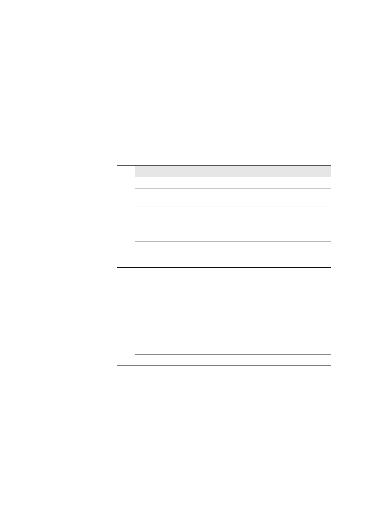
1-channel input module for displacement sensors Part B VC-6000TM Compact monitor
♦ LED OVERLOAD (RD)
The red LED provides information about the condition of the A/D
converter. This will provide information whether an over-range exists or
has existed through the input signal or whether everything is in order.
♦ OK-LED (GN)
The green LED signals the OK status of the sensor. If there is an OKfault the LED will be extinguished. The OK monitoring checks the
status of the sensor signal (including the DC value) with reference to the
OK-voltage window. This OK-window (upper and lower limits) can be set
up using the User Terminal.
An OK-fault exists as soon as a single sampled value is found to lie
outside the set OK-window range.
LED Status Explanation
Red Off No over-range
Red Flashing at 2 Hz An over-range exists; not yet
confirmed through the dialogue
Red Flashing at 0,5 Hz Only with OK latching parameter:
No over-range currently exists;
an earlier over-range not yet
confirmed through the dialogue
Red On Continuous over-range exists;
has been confirmed through the
OVERLOAD LED
dialogue
Green Off Continuous sensor OK fault
exists; has been confirmed
through the dialogue
Green Flashing at 2 Hz Sensor OK fault exists; not yet
confirmed through the dialogue
Green Flashing at 0,5 Hz Only with OK latching:
No OK fault currently exists; an
earlier fault not yet confirmed
through the dialogue
OK-LED
Green On No sensor OK fault
© VC-6000
TM
Compact monitor Nov, 2014 C100584.002 Module Vers. 08 - 29 -
Page 86
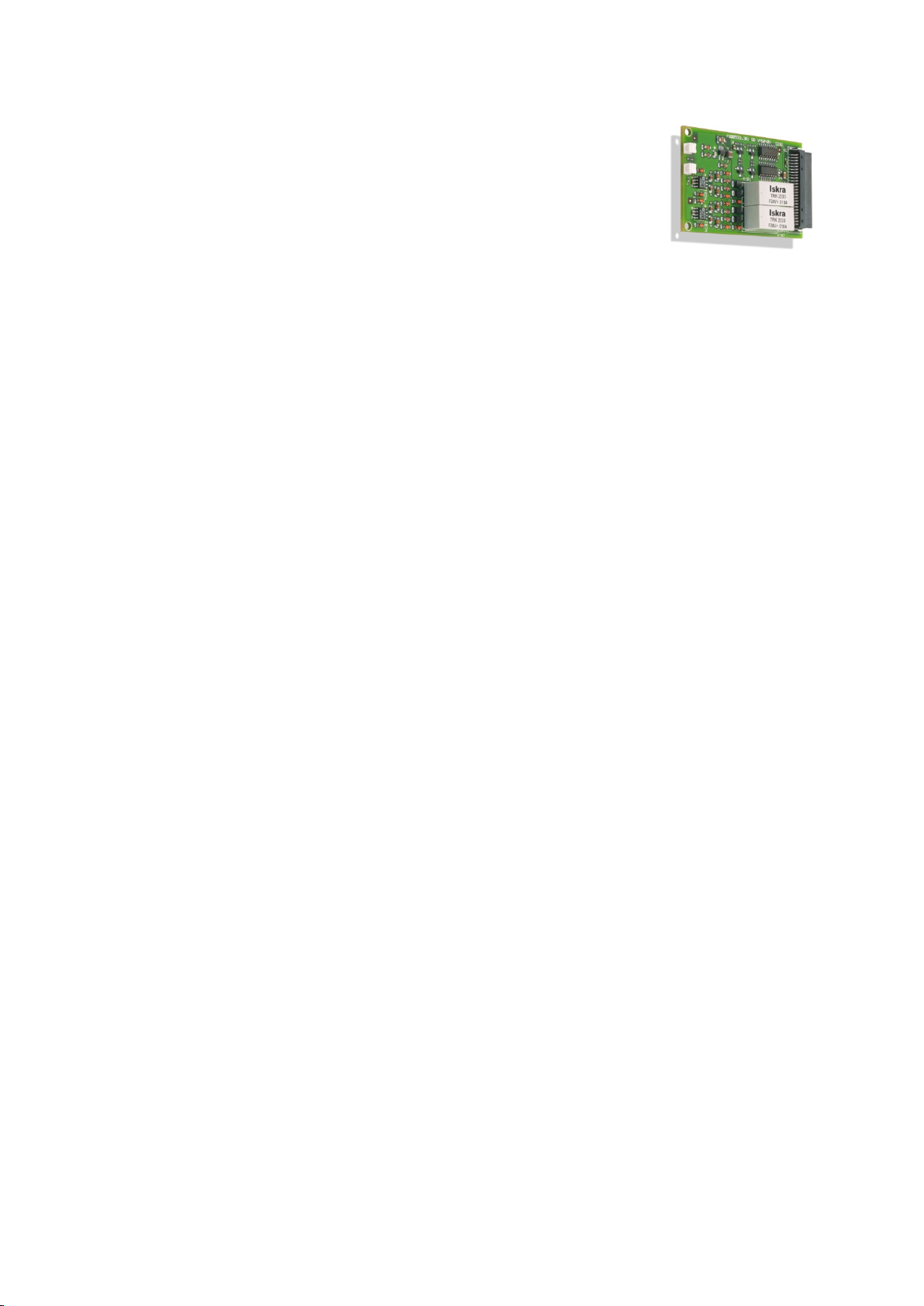
VC-6000TM Compact monitor Part B 2-channel input module for current / voltage
5 2-channel input module for current /
voltage
5.1 Function
♦ The input module for general current and
voltage signals, abbreviated to GP-TIM (General Purpose Transducer
Interface Module) is laid out for two measuring channels.
♦ Input signals of the type DC current (e.g. 4 - 20 mA), DC voltage
(e.g. 0 - 10 V), or dynamic voltage signals (-15 to +15 V) can be
processed. Selection of the desired input signal is done per channel
through the corresponding connection layout and the matching configuration through the dialogue with the User-Terminal.
♦ A GP-TIM has no sensor power available, i.e. all input signals must be
active signals.
♦ The input module is managed internally through a Sensor(A/B) block
(Firmware), i.e. GP-TIM and Sensor(A/B) block together form a physical
interface between the VIBROCONTROL 6000 Compact monitor and the
outside world. The measured signal from the connected sensor is
acquired and made available to the signal path for further processing
and evaluation.
♦ A GP-TIM combines the following hardware functions:
• Diffential input amplifier
• Input selection switch
• Signal amplifier
• LED signalling
5.2 Technical data
5.2.1 Electrical properties
Input:
Voltage range -14 V ... + 14 V
Current range -30 mA … + 30 mA
Frequency range of input signal > 0 ... 50 kHz
Input impedance 200 kΩ (with voltage)
Working resistance 100 Ω (with current)
Sensor Sensitivity analogue adjustable
Amplification 1 (6 1 %)
- 30 - C100584.002 Module Vers. 08 © VC-6000
TM
Compact monitor Nov. 2014
Page 87
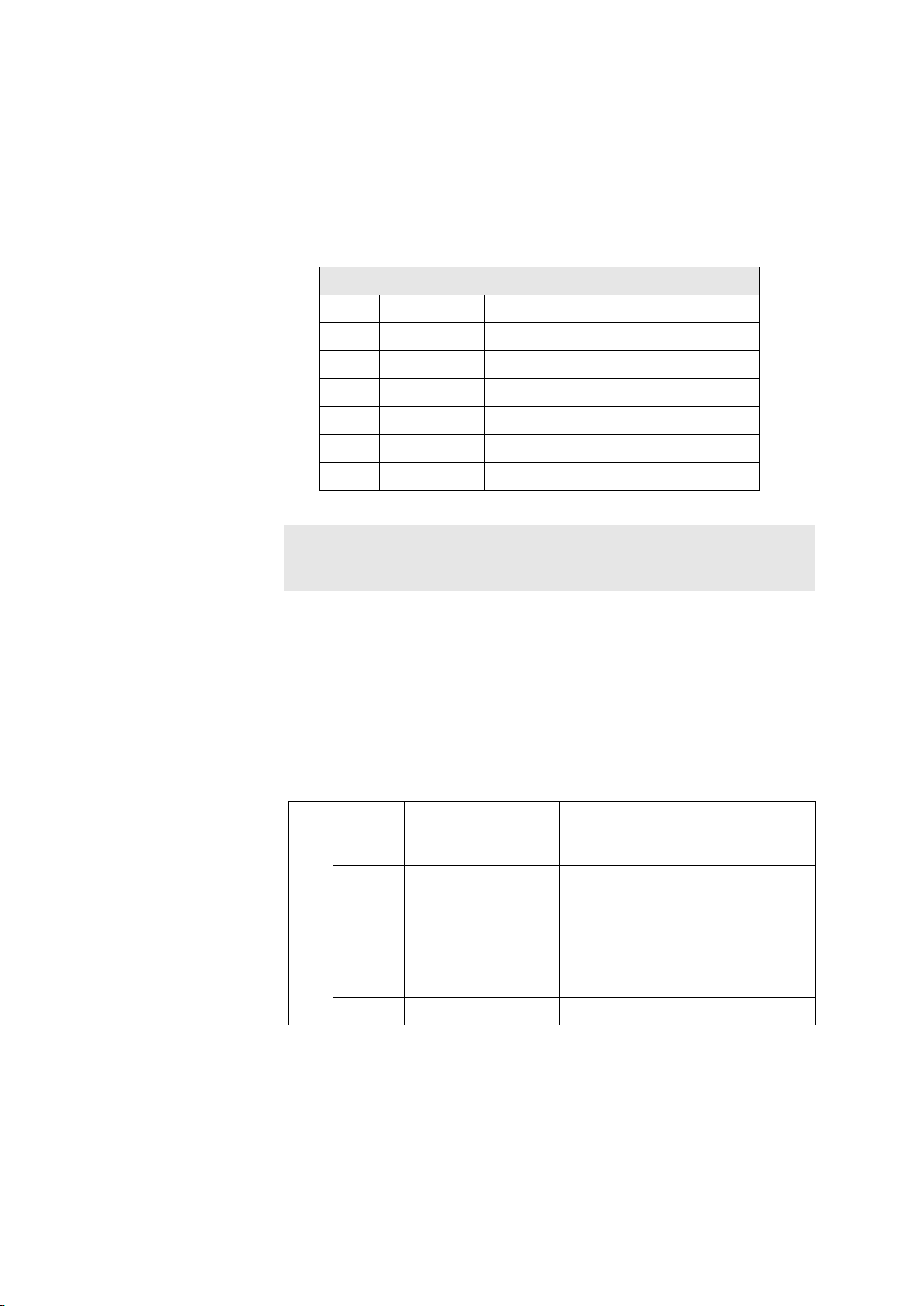
2-channel input module for current / voltage Part B VC-6000TM Compact monitor
5.2.2 Equipment and signalling
♦ Possible socket positions on the Base Module X1_M X2_M X3_M
♦ Connection plugs on the Base Module X1 X2 X3
♦ Connection plug layout of a GP-TIM
GP-TIM Pin layout connections X1/X2/X3
PIN Signal Explanation
1 Volt in A Voltage input, channel A
2 Curr in A Current input, channel A
3 COM A Reference potential, channel A
4 Volt in B Voltage input, channel B
5 Curr B Current input, channel B
6 COM B Reference potential, channel B
Note:
Either two current inputs or two voltage inputs can be used at one
GP-TIM. A mixture of these input signal types is not possible !
♦ OK-LED (GN)
The green LED signals the OK status of the sensor. If there is an OKfault the LED will be extinguished. The OK monitoring checks the
status of the sensor signal (including the DC value) with reference to the
OK-voltage window. This OK-window (upper and lower limits) can be set
up using the User Terminal.
An OK-fault exists as soon as a single sampled value is found to lie
outside the set OK-window range.
Green Off Continuous sensor OK fault
exists; has been confirmed
through the dialogue
Green Flashing at 2 Hz Sensor OK fault exists; not yet
confirmed through the dialogue
Green Flashing at 0,5 Hz Only with OK latching:
No OK fault currently exists; an
earlier fault not yet confirmed
through the dialogue
© VC-6000
OK-LED
Green On No sensor OK fault
TM
Compact monitor Nov, 2014 C100584.002 Module Vers. 08 - 31 -
Page 88
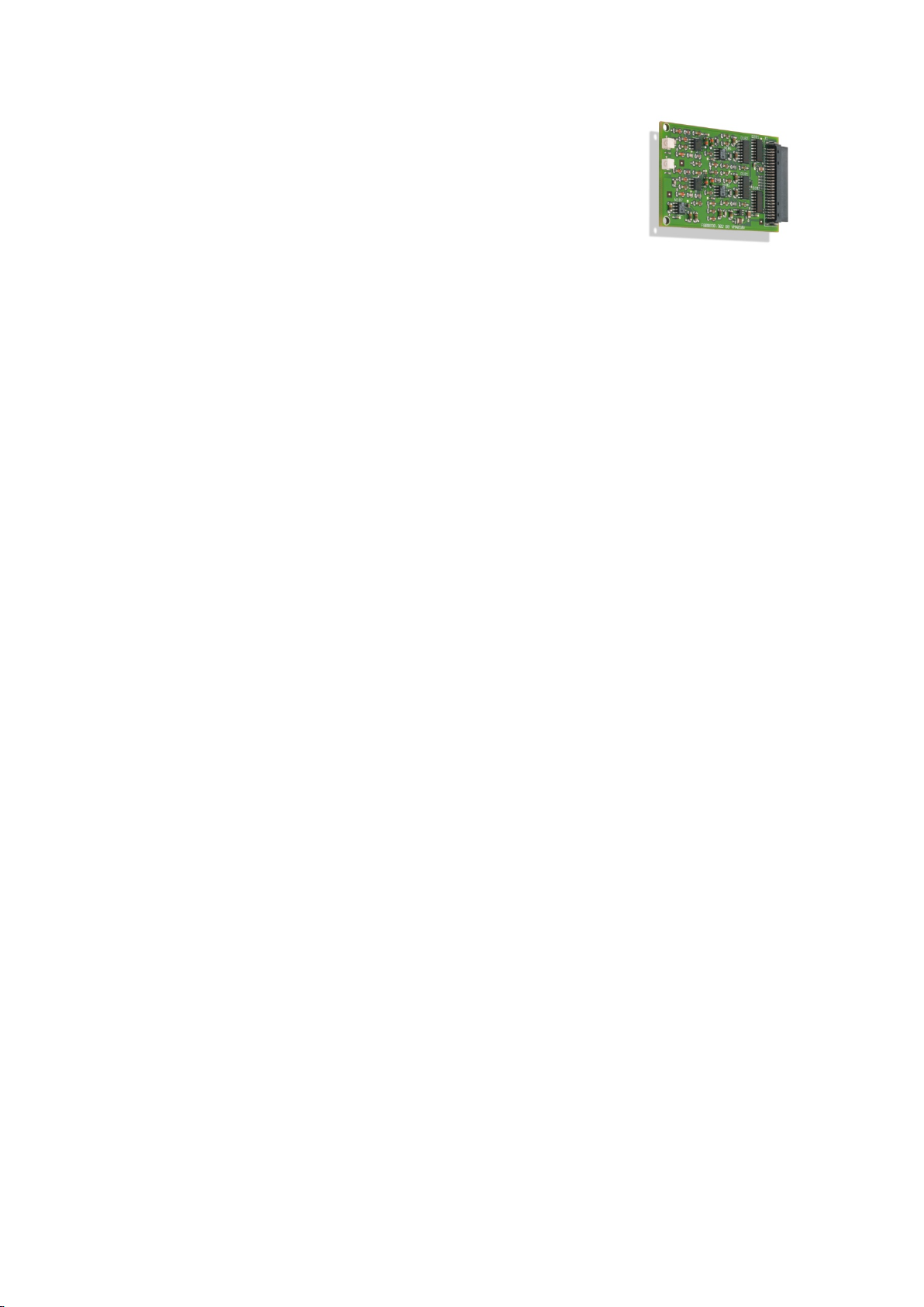
VC-6000TM Compact monitor Part B 2-channel conditioning module for BCU
6 2-channel conditioning module for
BCU
6.1 Function
♦ The conditioning module for BCU, abbreviated to BCU-CON (BCU-
Conditioning Module), is laid out for two measuring channels. Two
sensor signals can be evaluated independent of one another.
♦ The signal provided at each channel corresponds to the instantaneous
value of the measurement type BCU.
♦ A BCU-CON is internally managed through a Sensor block (Firmware).
Nevertheless the raw signals are continuously accessed from the
adjacent sensor modules. The connection and power to the sensors
must also be provided by the adjacent sensor modules.
♦ A BCU-CON combines the following hardware functions:
• Signal access at the adjacent sensor modules
• Signal amplifier
• Bandpass filtering (15 – 60 kHz)
• Signal evaluation by peak value detector
• Output of the instantaneous value of BCU
• LED signalling
6.2 Technical data
6.2.1 Electrical properties
Inputs: 2, from adjacent sensor modules
Signal filtering 15 ... 60 kHz
Signal detection Peak value detector
Signal output Instantaneous value of BCU
Accuracy error < 4,5 % of instantaneous value plus 0,2 %
of measurement range full scale value
- 32 - C100584.002 Module Vers. 08 © VC-6000
TM
Compact monitor Nov. 2014
Page 89
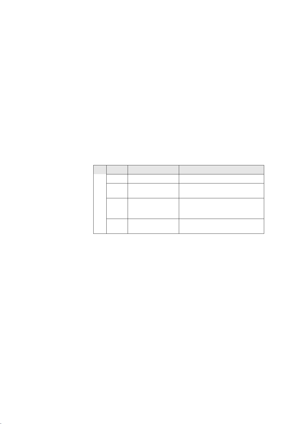
2-channel conditioning module for BCU Part B VC-6000TM Compact monitor
6.2.2 Equipment and signalling
♦ Possible socket positions on the Base Module X2_M
When the BCU-CON is located at position X2_M, it can be operated as
a 2-channel module. The signals from socket positions X1_M and
X3_M can be acquired and processed.
♦ The BCU-CON occupies a socket of a sensor module. Theoretically
more than one BCU-CON per Base module is possible, but the input
signals would be missing. As a result one BCU-CON per Base module
is the sensible limit.
♦ LED OVERLOAD (RD)
Each BCU-CON has 2 red LEDs.
The red LED provides information about the condition of the A/D
converter channel for the respective signal path. This displays whether
an over-range exists, or has existed, due to a high input signal or to a
selected input range that is too small or also whether everything is in
orders.
LED Status Explanation
Red Off No over-range
Red Flashing at 2 Hz A/D converter fault; not yet
confirmed through the dialogue
Red Flashing at 0,5 Hz No A/D converter fault currently
existing; an earlier fault not yet
confirmed through the dialogue
Red On A/D converter fault confirmed
AC-PATH
through the dialogue; still existing.
© VC-6000
TM
Compact monitor Nov, 2014 C100584.002 Module Vers. 08 - 33 -
Page 90
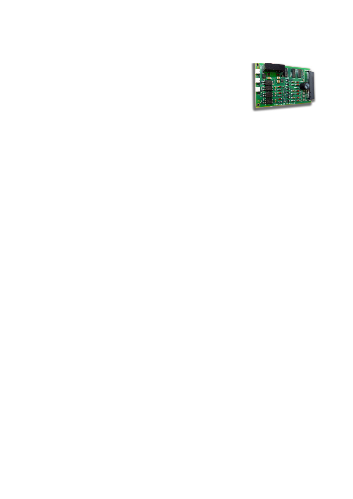
VC-6000TM Compact monitor Part B 3-channel input module for binary status signals
7 3-channel input module for binary
status signals
7.1 Function
♦ The input module for binary status signals,
abbreviated to BINARY-IN, is laid out for a
maximum of 3 input signals.
♦ Each BINARY-IN module is laid out to process either
1. non-active signals from external potential-free contacts,
2. active signals from external current sources (e.g. PNP opencollector) or
3. active signals from external current sinks (e.g. NPN open-collector).
With non-active signals the required auxiliary power is prepared by
the BINARY-IN module.
Active and non-active signals may not be simultaneously fed to the
same module because the switching of the auxiliary voltage is not done
separately to the channels.
♦ Each input channel of the BINARY-IN module is managed internally in
the instrument through a binary block (firmware), i.e. a BINARY-IN input
channel and a binary block together form a physical interface to the
outside world for the VIBROCONTROL 6000 Compact monitor. The
connected input signal is acquired and made available to the successive
signal path for further processing and assessment, e.g. switching the
Trip Multiply function on and off.
♦ The current logical state (ON or OFF) of each input channel is
displayed respectively by a yellow LED.
7.2 Technical data
7.2.1 Electrical properties
Input:
General properties galvanically-separate, polarized
Input impedance 3 kΩ
Maximum contact voltage 50 V
Minimum current load for potential-free contacts 5 mA
Accuracy 5 ms
Signal status LOW:
Nominal input voltage 0 V DC
Input voltage range -50 V...+ 5,0 V DC
Maximum input current 1 mA
Signal status HIGH:
Nominal input voltage + 24 V DC
Input voltage range + 16,5 V...+ 50 V DC
Minimum input current 5 mA
- 34 - C100584.002 Module Vers. 08 © VC-6000TM Compact monitor Nov. 2014
Page 91
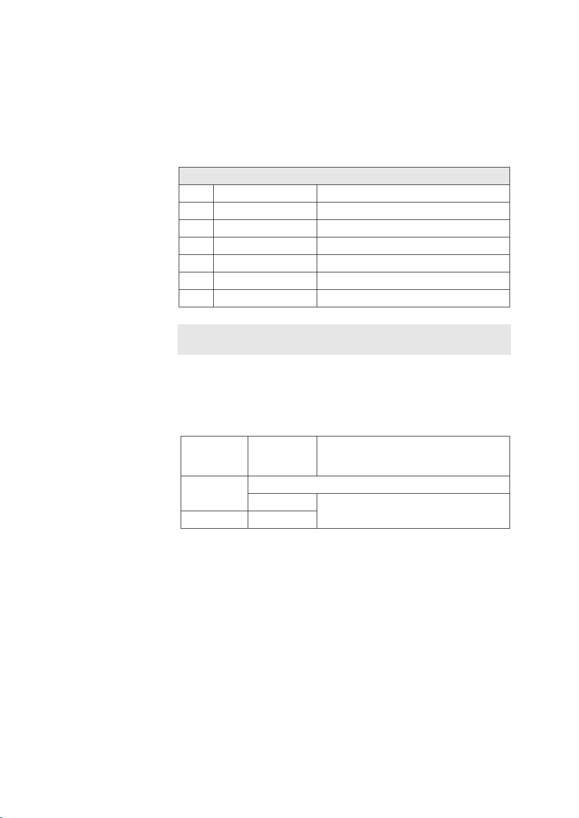
3-channel input module for binary status signals Part B VC-6000TM Compact monitor
7.2.2 Equipment and signalling
♦ Possible socket positions on the Base module X1_M to X9_M
♦ Connection plugs on the Base module X1 to X9
♦ Connection plug layout with BINARY-IN equipment
BINARY-IN Connection pin layout X4 to X9
PIN Signal Explanation
1 HI A Channel A input HIGH
2 LO A Channel A input LOW
3 HI B Channel B input HIGH
4 LO B Chanel B input LOW
5 HI C Channel C input HIGH
6 LO C Channel C input LOW
Note:
The inputs A,B,C are not separated galvanically
♦ Status LED (yellow)
The yellow LEDs signal the current logical evaluated state of the
respective assigned channel.
Status
LED
(yellow)
Off Undefined channels are not evaluated
On ON
Logical
state
OFF Dependent upon the parameter „Active
Input signal
State“, see Binary block for details
© VC-6000
TM
Compact monitor Nov, 2014 C100584.002 Module Vers. 08 - 35 -
Page 92
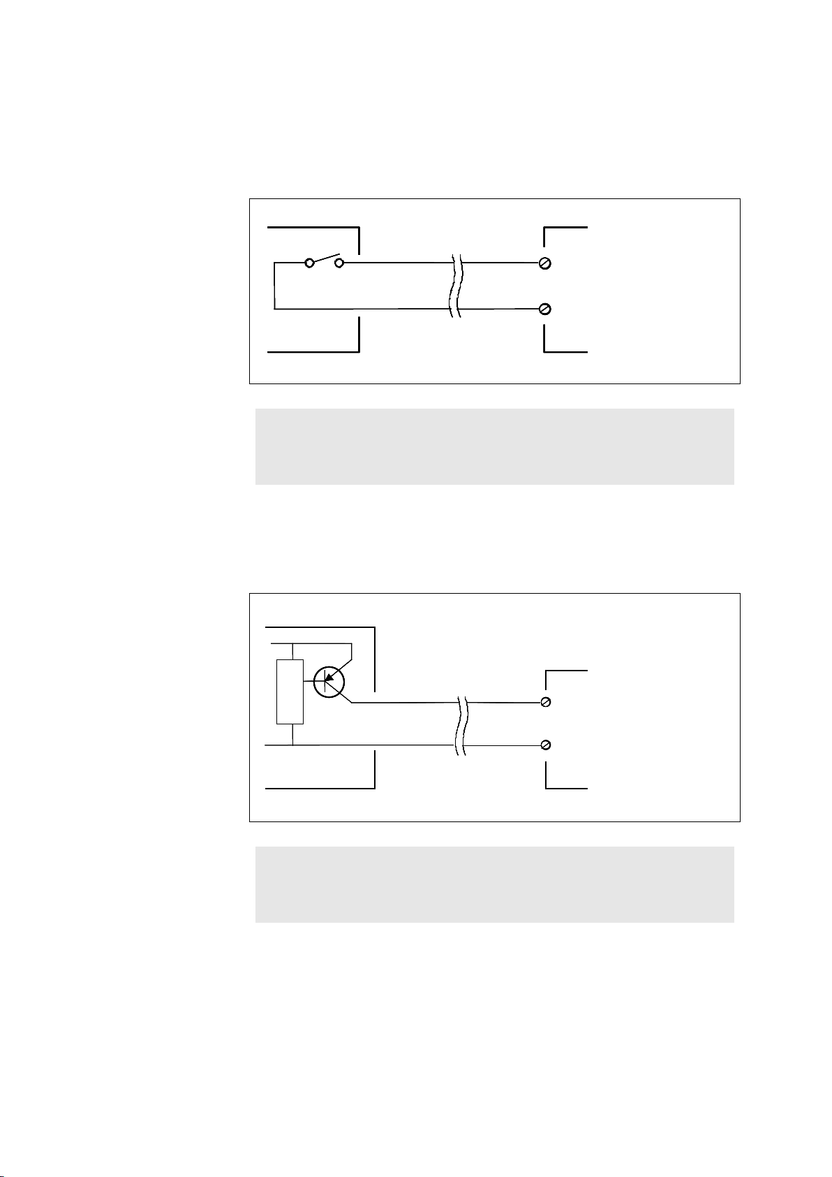
VC-6000TM Compact monitor Part B 3-channel input module for binary status signals
Binary input
HI
LO
Machine control
VIBROCONTROL 6000
Compact monitor
Binäreingang (050805)
Binary input
HI
LO
Machine control
VIBROCONTROL 6000
Compact monitor
Binäreingang (050805)
HI
LO
+ 24 V
0 V
Binary input
HI
LO
Machine control
+ 24 V
0 V
VIBROCONTROL 6000
Compact monitor
Binäreingang PNP (050805)
HI
LO
+ 24 V
0 V
Binary input
HI
LO
Machine control
+ 24 V
0 V
VIBROCONTROL 6000
Compact monitor
Binäreingang PNP (050805)
7.3 Wiring of binary inputs
7.3.1 External potential-free contacts (non-active signals)
Note:
The setup parameter <Active Signal> MUST be given the setting „NO“.
Thereby the auxiliary voltage source for the BINARY-IN module is switched
on and supplies the necessary auxiliary power for the control circuit.
7.3.2 Active signals from external current sources (PNP opencollector)
Note:
- 36 - C100584.002 Module Vers. 08 © VC-6000
The setup parameter <Active Signal> MUST be given the setting „YES“.
Thereby the auxiliary voltage to the BINARY-IN module is switched off as
active signals do not require auxiliary power.
TM
Compact monitor Nov. 2014
Page 93
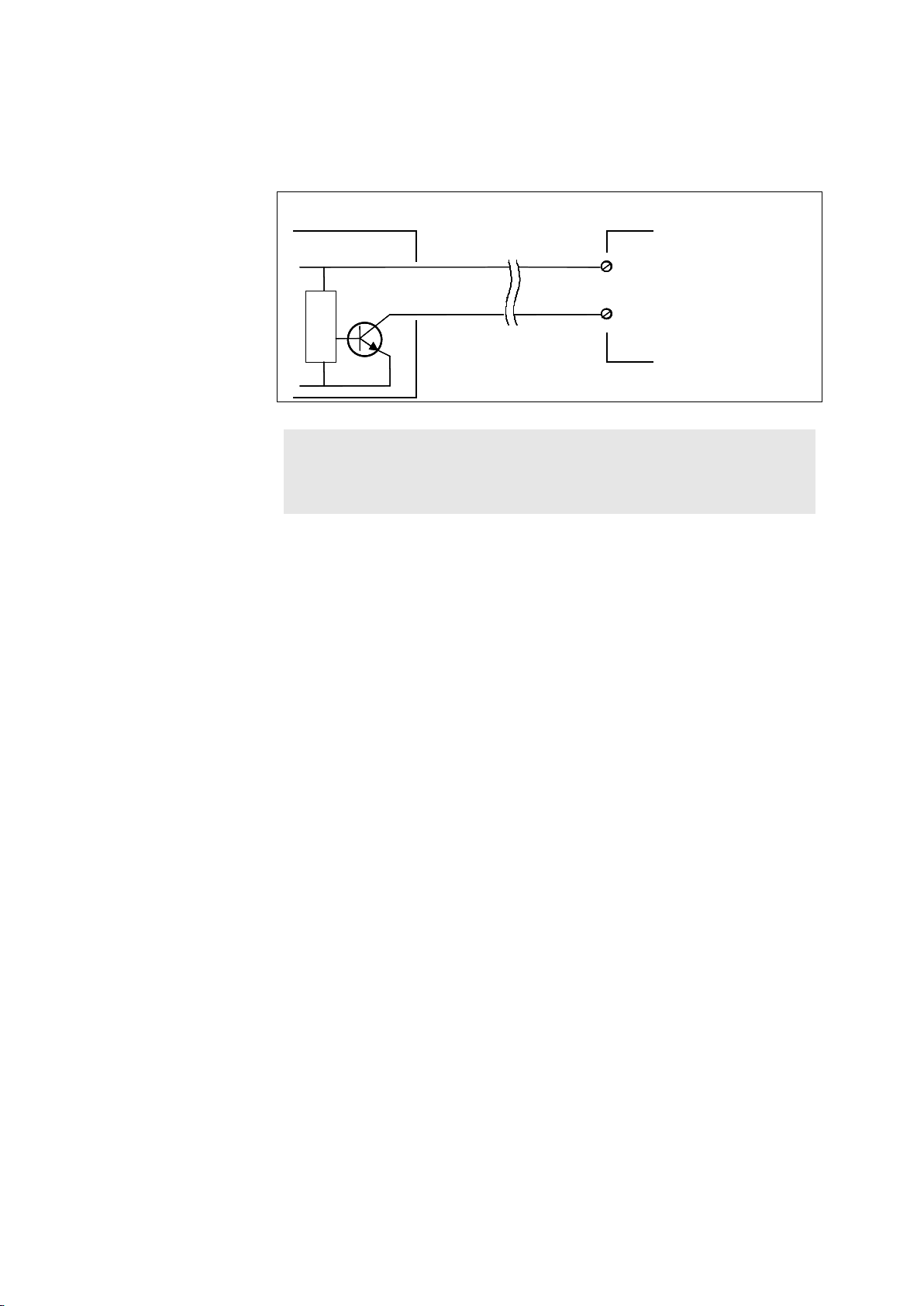
3-channel input module for binary status signals Part B VC-6000TM Compact monitor
HI
LO
Machine control
+ 24 V
0 V
Binary input
HI
LO
+ 24 V
0 V
VIBROCONTROL 6000
Compact monitor
Binäreingang NPN (050805)
HI
LO
Machine control
+ 24 V
0 V
Binary input
HI
LO
+ 24 V
0 V
VIBROCONTROL 6000
Compact monitor
Binäreingang NPN (050805)
7.3.3 Active signals from external current sinks (NPN open-collector)
Note:
The setup parameter <Active Signal> MUST be given the setting „YES”.
Thereby the auxiliary voltage source to the BINARY-IN module is switched
off as active signals do not require auxiliary power.
© VC-6000
TM
Compact monitor Nov, 2014 C100584.002 Module Vers. 08 - 37 -
Page 94
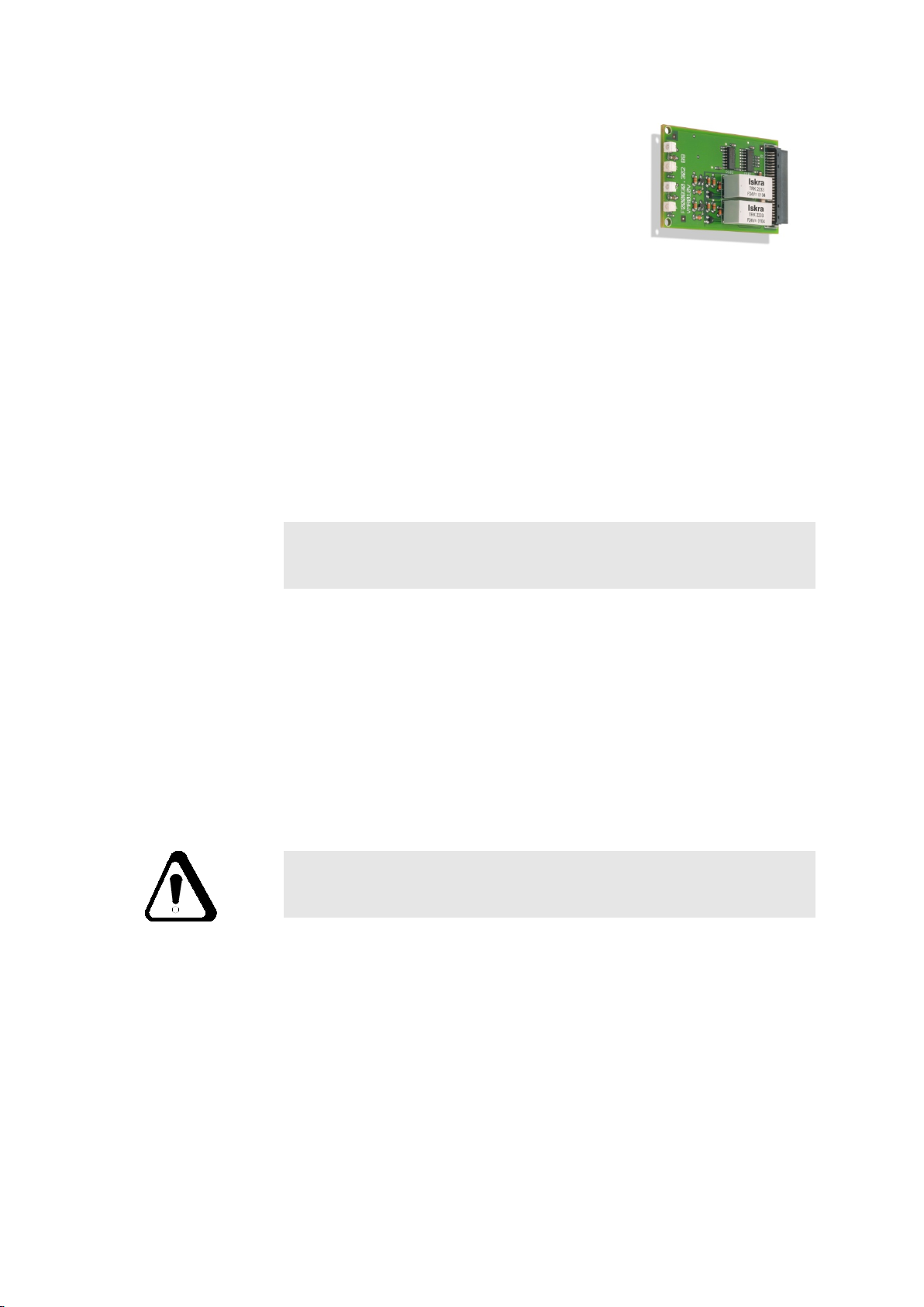
VC-6000TM Compact monitor Part B 2-channel Relay output module
8 2-channel Relay output module
8.1 Function
♦ The relay output module is laid out for two
output channels. Each output channel uses a
change-over relay for switching of potential-free contacts.
♦ Each relay output module has 4 LEDs, of which 2 are respectively
assigned to one relay. Each relay thus has two LEDs, one green and
one two-colour red/yellow LED. All LEDs are used for local signalling of
of the operating and switching status of the relays.
♦ As a rule the Relay module is controlled internal to the system (see
Signal-flow chart) by preceding Monitoring blocks (Monitor) or Logic
blocks)
♦ The LEDs of the relay output modules signal the status of the limits
monitored by the Monitor block. The type and manner of signalling is
determined by global and internal block parameters.
Note:
The signalling of the LEDs is described in section „Introduction“,
chapter 8.3.3.
8.2 Technical data
8.2.1 Electrical data
Relay type change-over, mono-stable
Nominal operating voltage 24...48 V
Maximum contact voltage < 50 V
Maximum current load < 500 mA
Minimum current 10 µA
Minimum voltage 10 mV
Caution!
The maximum values must not be exceeded. Take precautions for inductive
or capacitive loads.
- 38 - C100584.002 Module Vers. 08 © VC-6000
TM
Compact monitor Nov. 2014
Page 95
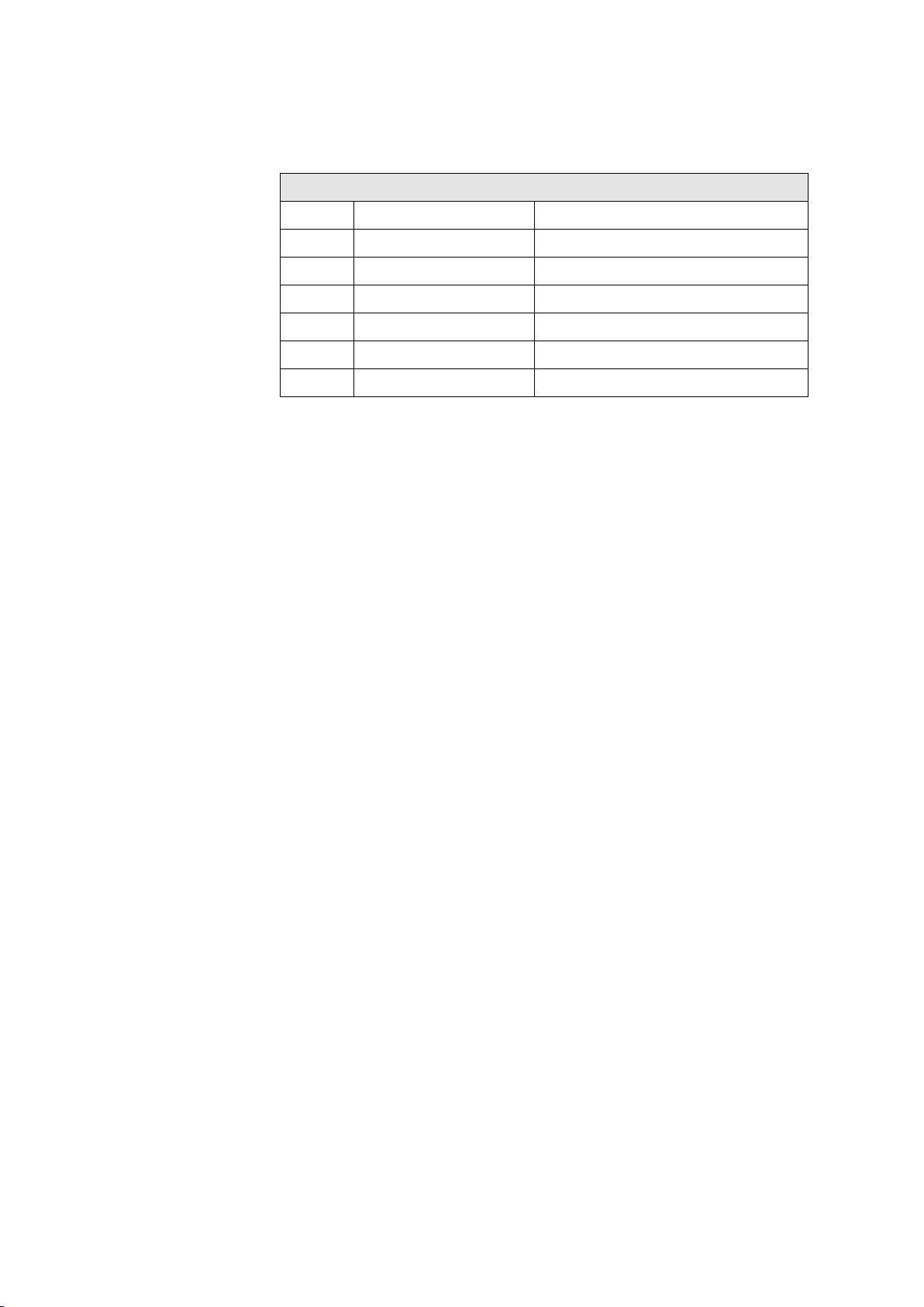
2-channel Relay output module Part B VC-6000TM Compact monitor
8.2.2 Connection plug layout
Relay output module pin layout connections X1/X2/X3
PIN Signal Explanation
1
2
3
4
5
6
ARM RelA
NO RelA
NC RelA
ARM RelB
NO RelB
NC RelB
Arm, relay A
Normally-open contact, relay A
Normally-closed contact, relay A
Arm, relay B
Normally-open contact, relay B
Normally-closed contact, relay B
© VC-6000
TM
Compact monitor Nov, 2014 C100584.002 Module Vers. 08 - 39 -
Page 96
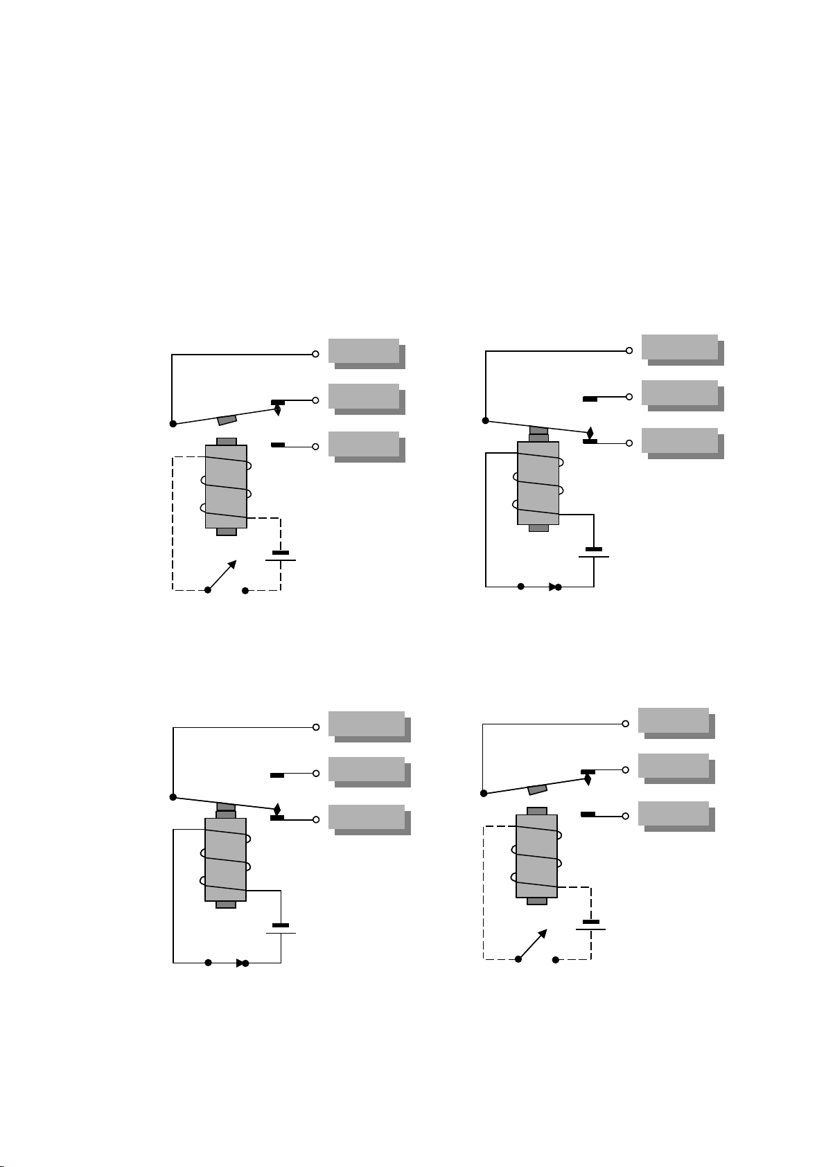
VC-6000TM Compact monitor Part B 2-channel Relay output module
Pin 1 (4)
Pin 1 (4)
Pin 3 (6)
Pin 3 (6)
Pin 2 (5)
Pin 2 (5)
Pin 1 (4)
Pin 1 (4)
Pin 3 (6)
Pin 3 (6)
Pin 2 (5)
Pin 2 (5)
Pin 1 (4)
Pin 1 (4)
Pin 3 (6)
Pin 3 (6)
Pin 2 (5)
Pin 2 (5)
Pin 1 (4)
Pin 1 (4)
Pin 3 (6)
Pin 3 (6)
Pin 2 (5)
Pin 2 (5)
Pin 1 (4)
Pin 1 (4)
Pin 3 (6)
Pin 3 (6)
Pin 2 (5)
Pin 2 (5)
Pin 1 (4)
Pin 1 (4)
Pin 3 (6)
Pin 3 (6)
Pin 2 (5)
Pin 2 (5)
8.3 Wiring of relay outputs
8.3.1 Relay switch mode
When connnecting the relay contact it should be noted that the relay outputs
can be operated selectively as normally de-energised or normally energised
relays (see figure for details)
Pins no. 1-3 are referred to channel A, and pins no. 4-6 to channel B.
Principle diagram for normally de-energised switching:
Normal position Position after an event signal
Principle diagram for normally energised switching:
Normal position Position after an event signal
- 40 - C100584.002 Module Vers. 08 © VC-6000
TM
Compact monitor Nov. 2014
Page 97
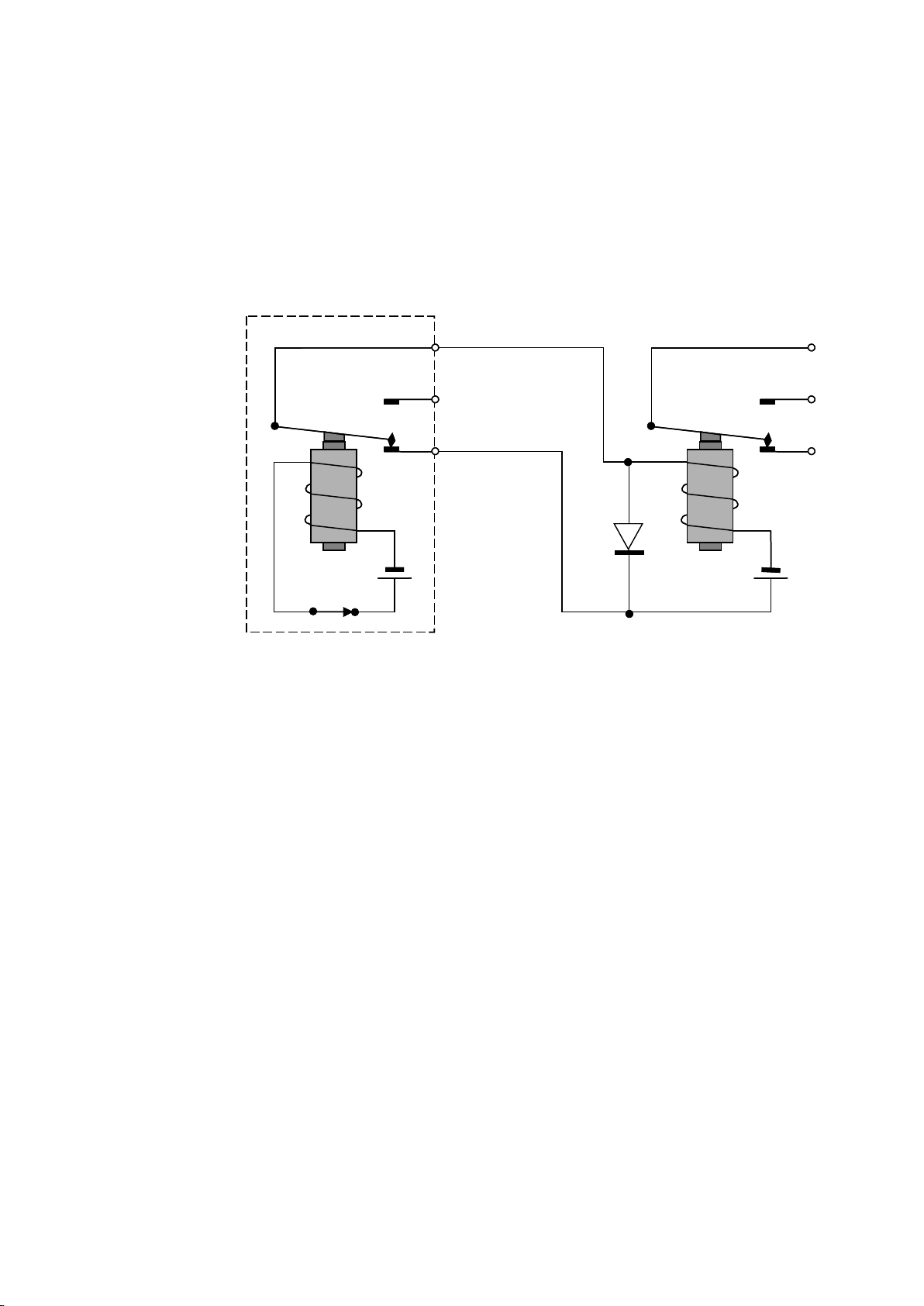
2-channel Relay output module Part B VC-6000TM Compact monitor
8.3.2 Controlling an external power relay
The relay output module is laid out for switching low power. If higher power
switching is required this can be realised through supplementary externally
mounted power relays.
VIBROCONTROL 6000
VIBROCONTROL 6000
Relay
Relay
Figure. Example for controlling an external power relay
Compact monitor
Compact monitor
External power relay
External power relay
+
+
© VC-6000
TM
Compact monitor Nov, 2014 C100584.002 Module Vers. 08 - 41 -
Page 98
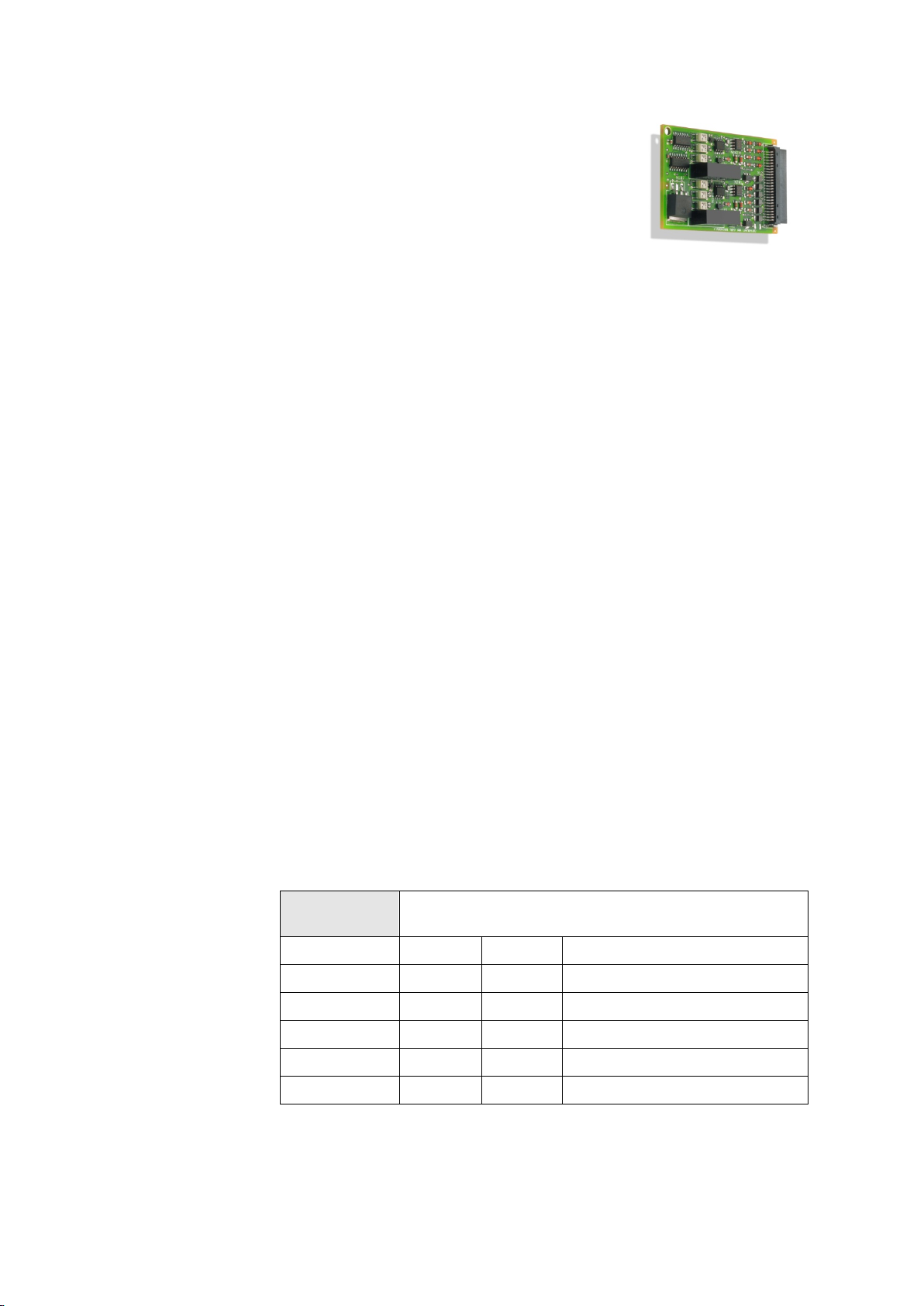
VC-6000TM Compact monitor Part B 2-channel output module for current / voltage
9 2-channel output module for
current / voltage
9.1 Function
♦ The output module for current and voltage
signals, abbreviated to DC-OUT (DC-OUTPUT-Module) is laid out as a
2-output channel.
♦ The DC-OUT module is an interface between the
VIBROCONTROL 6000 Compact monitor and the outside world. The
output can be selected as a potential-free DC-current signal (e.g. 4 ... 20
mA) or a potential-free DC voltage signal (e.g. 0 ... 10 V). Both signal
types are presented at each DC-OUT Module. Selection is done
respectively through a corres-ponding connection layout.
♦ A DC output is always directly linked with a measurement processor
(e.g. an RMS block). The output signal level of the DC output represents, as a rule, the current measured value. The representation of the
measured value by an output signal level is set up through the dialogue
of the User-Terminal and can be changed at any time by the user.
9.2 Technical data
9.2.1 Output
General properties galvanically separate,
short-circuit proof
Output range for current signal 0 ... 20 mA and 4 ... 20 mA
Max. load for current signal 500 Ω
Output range for voltage signal 0 ... 10 V and 2 ... 10 V
Min. load for voltage signal 10 kΩ
Dynamics 1
9.2.2 Connection plug layout
Plug
X4 to X9
Pin 1 Volt A OUT Voltage output, channel A
Pin 2 Curr A OUT Current out, channel A
Pin 3 COM A OUT Common, channel A
DC-OUT (up to 2 channels: A and B)
Pin 4 Volt B OUT Voltage output, channel B
Pin 5 Curr B OUT Current output, channel B
Pin 6 COM B OUT Common, channel B
- 42 - C100584.002 Module Vers. 08 © VC-6000
TM
Compact monitor Nov. 2014
Page 99

C
Komponenten des Signalflussgraphs
Components of the signal flow chart
Composantes de signeaux flux
VC-6000 Compact monitor
Page 100

All rights reserved.
No part of this publication may be reproduced, stored in a retrieval system or
transmitted, in any form, or by any means, electronic, mechanical,
photocopying, recording or otherwise without prior written permission from
Brüel & Kjær Vibro GmbH.
The right to make changes at any time without notice is reserved.
Copyright 2011 by Brüel & Kjær Vibro GmbH, D-64293 Darmstadt
Tel.: +49 (0)6151 428 –1400 Fax: +49 (0)6151 428 –1401
Internet:
 Loading...