

Page 1

Model: XLN3640, XLN6024, XLN8018, XLN10014
High Power Programmable
DC Power Supply
Click for models XLN15010, XLN30052 & XLN60026
USER MANUAL
www. .com
information@itm.com1.800.561.8187
Page 2

Safety Summary
The following safety precautions apply to both operating and maintenance personnel
and must be observed during all phases of operation, service, and repair of this
instrument. Before applying power, follow the installation instructions and become
familiar with the operating instructions for this instrument.
Failure to comply with these precautions or with specific warnings elsewhere in this
manual violates safety standards of design, manufacture, and intended use of the
instrument. B &K Precision assumes no liability for a customer’s failure to comply
with these requirements. This is a Safety Class I instrument.
GROUND THE INSTRUMENT
To minimize shock hazard, the instrument chassis and cabinet must be
connected to an electrical ground. This instrument is grounded through the
ground conductor of the supplied, three-conductor ac power cable. The
power cable must be plugged into an approved three-conductor electrical
outlet. Do not alter the ground connection. Without the protective ground
connection, all accessible conductive parts (including control knobs) can
render an electric shock. The power jack and mating plug of the power cable
meet IEC safety standards.
DO NOT OPERATE IN AN EXPLOSIVE ATMOSPHERE
Do not operate the instrument in the presence of flammable gases or fumes.
Operation of any electrical instrument in such an environment constitutes a
definite safety hazard.
KEEP AWAY FROM LIVE CIRCUITS
Instrument covers must not be removed by operating personnel. Component
replacement and internal adjustments must be made by qualified maintenance
personnel. Disconnect the power cord before removing the instrument
covers and replacing components. Under certain conditions, even with the
power cable removed, dangerous voltages may exist. To avoid injuries,
always disconnect power and discharge circuits before touching them.
DO NOT SERVICE OR ADJUST ALONE
Do not attempt any internal service or adjustment unless another person,
capable of rendering first aid and resuscitation, is present.
www. .com
information@itm.com1.800.561.8187
Page 3

DO NOT SUBSTITUTE PARTS OR MODIFY THE INSTRUMENT
Do not install substitute parts or perform any unauthorized modifications to
this instrument. Return the instrument to B&K Precision for service and
repair to ensure that safety features are maintained.
WARNINGS AND CAUTIONS
WARNING and CAUTION statements, such as the following examples,
denote a hazard and appear throughout this manual. Follow all instructions
contained in these statements.
A WARNING statement calls attention to an operating procedure, practice, or
condition, which, if not followed correctly, could result in injury or death to
personnel.
A CAUTION statement calls attention to an operating procedure, practice, or
condition, which, if not followed correctly, could result in damage to or
destruction of part or all of the product.
WARNING:
Do not alter the ground connection. Without the protec
tive ground
connection, all accessible conductive parts (including control knobs)
can render an electric shock. The power jack and mating plug of the
power cable meet IEC safety standards.
WARNING:
To avoid electrical shock hazard, disconnect power cord
before
removing covers. Refer servicing to qualified personnel.
CAUTION:
Before connecting the line cord to the AC mains, check the rear panel
AC line voltage indicator. Applying a line voltage other than the
indicated voltage can destroy the AC line
fuses. For continued fire
protection, replace fuses only with those of the specified voltage and
current ratings.
CAUTION:
This product uses components which can be damaged by
electro-
static discharge (ESD). To avoid damage, be sure to follow
proper pr
ocedures for handling, storing and transporting parts and
subassemblies which contain ESD-sensitive components.
www. .com
information@itm.com1.800.561.8187
Page 4

1
Store/Move/Maintain
Storage
When this device i s n ot i n u se, p roperly p ackage i t and store i t in an
environment suitable for storage (if present in a good preserving environment,
the packaging process can be waived).
Freight
While m oving t his pr oduct, m ove i t by us ing t he o riginal packaging to pa ck
this pr oduct i n a dvance. I f t he packaging material i s l ost, u se an eq uivalent
buffer material to replace i t i n p ackaging; an d with external m arks i ndicating
“fragile & water-prevention”.
Maintenance
Please r eturn the pow er s upply to fa ctory fo r any repair, s ervice, o r
maintenance.
Disposal
When the device is in an u nusable condition a nd can’t b e r epaired, p lease
discard it a ccording t o y our c ompany’s disposal p rocedures or local l egal
procedures. Don’t discard arbitrarily to avoid polluting the environment.
www. .com
information@itm.com1.800.561.8187
Page 5

2
Table of Contents
1. Preface ...................................................................................................... 1
1.1 Products Outline ................................................................................ 1
1.2 Features ............................................................................................. 2
1.3 Specifications .................................................................................... 4
2. Cautions Before Using ............................................................................ 9
2.1 Check and Confirm Accessories before Using .................................. 9
2.2 Operation Instructions ....................................................................... 9
2.3 Ambient Environment ....................................................................... 9
2.4 Storage ............................................................................................. 10
2.5 Power-line voltage ........................................................................... 10
2.6 Fuses ................................................................................................ 10
2.7 Warm-up Time ................................................................................. 11
2.8 Power-off procedure ........................................................................ 11
2.9 Cautions in Operation ...................................................................... 11
3. Front Panel Operation .......................................................................... 12
3.1 XLN3640/XLN6024/XLN8018/XLN10014 Panel ......................... 12
3.1.1 Front Panel ................................................................................. 12
3.1.2 Rear Panel .................................................................................. 30
4. Operation Instructions ......................................................................... 34
4.1 Voltage Setting................................................................................. 34
4.2 Current Setting ................................................................................ 34
4.3 Over-voltage Protection OVP .......................................................... 34
4.4 Over-current Protection OCP .......................................................... 34
4.5 Voltage Output ................................................................................. 35
www. .com
information@itm.com1.800.561.8187
Page 6

3
4.6 Control Voltage Output with Rotary knob ....................................... 35
4.7 Timer Function ................................................................................ 35
4.8 Series (cascade) / Parallel Mode Setting ......................................... 36
4.8.1 Parallel Connection Setting ........................................................ 36
4.8.2 Series Mode Setting ................................................................... 38
4.8.3 Error Message of Series/Parallel Connection ............................ 41
4.9 External Tuning Setting ................................................................... 42
4.10 Timer of Current Flow ..................................................................... 43
4.11 Programmable Capability (SCPI Command Only) ......................... 44
4.12 Multi-unit Connection mode (RS485) ............................................. 50
5. Protection and Error Messages............................................................ 54
5.1 Over-voltage Protection (OVP) ....................................................... 54
5.2 Over-current Protection (OCP) ........................................................ 54
5.3 Overpower Protection (OPP) ........................................................... 54
5.4 Constant Voltage Protection (CV TO CC) ....................................... 55
5.5 Constant Current Protection (CC TO CV)....................................... 55
5.6 Over-temperature Protection (OTP) ................................................ 55
5.7 Low Voltage Protection (ACD) ....................................................... 56
5.8 Error Input Message ........................................................................ 56
6. Remote Interface communication protocol ........................................ 57
6.1 Prefaces ........................................................................................... 57
6.2 Parameters Definition ...................................................................... 57
6.3 The Error/Event List ........................................................................ 58
6.4 Remote Communication Protocol ................................................... 59
6.5 SCPI Conformity Information ......................................................... 62
6.5.1 Common SCPI commands ......................................................... 62
6.5.2 SCPI Command subsystem ........................................................ 63
www. .com
information@itm.com1.800.561.8187
Page 7

4
6.6 State Bit Definition .......................................................................... 74
6.7 LAN Communication (-GL versions) .............................................. 75
Using Web Server........................................................................................... 75
Main Page (Home) .................................................................................. 75
Using Telnet ............................................................................................ 78
Using Sockets .......................................................................................... 78
7. Assemble Accessories ............................................................................ 79
7.1 Assemble Rack Mount Brackets ..................................................... 79
7.2 Assembly of Output Protective Cover
(XLN6024/XLN8018/XLN10014) .................................................. 80
7.3 Assembly of Remote Sense Protective Cover
(XLN6024/XLN8018/XLN10014) .................................................. 81
8. Accessories ............................................................................................. 82
9. Service Information .............................................................................. 84
10. Limited Three-year Warranty ............................................................. 85
www. .com
information@itm.com1.800.561.8187
Page 8

1
1. Preface
1.1 Products Outline
B&K P recision models XLN3640/XLN6024/XLN8018/XLN10014 are
programmable D C pow er supplies with s ingle ou tputs that of fer t he
maximum power output up to 1440 watts (0 -- 36 V/40 A or 0 -- 60 V/24 A
or 0 -- 80 V/18 A or 0 -- 100 V/14.4 A). With a 16-bit D/A, A/D converter
embedded, the pow er supplies come w ith the resolution of 1mV i n voltage
setting and 1mA in current setting. By connecting up to 4 power supplies in
parallel o r se ries, a maximum power out put up t o 5760 watts can be
generated. With four XLN10014 connected in s eries, the maximum output
voltage can reach 400 V. W ith four XLN3640 connected in parallel, t he
output current can reach up to 160 A.
The XLN series provides a rotary control knob and numerical and function
keys to m ake t he instrument c onvenient a nd e asy t o use. Additionally, th e
power supplies provide a memory space for storage of 10 instrument settings
that can be recalled directly. This feature offers a n easy w ay t o r estore t he
application settings. In addition, users can program to control when to cut off
the output. This feature provides extra safety f or burn-in a nd e lectroplating
applications. The supplies also pr ovide over voltage protection (OVP), over
current protection (OCP), and over power protection (OPP) features used to
keep t he out put v oltage a nd c urrent w ithin s afety le vel and preventing
damage to the UUT (Unit Under Test) due to excessive current. The key lock
feature is added to avoid accidental setting changes to the XLN series. When
the i nput pow er a nd the l oad c hange, t he power supplies maintain a stable
output due to load and line regulation of less than 0.05%; the transient time
less than 1 m s. In remote mode, the s upplies can output a n ew
voltage/current setting 50 ms after receiving a command, which can increase
the throughput on production lines.
www. .com
information@itm.com1.800.561.8187
Page 9

2
1.2 Features
1) Output Voltage & Current
Voltage output range: 0 -- 36V (XLN3640) / 0 -- 60V (XLN6024)
0 -- 80V (XLN8018) / 0 -- 100V
(XLN10014)
Current output range: 0 -- 40A (XLN3640) / 0 -- 24A (XLN6024)
0 -- 18A (XLN8018) / 0 -- 14.4A
(XLN10014)
Power output range: 0 -- 1440W
2) Rotary knob, numerical keys and functions keys
The rotary knob can be used t o rapidly ch ange the o utput voltage s etting
and si mulate t he surge of the voltage output. It offers a good s olution for
testing triggering c ircuits. Numerical k eys allow f or direct e ntry o f
parameters. U sing function k eys t o s witch modes m akes t he overall
operation more convenient.
3) Precise voltage and current measurement
Besides t he pr ecise out put, the X LN s eries also of fers the cap ability to
measure voltage & cu rrent accurately (read b ack), saving users the extra
expense and space for extra measuring instruments.
4) Internal memory and timer function
The XLN series provides a memory s pace for storage an d r etrieval of 10
instrument settings. The instruments provide one (1) ti mer w ith the
resolution o f 1 s econd. The t imers a re used to time the outputs. When the
timer c ounts down t o z ero t he power s upply will a utomatically turn th e
output off. This feature is useful when the supply is providing power to the
test o bject in a burn-in r oom where o perators can precisely set t he t ime
when the equipment is to shut off.
5) OVP (over voltage protection), OCP (over current protection) and OPP
(over power protection) and key lock functions
The over voltage protection (OVP), over current protection (OCP) and over
power protection (OPP) features limit t he m aximum output c urrent and
voltage t o av oid d amages t o the unit unde r test (UUT). The ke y l ock
feature d isables a ll k eys e xcept the C LR k ey. It p revents damaging the
www. .com
information@itm.com1.800.561.8187
Page 10

3
UUT by accidentally entering the wrong settings.
6) Series & parallel connection mode
The series-parallel connection mode of two or more units (maximum to 4
units) significantly increases the combined output power to a maximum of
5760 W. In parallel connection mode of four XLN3640 the maximum
output is 36 V/160 A; and in series connection mode of four XLN10014,
the maximum output is 400 V/14.4 A.
7) Multi-unit connection mode
The RS 485 interface can be used to connect multiple power supplies in
series, up to maximum of 30 units. They can be controlled via USB
interface with a computer.
www. .com
information@itm.com1.800.561.8187
Page 11
4
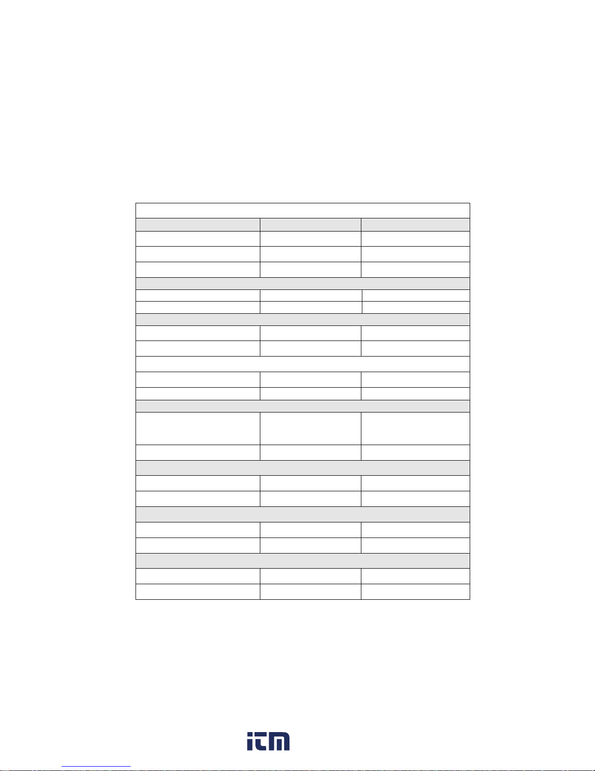
1.3 Specifications
XLN3640/XLN6024 Specifications
Output Rating
XLN3640 XLN6024
Output Voltage 0--36 V 0--60 V
Output Current 0--40 A 0--24 A
Output Power 1440 W 1440 W
Output Protection
OVP Adjustment Range
2--38 V
3--64 V
OVP Accuracy
200 mV
300 mV
Line Regulation
Voltage ≤ 4 mV ≤ 6 mV
Current ≤ 4 mA ≤ 4 mA
Load Regulation
Voltage ≤ 8 mV ≤ 8 mV
Current
≤ 8 mA
≤ 7 mA
Ripple/Noise (20Hz-20MHz)
Normal Mode Voltage
( ≥ 0.5 % of max. power)
≤ 5 mVrms/≤ 60 mVpp ≤ 6 mVrms/≤ 70 mVpp
Normal Mode Current ≤ 90 mA ≤ 70 mA
Programming Resolution
Programming 1 mV/1 mA 1.5 mV/1 mA
Readback 1 mV/1 mA 1.5 mV/1 mA
Programming Accuracy ±(% output+offset)
Voltage 0.05 %+10 mV 0.05 %+15 mV
Current 0.05 %+10 mA 0.05 %+18 mA
Readback Accuracy ±(% output+offset)
Voltage 0.05 %+10 mV 0.05 %+15 mV
Current 0.05 %+10 mA 0.05 %+18 mA
www. .com
information@itm.com1.800.561.8187
Page 12

5
General
Average Command Response
Time
<50 ms <50 ms
Power Factor Correction
0.99
(Full load)
0.99
(Full load)
Remote Sense Compensation 2V 2V
Rising Time at Full Load ≤ 15 ms ≤ 20 ms
Rising Time at No Load ≤ 15 ms ≤ 20 ms
Falling Time at Full Load ≤ 15 ms ≤ 20 ms
Falling Time at No Load ≤ 1000 ms ≤ 1000 ms
Standard Interface USB
Transient Response Time ≤ 1 ms
Efficiency 80 %
AC Line Rated Input Voltage
100--240 VAC
(Full load)
Tolerance/Variation in
Voltage
-15% -- +10%
(10% power de-rating mode
when voltage under 95 VAC)
Rated Frequency 47 Hz--63 Hz
Maximum Rated Input Power 1700 VA
Temperature Ratings(O) Operation (0 °C -- 40 °C)
Temperature Ratings(S) Storage (-10 °C -- 70 °C)
Dimensions(W*H*D) 16.5 x 1.7 x 17 inch(420 x 43.6 x 432 mm)
Weight 19.8 lbs. (9 kg)
Standard Accessories
Power Cord, Terminal Blocks for Rapid Plug
Connector, Rackmount Kit, Manual
Standard Interface USB
Optional Interface LAN & GPIB
www. .com
information@itm.com1.800.561.8187
Page 13

6
XLN8018/XLN10014 Specifications
Output Rate
XLN8018 XLN10014
Output Voltage
0~80 V 0~100 V
Output Current
0~18 A 0~14.4 A
Output Power 1440 W 1440 W
Output Protection
OVP Adjustment Range
4~85 V 5~105 V
OVP Accuracy 400 mV 500 mV
Line Regulation
Voltage ≤ 8 mV ≤ 10 mV
Current ≤ 4 mA ≤ 4 mA
Load Regulation
Voltage ≤ 10 mV ≤ 12 mV
Current ≤ 6.5 mA ≤ 6 mA
Ripple/Noise (20Hz-20MHz)
Normal Mode Voltage
( ≥ 0.5 % of max. power)
≤ 7 mVrms/≤ 80
mVpp
≤ 8 mVrms/≤ 80 mVpp
Normal Mode Current ≤ 50 mA ≤ 40 mA
Programming Resolution
Programming 2 mV/1 mA 2.5 mV/1 mA
Readback 2 mV/1 mA 2.5 mV/1 mA
Programming Accuracy ±(% output+offset)
Voltage 0.05 %+20 mV 0.05 %+25 mV
Current 0.05 %+7 mA 0.05 %+6 mA
Readback Accuracy ±(% output+offset)
Voltage 0.05 %+20 mV 0.05 %+25 mV
Current 0.05 %+7 mA 0.05 %+6 mA
General
www. .com
information@itm.com1.800.561.8187
Page 14

7
Average Command
Response Time
<50 ms <50 ms
Power Factor Correction
≥ 0.99
(Full load)
≥ 0.99
(Full load)
Remote Sense
Compensation
2 V 2 V
Rising Time at Full Load ≤ 25 ms ≤ 30 ms
Rising Time at No Load ≤ 25 ms ≤ 30 ms
Falling Time at Full Load ≤ 25 ms ≤ 30 ms
Falling Time at No Load ≤ 1000 ms ≤ 1000 ms
Transient Response Time ≤ 1 ms
Efficiency ≥ 80 %
AC Line Rated Input
Vo l t a g e
100~240 VAC
( Full load )
Tolerance/Variation in
Voltage
-15 %~+10 %
( 10 % power de-rating mode
when voltage under 95 VAC )
Rated Frequency
47 Hz~63 Hz
Maximum Rated Input
Power
1700 VA
Temperature Ratings(O) Operation (0 °C -- 40 °C)
Temperature Ratings(S) Storage (-10 °C -- 70 °C)
Dimensions(W*H*D) 16.5 x 1.7 x 17 inch (420 x 43.6 x 432 mm)
Weight 19.8 lbs. (9 kg)
Standard Accessories
Power Cord, Terminal Blocks for Rapid Plug
Connector, Rackmount Kit, Manual
Standard Interface USB
Option Interface LAN & GPIB
Specifications and information is subject to change without notice
www. .com
information@itm.com1.800.561.8187
Page 15

8
Features of models XLN3640/XLN6024/XLN8018/XLN10014:
Graphical, easy to read LCD display
Compact, high efficiency and power density
40 A output connector for quick connectivity
Convenient numerical & function keys
Store and recall 10 instrument settings
Timer (1 sec -- 100 hours)
Programmable (SCPI command only)
List mode supports up to 10 s ets o f pr ogram and m aximum 150 s teps in
total
Auxiliary 5 V/1 A output
Built-in precise voltage and current measurement
OVP, OCP, OPP and key-lock function
Series & parallel connection setup (up to 4)
Multi-unit connection mode via RS485 interface allows c onnection o f up
to 30 power supplies.
Average measuring time per measurement is 50 ms
Standard USB interface
Optional i nterfaces: GPIB, L AN (order m odels X LN3640-GL,
XLN6024-GL, XLN8018-GL, XLN10014-GL)
www. .com
information@itm.com1.800.561.8187
Page 16

9
2. Cautions Before Using
2.1 Check and Confirm Accessories before Using
After r eceiving t his product, please verify the items received i n acco rdance
with the ones listed below:
1. The appearance of the products is without scratch or other damages.
2. Standard parts as shown in parts list of section 8.
2.2 Operation Instructions
In order t o avoid damaging the i nstrument due t o improper ope ration, b e
sure to r ead t his user manual. To maintain the s pecified accuracy, f actory
calibration should be performed annually.
2.3 Ambient Environment
1. Do not l ocate or op erate this p roduct i n an e nvironment w ith dus t,
vibration, or corrosive gas and do not expose this product directly to
the sunlight. O perate it in an e nvironment with temperature 0--40
o
C
& r elative h umidity 2 0%--80%. P ause t he ope ration when a mbient
temperature is over 40
o
C; undo t he operation onl y a fter the ambient
temperatures d rops t o t he accep table t emperature r ange. O perating
temperature over the above range would damage the instrument.
2. This product is equipped with one blow-out t ype c ooling fan on the
back board and three in-take cooling fans on inner side of front board.
Provide room for good ventilation near the cooling fans and keep the
boards w ith a space above 10cm away from w all. To maintain good
accuracy, do not block the ventilation holes in the front and the rear
parts of the unit.
3. Although the product is designed with filters to minimize noise from
AC power so urce, it i s r ecommended t hat it be operated in a low
power no ise e nvironment with p roper e arth g round. If t he pow er
noise is unavoidable, please install a power filter.
www. .com
information@itm.com1.800.561.8187
Page 17

10
2.4 Storage
The storage temperature r ange of this pr oduct i s w ithin -10ºC - 70ºC and
R.H. s hould be w ithin 80 % without moisture condensing. I f not op erating
this pr oduct f or a l ong t ime i nterval, p ack i t w ith original pa ckaging or
similar one and put it in a dry place without exposure to direct sunlight.
2.5 Power-line voltage
Rated AC power s ource c onnected to t his p roduct is w ithin 1 00 V-240 V
(refer to the Product Specification for details). Before connecting to external
power so urce, be sure t hat t he p ower sw itch is in OFF state and verify the
suitability of pow er c able ( including t he e xtension l ine). It should be
compatible with the rated voltage/current and should be firmly connected.
Warning :
The power cable attached with this product is certified
for safety. To change a cable or add an extension cable,
be sure that it can meet the required power ratings of
this product. Any misuse with an additional cable
would void the warranty of this product.
2.6 Fuses
This product is a switching mode power supply. The fuse installed inside is a
multi-barrier protection hardware design. It should not br eak unde r no rmal
operation. I n c ase the fuse does melt, it indicates another m alfunction that
causes t he f use t o break. In this case, it is suggested to send t his pr oduct
back to service.
Warning :
Any disassembling of the casing or changing the fuse not
performed by an authorized service technician will void
the warranty of the instrument.
www. .com
information@itm.com1.800.561.8187
Page 18

11
2.7 Warm-up Time
The XLN series is fully operable upon switching the power on. However, to
reach the specified equipment accuracy, please allow the supply to warm up
for at least 30 minutes.
2.8 Power-off procedure
When the supply is not in use, be sure to turn the power switch on the panel
to the OFF position to turn off the power. After the power switch is turned to
the OFF p osition, the inner f ans w ill s till r un f or approximately 10 -15
seconds to carry on the inside electric capacitor discharge process per safety
code requirement. Once the discharge p rocess is complete, this product will
carry out the automatic shut-down process
2.9 Cautions in Operation
A. While connected i n series, eac h power s upplies should be in pow er-on
state and output should be "ON". In case t here is any one supply t hat is
in power-off state or o utput is "OFF", the associated output current will
flow over the output bypass diode of the power-off unit and burn it out.
B. While in parallel c onnection m ode, t he out put v oltage of e ach power
supplies should be set to equal values. If the setting value of each unit is
not the same, the higher output voltage will feed back to the smaller unit
and destroy its inner parts.
C.
When the AC input voltage is lower than the full-load voltage which is
100 VAC, the supplies will activate an inner over temperature protector
and c ut of f the output i n r esponse to t he condition. To e nsure that t he
entire test process can be complete smoothly, confirm that the input AC
voltage is within the specified range.
www. .com
information@itm.com1.800.561.8187
Page 19

12
3. Front Panel Operation
3.1 XLN3640/XLN6024/XLN8018/XLN10014 Panel
3.1.1 Front Panel
(1) Power switch:
Please consult the “Cautions before use” section before turning on power
switch.
(2) Display:
192x32 Graphic LCD Module
(3) Current setting
:
Press
to set up the current limit.
(4) Voltage setting
:
Press
to set up the output voltage.
(5) Dot/Local :
This bu tton i s a pplied a s a decimal po int. Or p ush t his but ton a fter
entering R EMOTE onl ine s tate t o revert b ack t o LOCAL m ode
(unit-operation mode). Or press this button to release after entering
LOCK mode.
1 2 3 4 5 6 7
8
9
10
11
12 13 14
15
www. .com
information@itm.com1.800.561.8187
Page 20
13
(6) ESC/CLR :
Press this bu tton to c lean up num erical s etting o r jump t o t he previous
screen.
(7) Numerical keys
- :
They are used to directly input the voltage or current value or choose the
setting option in Menu screen.
(8) Down/Right/Store
:
This key is a multi-function key for the following three functions:
Down:
In “Menu Setting” status, use this “Down” key to move cursor
to the next item.
Right: Under “Output” status, use this key to move cursor right.
Store:
Under Memory S etting st atus, u se this k ey t o store s etting to
the selected memory set.
(9) Up/Left/Recall :
This key is a multi-function key for the following three functions:
Up:
In “Menu
Setting” status, use this “Down” key to move cursor
to the up item.
Left: Under “Output” status, use this key to move cursor left.
Recall:
Under Memory S etting st atus, u se t his k ey t o r ecall se tting
from the selected memory set.
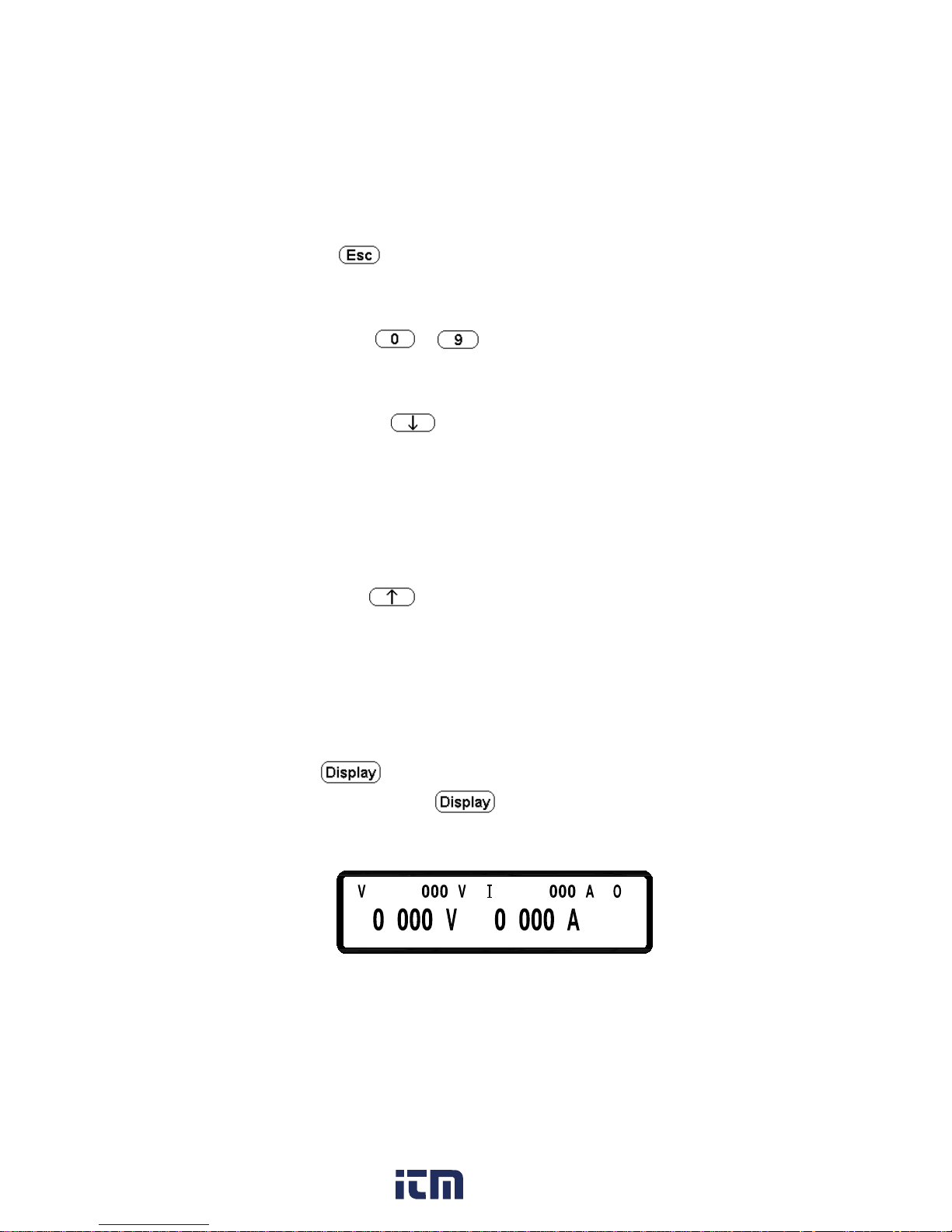
(10) Display :
In “ Menu S etting”, p ress
to return t o m ain screen or toggle
the display to show voltage an d current or power a nd load resistance as
shown below:
=36. FF
5
1
.
=
.
.
www. .com
information@itm.com1.800.561.8187
Page 21
14
.
1= .
5
FF
.
3=6
.
(11) Output :
Control the On/Off of the output power.
(12) The rotary knob:
Use t his knob to ad just v oltage o r cu rrent ( press
first t o le t
cursor display first). This is adjustable when output is ON.
(13) Enter
:
This ke y is the c onfirmation key o f c urrent or vo ltage s etting va lue; o r
press
under ou tput s tatus t o dy namically a djust v oltage ( at C V
mode) or current (at CC mode).
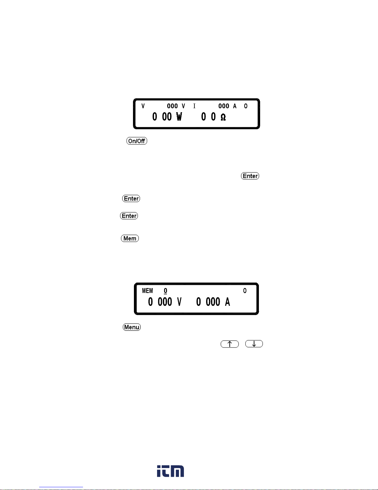
(14) Mem
:
Press this key to enter access the storage memory. Users can then use the
numerical key or knob to select the target m emory set to s ave o r recall
the configuration by pressing t he STORE or RECALL k ey. Ten sets are
available in selection.
=
FF
.
.
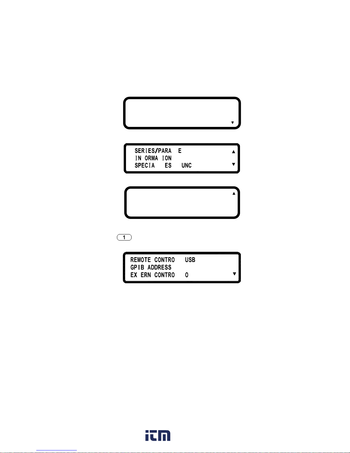
(15) Menu :
Use this key to enter system parameter settings. There are eight (8) major
items unde r ope ration. Users m ay press
,
to scr oll
through t he m enu list or the num erical k eys to enter the corresponding
item number in the menu list.
www. .com
information@itm.com1.800.561.8187
Page 22
15
.
4
5
6
.
.
F
LL L
T
L T T F
1. SYSTEM SETTING:
Pressing
key i n t he f irst pa ge of Menu S etting will e nter the
following “SYSTEM SETTING” menu.
L=
= 1
T
=L
FF
REMOTE CONTROL:
Choose the remote interface
(USB/GPIB/ETHERNET)
*GPIB and ETHERNET available only
with on models with “-GL” suffix
*USB control requires installing USB
drivers first. Download USB driver
*US
B interface is a virtual COM port. T he settings are:
Baudrate : 57600 bps
1 . SYSTEM SETTING
2 . OUTPUT SETTING
3 . PROTECTION
7 . TIMER CONTROL
8 . CALIBRATION
9 . CHAIN SETTING
www. .com
information@itm.com1.800.561.8187
Page 23
16
Data bit : 8
Parity check : none
Stop bit : 1
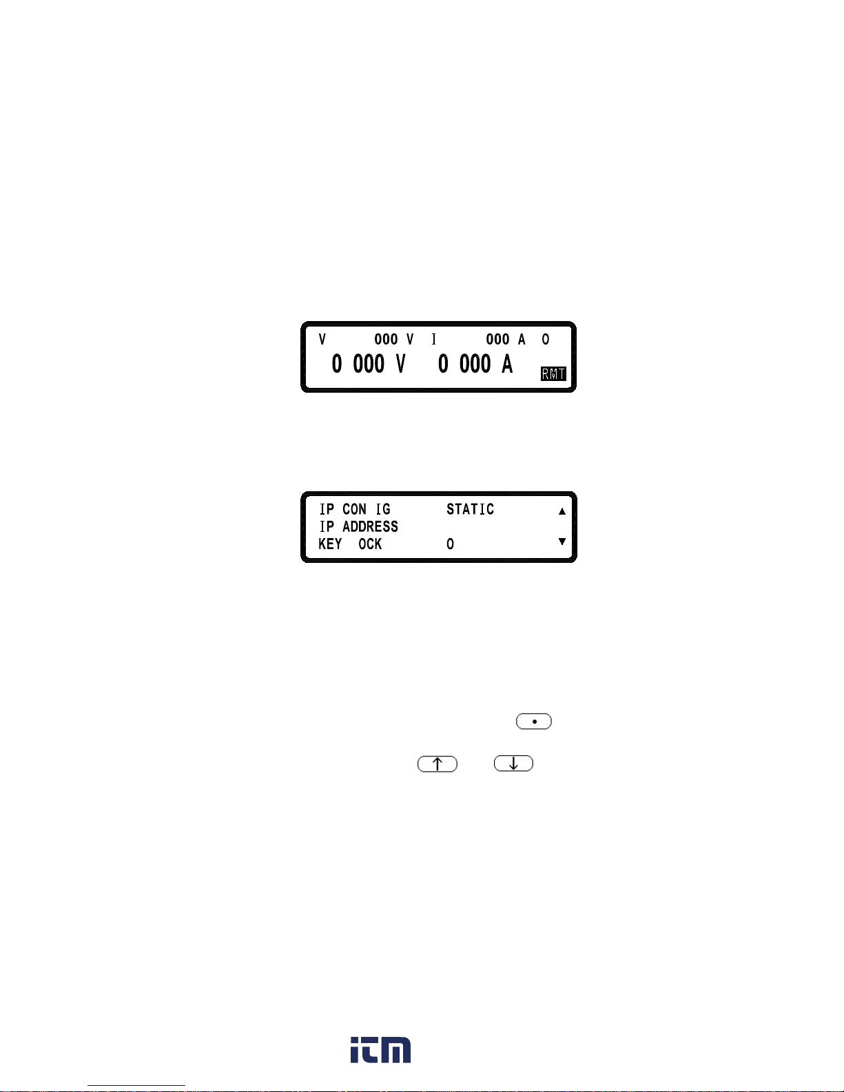
*When entering t he Remote mode, screen will present R MT indicator as
shown in the following picture.
1
.
= .
5
F
F
3
.
= .
6
GPIB ADDRESS:
Set up GPIB ADDRESS (1-30)
EXTERN CONTROL:
Set up t he external
control to voltage
control (VOLT 0-10 V or 0-5 V), res
istance
control (RES 0-5K) or off (OFF).
=
5
F
52=
= F
552. 552. 552
.
F
L
IP CONFIG:
STATIC : User can input IP address
IP ADDRESS:
If IP C ONFIG is set to S TATIC, us ers can enter
a
static IP address here.
Note:
If you are not sure of the IP settings, consult
your network administrator.
KEY LOCK:
While e xiting the s etting screen after en
able K EY
LOCK, all keys except the key
are l ocked.
Only this key can disable KEY LOCK.
*Simultaneously pressing both and keys in th e main
screen can also lock keys.
*While e ntering K EY LOCK state, sc reen w ill present LCK indicator in
the bottom right corner.
www. .com
information@itm.com1.800.561.8187
Page 24
17
L
=
F
L
L
=
=
L
L
L
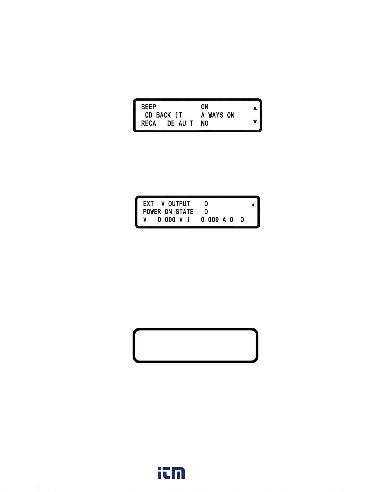
BEEP:
Turns the Buzzer ON/OFF
LCD BACKLIT:
Set the backlight of the LCD to Always
ON or OFF after 1/5/10/30 minutes
RECALL DEFAULT:
Restores the manufacturer
default
settings
.
FF=
F
=
,
=.F
=,FF
5
=
Ext 5V OUTPUT:
Turns the extra 5V power output
(on the rear
panel) ON/OFF.
POWER ON STATE:
Users can set t he ou tput state
of t he supply
when powered on. When OFF is selected, the
XLN series will do nothing after power on.
If
LAST is sel ected, then a t power on
the
supply w ill
use t he last set ting b efore it
turned off previously. If USER (user defined)
is sel ected,
a p rompt w ill a sk f or setting
output voltage, current, a nd output s tate.
Once set, these values are then used the next
time the supply is powered on.
HOT KEY:
Set the HOT KEY function ON/OFF. I
f the
HOT KEY function is ON, user can use 0 –
9
number keys to recall the voltage and current
HOT KEY = OFF
www. .com
information@itm.com1.800.561.8187
Page 25
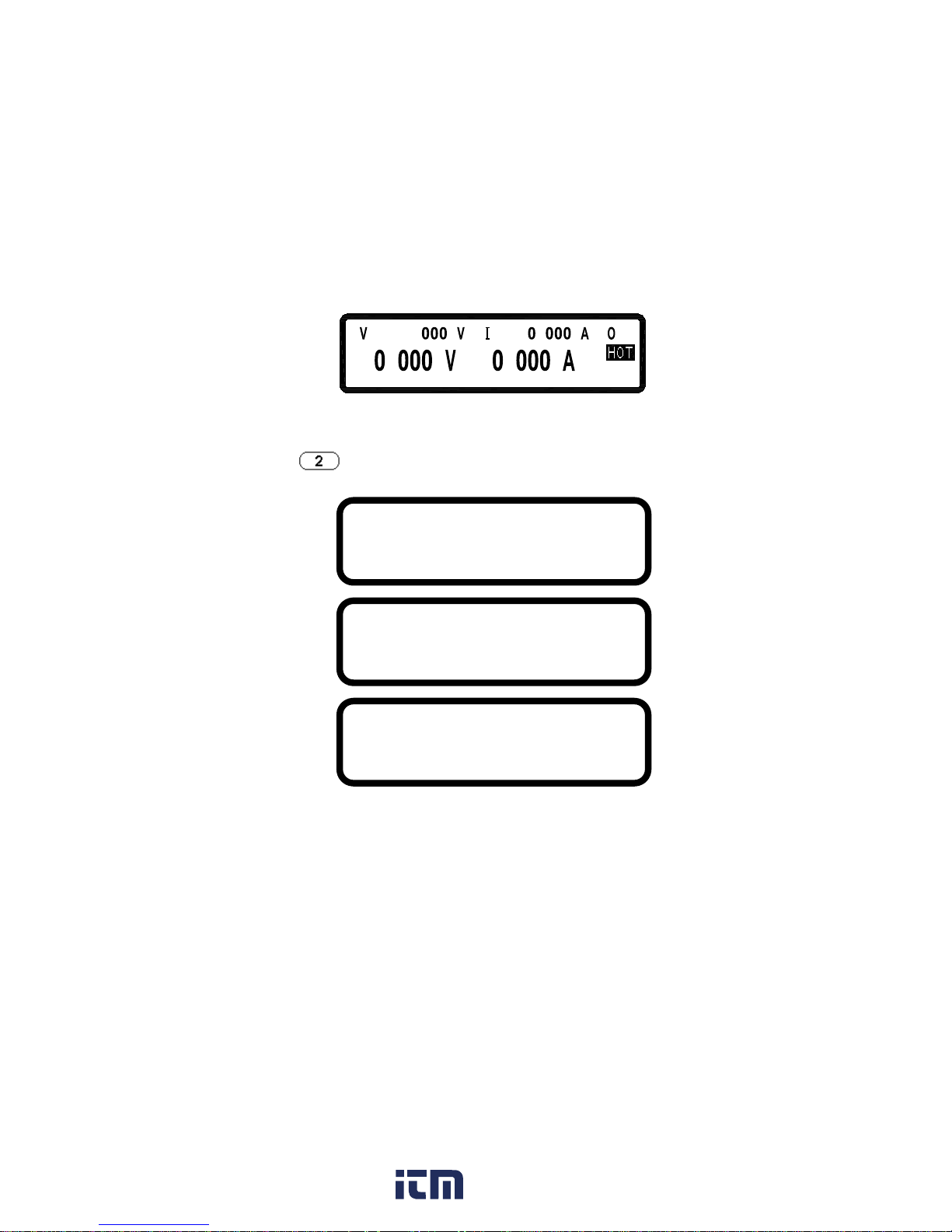
18
setting values stored inside internal memory.
*If e ntering t he HOT K EY mode, sc reen w ill indicate HOT s ymbol a s
shown in the following illustration.
6
.
=
3
.
4
.
=
.
F
F
2. OUTPUT SETTING:
Press
in the first p age o f Menu S etting t o enter OUTPUT
SETTING menu.
VOLT LIMIT:
Upper limit of the output voltage setting
CURR LIMIT:
Upper limit of the output current setting
VOLT SLEW RATE:
Voltage ascending/descending slope
(XLN3640: 0.01 - 2.4V/ms)
(XLN 6024:0.01 - 3V/ms)
(XLN 8018:0.01 - 3.2V/ms
(XLN 10014:0.01 - 3.3V/ms)
VOLT LIMIT MAX = 60.500 V
CURR LIMIT MAX = 24.500 A
VOLT LIMIT MIN = 0.000 V
CURR LIMIT MIN = 0.010 A
VOLT SLEW RA TE = 3.0000 V/mS
CURR SLEW RA TE = 1.2000 A/mS
CONNECTOR DROP = DISABLE
EXT FULL VOLT = 10 V
www. .com
information@itm.com1.800.561.8187
Page 26

19
CURR SLEW RATE:
Current ascending/descending slope
(XLN 3640:0.01 - 2.5A/ms)
(XLN 6024:0.01 - 1.2A/ms)
(XLN 8018:0.01 - 0.72A/ms
(XLN 10014:0.01 - 0.48A/ms)
CONNECTOR DROP:
Turns on/off the connector drop calibration
function
EXT FULL VOLT:
External voltage control full-scale setting.
Select between 10 V or 5 V for full-scale
control.
3. PROTECTION SETTING (PROTECTION)
Press
key in th e first screen of “Menu S etting” to e nter
PROTECTION menu.
OVP:turns on/off the
overvoltage protection
SET: set up the overvoltage protecting
point.
OCP:turns on/off the
overcurrent protection
SET:
set up the overcurrent protecting
point.
OPP:turns on/off the overpower
protection
SET: set up the overpower protecting
point.
FF
FF
=
=
CV TO CC:
Enable/disable the protection of t he change
OVP = OFF SET = 38.000 V
OCP = OFF SET = 42.000 A
OPP = OFF SET = 1440.000 W
www. .com
information@itm.com1.800.561.8187
Page 27

20
from CV to CC mode
CC TO CV:
Enable/disable the protection of th e change
from CC to CV mode
4. SERIES/PARALLEL SETTING
Press
in t he second screen of Menu S etting t o e nter
SERIES/PARALLEL menu.
L
T
L
T
FF
=
=
T
SELECT MODE: Choose
series or parallel operation
mode.
MASTER/SLAVE:
Refer to “ Series/Parallel S etting”
section
for t he d etailed setting
procedure of MASTER/SLAVE mode.
5. INFORMATION
Press
in the second screen of “Menu Setting” to enter
INFORMATION screen.
F
463L
L
:
1
31
.
L
6. SPECIAL TEST FUNCTION
Press
in the second screen of “Menu Setting” to enter SPECIAL
TEST FUNCTION menu.
1. CURRENT COUNT ER TEST
2. PROGRAM MODE
3. MEASURE AVERAGE
www. .com
information@itm.com1.800.561.8187
Page 28
21
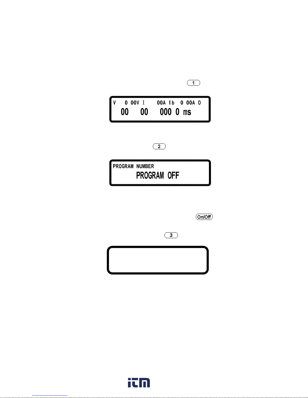
6.1 CURRENT C OUNTER T EST: Press to e nter t he
CURRENT COUNTER TEST screen.
= 1 . = .
:
.
FF
= 1 .
:
Refer to “Current Counting” section for the detailed setting procedure.
6.2 PROGRAM MODE: Press
to enter the PROGRAM MODE
menu.
1=
Before r unning t he pr ogram, us er needs t o input the p rogrammed
values through the USB or G PIB i nterface into the power su pplies.
Users may save up to 10 programs ( program number 1 t hrough 10)
inside the memory and r ecall them in this Program Mode screen by
selecting the program number and then pressing
to execute
the program.
6.3 MEASURE A VERAGE: Press
to enter th e MEASURE
AVERAGE page.
AVERAGE TIME:
Set the average measure time.
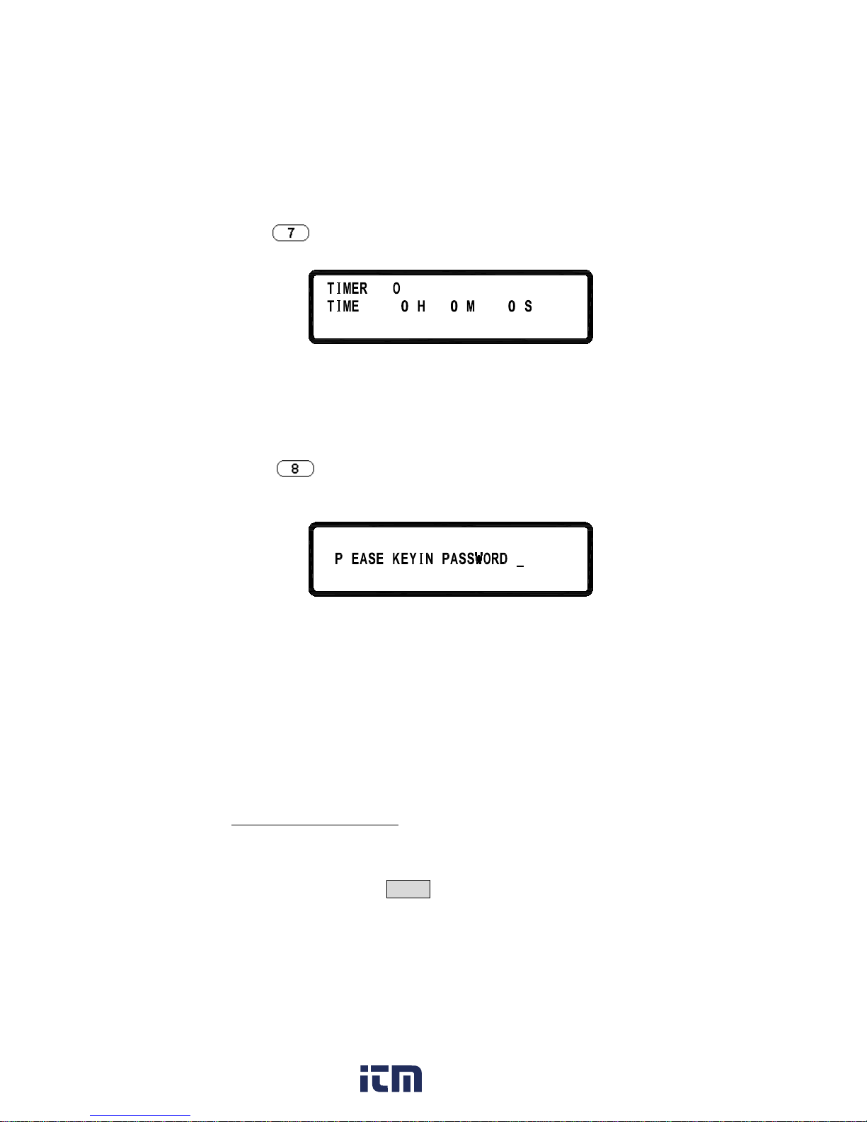
7. TIMER CONTROL
AVERAGE TIME = 2
www. .com
information@itm.com1.800.561.8187
Page 29
22
Press
in t he t hird pa ge of Menu S etting t o e nter T IMER
CONTROL screen.
=
=
FF
r
ni ec
TIMER:
Turn on/off TIMER function.
TIME:
Set up OUTPUT ON time (Max:999Hr 59Min
59Sec)
8. CALIBRATION
Press
in the t hird page of “Menu Setting” to enter
CALIBRATION menu. Users must enter t he p assword to access
calibration mode.
:
L
8.1 Equipment Requirements
1. 5 ½ Digital Volt meter.
2. Shunt for current calibration (100 A/ 10 m Ω)
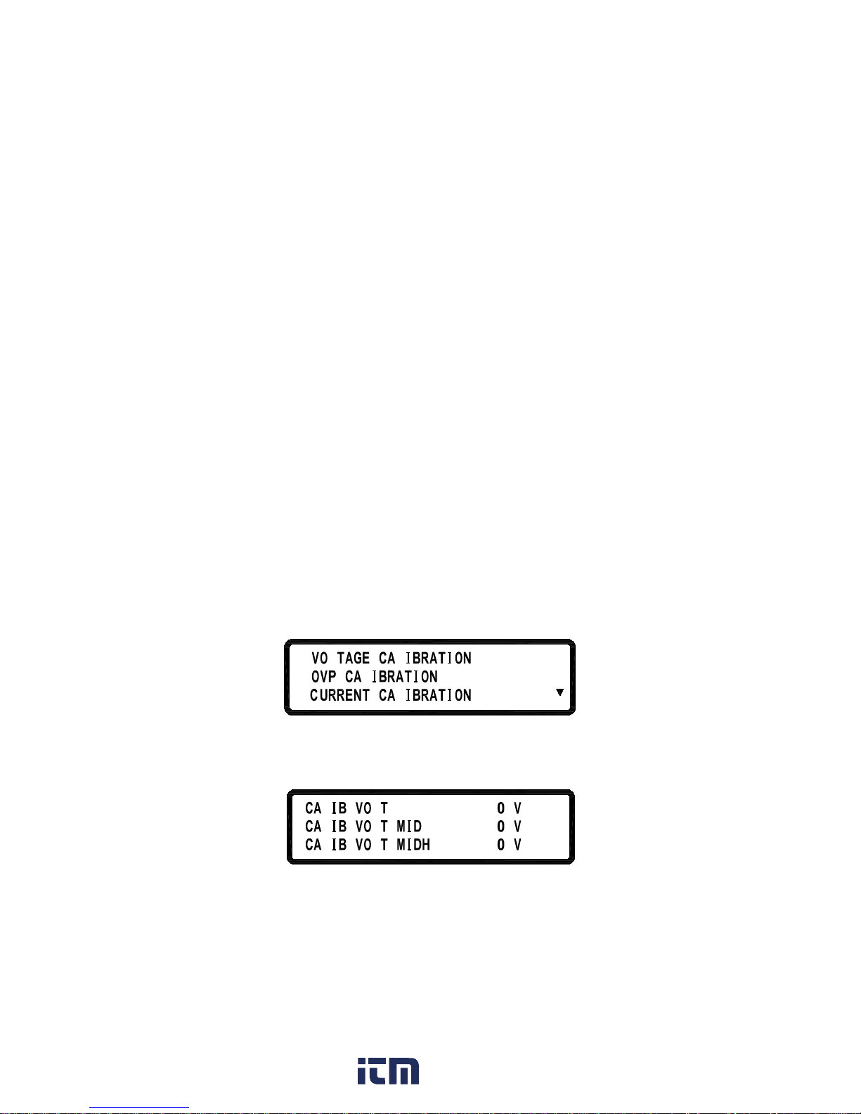
8.2 Calibration Procedure
A. Connect power s upply output t erminal to D VM (as s hown i n
Figure 1 below). Turn on the s upply. O nce the u nit enters t he
main p age, p ress MENU and se lect “8. Calibration” and ke y i n
VOLTAGE CALIBRATION
www. .com
information@itm.com1.800.561.8187
Page 30
23
password “13579” to enter the following calibration menu screen:
Figure 1
L
1
.
3
2
.
.
L
L
L
B. Press “1” to access Voltage Calibration Procedure.
C.
L
o
468.1=L
5
2
1=L
=
2 4
455
.
11L
L
L
L
L
www. .com
information@itm.com1.800.561.8187
Page 31

24
LL
i
87.53=
D. According to voltage value displayed on DVM, fill in the values
for their corresponding functions and press ENTER. If any DVM
read-back value at each voltage function does not fit with the
following table below, please inspect the hardware.
XLN3640
Function
Setting
Val ue
Range of Read-Back Value
Lo 1.8V 1.5 - 2.0 V
MIDL 12V 10 - 13 V
MIDH 24V 21 - 25 V
Hi 32.4V 31 - 34 V
XLN6024
Function
Setting
Val ue
Range of Read-Back Value
Lo
3V
2.4 - 3.6 V
MIDL
20V
18 - 22 V
MIDH
40V
36 - 44 V
Hi
57V
53 - 61 V
XLN8018
Function
Setting
Val ue
Range of Read-Back Value
Lo
4V
3.6 - 4.4 V
MIDL
26V
23.5 - 28.5 V
www. .com
information@itm.com1.800.561.8187
Page 32
25
MIDH
53V
48 - 58 V
Hi
76V
69 - 83 V
XLN10014
Function
Setting
Val ue
Range of Read-Back Value
Lo
5V
4.5 - 5.5 V
MIDL
33V
29.7 - 36.3 V
MIDH
66V
59 - 72 V
Hi
95V
85 - 104 V
E. When pressing ENTER at Hi function, and the calibration data
values will be stored in FLASH and unit will return to calibration
main screen.
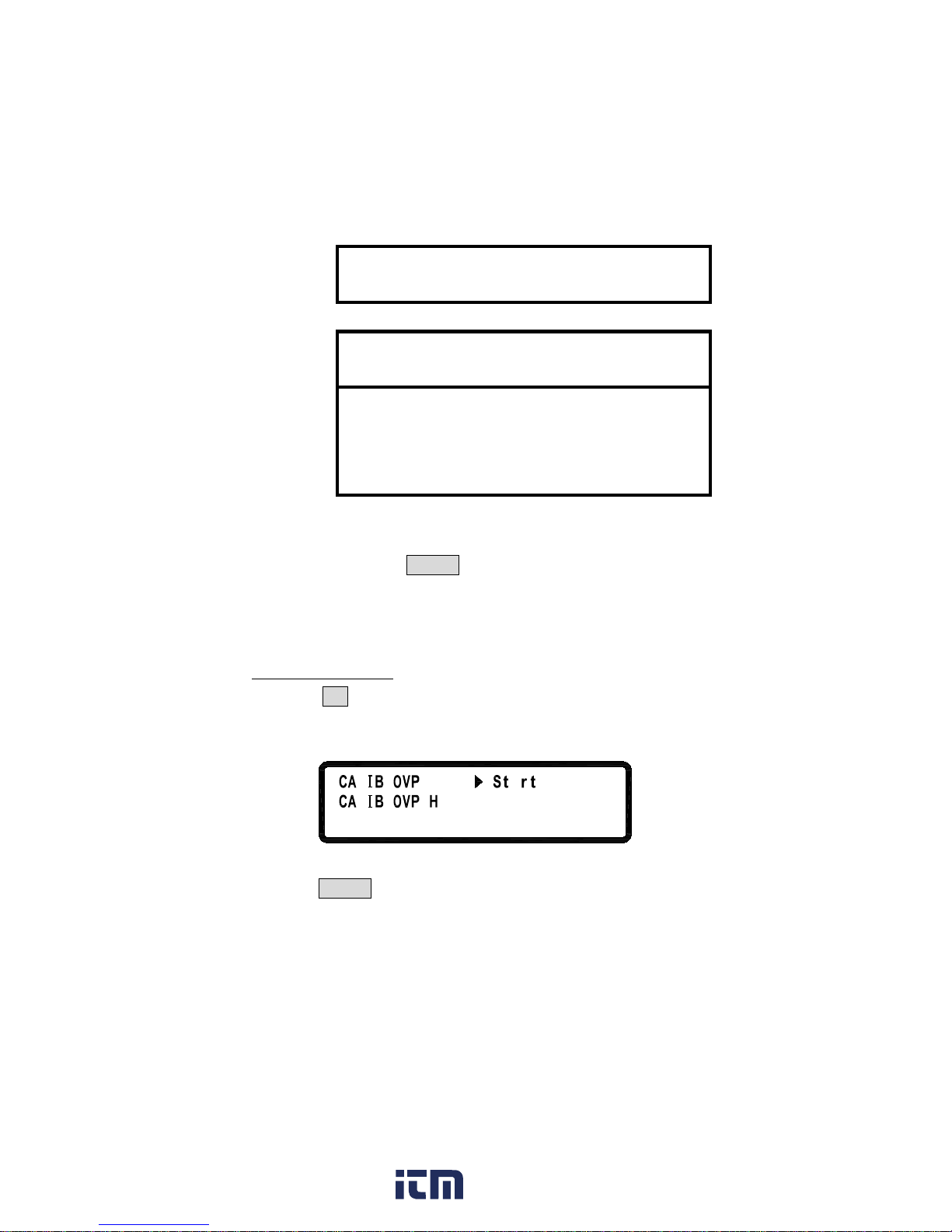
A. Press 2 in the calibration main page to enter OVP calibration
page.
OVP CALIBRATION
L
L
a=
o
L
=
i
B. Press ENTER to access OVP calibration procedure at Low function.
www. .com
information@itm.com1.800.561.8187
Page 33

26
L
L
n
i
abilaLo=
=
i
...
C. Jump to Hi function when completed.
L
L
Lo=
=
i
a
D. Press ENTER to access OVP calibration procedure at High function.
E.
L
L
Lo=
a=
i
lib
ain
. . .
F. After completing the above steps, calibration value will be stored in
FLASH and unit will return to the calibration main screen.
G. If calibration is not completed in 10 seconds after starting, please
inspect OVP circuit.
A. Connect two output terminals of the power supply to two ends of the
current shunt, and connect DVM to the sensor of current shunt to
measure DC voltage as shown Figure 2. Press 3 to enter current
calibration screen.
CURRENT CALIBRATION
B. First, input parameter (resistance of current shunt, mΩ) of current
www. .com
information@itm.com1.800.561.8187
Page 34

27
measurement fixture. According to voltage value shown on DVM,
fill in that value that corresponds to the function and press ENTER
key.
Figure 2
.
F
L
L
.
1
=
3
o
L
=
=L 1
.
1
.
www. .com
information@itm.com1.800.561.8187
Page 35

28
C. Please inspect the hardware if the current value is inconsistent with
the value in the tolerance error table below after the calibration
values of each function is changed to actual current value.
XLN3640
Function Setting Range of Transformation Value
Lo
0.1A
0 - 0.5 A
MIDL
13A
11 - 14 A
MIDH
26A
23 - 27 A
Hi
38A
34 - 39 A
XLN6024
Function Setting Range of Transformation Value
Lo
0.06A
0 - 0.5 A
MIDL
7.8A
6.6 - 9 A
MIDH
15.6A
14 - 17.2 A
Hi
22.8A
21 - 24.6 A
XLN8018
Function Setting Range of Transformation Value
Lo 0.045A 0 - 0.1 A
MIDL 5.9A 5.3 - 6.5 A
MIDH 12A 10.8 - 13.2 A
Hi 17A 15.3 - 18.7 A
CALIB CURR MIDH = 258.246 mV
CALIB CURR Hi = 377.559 mV
www. .com
information@itm.com1.800.561.8187
Page 36

29
XLN10014
Function Setting Range of Transformation Value
Lo
0.03625A
0 - 0.1 A
MIDL 4.7A 4.2 - 5.2 A
MIDH 9.5A 8.55 - 10.45 A
Hi 13.7A 12.33 - 15.07 A
D. The calibration value will be stored in FLASH after pressing
ENTER at Hi function.
9. Series Connection Control Setting (CHAIN)
Press
in Menu setting page to enter CHAIN SETTING
page.
FF=FF
1=
CHAIN ON/OFF : On/Off Series Connection Mode
CHAIN ADDRESS : Setting Address (1 – 30)
For the detailed setting information, please refer to “SERIES
CONNECTION FUNCTION” section.
www. .com
information@itm.com1.800.561.8187
Page 37

30
3.1.2 Rear Panel
Cooling fans:
The supply automatically adjusts fan’s rpm according to the load condition.
(16) Cooling fan:
The rear cooling fan speed is temperature control.
(17) Power output terminal:
Please pay attention to the correct polarities when making connection.
(18) RMT/LCL Sense:
When Remote s ense is sel ected, the w ire connection can be setup as
follows (shown i n t he f igure below): positive s ense (+S) and positive
lead ( +) of the D C output a re c onnected to t he positive end (+) of the
device, whereas negative sense (-S) and negative lead ( -) of the D C
output are connected to the negative end (-) of the device under test. This
connection w ill c ompensate the v oltage dr opped du e t o c urrent f low
through long power wires (the maximum compensation voltage is 2 V).
16
17
18
19
20
21
22
23
24
25
26
www. .com
information@itm.com1.800.561.8187
Page 38

31
When L ocal sense is se lected, the w ire connection can be setup as
follows (shown i n t he figure a bove):positive sen se (+S) is connected t o
the positive lead (+) and negative sense (-S) is connected to the negative
lead ( -), w hereas the p ositive l ead (+) of the D C output is connected t o
the p ositive e nd (+) of the de vice a nd the negative lead ( -) of the D C
output is connected to the negative end (-) of the device under test. When
this sensing mode is selected, the power wires from the DC output leads
to the device under test should be as short as possible.
(19) LAN (optional):
The ETHERNET interface connector
(20) GPIB (optional):
The GPIB interface connector
(21) AC power input:
The power receptacle is for a power source within 100 VAC - 240 VAC.
(22) Earth connection:
Used for earth ground connection.
www. .com
information@itm.com1.800.561.8187
Page 39

32
(23) 5V/1A Output:
XLN series offers an extra output with a constant ou tput voltage of 5 V
and the maximum output current of 1 A. This extra power supply can be
switched on or off under the “System Setting” menu.
(24) USB :
USB interface connector.
(25) EXT CTL:
Models XLN3640/XLN6024/XLN8018/XLN10014 offer t he capability
of setting t he out put v oltage/current by adjusting an external input
voltage/resistance. The range of the external input voltage is 0 - 10 VDC
or 0 - 5 VDC, which c orresponds to t he o utput voltage of 0 - 36 V for
XLN3640, 0 - 60 V for XLN6024, 0 - 80 V for XLN8018, and 0 - 100 V
for XLN10014 and corresponding to the output current of 0 - 40 A for
XLN3640, 0 - 24 A for XLN6024, 0 - 18 A for XLN8018, and 0 - 14.4 A
for XLN10014. The r ange of the external resistance i s 0 - 5 K ohm
which corresponds to the output v oltage of 0 - 36 V for XLN3640, 0 60V for XLN6024, 0 - 80 V for XLN8018, and 0 - 100 V for XLN10014
and corresponding to the output current of 0 - 40 A for XLN3640, 0 - 24
A for XLN6024, 0 - 18 A for XLN8018, and 0 - 14.4 A for XLN10014.
(26) RS485:
While in series or parallel c onnection or mu lti-unit series connection
(CHAIN), RS485 interface can be used f or communication and
synchronization between master and slave.
(27) Protection cover of the RMT/LCL Sense connector
(XLN6024/XLN8018/XLN10014):
WARNING:
When the RMT/LCL Sense is not activated and/or not
used, the protection cover must be covered
. T o prevent
electric shock, do not dissemble this protective cover.
(28) Protection cover of the output leads
(XLN6024/XLN8018/XLN10014):
www. .com
information@itm.com1.800.561.8187
Page 40

33
WARNING:
This PRODUCT is designed meeting safety code and has
passed the related qualification test. In case no output
cable is connected, close the protection cover and fasten
the screws in so as to protect user from electric shock or
other hazards.
www. .com
information@itm.com1.800.561.8187
Page 41

34
4. Operation Instructions
4.1 Voltage Setting
Press
and set the output voltage by pressing the numerical keys directly,
and then press
to confirm the setting.
=
.
.
=
1
5
.
FF
4.2 Current Setting
Press
and set the output current by pressing the numerical keys directly
and then press
to confirm the setting.
=
.
FF.
63
=
.
4.3 Over-voltage Protection OVP
Press
to e nter the C onfiguration menu and p ress to enter the
PROTECTION setting menu. Then, using the knob set OVP t o ON and press
to c onfirm i t. N ow t he c ursor w ill m ove t o t he value setting for t he
OVP on t he right hand side. Enter the OVP value h ere by pressing the
numerical keys.
F
F
S
=
3
.
8
S
S
=
=
204
41 4
.
.
F
F
=
=
=
4.4 Over-current Protection OCP
Press
to enter the “Configuration” menu and press to enter the
PROTECTION setting screen. Then, use the knob to set OCP to ON and press
www. .com
information@itm.com1.800.561.8187
Page 42

35
to confirm i t. N ow t he c ursor w ill m ove t o the value setting for t he
OCP on the right hand side. Enter th e O CP v alue by pr essing the n umerical
keys.
F
=
=
=
F
8
.
3
=
S
S
S
=
=
02441 4
.
.
4.5 Voltage Output
After the voltage, current and protection settings are entered, press
to
output voltage. User will be able to recognize the setting values and the actual
output values from the LCD.
.
=
1
5
.
.
63
=
.
4.6 Control Voltage Output with Rotary knob
When the output is ON, user may still increase or decrease the out put voltage
by turning the rotary knob. The p rocedure i s: press
and c ursor
appears i n r esponse; p ress
or
to m ove the cursor to th e d igit
you want to change and turn the knob to increase or decrease the output voltage
value a t the c ursor. The changes o f t he v oltage setting a nd t he output voltage
can be observed.
.
= 1
5
.
.
63
=
.
4.7 Timer Function
When the “Timer S etting” f unction i s O N, i t w ill activate th e t imer. After
timer setting i s m ade, r eturn t o t he m ain screen. A fter s etting up the ou tput
current & v oltage and press to ou tput, the screen will s how t he
www. .com
information@itm.com1.800.561.8187
Page 43

36
countdown of the timer. Once it reaches down to zero, the supply will turn off
the output automatically.
=
.
ce55
:
:
.
4.8 Series (cascade) / Parallel Mode Setting
The XLN3640/XLN6024/XLN8018/XLN10014 uses t he se ries/parallel m ode
(4 supplies maximum) to increase the output power capability. By connecting 4
instruments in parallel, the combined unit can offer 36 V/160 A pow er output.
By c onnecting 4 XLN10014 units in se ries, t he combined supply can output
400 V/14.4 A. Note that you c annot pe rform bot h pa rallel and series mode at
the s ame time. Series c onnection will be off o nce series (cascade) / p arallel
connection function is turned on.
4.8.1 Parallel Connection Setting
While c onnecting f our s ets of XLN3640/XLN6024/XLN8018/XLN10014 in
parallel, the wiring should be setup like the following:
After w iring i s complete, configure one XLN3640 / XLN6024 / XLN8018 /
XLN10014 as the Master and the other three are Slave A, B and C. After one of
the supplies is configured to be the Master, it will start searching for all Slaves
www. .com
information@itm.com1.800.561.8187
Page 44

37
that are connected to the Master. Therefore, in order to correctly configure the
correctly, user must set up the Slaves
before
To set a XLN3640/XLN6024/XLN8018/XLN10014 to slave mode, p ress
the Master is set.
,
, and
in t he m ain screen to en ter the se ries/parallel
setting op tion. And t hen select the p arallel m ode by turning the k nob (SCPI
command is “PS:MODE PARALLEL”) and then press
to c onfirm. It
will continue to the next line f or the MASTER/SLAVE selection. Turning the
knob t o select SLAVE A (SCPI c ommand i s “ PS:TYPE SLA VEA”) for the
supply and pr ess
to c onfirm t he s etting. Using the sam e p rocedure,
setup SLAVE B and C for another two (2) supplies as shown below.
L
LL
=
=
L
L
L
To s et the master unit, pr ess
,
, and
in t he main screen
to en ter the series/parallel setting option. And then use t he k nob t o select the
parallel mode (SCPI command is “PS:MODE PARALLEL”) and press
to confirm. It will continue to the next line for the MASTER/SLAVE selection.
Use knob again to select MASTER (SCPI command is “PS:TYPE MASTER”)
and t hen press
to confirm. A fter i t is co nfirmed as t he Ma ster the
XLN3640/XLN6024/XLN8018/XLN10014 will start sea rching f or al l S laves,
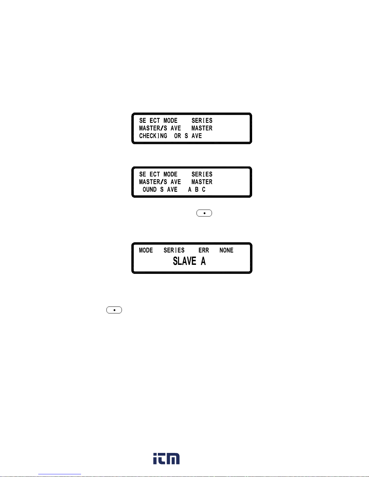
as shown below:
= LL L
=
F L
...
L
L
If wiring is correct, screen will appear as:
L
= LL L
=
:
L
L
F
www. .com
information@itm.com1.800.561.8187
Page 45

38
After receiving the control command from the Master, all Slaves will be locked
on to the SLAVE screen. At t his poi nt all k eys e xcept
are locked so
that slaves cannot be operated by front keys except controlled by the Master as
shown below:
:
:
LLL
Once the Master and Slave settings are done, users can then operate the Master
only to set up the combined output voltage and current of the complete system.
To release from this operation mode (parallel operation mode in this example),
press
(LCL) t o access to the series/parallel setting screen and turn the
knob to select O FF for series/parallel selection to disable the series or parallel
operation m ode a nd return to the l ocal o peration mode so that th e
XLN3640/XLN6024/XLN8018/XLN10014 can be controlled by press the front
keys again. Do not change t he o peration m ode w hile
XLN3640/XLN6024/XLN8018/XLN10014 is in t heir output states or there w ill
be a Master’s co mmunication failure an d an error message w ill b e d isplayed.
After power-off, if you want to keep the previous series/parallel setting, please
turn on the Slave first. Then turn on the Master.
4.8.2 Series Mode Setting
While c onnecting f our s ets o f XLN3640/XLN6024/XLN8018/XLN10014 in
series, the wiring setup should be configured as shown:
www. .com
information@itm.com1.800.561.8187
Page 46

39
After w iring i s c omplete, configure one supply as t he Master an d the o ther
three as the Slave A, B, and C. After the power supply is configured as Master,
it will start searching for all Slaves that are connected to the Master. Therefore,
in order to setup correctly, user must set up the Slaves
before
To s et a XLN3640/XLN6024/XLN8018/XLN10014 to th e slave mode, p ress
the Master is set.
,
, and
in t he m ain screen to en ter the se ries/parallel
setting o ption. Then select the SERIES mode by turning the k nob (SCPI
command is “P S:MODE SERIES”) and t hen press
to c onfirm. It will
continue to the next line for the MASTER/SLAVE selection. Turn the knob to
select S LAVE A ( SCPI command i s “P S:TYPE SLAVEA”) for the instrument
and pr ess
to c onfirm t he setting. Using the same p rocedure to se t u p
SLAVE B and C for the other two supplies.
L
L
=
=
L
To s et the master unit, press
,
,
and
in the main screen to
enter the ser ies/parallel set ting option. Then use the k nob to select the series
mode (SCPI command is “PS:MODE SERIES”) and press
to confirm.
It w ill c ontinue to the next l ine for the MASTER/ S L AV E selection. Use knob
again t o select MASTER (SCPI co mmand i s “PS:TYPE MASTER”) and then
press
to c onfirm. A fter c onfirming t he s upply as the Ma ster, it will
www. .com
information@itm.com1.800.561.8187
Page 47
40
start searching for all Slaves, as shown below.
=
=
F
L
.. .
L
L
If wiring is correct, this screen will appear:
L
=
=
:
L
L
F
After receiving the control command from the Master, all Slaves will be locked
on t he SLAVE screen and all k eys ex cept
are disabled so t hat s laves
cannot be operated by pressing front keys. This ensures the Master supply be
in control.
::
Once the Master and Slave settings are done, users can then operate the Master
only to set up the output voltage and current.
To release from this operation mode (series operation mode in this example),
press
(LCL) to access to the series/parallel setting screen and turn
the knob to select OFF for series/parallel selection to leave the series or
parallel operation mode and return to the local operation mode so that the
power supply can be controlled by pressing the front keys again. Do not
change the operation mode while the instruments are in their output state or
they will cause the Master’s communication to fail and display an error
message. After power-off, if you want to keep the previous series/parallel
setting, please turn on the Slave first. Then turn on the Master.
www. .com
information@itm.com1.800.561.8187
Page 48

41
4.8.3 Error Message of Series/Parallel Connection
If the RS485 w iring i s wrong or th e s ignal is not correct, the Master w ill
display the following message in the screen for searching Slaves:
L
L
LL
=
=
:
L
L
F
If more than one Master is being set in the series/parallel operation mode, the
following message will be displayed.
L
L
L
=
LL
L
=
,
L
If one of the pow er supplies is set to different series/ parallel operation mode,
the following message will appear on-screen:
L
L
L
LL
=
=
,
L
After f inishing se tting p rocedure, if t he Master cannot ha ve a communication
with one o f t he t hree Slaves, the Master w ill p resent t he f ollowing e rror
message (Slave A in this example).
L
!!!
After finishing the setting p rocedure, i f a Slave receives only the ou tput
command sent by the Master but does not receive the synchronization signal, it
will p resent the following error m essages. The e rror m essage “SYNC ON” is
shown when the slave is not receiving t he synchronous output ON signal. The
www. .com
information@itm.com1.800.561.8187
Page 49

42
error m essage “SYNC OF F” is s hown w hen the s lave is no t receiving th e
synchronous output OFF signal.
LL L
::
4.9 External Tuning Setting
Models XLN3640/XLN6024/XLN8018/XLN10014 provides the c apability to
control the ou tput v oltages by an external voltage/resistance. The range of the
external voltage is in 0 - 10 VDC or 0 - 5 VDC and the range of t he external
variable resistance is between 0 - 5 kΩ to control the output v oltage (0 - 36 V
for XLN3640, 0 - 60 V for XLN6024, 0 - 80 V for XLN8018, and 0 - 100 V for
XLN10014) and the o utput current (0 - 40 A for XLN3640, 0 - 24 A f or
XLN6024, 0 - 18 A for XLN8018, and 0 - 14.4 A for XLN10014). The wirings
of the external control are shown in the following figure.
The external v oltage c ontrol o r e xternal r esistance c ontrol can b e se t in the
“system set ting” screen. Since th e e xternal control circuit uses a 12bit D /A
converter for 0 - 36 V for XLN3640 (or 0 - 60 V for XLN6024 or 0 - 80 V for
XLN8018 o r 0 - 100 V fo r XLN10014) output v oltage a nd 0 - 40A for
www. .com
information@itm.com1.800.561.8187
Page 50

43
XLN3640 (or 0 - 24 A for XLN6024 or 0 - 18 A for XLN8018 or 0 - 14.4 A for
XLN10014) output c urrent, the resolution o f v oltage a nd c urrent w ill b e
different in response. The screen will show similar to the following (accuracy is
10mV):
4.10 Timer of Current Flow
This function of fers testing of the c utoff time o f a breaker o r a fuse. First,
connect the test object to output terminal as shown below.
Press
,
,
and then
in the main screen to enter the current
flow counter screen.
= 1. = .
:
.
FF= 1 .
:
Press VSET to set the voltage. Then press ISET to set the current (I), which is
the m aximum cu rrent y ou w ant t o t est. P ress ISET t wice t o set the
breaker/fuse cu rrent ( Ib). A fter s etting up the output voltage/current and
pressing
to turn on t he output, the system w ill st art co unting down
the timer until the breaker or fuse is open. The count starts from when output
has reached the Ib current. The resolution of the timer is 100us (0.1 ms) and
the maximum c ounting period is on e hou r. I f the counter d oesn’t w ork a fter
V = 36.00 V
I = 40.00 A OFF
0.00 V 0.00 A
www. .com
information@itm.com1.800.561.8187
Page 51

44
pressing , e rror oc curs h erein a nd the screen will d isplay an error
message after two seconds. One of the following three scenarios may happen:
A. Connector not ready
If a f use is not properly connected to the ou tput c onnector or a breaker under
test has no t be en s witched t o O N po sition, t he screen w ill show a n e rror
message as shown below.
LF !:!
:
.
!
B. Current setting too large
The output current is set too big that a breaker is open or a fuse is burnt to open
before out put current i s reaching t he s etting v alue. The screen w ill sh ow a n
error message as shown below.
!F L:! L
:
.
!
C. Voltage setting too small
The voltage is set too small, therefore the output current is unable to reach the
setting value. The screen will show an error message as shown below.
LF !:!
:
.
LL !
4.11 Programmable Capability (SCPI Command Only)
Models XLN3640/XLN6024/XLN8018/XLN10014 provides the c apability to
support list mode, which allows users to download a small program to internal
memory a nd execute a program from t here. There are memory spaces to store
www. .com
information@itm.com1.800.561.8187
Page 52

45
10 programs that can have 150 steps in total for setting purpose. This can only
be pr ogrammed r emotely via U SB, G PIB, or L AN with S CPI c ommands o r
with the included software. Each program doe s not restrict the step quantity,
however, the sum of 10 programs are restricted to 150 steps. For each program
users can se t u p h ow m any t imes t o repeat the pr ogram. For each st ep u sers
may be able t o set up t he output voltage, current, and pe riod of time ( 50 ms
minimum) t o st ay o n t he st ep. Please refer t o “SCPI co mmand su bsystem”
section for detail SCPI commands.
Below are some examples of commands used to setup a custom program in list
mode.
Example 1:
To ou tput t he w ave f orm shown above, users m ay ed it the program as the
following orders:
PROG 1
Choose program number
PROG:CLE
Clear program 1 data
PROG:REP 0
No repeat (repeat one time for “1”)
PROG:TOTA 8 Set program 1 to have 8 steps in total
PROG:STEP 1
Following 3 settings are for step 1
PROG:STEP:CURR 1
Set output current to 1 ampere
PROG:STEP:VOLT 5
Output voltage is set to 5 volts
PROG:STEP:ONT 0.1 Output ON time is set to 0.1 sec
PROG:STEP 2 Following 3 settings are for step 2
PROG:STEP:CURR 1
PROG:STEP:VOLT 10
www. .com
information@itm.com1.800.561.8187
Page 53

46
PROG:STEP:ONT 0.1
PROG:STEP 3 Choose step 3
PROG:STEP:CURR 1
PROG:STEP:VOLT 15
PROG:STEP:ONT 0.1
PROG:STEP 4 Choose step 4
PROG:STEP:CURR 1
PROG:STEP:VOLT 20
PROG:STEP:ONT 0.1
PROG:STEP 5
Choose step 5
PROG:STEP:CURR 1
PROG:STEP:VOLT 15
PROG:STEP:ONT 0.1
PROG:STEP 6
Choose step 6
PROG:STEP:CURR 1
PROG:STEP:VOLT 10
PROG:STEP:ONT 0.1
PROG:STEP 7
Choose step 7
PROG:STEP:CURR 1
PROG:STEP:VOLT 5
PROG:STEP:ONT 0.1
PROG:STEP 8 Choose step 8
PROG:STEP:CURR 1
PROG:STEP:VOLT 0
PROG:STEP:ONT 0.1
PROG:NEXT 0
Select next program to r un a fter
program 1 is complete, 0 means stop
PROG:SAV
After edit, use Save command to store
program 1 in the hardware
PROG 1
PROG:RUN ON
To run the pr ogram s tored in t he
hardware, select program
number a nd
then us e RUN ON c ommand t o
execute the program.
www. .com
information@itm.com1.800.561.8187
Page 54

47
Example 2:
To out put t he w ave f orm s hown a bove, the f ollowing example program can
be used.
PROG 2
Choose program number
PROG:CLE
Clear program 2 data
PROG:REP 0
No repeat after running this program
PROG:TOTA 8
Set program 2 to have 8 steps in total
PROG:STEP 1
Settings for step 1
PROG:STEP:CURR 2
Set output current to 2 amperes
PROG:STEP:VOLT 20
Set output voltage to 20 volts
PROG:STEP:ONT 0.5
Set output ON time to 0.5 sec
PROG:STEP 2
Choose step 2
PROG:STEP:CURR 2
PROG:STEP:VOLT 15
PROG:STEP:ONT 0.5
PROG:STEP 3
Settings for step 3
PROG:STEP:CURR 2
PROG:STEP:VOLT 20
PROG:STEP:ONT 0.5
PROG:STEP 4
Choose step 4
PROG:STEP:CURR 2
PROG:STEP:VOLT 10
PROG:STEP:ONT 0.5
PROG:STEP 5
Choose step 5
PROG:STEP:CURR 1
PROG:STEP:VOLT 20
PROG:STEP:ONT 0.5
PROG:STEP 6
Choose step 6
www. .com
information@itm.com1.800.561.8187
Page 55

48
PROG:STEP:CURR 2
PROG:STEP:VOLT 5
PROG:STEP:ONT 0.5
PROG:STEP 7
Choose step 7
PROG:STEP:CURR 2
PROG:STEP:VOLT 20
PROG:STEP:ONT 0.5
PROG:STEP 8
Choose step 8
PROG:STEP:CURR 2
PROG:STEP:VOLT 0
PROG:STEP:ONT 0.5
PROG:NEXT 0
Select next program to run after
program 2 is complete, 0 means stop
PROG:SAV
After edit, use Save command to store
program 2 in the hardware
PROG 2
PROG:RUN ON
To run the program stored in the
hardware, select program number and
then use RUN ON command to
execute the program.
www. .com
information@itm.com1.800.561.8187
Page 56

49
Example 3:
If i t n eeds t o execute P rogram 2 r ight af ter P rogram 1 i s ex ecuted then
program 1 s hall be modified to have NEXT 2 command. The following steps
can be taken for the modification and execute the programs.
PROG 1 Select program 1
PROG:NEXT 2 Change the NEXT command from
NEXT 0 to NEXT 2
PROG:S AV After edit is complete use Save
command to store changes in the
hardware
PROG 1
PROG:RUN ON
To run the program, select the
program
number first and then use RUN ON
command to execute it.
www. .com
information@itm.com1.800.561.8187
Page 57

50
4.12 Multi-unit Connection mode (RS485)
XLN3640 / XLN6024 / XLN8018 / XLN10014 c an us e R S485 to p rovide
multi-units series connection function for up to 30 units (If more than 10 units,
please ad d a 120Ω resistor t erminator in t he l ast un it a s s hown i n t he be low
figure. Turn on the system after series connection i s completed. Press
on t he main page and s et CHAIN ON/OFF t o ON ( Series/Parallel
connection will be cancelled) and set each unit with a different Address (1 - 30).
Then by using USB connected to PC, multiple units can be controlled by using
the commands in “SERIES CONNECTION COMMAND LIST” section below.
SERIES CONNECTION COMMAND LIST
The series connection command used by all XLN series power supplies
use a ca rriage r eturn ( CR) ch aracter f or t ermination o f al l A SCII st rings.
For example, the system w ill respond with the corresponding value or string
when delivering the inquire command, or respond “OK” when delivering the
setting command. In case any errors happen, the system will respond with an
error message. (Please refer to ERROR RESPONSE LIST section).
www. .com
information@itm.com1.800.561.8187
Page 58

51
SYSTEM CONTROL COMMAND:
Command Description
==================================================
CADR followed by address, which can be 1 to 30 and
is used to access the power supply
CCLS Clear status
CRST Reset command. Brings the power supply to a
known state
CIDN? Returns the power supply model identification
CREV? Returns the firmware version
CSN? Returns the serial number
CST? Returns the device status
CCLR? Clear protect
==================================================
OUTPUT CONTROL COMMAND:
Command Description
==================================================
CPV Sets the output voltage value in Volts
CPV? Reads the output voltage setting
CMV? Reads the actual output voltage
CPC Sets the output current value in Amperes
CPC? Reads the output current setting
CMC Reads the actual output current
CDVC? Display voltage and current data
COUT Turns the output to ON or OFF
COUT? Returns the output On/Off status
COV Sets the OVP level
COV? Returns the OVP setting level
COVP Sets the OVP on/off
COVP? Returns the OVP on/off
COC Sets the OCP level
www. .com
information@itm.com1.800.561.8187
Page 59

52
COC? Returns the OCP setting level
COCP Sets the OCP on/off
COCP? Returns the OCP on/off
COP Sets the OPP level
COP? Returns the OPP setting level
COPP Sets the OPP on/off
COPP? Returns the OPP on/off
CMODE? Returns the power supply operation mode
==================================================
SYNCHRONOUS CONTROL COMMAND:
Command Description
==================================================
GRST Reset command. Brings the power supply to a
known state
GCLS Clear status
GCLR Clear protect
GPV Sets the output voltage value in Volts
GPC Sets the output current value in Amperes
GOUT Turns the output to ON or OFF
GOV Sets the OVP level
GOVP Sets the OVP on/off
GOC Sets the OCP level
GOCP Sets the OCP on/off
GOP Sets the OPP level
GOPP Sets the OPP on/off
==================================================
EXAMPLES:
Q1. How to read back ID for Address 5 on the system?
CADR 5 OK
CIDN? B&K Precision. XLN 3640,A1234567,1.15,0
Q2. How to set up Voltage for Address 7 on the system?
www. .com
information@itm.com1.800.561.8187
Page 60

53
CADR 7 OK
CPV 20 OK
Q3. How to set up Output for Address 7 on the system?
CADR 3 OK
COUT 1 OK
Q4. How to read back Voltage value for Address 1 on the system?
CADR 1 OK
CMV? 10.001
Q5. How to set up Current for all the systems?
GPC 5 No response
Q6. How to set up Output for all the systems?
GOUT 1 No response
ERROR RESPONSE LIST
If PC delivers an error command or connection fails, a return string will be sent
and is described below:
String Description
===============================================
OK No error
Time out Wait response time out
Range error Input value is out of range
Multi master There are more than one controller in the whole system
www. .com
information@itm.com1.800.561.8187
Page 61

54
5. Protection and Error Messages
5.1 Over-voltage Protection (OVP)
When t he OVP is activated and voltage measured exceeds the setting point of
protected v oltage, the system will e nter the “Over Voltage P rotect” mode that
will shut o ff t he output and show O VP on t he display. P ress to reset
the protection mode and deactivate the buzzer.
=36.
.
=
.
4
0
.
FF
5.2 Over-current Protection (OCP)
When t he OCP i s activated an d cu rrent measured exceeds the setting point of
protected current, system will enter the “Over Current Protect” m ode that will
shut of f t he out put and show O CP on t he display. P ress
to reset the
protection mode and deactivate buzzer.
.
63
=
.
1
0
.=
.
FF
5.3 Overpower Protection (OPP)
When the O PP i s a ctivated a nd pow er measured exceeds the se tting point of
protected p ower, sy stem w ill en ter t he “O ver P ower Protect” m ode that w ill
shut of f the output and display OPP on the screen. P ress to reset th e
protection mode and deactivate buzzer.
.
63
=
.
1
0
.=
.
FF
www. .com
information@itm.com1.800.561.8187
Page 62

55
5.4 Constant Voltage Protection (CV TO CC)
When this function is activated, the power supply will stay in CV mode. If load
changes force the system to transition from CV to CC (constant current) mode,
the system will enter the “CV TO CC Protect” state that will shut off the output
and d isplay t he C VC m essage o n the screen. P ress
to r eset th e
protection and deactivate the buzzer.
5.5 Constant Current Protection (CC TO CV)
When this function is activated the power supply will stay in CC mode. If load
changes forces t he transition from CC to CV (constant v oltage) m ode, the
system will en ter t he “CC TO C V P rotect” state that w ill shut off output a nd
display CCV message on the sc reen. Press
to reset the protection and
deactivate buzzer.
=36.
.
=
.
0
1
.
FF
5.6 Over-temperature Protection (OTP)
When the in strument detects abnormally hi gh t emperature, the system w ill
enter t he “O ver T emperature Protect” mode that w ill shut off the output and
display t he error message as shown i n t he following figure. P ress to
reset the protection and deactivate buzzer.
L
!!!!
.
V = 36.00 V
I = 40.00 A OFF
0.000 V 0.000 A
CVC
www. .com
information@itm.com1.800.561.8187
Page 63

56
5.7 Low Voltage Protection (ACD)
When the machine h as d etected abnormally l ow A C power input, system will
enter the “ AC Detect Low Protect” mode that will shut off output and display
the error m essage sh own i n t he following figure. P ress to reset th e
protection and deactivate buzzer.
L
! ! ! !
.
.
L
L
5.8 Error Input Message
When u sers en ter a v oltage o r cu rrent setting t hat is beyond t he a cceptable
range, system will display “RANGE ERROR” in response and show users the
correct input range. Press to re-enter the voltage/current setting.
!!!!
:
:
.
63
.
www. .com
information@itm.com1.800.561.8187
Page 64

57
6. Remote Interface communication protocol
The communication pr otocol i ncludes standard SCPI c ommands and a f ew
proprietary commands which follow the SCPI convention.
6.1 Prefaces
The SCPI i nterface en ables u sers to ope rate the m odel
XLN3640/XLN6024/XLN8018/XLN10014 supply through a computer or a
terminal equipped w ith IEEE-488.2 G PIB or U SB i nterface. Additionally, it
allows remote control and monitoring.
SCPI I EEE-488.2 version supports multi units control capability t hat allows a
user to control up to 32 XLN3640/XLN6024/XLN8018/XLN10014 units.
6.2 Parameters Definition
Type
Valid Arguments
<boolean >
" ON" or 1, " OFF" or 0
<NR1 > The data format <NR1> is defined in IEEE-488.2 for
integers. Zero, positive and negative integer numeric
values are valid data.
<NRf >
The data format <NRf> is defined in IEEE-
488.2 for
flexible Numeric Representation. Zero, positive and
negative floating-point numeric values a
re some
examples of valid data.
<string >
Characters enclosed by single or double quotes
<LF > Line Feed, Hex code is 0x0Ah
<CR> Carriage Return, Hex code is 0x0Dh
<END > End or identify
Note: All c ommands are t erminated with < CR> and < LF> characters. A
space is a lways i ncluded in between the c ommand and the parameter.
For e xample, to s et t he G PIB a ddress of 10 t o a
XLN3640/XLN6024/XLN8018/XLN10014. The command line is sent:
ADDR 10<CR><LF>
Note: The <LF> and <CR> are not presented in the following examples and
command descriptions. However, users must add them as termination
www. .com
information@itm.com1.800.561.8187
Page 65

58
characters at the end of each command when programming.
6.3 The Error/Event List
SCPI interface can offer an error/event list that contains up to 10 errors/events.
Users can read t he errors/events through the “ error?” c ommand i n a first-in
first-out manner. Once an error/event is read, the read process will clear it from
the memory. To clear all errors/events from the memory, the “*CLS” command
is used.
Error
Description
-000 No error
-001 Command error
-002 Execution error
-003 Query error
-004 Input Range error
-005 Parallel/Series function, Error mode
-006 Parallel/Series function, Multi-Master
-007 Parallel/Series function, No Slave found
-008 Parallel/Series function, Communication with Slave A
error
-009
Parallel/Series function, C
ommunication with Slave B
error
-010 Parallel/Series function, C
ommunication with Slave C
error
-011 Parallel/Series function, Sync. signal error when
output on
-012 Parallel/Series function, Sync. signal error when
output off
www. .com
information@itm.com1.800.561.8187
Page 66

59
6.4 Remote Communication Protocol
Command Description
ADDRess set the address of the machine
ADDRess? return the address of the machine
BEEP set beep on(1) or off(0)
CLR
clear protect status
CURRent set current
CURRent? return current setting
ERRor?
return error message
IOUT? current readback
ISET set current
ISET?
return current setting
LOCK set rotary and keypad lock on(1) or off(0)
MODEL? return model name
OCP set current protect to off(0) or on(1)
OISET set overcurrent protect level
OISET? return overcurrent value
OPP set power protect to off(0) or on(1)
OPSET set overpower protect level
OPSET?
Return overpower value
OUT set output on(1) or off(0)
OVP set voltage protect to off(0) or on(1)
OVSET
set overvoltage protect level
OVSET? return overvoltage value
STATUS? return status of the machine
VERsion? return version number
VO LTa ge set voltage
VOLTage? return voltage setting
VOUT? voltage readback
VSET Set up output voltage
VSET?
return voltage setting
www. .com
information@itm.com1.800.561.8187
Page 67

60
Examples:
Q 1:How to set GPIB address?
ADDR 10 ==>address is 10
Q 2:How to read back GPIB address?
ADDR?
==>return GPIB address
ADDRESS?
==>return GPIB address
Q 3:How to set up buzzer?
BEEP 1
==>trigger beep to on
BEEP off
==>trigger beep to off
Q 4:How to clear the protecting state?
CLR ==>clear protect status
Q 5:How to read back to error information?
ERR?
==>return error code
Q 6:How to set up voltage?
VSET 10
==>set voltage to 10V
VOLT 3.3V
==>set voltage to 3.3V
VOLTAGE 45
==>set voltage to 45V (for XLN6024)
Q 7:How to read the voltage setting value?
VSET? ==>return voltage setting
VO LT? ==>return voltage setting
VOLTAGE? ==>return voltage setting
Q 8:How to set up current?
ISET 1.1
==>set current to 1.1A
CURR 4.3022
==>set current to 4.3022A
CURRENT 0.250
==>set current to 250mA
Q 9:How to read the setting value of current?
ISET?
==>return current setting
CURR?
==>return current setting
CURRENT? ==>return current setting
Q 10:How to read the voltage outputting value?
VOUT?
==>return voltage output
www. .com
information@itm.com1.800.561.8187
Page 68

61
Q 11:How to read the current outputting value?
IOUT? ==>return current output
Q 12:How to lock buttons and the rotary knob?
LOCK 1
==>lock the keypad and knob
LOCK ON
==>lock the keypad and knob
Q 13:How to read the product model number?
MODEL?
==>return machine model name
Q 14:How to set up OVP function?
OVP 1 ==>enable OVP protect
OVP OFF ==>disable OVP protect
Q 15:How to set up OVP voltage value?
OVSET 38
==>set OVP level to 38 V
Q 16:How to set up OCP function?
OCP 1
==>enable OCP protect
OCP OFF
==>disable OCP protect
Q 17:How to set up OCP electric current value?
OISET 40
==>set OCP level to 40 A
Q18:How to set up OPP function?
OPP 1 ==>enable OPP protect
OPP OFF ==>disable OPP protect
Q 19:How to set up OPP power value?
OPSET 1000
==>set OPP level to 1000 W
Q 20:How to set up output?
OUT 1
==>output on
OUT OFF
==>output off
Q 21:How to read state value?
STATUS?
==>return status value
Q 22:How to read the firmware version?
VER? ==>return version information
VERSION?
==>return version information
www. .com
information@itm.com1.800.561.8187
Page 69

62
6.5 SCPI Conformity Information
The X LN s eries is e ntirely c ompatible w ith a ll I EEE-488.2 and S CPI
commands ( 1995). C ommands a re included i n S CPI c ommands ( in Vol. 2 ,
1995).
6.5.1 Common SCPI commands
Command Explanation
*CLS Clear status (include error code)
*IDN? Response:<Manufacturer>, <model>, <serial number>,
<firmware type, & version >
*RCL
Recalls settings from memory. Memory numbers from 0
to 9 are valid.
*RST Resets the power supply to its power on state.
* S AV 1. Saves defined parameters
2. Saves current settings to memory. Memory numbers
from 0 to 9 are valid.
Examples:
Q 23:How to store the voltage/current settings to memory devices?
* S AV 5 ==>save current settings to memory location 5
Q 24:How to recall the voltage/current settings from memory devices?
*RCL 3 ==>recall setting from memory location 3
Q 25:How to set up software reset?
*RST
Q 26:How to identify the instrument’s model number?
*IDN?
Q 27:How to clear error message?
www. .com
information@itm.com1.800.561.8187
Page 70

63
*CLS
6.5.2 SCPI Command subsystem
ABORt
Abort the Output Action
FETCh Fetch Subsystem
:CURRent? Return the fetched output current
:VOLTage? Return the fetched output voltage
MEASure Measure subsystem
:CURRent? Return the measured output current
:VOLTage? Return the measured output voltage
MEMory Memory Subsystem
<NR1 | ? > select or return memory number, range
from 0 - 9
:VSET <NRf | ? > set or return voltage:0-36V/0-60V
:ISET <NRf | ? > set or return current:0-40A/0-24A
:S AV E store memory subsystem parameters
OUTput Output Subsystem
<Boolean > enable or disable output action
? return output state
:LIMit
:VOLTage <NRf | ? > set or return voltage limit value
:CURRent <NRf | ? > set or return current limit value
:STATe? Return output mode (CV or CC)
:PROTection
:CLEar Reset latched protection
PROGram Program Subsystem
<NR1 | ? > select or return memory number, range
www. .com
information@itm.com1.800.561.8187
Page 71

64
from 1 - 10
:CLEar clear program n parameters
:ALL clear all program parameters
:NEXT <NR1 | ? > ser or return next program number (1 -
10 , 0 for end)
:REPeat <NR1 | ? > set or return repeat times (max.
50000)
:RUN<Boolean | ? > set or query program on/off state
:S AV save program parameters
:STEP < Boolean | ? > set or return step number
:CURRent <NRf | ? > set or return step n current setting
:ONTimet <NRf | ? >
set or return step n output time (0.050 20000S)
:VOLTage <NRf | ? > set or return step n voltage setting
:TOTA[l] <NR1 | ? > set or return program n total step
numbers (max. 150)
PROTection Protection Subsystem
? return protect state
:CCCV <Boolean | ? > set or return CC to CV protect state
:CLEar Resets latched protection
:CVCC <Boolean | ? > set or return CV to CC protect state
:OCP <Boolean | ? > set or return over-current protect state
:LEVel <NRf | ? > set or return over-current protect value
:OPP <Boolean | ? > set or return over-power protect state
:LEVel <NRf | ? > set or return over-power protect value
:OVP <Boolean | ? > set or return over-voltage protect state
:LEVel <NRF | ? > set or return over-voltage protect value
PS Parallel/Series Subsystem
www. .com
information@itm.com1.800.561.8187
Page 72

65
:MODE <OFF/0,PARALLEL/1,SERIES/2|? >
set or return parallel/series mode
:TYPE <MASTER/0,SLAVEA/1,SLAVEB/2,SLAVEC/3|?>
set or return master/slave setting
[SOURce] Source Subsystem
:CURRent <NRf | ? > set or return current level:0-40/0-24A
:PROTection <Boolean | ? >
set or return over-current state
:LEVel <NRf | ? > set or return over-current level
:VOLTage <NRf | ? > set or return voltage level:0-36/0-60V
:PROTection <Boolean | ? >
set or return over-voltage state
:LEVel <NRf | ? > set or return over-voltage level
SY Stem System Subsystem
:BEEP <Boolean | ? > set or return BEEP state
:E5V <Boolean | ? > enable or disable extra 5V output
:ERRor? return system error
:EXTernal<OFF/0,VOLT/1,RES/2 | ? >
set or return external state
:GPIB
:ADDRess <NR1 | ? > set or return GPIB address (1-30)
:IP
:ADDRess <NR1.NR1.NR1.NR1 | ? >
set or return IP address
:CONFig <STATic/0? >
set or return IP config mode
:KEY
www. .com
information@itm.com1.800.561.8187
Page 73

66
:LOCK <Boolean | ? set or return key lock state
:LCD
:BL <Boolean | ? > set or return LCD backlight state
:POWer
:CURRent <NRf | ? > set or return user define current level
:STATe <Boolean | ? > set or return user define output state
:TYPE <OFF/0,LAST/1,USER/2 | ? >
set or return power up mode
:VOLTage <NRf | ? > set or return user define voltage level
:RECall
:DEFault recall factory default setting
:REMote <USB/0,GPIB/1,ETHERNET/2 | ? >
set or return remote interface
:SERies? Return series number
TIMER Timer Subsystem
<Boolean > enable or disable timer mode
? return timer state
:HOUR<NR1 | ? > set or return timer hours
:MINute<NR1 | ? > set or return timer minutes
:SECond<NR1 | ? > set or return timer seconds
www. .com
information@itm.com1.800.561.8187
Page 74

67
Examples:
Q 28:How to cancel all actions?
ABOR
ABORT
Q 29:How to fetch current value?
FETC:CURR?
FETCH:CURRENT?
Q 30:How to fetch voltage value?
FETC:VO LT?
FETCH:VOLTAGE?
Q 31:How to measure current?
MEAS:CURR?
MEASURE:CURRENT?
Q 32:How to measure voltage?
MEAS:V O LT ?
MEASURE:VOLTAGE?
Q 33:How to set up and read back the specific memory set?
MEM 1
MEMORY 3
MEM?
MEMORY?
Q 34:How to set up a nd read back the voltage stored in specific memory
set?
MEM:VSET 10
MEM:VSET?
MEMORY:VSET 20
MEMORY:VSET?
Q 35:How to set up a nd read back the current stored in specific memory
set?
MEM:ISET 15
www. .com
information@itm.com1.800.561.8187
Page 75

68
MEM:ISET?
MEMORY:ISET 25
MEMORY:ISET?
Q 36:How to save data to memory set?
MEM:S AV E
MEMORY:S AV E
Q 37:How to set up and cancel output?
OUT ON
OUTPUT 0
Q 38:How to set up and read back the voltage limit?
OUT:LIM:VO LT 3 0
OUT:LIM:VO LT?
OUTPUT:LIMIT:VOLTAGE 35
OUTPUT:LIMIT:VOLTAGE?
Q 39:How to set up and read back the current limit?
OUT:LIM:CURR 30
OUT:LIM:CURR?
OUTPUT:LIMIT:CURRENT 35
OUTPUT:LIMIT:CURRENT?
Q 40:How to set up and read back the voltage SLEW RATE?
OUT:SR:VOLT 2.4
OUT:SR:VO LT ?
OUTPUT:SR:VOLTAGE 0.01
OUTPUT:SR:VOLTAGE?
Q 41:How to set up and read back the current SLEW RATE?
OUT:SR:CURR 2.5
OUT:SR:CURR?
OUTPUT:SR:CURRENT 0.01
OUTPUT:SR:CURRENT?
Q 42:How to read back the output state?
OUT:STAT ?
OUTPUT:STAT E ?
www. .com
information@itm.com1.800.561.8187
Page 76

69
Q 43:How to read back the protection state?
PROT?
PROTECTION?
Q 44:How to set up and read back the CC to CV protection state?
PROT:CCCV ON
PROT:CCCV?
PROTECTION:CCCV 0
PROTECTION:CCCV?
Q 45:How to set up and read back the CV to CC protection state?
PROT:CVCC ON
PROT:CVCC?
PROTECTION:CVCC 0
PROTECTION:CVCC?
Q 46:How to clear the state of protection?
PROT:CLE
PROTECTION:CLEAR
OUT:PROT:CLE
OUTPUT:PROTECTION:CLEAR
Q 47:How to set up and read back the overcurrent protection state?
PROT:OCP ON
PROT:OCP?
PROTECTION:OCP 0
PROTECTION:OCP?
SOUR:CURR:PROT ON
SOUR:CURR:PROT?
SOURCE:CURRENT:PROTECTION 0
SOURCE:CURRENT:PROTECTION?
Q 48:How to set up and read back the overcurrent protection point?
PROT:OCP:LEV 30
PROT:OCP:LEV?
PROTECTION:OCP:LEVEL 40
PROTECTION:OCP:LEVEL?
SOUR:CURR:PROT:LEV 25
SOUR:CURR:PROT:LEV?
SOURCE:CURRENT:PROTECTION:LEVEL 35
www. .com
information@itm.com1.800.561.8187
Page 77

70
SOURCE:CURRENT:PROTECTION:LEVEL?
Q 49:How to set up and read back the overpower protection state?
PROT:OPP ON
PROT:OPP?
PROTECTION:OPP 0
PROTECTION:OPP?
Q 50:How to set up and read back the overpower protection point?
PROT:OPP:LEV 30
PROT:OPP:LEV?
PROTECTION:OPP:LEVEL 40
PROTECTION:OPP:LEVEL?
Q 51:How to set up and read back the overvoltage protection state?
PROT:OVP ON
PROT:OVP?
PROTECTION:OVP 0
PROTECTION:OVP?
SOUR:V O LT:PROT ON
SOUR:V O LT:PROT?
SOURCE:VOLTAGE:PROTECTION 0
SOURCE:V O LTAGE:PROTECTION ?
Q 52:How to set up and read back the overvoltage protection point?
PROT:OVP:LEV 30
PROT:OVP:LEV?
PROTECTION:OVP:LEVEL 40
PROTECTION:OVP:LEVEL?
SOUR:V O LT:PROT:LEV 25
SOUR:V O LT:PROT:LEV?
SOURCE:VOLTAGE:PROTECTION:LEVEL 35
SOURCE:VOLTAGE:PROTECTION:LEVEL?
Q 53:How to set up the buzzer?
SYS:BEEP ON
SYSTEM:BEEP 0
Q 54:How to set up the extra 5V voltage output?
SYS:E5V ON
www. .com
information@itm.com1.800.561.8187
Page 78

71
SYSTEM:E5V 0
Q 55:How to read back error code?
SYS:ERR?
SYSTEM:ERROR?
Q 56:How to set up and read back the external adjustment state?
SYS:EX T V O LT
SYS:EXT?
SYSTEM:EXTERNAL RESISTANCE
SYSTEM:EXTERNAL?
Q 57:How to set up and read back the GPIB address?
SYS:GPIB:ADDR 5
SYS:GPIB:ADDR?
SYSTEM:GPIB:ADDRESS 6
SYSTEM:GPIB:ADDRESS?
Q 58:How to set up and read back the IP address?
SYS:IP:ADDR 192.168.0.208
SYS:IP:ADDR?
SYSTEM:IP:ADDRESS 192.168.10.10
SYSTEM:IP:ADDRESS?
Q 59:How to set up and read back the IP mode?
SYS:IP:CONF S TAT I C
SYS:IP:CONF?
SYSTEM:IP:CONFIG STATIC
SYSTEM:IP:CONFIG?
Q 60:How to set up and read back the key locking?
SYS:KEY:LOCK ON
SYSTEM:KEY:LOCK?
Q 61:How to set up and read back the LCD backlighting function?
SYS:LCD:BL ON
SYSTEM:LCD:BL?
Q 62:How to set up and read back the booting mode?
SYS:POW:TYPE LAST
www. .com
information@itm.com1.800.561.8187
Page 79

72
SYS:POW:TYPE?
SYS:POWER:TYPE USER
SYS:POWER:TYPE?
SYSTEM:GPIB:ADDRESS?
Q 63:How to set up and read back the voltage under user-defined booting
mode?
SYS:POW:VOLT 1 0
SYS:POW:VOLT ?
SYSTEM:POWER:VOLTAGE 20
SYSTEM:POWER:VOLTAGE?
Q 64:How to set up and read back the current under user-defined booting
mode?
SYS:POW:CURR 10
SYS:POW:CURR?
SYSTEM:POWER:CURRENT 20
SYSTEM:POWER:CURRENT?
Q 65:How to set up a nd read back the output state under user-defined
booting mode?
SYS:POW:STAT ON
SYS:POW:STAT ?
SYSTEM:POWER:STATE 0
SYSTEM:POWER:STAT E ?
Q 66:How to recall back default setting?
SYS:REC:DEF
SYSTEM:RECALL:DEFAULT
Q 67:How to set up and read back the communication interface?
SYS:REM GPIB
SYS:REM?
SYSTEM:REMOTE ETHERNET
SYSTEM:REMOTE?
Q 68:How to read back the SERIES NUMBER?
SYS:SER?
SYSTEM:SERIES?
www. .com
information@itm.com1.800.561.8187
Page 80

73
Q 69:How to set up and read back the output voltage?
SOUR:V O LT 3 0
SOUR:V O LT ?
SOURCE:VOLTAGE 35
SOURCE:VOLTAGE?
Q 70:How to set up and read back the output current?
SOUR:CURR 40
SOUR:CURR?
SOURCE:CURRENT 35
SOURCE:CURRENT?
Q 71:How to set up and read back parallel/series mode?
PS:MODE PARALLEL
PS:MODE?
PS:MODE 2
PS:MODE OFF
Q 72:How to set up and read back master/slave in parallel/series mode?
PS:TYPE MASTER
PS:MODE?
PS:MODE SLAVEB
PS:MODE 3
Q 73:How to set up Program function?
Refer to “Programmable capability” section for details.
www. .com
information@itm.com1.800.561.8187
Page 81

74
6.6 State Bit Definition
When “STATE?” command is used, the system will return three (3) bytes in
the order as shown below.
Byte 2
Byte 1
Byte 0
bit 7 - bit 0
bit 7 - bit 0
bit 7 - bit 0
The definition of each bit is described in the following:
byte 0: bit 7 OVP on/off status
bit 6 OCP on/off status
bit 5 OPP on/off status
bit 4 CC to CV on/off status
bit 3 CV to CC on/off status
bit 2 output on/off status
bit 1 LCD back light on/off status
bit 0 External 5V output on/off status
byte 1: bit 7 OVP occur flag
bit 6 OCP occur flag
bit 5 OPP occur flag
bit 4 CC to CV occur flag
bit 3 CV to CC occur flag
bit 2 AC detect low occur flag
bit 1 OTP occur flag
bit 0 reserved
byte 2: bit 7 - 0 reserved
www. .com
information@itm.com1.800.561.8187
Page 82

75
6.7 LAN Communication (-GL versions)
XLN series power supplies provide three LAN control modes, including Web
server, Telnet and Sockets. First, enter the first Item “System Setting” on the
menu to set the interface selection (Remote Control) to Ethernet. T hen, select
IP setting procedure as Static. An IP address is required to complete setup.
After completed, the supply will be able to use the above LAN control mode to
control the power supply.
Using Web Server
XLN series with the –GL option have a built-in Web Server. User can
control t he pow er s upply on a computer using a Web br owser. Open
Web br owser a nd i nput I P a ddress to enter the Welcome p age, as
shown below.
Enter password (default is 123456) to login the main page (Home), and
then click the links on the left column to configure or control settings.
Main Page (Home)
www. .com
information@itm.com1.800.561.8187
Page 83

76
The main page shows all the basic message and network information.
Setting Page (Configuration)
This page allows you to setup protection settings and reset/setup
password for the system.
www. .com
information@itm.com1.800.561.8187
Page 84

77
Status Page (Status)
Display the status of the system. If any error codes are shown, please
refer to “Error/Event list” section for details.
Web Control
This page allows user to set up voltage/current and output. Additionally,
the d isplay w ill a llow monitoring of t he out put v oltage/current v alue
(JAVA support is required for display).
www. .com
information@itm.com1.800.561.8187
Page 85

78
Using Telnet
The power supply can be controlled via Telnet over the Ethernet interface.
Simply go into command prompt under MS-DOS and enter: Telnet
<DeviceIP> 5024 (<Device IP> is IP address of the unit; 5024 is the
Telnet port). A welcome message will be shown as below:
Input SCPI command to communicate with the system, such as below:
Using Sockets
All XLN series use port 5025 to provide the standard function for SCPI
socket. U sers can use SCPI c ommands to control t he supply through
their own program by using the standard SCPI socket.
www. .com
information@itm.com1.800.561.8187
Page 86

79
7. Assemble Accessories
7.1 Assemble Rack Mount Brackets
The XLN3640/XLN6024/XLN8018/XLN10014 is designed to fit in a space of
one r ack uni t ( 1U) and c an be m ounted i n a s tandard 19-inch r ack p anel o r
cabinet. Rack mount brackets must be assembled before mounting the unit in a
rack. Refer to the following figure to assemble the rack mount brackets.
Rack mount Brackets
Step 1
Step 3
6
2
3
4
5
Step 2
Step 4
1
www. .com
information@itm.com1.800.561.8187
Page 87

80
7.2 Assembly of Output Protective Cover
(XLN6024/XLN8018/XLN10014)
Safety r egulation r equests protective cover when t he output v oltage i s higher
than 45 VDC. Therefore, there are protective covers for the output connectors
for t he XLN6024/XLN8018/XLN10014. Refer to t he f ollowing f igure for t he
assembly/disassembly of the output protective cover.
Step 2
2
1
Step 1
1
3
Step 3
www. .com
information@itm.com1.800.561.8187
Page 88

81
7.3 Assembly of Remote Sense Protective Cover
(XLN6024/XLN8018/XLN10014)
Safety regulation requests protective cover when the voltage is hi gher than 45
VDC. Therefore, there are protective covers for the remote sense connectors for
the XLN6024/XLN8018/XLN10014. Refer to the following figure for the
assembly/disassembly of the remote sense protective cover.
3
4
Step 4
5
Step 1
1
2
Step 5
Step 2
7
6
Step 3
www. .com
information@itm.com1.800.561.8187
Page 89

82
8. Accessories
Product Name: XLN3640/XLN6024/XLN8018/XLN10014
Parts List:
Item
Name & Specification
Remarks
1. Terminal Block for Rapid Plug
Connector
2. XLNRC Output Rapid Connector Includes two
solder plugs
3.
Rack mount Bracket kit
4.
Handle bar kit
5.
Operation Manual
6.
XLNPC Power Cord
7. Test Report and Certificate of
Calibration
www. .com
information@itm.com1.800.561.8187
Page 90

9. Service Information
Warranty Service: Please go the support and service section on our
website
to obtain a RMA #. Return the product in the original packaging
with proof of purchase to the address below. Clearly state on the RMA the performance
problem and return any leads, probes, connectors and accessories that you are using with the
device.
Non-Warranty Service: Please go the support and service section on our
website to obtain a RMA #. Return the product in the original packaging
to the address below. Clearly state on the RMA the performance problem and return any leads,
probes, connectors and accessories that you are using with the device. Customers not on an open
account must include payment in the form of a money order or credit card. For the most current
repair charges please refer to the service and support section on our website.
Return all merchandise to B&K Precision Corp. with pre-paid shipping. The flat-rate repair
charge for Non-Warranty Service does not include return shipping. Return shipping to locations
in North America is included for Warranty Service. For overnight shipments and non-North
American shipping fees please contact B&K Precision Corp.
Include with the returned instrument your complete return shipping address, contact name,
phone number and description of problem.
www. .com
information@itm.com1.800.561.8187
Page 91

10. Limited Three-year Warranty
B&K Precision Corp. warrants to the original purchaser that its products and the component parts
thereof, will be free from defects in workmanship and materials for a period of
three years
from
date of purchase.
B&K Precision Corp. will, without charge, repair or replace, at its option, defective product or
component parts. Returned product must be accompanied by proof of the purchase date in the
form of a sales receipt.
To obtain warranty coverage in the U.S.A., this product must be registered by completing a
warranty registration form on our website
within fifteen (15) days of
purchase.
Exclusions: This warranty does not apply in the event of misuse or abuse of the product or
as a result of unauthorized alterations or repairs. The warranty is void if the serial number
is altered, defaced or removed.
B&K Precision Corp. shall not be liable for any consequential damages, including without
limitation damages resulting from loss of use. Some states do not allow limitations of incidental
or consequential damages. So the above limitation or exclusion may not apply to you.
This warranty gives you specific rights and you may have other rights, which vary from
state-to-state.
www. .com
information@itm.com1.800.561.8187
Page 92

© 2010,
2009 B&K Precision Corp.
Printed in Taiwan
v030314
www. .com
information@itm.com1.800.561.8187
Page 93

Model: XLN15010, XLN30052, XLN60026
High Power Programmable DC
Power Supply
USER MANUAL
www. .com
information@itm.com1.800.561.8187
Page 94

Safety Summary
The following safety precautions apply to both operating and maintenance personnel
and must be observed during all phases of operation, service, and repair of this
instrument. Before applying power, follow the installation instructions and become
familiar with the operating instructions for this instrument.
Failure to comply with these precautions or with specific warnings elsewhere in this
manual violates safety standards of design, manufacture, and intended use of the
instrument. B &K Precision assumes no liability for a customer’s failure to comply
with these requirements. This is a Safety Class I instrument.
GROUND THE INSTRUMENT
To minimize shock hazard, the instrument chassis and cabinet must be
connected to an electrical ground. This instrument is grounded through the
ground conductor of the supplied, three-conductor ac power cable. The
power cable must be plugged into an approved three-conductor electrical
outlet. Do not alter the ground connection. Without the protective ground
connection, all accessible conductive parts (including control knobs) can
render an electric shock. The power jack and mating plug of the power cable
meet IEC safety standards.
DO NOT OPERATE IN AN EXPLOSIVE ATMOSPHERE
Do not operate the instrument in the presence of flammable gases or fumes.
Operation of any electrical instrument in such an environment constitutes a
definite safety hazard.
KEEP AWAY FROM LIVE CIRCUITS
Instrument covers must not be removed by operating personnel. Component
replacement and internal adjustments must be made by qualified maintenance
personnel. Disconnect the power cord before removing the instrument
covers and replacing components. Under certain conditions, even with the
power cable removed, dangerous voltages may exist. To avoid injuries,
always disconnect power and discharge circuits before touching them.
DO NOT SERVICE OR ADJUST ALONE
Do not attempt any internal service or adjustment unless another person,
capable of rendering first aid and resuscitation, is present.
www. .com
information@itm.com1.800.561.8187
Page 95

DO NOT SUBSTITUTE PARTS OR MODIFY THE INSTRUMENT
Do not install substitute parts or perform any unauthorized modifications to
this instrument. Return the instrument to B&K Precision for service and
repair to ensure that safety features are maintained.
WARNINGS AND CAUTIONS
WARNING and CAUTION statements, such as the following examples,
denote a hazard and appear throughout this manual. Follow all instructions
contained in these statements.
A WARNING statement calls attention to an operating procedure, practice, or
condition, which, if not followed correctly, could result in injury or death to
personnel.
A CAUTION statement calls attention to an operating procedure, practice, or
condition, which, if not followed correctly, could result in damage to or
destruction of part or all of the product.
WARNING:
Do not alter the grou
nd connection. Without the protective ground
connection, all accessible conductive parts (including control knobs)
can render an electric shock. The power jack and mating plug of the
power cable meet IEC safety standards.
WARNING:
To avoid electrical
shock hazard, disconnect power cord before
removing covers. Refer servicing to qualified personnel.
CAUTION:
Before connecting the line cord to the AC mains, check the rear panel
AC line voltage indicator. Applying a line voltage other than the
indicat
ed voltage can destroy the AC line fuses. For continued fire
protection, replace fuses only with those of the specified voltage and
current ratings.
CAUTION:
This product uses components which can be damaged by
electro-static discharge (ESD). To avoid
damage, be sure to follow
proper procedures for handling, storing and transporting parts and
subassemblies which contain ESD-sensitive components.
www. .com
information@itm.com1.800.561.8187
Page 96

1-1
Store/ Maintain
Storage
When this device i s n ot i n u se, p roperly p ackage i t and store i t in an
environment suitable for storage (if present in a good preserving e nvironment,
the packaging process can be waived).
Freight
While m oving t his pr oduct, m ove i t by us ing the original packaging to pack
this pr oduct i n a dvance. I f t he packaging material i s l ost, u se an eq uivalent
buffer material t o r eplace i t i n p ackaging; and with e xternal m arks i ndicating
“fragile & water-prevention”.
Maintenance
Please r eturn the pow er s upply to fa ctory fo r any repair, s ervice, or
maintenance.
Disposal
When t he device is in an unus able c ondition a nd cannot b e r epaired, p lease
discard it a ccording t o y our c ompany’s disposal p rocedures or local l egal
procedures. Do not discard arbitrarily to avoid polluting the environment.
www. .com
information@itm.com1.800.561.8187
Page 97

1-2
Table of Contents
1. Introduction ......................................................... 5
1.1 Product Summary ............................................................. 5
1.2 Features ............................................................................. 5
1.3 Specifications.................................................................... 7
1.4 Package Contents .............................................................. 9
1.5 Environmental Conditions .............................................. 10
1.6 Storage ............................................................................ 10
1.7 Installing Rackmount Brackets ....................................... 11
1.8 Removing Protective Covers .......................................... 12
1.9 Connecting AC Input ...................................................... 13
1.10 Fuses ............................................................................... 16
1.11 Warm -up Time ................................................................ 16
1.12 Power-off Procedure ....................................................... 16
1.13 Caution............................................................................ 16
2. Front Panel Operation ...................................... 18
2.1 Front Panel Overview ..................................................... 18
2.2 Menu Settings and Configuration ................................... 21
2.3 Rear Panel Overview ...................................................... 30
Operation Instructions ........................................... 32
2.4 Voltage Setting ................................................................ 32
2.5 Current Setting ................................................................ 32
www. .com
information@itm.com1.800.561.8187
Page 98

1-3
2.6 Overvoltage Protection OVP .......................................... 32
2.7 Overcurrent Protection OCP ........................................... 33
2.8 Overpower Protection OPP ............................................ 33
2.9 Voltage Output ................................................................ 33
2.10 Control Voltage Output with Rotary knob ...................... 33
2.11 Timer Function ............................................................... 34
2.12 Parallel Mode Setting ..................................................... 34
2.12.1 Error Message of Parallel Connection ...................................... 36
2.13 External Analog Interface ............................................... 38
2.13.1 Analog Interface Pin Assignment ............................................... 38
2.13.2 Functions.................................................................................... 39
2.14 Programmable Sequence Mode (List mode) .................. 51
2.15 Multi-unit Connection Mode (RS485) ........................... 57
3. Protection and Error Messages ....................... 58
3.1 Overvoltage Protection (OVP) ....................................... 58
3.2 Overcurrent Protection (OCP) ........................................ 58
3.3 Overpower Protection (OPP) .......................................... 58
3.4 Constant Voltage Protection (CV TO CC) ...................... 59
3.5 Constant Current Protection (CC TO CV) ...................... 59
3.6 Overtemperature Protection (OTP) ................................ 59
3.7 Low Voltage Protection (ACD) ...................................... 60
3.8 Input Error Message ....................................................... 60
www. .com
information@itm.com1.800.561.8187
Page 99

1-4
4. Remote Communication ................................... 61
4.1 Interface Connection ....................................................... 61
4.2 Parameters Definition ..................................................... 66
4.3 The Error/Event List ....................................................... 67
4.4 Remote Communication Protocol .................................. 69
4.5 SCPI Conformity Information ........................................ 72
4.5.1 Common SCPI commands .......................................................... 72
4.5.2 SCPI Command subsystem......................................................... 73
4.6 State Bit Definition ......................................................... 84
4.7 Multi-Unit Programming Commands ............................. 85
4.7.1 System Control Commands ........................................................ 85
4.7.2 Output Control Commands ........................................................ 88
4.7.3 Synchronous Control Commands ............................................... 93
4.7.4 Error List .................................................................................... 96
5. Calibration ......................................................... 97
5.1 Required Equipment ....................................................... 97
5.2 Voltage Calibration ......................................................... 98
5.3 OVP Calibration ........................................................... 101
5.4 Current Calibration ....................................................... 102
5.5 OCP Calibration ............................................................ 104
www. .com
information@itm.com1.800.561.8187
Page 100

5
1. Introduction
1.1 Product Summary
B&K P recision’s high voltage XLN series are programmable D C pow er
supplies with single outputs that offer maximum power output up to 1560 W.
With a 1 6-bit D /A, A /D c onverter e mbedded, the p ower supplies provide
voltage a nd current r esolution of 1 mV and 1 mA. By c onnecting up t o 4
power supplies in parallel, maximum output power can reach 6240 W.
Additionally, the pow er s upplies have ex tensive protection features f or safe
operation, such as overvoltage protection (OVP), overcurrent protection
(OCP), a nd overpower protection ( OPP). For r emote ope ration, t he h igh
voltage X LN series o ffers standard USB, R S-485, a nd a nalog i nterface f or
versatile r emote c ontrollability. Optionally, us ers can a lso a dd LAN a nd
GPIB interface capability (-GL versions).
1.2 Features
1) Output Voltage & Current
Voltage output range: 5 – 150 V (XLN15010)
5 – 300 V (XLN30052)
5 – 600 V (XLN60026)
Current output range: 0.04 – 10.4 A (XLN15010)
0.02 – 5.2 A (XLN30052)
0.01 – 2.6 A (XLN60026)
Power output range: 0 – 1560 W
2) Rotary knob, numerical keys and function keys
The rotary knob can be used t o rapidly ch ange the o utput voltage s etting
and si mulate t he surge of the voltage output. It offers a good s olution for
testing triggering c ircuits. N umerical k eys allow f or direct e ntry of
parameters. U sing function k eys t o s witch modes m akes t he overall
operation more convenient.
www. .com
information@itm.com1.800.561.8187
 Loading...