

Page 1
Data Sheet and User Guide
SMD Test Fixture
TL89S1
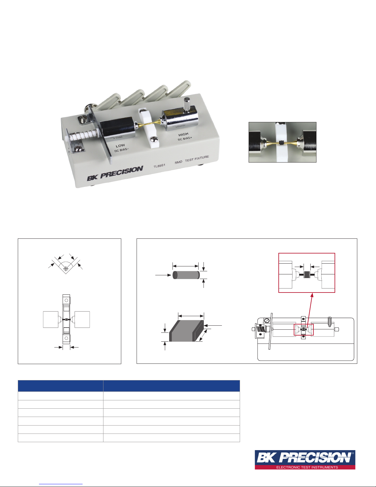
Component insertion site (closeup)
Test fixture for measuring small surface-mount devices (SMD)
The TL89S1 fixture is designed to probe SMD components with repeatable and accurate impedance measurements. The contactors are easily adjusted to
accommodate different sized components while applying the appropriate contact pressure. This test fixture is attached directly to the front panel of LCR models
889B, 891, 894, and 895.
Contactor pin
0.77 mm
0.77 mm
side view
7.0 mm
Component insertion site
Note: All mechanical measurements are typical
Specification TL89S1
Frequency DC to 10 MHz
DC Bias ±40 V peak max (AC+DC)
Operating Temperature 0 ºC to 40 ºC
Terminal Connection BNC, 4 terminal-pair
Dimensions (W x H x D) 5.125 x 2.37 x 3.31 inches (130 x 60.3 x 84 mm)
Weight: 0.67 lbs (0.305 kg)
Electrode
3.0 mm
8.1 mm
Cylindrical type
8.1 mm
Rectangular type
Component sizes
3.0 mm
Electrode
9.5 mm
0.2 mm ~ 8.1 mm
HIGHLOW
Technical data subject to change
© B&K Precision Corp. 2017
www.bkprecision.com
Page 2
SMD Test Fixture
TL89S1
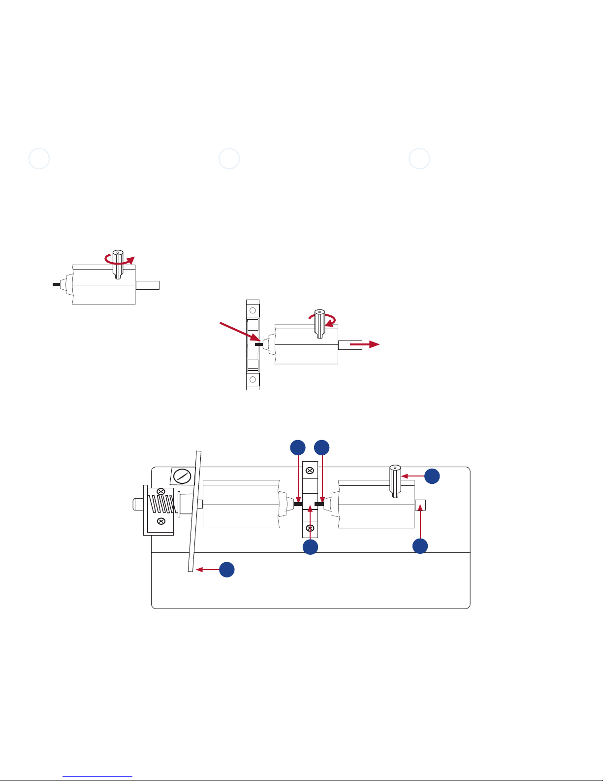
Adjusting the contactor pins
I
Loosen the lock screw (1) by turning the screw
counter clockwise 2 full turns.
Counter clockwise
(loosen)
HIGH
II III
Press the High contactor (2) to start the
extraction, grip the Contactor rod (4) on the
opposite side and pull the contactor open to
create a gap large enough to loosely fit the new
component. If more space is required, push the
Insertion lever (6) to the left until the component
fits into the Component insertion site (5).
clockwise (tighten)
HIGH
Gently press in on contactor rod (4) until the new
component is centered in component insertion
site (5).
Continue to apply pressure to the contactor rod
(4) while tightening the lock screw by turning it
clockwise. Do not over tighten the lock screw.
This completes the adjustment process and
components of the same size can now be easily
changed.
Press the Insertion lever (6) to retract the Low
contactor pin. While holding the lever open,
remove the previous component and place the
next component in the insertion site (5). Slowly
release the lever to contact the new component
and begin the next measurement.
Note: The contactor pins should be cleaned
periodically to remove contamination.
1. Lock screw
2. High contactor pin
3. Low contactor pin
4. Contactor rod
5. Component insertion site
6. Insertion lever
23
1
LOW
5
HIGH
4
6
Test fixture illustration
2
v082917
www.bkprecision.com
 Loading...