


Safety Summary
The following safety precautions apply to both operating and maintenance personnel and must be followed during all
phases of operation, service, and repair of this instrument.
Before applying power to this instrument:
• Read and understand the safety and operational information in this manual.
• Apply all the listed safety precautions.
• Verify that the voltage selector at the line power cord input is set to the correct line voltage. Operating the instrument
at an incorrect line voltage will void the warranty.
• Make all connections to the instrument before applying power.
• Do not operate the instrument in ways not specied by this manual or by B&K Precision.
Failure to comply with these precautions or with warnings elsewhere in this manual violates the safety standards of design,
manufacture, and intended use of the instrument. B&K Precision assumes no liability for a customer’s failure to comply
with these requirements.
2
Category rating
The IEC 61010 standard denes safety category ratings that specify the amount of electrical energy available and the
voltage impulses that may occur on electrical conductors associated with these category ratings. The category rating is
a Roman numeral of I, II, III, or IV. This rating is also accompanied by a maximum voltage of the circuit to be tested,
which denes the voltage impulses expected and required insulation clearances. These categories are:
Category I (CAT I): Measurement instruments whose measurement inputs are not intended to be connected to the
mains supply. The voltages in the environment are typically derived from a limited-energy transformer or a battery.
Category II (CAT II): Measurement instruments whose measurement inputs are meant to be connected to the mains
supply at a standard wall outlet or similar sources. Example measurement environments are portable
tools and household appliances.
Category III (CAT III): Measurement instruments whose measurement inputs are meant to be connected to the mains
installation of a building. Examples are measurements inside a building’s circuit breaker panel
or the wiring of permanently-installed motors.
Category IV (CAT IV): Measurement instruments whose measurement inputs are meant to be connected to the primary
power entering a building or other outdoor wiring.
Do not use this instrument in an electrical environment with a higher category rating than what is specied in this manual
for this instrument.
You must ensure that each accessory you use with this instrument has a category rating equal to or higher than the
instrument’s category rating to maintain the instrument’s category rating. Failure to do so will lower the category rating
of the measuring system.
Electrical Power
This instrument is intended to be powered from a CATEGORY II mains power environment. The mains power should be
115 V RMS or 230 V RMS. Use only the power cord supplied with the instrument and ensure it is appropriate for your
country of use.
Ground the Instrument
To minimize shock hazard, the instrument chassis and cabinet must be connected to an electrical safety ground. This
instrument is grounded through the ground conductor of the supplied, three-conductor AC line power cable. The power
cable must be plugged into an approved three-conductor electrical outlet. The power jack and mating plug of the power
cable meet IEC safety standards.
Do not alter or defeat the ground connection. Without the safety ground connection, all accessible conductive parts
(including control knobs) may provide an electric shock. Failure to use a properly-grounded approved outlet and the
recommended three-conductor AC line power cable may result in injury or death.
3
Unless otherwise stated, a ground connection on the instrument’s front or rear panel is for a reference of potential only
and is not to be used as a safety ground. Do not operate in an explosive or ammable atmosphere.
Do not operate the instrument in the presence of ammable gases or vapors, fumes, or nely-divided particulates.
The instrument is designed to be used in oce-type indoor environments. Do not operate the instrument
• In the presence of noxious, corrosive, or ammable fumes, gases, vapors, chemicals, or nely-divided particulates.
• In relative humidity conditions outside the instrument’s specications.
• In environments where there is a danger of any liquid being spilled on the instrument or where any liquid can condense
on the instrument.
• In air temperatures exceeding the specied operating temperatures.
• In atmospheric pressures outside the specied altitude limits or where the surrounding gas is not air.
• In environments with restricted cooling air ow, even if the air temperatures are within specications.
• In direct sunlight.
This instrument is intended to be used in an indoor pollution degree 2 environment. The operating temperature range is
0∘C to 40∘C and 20% to 80% relative humidity, with no condensation allowed. Measurements made by this instrument
may be outside specications if the instrument is used in non-oce-type environments. Such environments may include
rapid temperature or humidity changes, sunlight, vibration and/or mechanical shocks, acoustic noise, electrical noise,
strong electric elds, or strong magnetic elds.

Do not operate instrument if damaged
If the instrument is damaged, appears to be damaged, or if any liquid, chemical, or other material gets on or inside the
instrument, remove the instrument’s power cord, remove the instrument from service, label it as not to be operated,
and return the instrument to B&K Precision for repair. Notify B&K Precision of the nature of any contamination of the
instrument.
Clean the instrument only as instructed
Do not clean the instrument, its switches, or its terminals with contact cleaners, abrasives, lubricants, solvents, acids/bases,
or other such chemicals. Clean the instrument only with a clean dry lint-free cloth or as instructed in this manual. Not
for critical applications
This instrument is not authorized for use in contact with the human body or for use as a component in a life-support
device or system.
4
Do not touch live circuits
Instrument covers must not be removed by operating personnel. Component replacement and internal adjustments must
be made by qualied service-trained maintenance personnel who are aware of the hazards involved when the instrument’s
covers and shields are removed. Under certain conditions, even with the power cord removed, dangerous voltages may
exist when the covers are removed. To avoid injuries, always disconnect the power cord from the instrument, disconnect
all other connections (for example, test leads, computer interface cables, etc.), discharge all circuits, and verify there
are no hazardous voltages present on any conductors by measurements with a properly-operating voltage-sensing device
before touching any internal parts. Verify the voltage-sensing device is working properly before and after making the
measurements by testing with known-operating voltage sources and test for both DC and AC voltages. Do not attempt
any service or adjustment unless another person capable of rendering rst aid and resuscitation is present.
Do not insert any object into an instrument’s ventilation openings or other openings.
Hazardous voltages may be present in unexpected locations in circuitry being tested when a fault condition in the circuit
exists.
Fuse replacement must be done by qualied service-trained maintenance personnel who are aware of the instrument’s fuse
requirements and safe replacement procedures. Disconnect the instrument from the power line before replacing fuses.
Replace fuses only with new fuses of the fuse types, voltage ratings, and current ratings specied in this manual or on
the back of the instrument. Failure to do so may damage the instrument, lead to a safety hazard, or cause a re. Failure
to use the specied fuses will void the warranty.
Servicing
Do not substitute parts that are not approved by B&K Precision or modify this instrument. Return the instrument to
B&K Precision for service and repair to ensure that safety and performance features are maintained.
For continued safe use of the instrument
• Do not place heavy objects on the instrument.
• Do not obstruct cooling air ow to the instrument.
• Do not place a hot soldering iron on the instrument.
• Do not pull the instrument with the power cord, connected probe, or connected test lead.
• Do not move the instrument when a probe is connected to a circuit being tested.
Compliance Statements
Disposal of Old Electrical & Electronic Equipment (Applicable in the European Union and other European
countries with separate collection systems)
This product is subject to Directive 2002/96/EC of the European Parliament
and the Council of the European Union on waste electrical and electronic equipment
(WEEE), and in jurisdictions adopting that Directive, is marked as being put on the
market after August 13, 2005, and should not be disposed of as unsorted municipal
waste. Please utilize your local WEEE collection facilities in the disposition of this
product and otherwise observe all applicable requirements.
5

CE Declaration of Conformity
This instrument meets the requirements of 2006/95/EC Low Voltage Directive and 2004/108/EC Electromagnetic Compatibility Directive with the following standards.
Low Voltage Directive
– UL 61010-1:2012
EMC Directive
– EN 55011:2009+A2:2010
– EN 61000-3-11: 2000
– EN 61000-3-12: 2011
– EN 61000-4-2 / -3 / -4 / -5 / -6 / -8 / -34
– EN 61326-1: 2013
6
– EN 61326-2-1: 2013
Declaration of Conformity and test report available under request
Safety Symbols
Symbol Description
indicates a hazardous situation which, if not avoided, will result in death or serious injury.
indicates a hazardous situation which, if not avoided, could result in death or serious injury
indicates a hazardous situation which, if not avoided, will result in minor or moderate injury
Refer to the text near the symbol.
Electric Shock hazard
Alternating current (AC)
Chassis ground
Earth ground
This is the In position of the power switch when instrument is ON.
This is the Out position of the power switch when instrument is OFF.
is used to address practices not related to physical injury.

Contents
1 Introduction 9
1.1 Product Overview 9
1.2 Contents 9
1.3 Features 9
1.4 Dimensions 10
1.5 Front Panel 10
1.6 Display 11
1.7 Rear Panel 11
2 Getting Started 12
2.1 Input Power and Fuse Requirements 12
2.2 Fuse Replacement 14
2.3 Rackmount Installation 14
2.4 Output Connections 15
2.5 Preliminary Check 15
2.5.1 Verify AC Input Voltage 15
2.5.2 Connect Power 15
2.5.3 Warm-Up Time 15
2.5.4 Output Check 15
3 Front Panel Operation 18
3.1 Menu Options 18
3.1.1 Conguration 18
3.1.2 Parallel 18
3.1.3 PV Simulation 18
3.1.4 Power-On State 19
3.1.5 COMMUNICATION 19
3.1.6 System 19
3.2 How to Access the Menu 19
3.3 Congure Voltage/Current Output 20
3.3.1 Setting Voltage 20
3.3.2 Setting Current 20
3.3.3 Local Sense 21
3.4 Voltage/Current Measurement 22
3.5 Cong Menu 23
3.5.1 Output Limit Settings 23
3.5.2 Over Voltage Protection (OVP) 23
3.5.3 Over Current Protection (OCP) 24
3.5.4 Over Power Protection (OPP) 25
3.5.5 CV to CC Protection 25
3.5.6 CC to CV Protection 26
3.5.7 External Analog Control 26
3.5.8 External Control Settings 28
3.6 Local/Analog Control 28
3.7 Voltage Program 29
3.7.1 Voltage Mode 29
3.7.1 Resistor Mode 30
3.7.1 Voltage Monitor 31
3.7.2 Current Monitor 31
3.7.3 Shut O Control 31

4 Parallel Operation 32
4.1 Connection and Setup 32
4.2 Slave Unit 33
4.3 Master Unit 33
5 PV Simulation 35
6 Power- On State 37
7 Communication Conguration 38
7.1 USB 38
7.1.1 USBVCP 38
7.1.2 USBTMC 39
7.2 RS232 39
7.3 GPIB 40
7.4 RS485 41
7.5 LAN (Ethernet) 43
7.5.1 Web Server 45
7.6 Error/Event List 50
8 System Menu 51
8.1 Enable/Disable Key Sound 51
8.2 Error Log 51
8.3 Restore Factory Default Settings 52
8.4 Save/Recall Instrument Settings 54
8.4.1 Save Settings 54
8.4.2 Recall Settings 54
8.5 Program Function 55
8.5.1 Repeat and Next 55
8.5.2 Setup a Program 56
8.6 Timer 57
8.7 Slew Rate 58
8
9 Calibration 59
9.1 Voltage Calibration 60
9.2 Current Calibration 61
9.3 OVP Calibration 62
9.4 OCP Calibration 63
9.5 External Voltage Programming Calibration 64
9.6 External Current Programming Calibration 65
9.7 CC Calibration of External Voltage 66
9.8 CC Calibration of External Current 67
10 Specications 68
11 Service Information 70
12 LIMITED THREE-YEAR WARRANTY 71

Introduction
1.1 Product Overview
Figure 1.1 MR25080: 250 V / 80 A / 5000 W
B&K Precision models MR3K160120, MR160120, MR25080, MR50040, and MR100020 are high voltage programmable
DC power supplies with single outputs that oer the maximum power output up to 5000 watts. By connecting up
to *50 power supplies in parallel, a maximum output power can reach up to 250 kW. These power supplies are fully
programmable and controllable through analog programming, USB, RS232, RS485, GPIB and Ethernet interface. The
front numerical keypad and rotary knob provide a convenient interface for adjusting voltage, current, operating functions
and enabling/disabling the output. The MR series power supplies also provide over voltage protection (OVP) and
over current protection (OCP) features used to keep the output voltage and current within a specied safety level and
preventing damage to the UUT (Unit Under Test).
Model MR3K160120 MR160120 MR25080 MR50040 MR100020
Output Voltage 0 to 160 V 0 to 250 V 0 to 500 V 0 to 1000 V
Output Current 0 to 120 A 0 to 80 A 0 to 40 A 0 to 20 A
Output Power 3000 W 5000 W
Table 1.1 Models
1.2 Contents
Please inspect the instrument mechanically and electrically upon receiving it. Unpack all items from the shipping carton,
and check for any obvious signs of physical damage that may have occurred during transportation. Report any damage
to the shipping agent immediately. Save the original packing carton for possible future reshipment. Every power supply
is shipped with the following contents:
• 1 x MR3K160120, MR160120, MR25080, MR50040, or MR100020 Power Supply
• 1 x AC Power Cord
• 1 x Certicate of Calibration
• 1 x Test Report
Note:
Ensure the presence of all the items above. Contact the distributor or B&K Precision if anything is
missing.
1.3 Features

Introduction 10
• High power output of up to 5000 watts (0-160V/120A) (0-250V/80A) (0-500V/40A) (0-1000V/20A)
• USBVCP(virtual COM)/USBTMC/RS232/RS485/Analog/GPIB and Ethernet interfaces
• Parallel connectivity for up to *50 units
• Adjustable voltage and current slope
• 9 user dened programs with up to 100 steps each
• OVP, OCP, OPP, CV to CC, and CC to CV protection
• Store/recall up to 100 sets of voltage/current settings
*Parallel connectivity and operations can be congured in several dierent modes, however speed and performance will
decrease as each additional units are paralleled together. Refer to section 3.6 Parallel Operation and 4.1 RS485 for more
details regarding the conguration, setup, and limitations. If you wish to connect more than 10 units in parallel, we
advise to contact us at bkprecision.com for further assistance.
1.4 Dimensions
The MRs power supply’s dimensions are approximately:
16.5” x 3.5” x 21” (420 x 88 x 532 mm)
38.6 lbs (17.5 kg)
Figure 1.2 Dimensions
1.5 Front Panel
The front panel interface allows for control of the unit.
Item Description
1 Power Switch
Vacuum Fluorescent
2
3 LAN Status indicator
4 Keypad lock indicator
5 Main function keys
6 Numeric keys
7 Function keys
8 Rotary Knob
9 Navigation Keys
Display

Introduction 11
1.6 Display
Figure 1.3 Display
Item Description
1 Measured voltage
2 Settings voltage and current
3 Measured power output
4 Measured current
OFF Indicates output is disabled
CC Indicates constant current (CC) operation
CV Indicates constant voltage (CV) operation
RMT Indicates remote mode
Addr Indicates remote communication activity
Error Indicates an error has occurred
Shift Indicates shift mode (access to secondary button functions)
1.7 Rear Panel
Item Description
10 Output
11 USB Interface
12 RS-485 Interface
13
14 Ethernet (LAN) Interface
15 GPIB Interface
16 Earth ground connection
17 Remote sense terminals
18
19
Analog Programming
Interface(DB25 Connector)
RS-232 interface
& fuse box
AC input receptacle
& fuse box

Getting Started
Before connecting and powering up the instrument, please review and go through the instructions in this chapter.
2.1 Input Power and Fuse Requirements
The supply has a universal AC input that accepts line voltage input within:
Model MR3K160120 MR160120 MR25080 MR50040 MR100020
AC Line Input 200 to 240 VAC ± 10%, 47 Hz to 63 Hz
AC Line Phase Single phase
Maximum Rated
Input Power
Before connecting to an AC outlet or external power source, be sure that the power switch is in the OFF position and
verify that the AC power cord, including the extension line, is compatible with the rated voltage/current and that there
is sucient circuit capacity for the power supply. Once veried, connect the cable rmly.
4000 VA 6000 VA
Table 2.1 Input Power and Fuse Requirements
The included AC power cord is safety certied for this instrument operating in rated range. To change a cable or add
an extension cable, be sure that it can meet the required power ratings for this instrument. Any misuse with wrong
or unsafe cables will void the warranty.
SHOCK HAZARD:
The power cord provides a chassis ground through a third conductor. Verify that your power outlet is of the threeconductor type with the correct pin connected to earth ground.
Follow the instructions below to connect the AC power cable to the AC input of the power supply in the rear panel.
1. First, connect the input receptacle (green terminal block) of the cable to the input terminals of the power supply.
2. Align the power cord housing mounting holes on the left and right side to the screw holes on the power supply.
3. Use only the included screws to fasten and secure the cable housing assembly.

Getting Started 13
Figure 2.1 AC Power Connection Diagram
Refer to the descriptions below to connect the other end of the AC power cord to the AC distribution panel.
Do NOT plug the AC power cord into the wall socket prior to connecting ALL three AC power wires to the rear
panel and securely mount the safety metal housing over the input receptacle. Doing so may create a shock hazard.
Connection of this power supply to an AC power source should be made by a qualied electrician or other qualied
personnel. Incorrect wiring may damage the power supply or cause a re hazard
Connect the three terminals black to line1 (L1), white to line2 (L2) or neutral (N), and green to ground (G) on the
other end of the power cord to your AC distribution panel.
Figure 2.2 AC Power Cord
Getting Started 14
Safety agency requirements dictate that there must be a way to physically disconnect the AC mains
cable from the unit. A disconnect device, either a switch or circuit breaker must be meet the input
rating requirements at 30A in 200 Vac. The disconnect device provided in the nal installation must
be close to the instrument, must be easily accessible, and must be marked as the disconnect device
for this instrument.
2.2 Fuse Replacement
This power supply does not require a fuse that is user replaceable. There is an internal fuse, in which if blown, may
indicate a malfunction in the unit. In this event, contact B&K Precision.
A disassembling of the case or changing the fuse not performed by an authorized service technician will void the warranty
of the instrument.
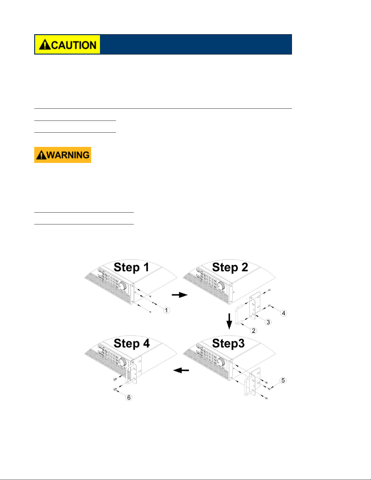
2.3 Rackmount Installation
The MR series power supplies are designed to t in a space of two rack units (2U) and can be mounted in a standard
19-inch rack panel or cabinet. Rack mount brackets must be assembled before mounting the unit in a rack. Refer to the
following gure to assemble the rack mount brackets.
Figure 2.3 Rack Mount Bracket Assembly

Getting Started 15
2.4 Output Connections
The main DC output terminal is a screw type terminal block located in the rear panel. Due to the high current rating of
the power supply, proper wire sizes are necessary for safe connectivity and to prevent wires from overheating. Refer to
the below table as a reference for proper wire sizes according to the amount of current used for operation:
Before connecting wires to the output terminals, turnOFF the power supply to avoid damage to the instrument and
the device under test (DUT). For safety, load wires must have a wire gauge size large enough to prevent overheating
when the power supply operates at maximum short circuit output current. It will also prevent large voltage drops from
resistances in the wires.
Hazardous voltages may exist at the outputs and the load connections when using a power supply with a rated output
greater than 40V. To protect personnel against accidental contact with hazardous voltages, ensure that the load and
its connections have no accessible live parts. Ensure that the load wiring insulation rating is greater than to the
maximum output voltage of the power supply.
2.5 Preliminary Check
Complete the following steps to verify that the power supply is ready for use.
2.5.1 Verify AC Input Voltage
Verify and check to make sure proper AC voltages are available to power the instrument. The AC voltage range must
meet the acceptable specication as explained in “2.1 Input Power and Fuse Requirements”.
2.5.2 Connect Power
Connect AC power cord to the AC receptacle in the rear panel and press the power switch to the (ON) position to turn
ON the instrument. On power up, the unit will display its model, shown in the screen below, and then check for the
optional modules.
Figure 2.4 Power On Display
2.5.3 Warm-Up Time
The MR series is fully operable upon switching the power ON. However, to reach the specied equipment accuracy, please
allow the supply to warm up for at least 15 minutes.
2.5.4 Output Check
Follow the steps below to check voltage output with no load connected.

Getting Started 16
1. Voltage Check
– Turn ON the power supply. The display will show the OFF annunciator above the voltage display.
– Enable the output by pressing . After pressing the button the LED next to the button will be lit. The OFF
annunciator will change to CV.
– Using the numeric keypad or the voltage adjust knob and enter a voltage value. The voltage display will now show
the value you entered. If entering with numeric keypad, press rst, then enter the value and press .
– (Optional) You may also verify the output voltage by connecting the (+) and (-) terminals on the rear panel to
an external voltmeter. The measured value should match or be within the entered voltage value.
Follow the steps below to check current output of the power supply.
2. Current Check
– Turn ON the power supply. The display will show the OFF annunciator above the voltage display. Be sure that the
output is disabled (the LED next to the button should not be lit when it is o). If the LED is ON, press
to disable output. Short the (+) and (-) output terminals with test leads, shorting bar, or clip. (Refer to
“– Wire Gauge Rating” to select appropriate test leads)
– Using the numeric keypad or the current adjust knob, enter a small current value (i.e. 1.000 A). If entering with
numeric keypad, press rst, then enter the value and press . The current display will now show the
value you entered.
– Enable the output by pressing , and the LED next to the button will be lit. The OFF annunciator will
change to CC.
– (Optional) You may also verify the output current by connecting either the (+) and (-) terminals on the rear panel
to an external current meter capable of measuring the current that you set. The measured value should match or
be within the entered current value.
– Press the power switch to the OFF position to turn o the power supply, then remove the short on the output
terminals.
3. Check Model and Firmware Version The model and rmware version can be veried by using the *IDN? query
remote command. It can also be found from within the menu system by following these steps:
– Press to enter the menu system.
– Press the button ve times until SYSTEM is select. Press . Press the button one time until
INFORMATION. Press , and the display will show the following screen:
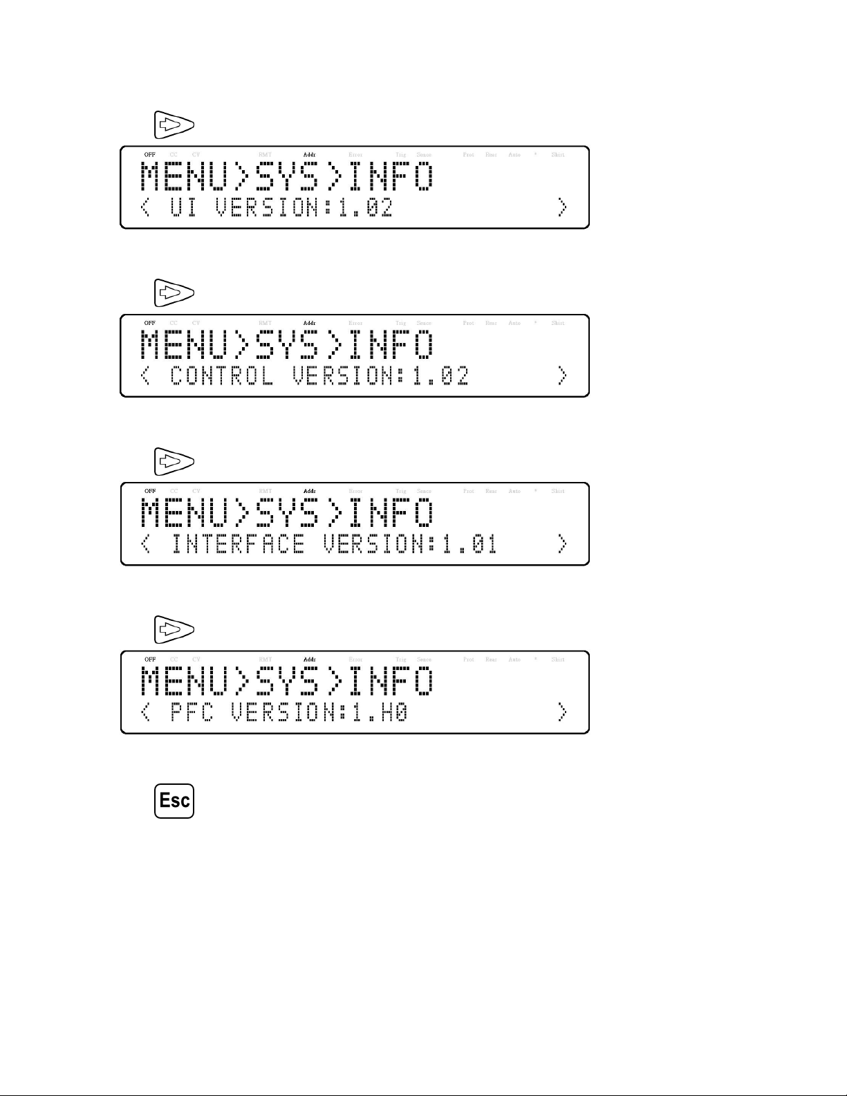
Getting Started 17
– The model is shown above as MR160120.
– Press twice again and the rmware version will displayed.
– The UI rmware is shown above as 1.02.
– Press once again and the rmware version will displayed.
– The control rmware is shown above as 1.02.
– Press once again and the rmware version will displayed.
– The interface rmware is shown above as 1.01.
– Press once again and the rmware version will displayed.
– The PFC rmware is shown above as 1.52.
– Press three times to exit the menu and return to the normal display.

Front Panel Operation
Figure 3.1 Menu Tree
3.1 Menu Options
All settings and parameters can be congured from the built-in menu system of the power supply. To access the menu,
press .
The menu system is divided into 5 sections and are organized as follows:
3.1.1 Conguration
Limit Congures voltage setting limits.
Protect Congures OVP, OCP, OPP, CV to CC, and CC to CV protection.
EXT Control Congures external analog control.
3.1.2 Parallel
Congures parallel connection and master/slave mode.
3.1.3 PV Simulation
Congures photovoltaic array simulator function.

Front Panel Operation 19
3.1.4 Power-On State
Congure power-on state.
3.1.5 COMMUNICATION
USB TMC/VCOM
GPIB
LAN
RS485
RS232
3.1.6 System
Beep Enable/Disable key sound.
Information Shows model, rmware version, communications settings, optional modules install and other power
supply information.
Calibration Calibration menu.
Default Select memory location for save/recall instrument settings.
3.2 How to Access the Menu
Before using the instrument, it is important to be familiarized with its menu structure and learn how to view or change
settings and parameters. Follow the steps below to guide you in selecting menu options.
1. From the normal display, press the button to enter the menu.
2. The selected item will be show. Use the keys to move through the menu selections.
3. When the desired menu section is show, press to access its menu settings. Below is the display when
CONFIGURATION is selected.
4. The selected item will be show. Use the keys to move through the menu items. When there is a on the
right side of the display, there are more menu items available to select from. Similarly, a will appear on the left
side of the display when there are menu items to the left. Use the keys accordingly to select the desired menu
item.
5. Press to access the selected menu item.

Front Panel Operation 20
6. There may be parameters or options to select within each menu item. Follow the same instructions as described in
the previous steps to select them. To save changes to a setting, press .
7. To exit the menu at any time, press until the normal.
3.3 Congure Voltage/Current Output
Voltage and current can be set from the front panel. Remote sense is also available on the rear panel for voltage
compensation at the output.
3.3.1 Setting Voltage
Follow the steps below to set the output voltage:
1. From the normal front panel display, users can use either the voltage adjust knob or the numeric keypad to enter the
setting voltage.
2. If entering using numeric keypad, press rst so that the cursor selects the voltage display. Then, enter the
value and press to set the voltage.
3. To change the cursor position use the keys. The voltage can be adjusted with the rotary knob.
When output is ON, the user can use the rotary to adjust the voltage value when the output is in constant voltage (CV)
mode. The output value will change simultaneously with the adjusted value. This is so called on-the-y function that
allows user to easily change the output value if the test is needed.
3.3.2 Setting Current
1. From the normal front panel display, users can use either the current adjust knob or the numeric keypad to enter the
setting current.
2. If entering using numeric keypad, press to select the current parameter. Then, enter the value and press
to set the current.
3. To change the cursor position use the keys. The current can be adjusted with the rotary knob.
When output is ON, the user can use the rotary to adjust the current value when the output is in constant current (CC)
mode. The output value will change simultaneously with the adjusted value. This is so called on-the-y function that
allows user to easily change the output value if the test is needed.

Front Panel Operation 21
3.3.3 Local Sense
By default, the power supply is set up for local sense. See the gure 3.2 for the Remote and Local Sense setup.
Figure 3.2 Local Sense
When local sense is selected, the positive lead (+) of the DC output is connected to the positive end (+) of the load
and the negative lead (-) of the DC output is connected to the negative end (-) of the load.
When this sensing mode is selected the wires connecting between DC outputs to the load must be as short as possible.
The local sense is the default conguration.
DO NOT disconnect the wires if remote sense is not used. Doing so will cause erratic behavior and may
damage the power supply under certain conditions.
Never connect any power source into any of the four terminals at any time during operation. When output
is enabled, DO NOT use your hands to touch the terminals or the screws that are designed to tighten wires
to the terminals. Doing so may create a shock hazard under high voltage output conditions.
Remote Sense
When remote sense is selected, the positive sense (+S) and positive lead (+) of the DC output are connected to the
positive end (+) of the load, whereas negative sense (-S) and negative lead (-) of the DC output are connected to the
negative end (-) of the load. To enable remote sense, follow the steps below:
1. Power OFF the supply and disconnect all loads and cables connected to it.
2. Use a small at blade screwdriver connect the S+ to the DUT’s positive (+) terminal, and connect the S- to the
DUT’s negative (-) terminal.
3. Do not connect any wires to Vo+ and Vo- terminals.
4. Power ON the power supply, and then congure and enable the output. The setup should look like the gure above.

Front Panel Operation 22
DO NOT at any time disconnect the wires from the Vs+ and Vs- terminals to the DUT while output is
enabled (ON). Doing so may damage the power supply and cause unstable output.
3.4 Voltage/Current Measurement
The display will show the set voltage and current values and the measured values of the output.
System Messages
The MR has built-in sensors to detect system conditions. If a fault status occurred, the error message will show on
the display and automatically protect the power supply output. The following display occurs when the fan has failed or
stopped turning:
System Message Description
MEMORY CHECK ERROR ! Cannot read or write the internal non- volatile memory
OVER TEMPURATURE PROTECT ! Internal temperature is too high and the protection mechanism is activated
FAN ERROR ! FAN not functioning
HW Fail OVP Module hardware over voltage
HW Fail OCP Module hardware over current
CALIBRATION ERROR ! Calibration cannot be done
AC FREQUENCY ABNORMAL ! AC input frequency is out of range
AC VOLTAGE ABNORMAL ! AC input voltage is out of range
PFC ERROR ! PFC not functioning correctly
POWER OFF ! Power supply is powering o
OUTPUT SHORT CIRCUIT Output voltage drop too fast
HW Fail BVbus Module hardware fail
 Loading...