

Page 1
Data Sheet
Modular Programmable DC Electronic Load
MDL Series
Features and Benefits
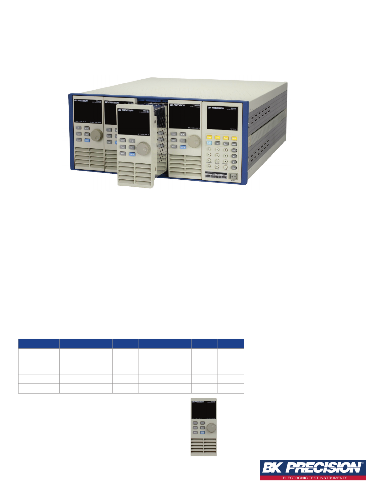
The MDL Series is a multi-channel modular
programmable electronic load system. Seven
mode, which uses DSP technology to simulate
non-linear loads and realistic loading behavior.
different modules of programmable DC loads
ranging in power from 200 W to 600 W
provide users the flexibility to test a wide range
of power sources from multi-output AC/DC
power supplies to batteries, fuel cells, and
photovoltaic arrays.
Easily edit the load’s parameters such as voltage,
current, slew rate, and width via the front panel.
Increase productivity by saving your test
parameters into any one of the 101 memory
areas for quick system recall. Additionally, the
MDL Series provides 16-bit resolution as well
The mainframe has four slots that can be
configured with any assortment of the modules
up to 2400 W (up to 4800 W with mainframe
as numerous protection modes and a power-on
system self-test to ensure the reliability of your
testing.
extension). The high-performance electronic load
modules of the MDL Series are capable of
operating in constant current (CC), constant
voltage (CV), constant resistance (CR), constant
power (CW), and constant impedance (CZ)
For remote communication, the MDL series
provides LAN, USBTMC compliant USB,
RS232, and GPIB standard interfaces that
support SCPI command protocol.
Modules MDL200 MDL252 MDL302 MDL305 MDL400 MDL505 MDL600
Power 200 W
*250 W/
50 W
300 W/
300 W
300 W 400 W 500 W 600 W
Operating Voltage 80 V 80 V 80 V 500 V 80 V 500 V 80 V
Rated Current 40 A 20 A 45 A 20 A 60 A 30 A 120 A
No. of Channels 1 2 2 1 1 1 1
* The MDL252 is a dual-channel 250 W load module supporting a
unique flexible power configuration. The user can allocate up to
250 W to either channel up to 300 W total (e.g. 50 W/250 W,
250 W/50 W, 150 W/150 W), thus replacing many dual-channel
modules with fixed power distribution.
■ Power range up to 2400 W
■ Voltage range up to 500 V
■ Current range up to 120 A
■ CC/CV/CR/CW/CZ operating modes
■ Removable modules for easy system
configurability
■ Support for up to 16 channels using dual
channel modules with mainframe extension
■ Operate identical modules in parallel mode
for high current applications
■ Synchronous Load on/off function
■ Standard LAN, GPIB, USB, and RS-232
interfaces with USBTMC/SCPI protocol support
■ Analog current control and monitoring
■ Transient mode up to 25 kHz
■ List mode (sequence mode) - minimum 20 µs
step width with 84 user programmable steps
■ Adjustable slew rate in CC mode
■ 16-bit voltage and current measurement
system providing high resolution of 0.1 mV
and 0.01 mA
■ Automatic test function
■ 101 memory locations to save/recall setting
parameters
■ Remote sense
■ OVP/OCP/OPP/OTP and reverse voltage
protection
Technical data subject to change
© B&K Precision Corp. 2015
www.bkprecision.com
Page 2
Modular Programmable DC Electronic Load
MDL Series
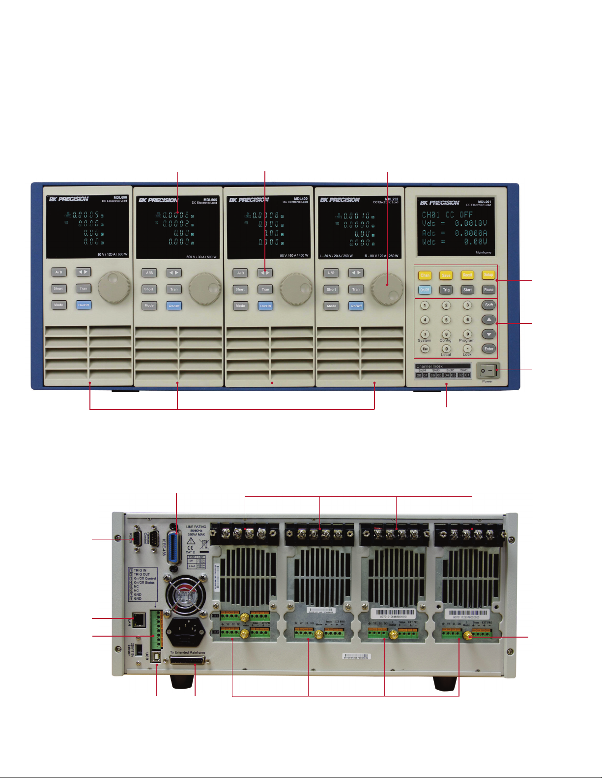
Front panel
▲
Brig h t VFD displa y
Modu le s
Ad j ust ment knobMo d u l e pan e l k ey s
Ma i n f r a m e
fu n c t i o n k eys
Num e r i c
ke ypad
Po w er
sw i tc h
Mai nfr a m e
Rear panel
▲
RS - 2 3 2 i n t e r f a ce
LAN i n terface
Mai n f r a m e
tri g ge r I/O and
sy nc h r onizati on
on /of f cont ro l
GP IB inte rfa c e
US B i nte rf a c e
Mai nfr a m e
ex te n s i o n
con nec t o r
Loa d inp u t termi nals
Modu le
current
mon i t o r i n g
term i n a l
Mo d u l e re m o t e s en s e , di g i t al I / O, a nd a n a log c u r r e nt c o n trol termina l
2 www.bkprecision.com
Page 3

Modular Programmable DC Electronic Load
MDL Series
The tools you need
High p e r formance a rch i t e c ture
Equipped with a high-performance microprocessor
in every mainframe and module, the MDL Series
rogrammable DC electronic load utilizes a
p
parallel architecture that provides a high
measurement speed. Additionally, a simultaneous
load on/off operation can be performed through
he front panel, analog control terminal, or remote
t
SCPI command. This configuration allows the
system to control modules synchronously and
increases productivity in testing.
Modular d esign
With removable module design, you can choose
suitable load modules to modify the system
ccording to your requirements. This design
a
allows for multiple channels and is ideal for
testing several units, especially power supplies
with multiple outputs. At the same time, all load
odules can be configured to work independently.
m
All load modules, including the high power 500
W and 600 W modules can fit in one slot. Unlike
competitor models that require two slots for high
power modules, the MDL Series offers a one-slot
form factor for all modules.
Po w e rful c o m m u ni cation interfaces
The MDL Series mainframe offers all the latest
options to the user for remote communication.
Connect via GPIB, Ethernet, USB, or RS232 to
carry out data communication through SCPI and
USBTMC standard communication protocols to
control all your electronic load modules from a
PC.
Ad j ustable s l ew r a t e
In constant current mode, users can control the
rate or slope of the change in current in a
transient response test. Set the slew rate to as
slow as 0.0001 A/
µs or as fast as 2.5 A/µs
depending on the module and selected current
range.
Low Vo l t ag e O p e r a tion
The MDL series can operate at low voltages for applications such as fuel cell and solar cell testing.
Tra n s i e n t opera t i o n
Transient operation enables the module to
periodically switch between two load levels.
power supply’s regulation and transient
A
characteristic can be evaluated by monitoring
the supply’s output voltage under varying
combinations of load levels, duty cycle, and slew
ate. The MDL Series can simulate these
r
conditions up to 25 kHz.
A
High Level
Low Level
Slew Rate
T
List m o d e
Not limited to just switching between two levels,
list mode lets you generate more complex
sequences of input changes with several different
levels. Up to 7 groups of list files can be saved
in the mainframe. Each list can contain up to 84
steps with a minimum width time of 20
µs per
step.
Typical minimum operating voltage at full scale current:
MDL200 MDL252 MDL302 MDL305 MDL400 MDL505 MDL600
1 V 1 V 1.4 V 4.5 V 1.5 V 5.4 V 1.8 V
A
T
Au t om atic t e s t mo d e
The MDL Series can execute multiple test
sequences across all channels. Sequences can be
cascaded, and each step can be programmed
with upper and lower limit values. When applied
in automatic production testing, you can easily
judge whether the test parameters of your
devices are within the specification limits and
adjust your process according to the GO/NG
verdict.
3 www.bkprecision.com
Page 4

Modular Programmable DC Electronic Load
MDL Series
Specifications
Model MDL200 MDL252 MDL302 MDL305 MDL400 MDL505 MDL600
nput ratings
I
Input Voltage 0-80 V 0-80 V 0-80 V 0-500 V 0-80 V 0-500 V 0-80 V
Input Current
Input Power 200 W 250 W / 50 W
Channels 1 2 2 1 1 1 1
Minimum
Operating
Voltage
V mode
C
Range
Resolution
Accuracy
CC mode
Range
Resolution
Accuracy
CR mode
Range
Resolution 16-bit
Accuracy
CW mode
Resolution 10 mW
Accuracy ± (0.2 % + 0.2 % F.S.)
Transient mode (CC mode)
T1&T2
Accuracy 5 µs+100 ppm
Slew Rate
1)
MDL252: The user can allocate up to 250 W to either channel up to 300 W total (e.g. 50 W/250 W, 250 W/50 W, 150 W/150 W).
2)
Fast pulse trains with large transitions may not be achievable.
3)
The slew rate specifications are not warranted, but are descriptions of typical performance. The actual transition time is defined as the time for the input to change from 10% to 90%, or vice versa, of the
programmed current values. In case of very large load changes, e.g. from no load to full load, the actual transition time will be larger than the expected time. The load will automatically adjust the slew rate to fit
within the range (high or low) that is closest to the programmed value.
Low 0-4 A 0-3 A 0-4.5 A 0-3 A 0-6 A 0-3 A 0-12 A
High 0-40 A 0-20 A 0-45 A 0-20 A 0-60 A 0-30 A 0-120 A
1
300 W / 300 W 300 W 400 W 500 W 600 W
Low 0.10 V at 4 A 0.15 V at 3 A 0.14 V at 4.5 A 0.7 V at 3 A 0.15 V at 6 A 0.54 V at 3 A 0.18 V at 12 A
High 1 V at 40 A 1 V at 20 A 1.4 V at 45 A 4.5 V at 20 A 1.5 V at 60 A 5.4 V at 30 A 1.8 V at 120 A
Low 0-18 V
High 0-80 V 0-80 V 0-80 V 0-500 V 0-80 V 0-500 V 0-80 V
Low 1 mV
High 10 mV
Low ± (0.05 % + 0.02 % F.S.) ± (0.05 % + 0.025 % F.S.) ± (0.05 % + 0.02 % F.S.)
High ± (0.05 % + 0.025 % F.S.)
Low 0-4 A 0-3 A 0-4.5 A 0-3 A 0-6 A 0-3 A 0-12 A
High 0-40 A 0-20 A 0-45 A 0-20 A 0-60 A 0-30 A 0-120 A
Low 0.1 mA 1 mA 0.1 mA
High 1 mA 10 mA 1 mA
Low ± (0.05 % + 0.05 % F.S.) ± (0.05 % + 0.1 % F.S.)
High ± (0.05 % + 0.05 % F.S.) ± (0.1 % + 0.1 % F.S.)
Low 0.05 Ω-10 Ω 0.05 Ω-10 Ω 0.05 Ω-10 Ω 0.25 Ω-10 Ω 0.05 Ω-10 Ω 0.2 Ω-10 Ω 0.2 Ω-10 Ω
High 10 Ω-7.5 kΩ
Low 0.01 % + 0.08
High 0.01 % + 0.0008
S
S
Range 200 W 250 W 300 W 300 W 400 W 500 W 600 W
2
Low 0.0001-0.25 A/µs 0.0001-0.2 A/µs 0.0001-0.25 A/µs 0.0001-0.1 A/µs 0.0001-0.25 A/µs 0.0001-0.1 A/µs 0.0001-0.25 A /µs
3
20 us-3600 s / Res: 5 µs-10 ms
High 0.001-2.5 A/µs 0.001-2 A/µs 0.001-2.5 A/µs 0.001-1 A/µs 0.001-2.5 A/µs 0.001-1 A/µs 0.001-2.5 A/µs
4 www.bkprecision.com
Page 5

Modular Programmable DC Electronic Load
MDL Series
Specifications
Model MDL200 MDL252 MDL302 MDL305 MDL400 MDL505 MDL600
eadback voltage
R
Range
Resolution
Accuracy ± (0.025 % + 0.025 % F.S.)
Readback current
Range
Resolution
Accuracy
Readback power
Range 200 W 250 W 300 W 300 W 400 W 500 W 600 W
Resolution 10 mW
Accuracy ± (0.2 % + 0.2 % F.S.)
Protection range (typical)
OPP 200 W 250 W 310 W 300 W 400 W 500 W 600 W
OCP
OVP 82 V 82 V 82 V 510 V 82 V 510 V 82 V
OTP 185 ºF (85 ºC)
General (typical)
Short Circuit
Current (CC)
Voltage (CV) 0 V
Resistance (CR) 25 mΩ 50 mΩ 30 mΩ 220 mΩ 25 mΩ 180 mΩ 15 mΩ
Input Terminal Impedance 300 kΩ 300 kΩ 300 kΩ 1 MΩ 300 kΩ 1 MΩ 300 kΩ
Safety EN61010-1:2001, EU Low Voltage Directive 2006/95/EC
Electromagnetic Compatibility
Dimensions 3.2” x 7.2” x 22.6” (82 x 183 x 573 mm)
Weight 11 lbs (5 kg)
Low 0-18 V
High 0-80 V 0-80 V 0-80 V 0-500 V 0-80 V 0-500 V 0-80 V
Low 0.1 mV 0.1 mV 0.1 mV 1 mV 0.1 mV 1 mV 0.1 mV
High 1 mV 1 mV 1 mV 10 mV 1 mV 10 mV 1 mV
Low 0-4 A 0-3 A 0-4.5 A 0-3 A 0-6 A 0-3 A 0-12 A
High 0-40 A 0-20 A 0-45 A 0-20 A 0-60 A 0-30 A 0-120 A
Low 0.01 mA 0.01 mA 0.01 mA 0.01 mA 0.1 mA 0.01 mA 0.1 mA
High 0.1 mA 0.1 mA 0.1 mA 0.1 mA 1 mA 0.1 mA 1 mA
Low ± (0.05 % + 0.05 % F.S.) ± (0.05 % + 0.1 % F.S.)
High ± (0.05 % + 0.05 % F.S.) ± (0.1 % + 0.1 % F.S.)
Low 4.4 A 3.3 A 5 A 3.3 A 6.6 A 3.3 A 13.2 A
High 44 A 22 A 50 A 22 A 66 A 33 A 132 A
Low 4 A 3 A 5 A 3 A 6 A 3 A 12 A
High 40 A 30 A 50 A 20 A 60 A 30 A 120 A
Meets EMC Directive 2004/108/EC, EN 61000-3-2:2006, EN 61000-3-3:1995+A1:2001+A2:2005
EN 61000-4-2/-3/-4/-5/-6/-11, EN 61326-1:2006
Three-Year Warranty
5 www.bkprecision.com
Page 6

Modular Programmable DC Electronic Load
MDL Series
Mainframe Specification
Number of
Slots
4 110/220 V ±10%, 50/60 Hz
Note: Applies to MDL001 mainframe and MDL002 mainframe extension.
Power Input
Operating
Temperature
32 to 104 ºF
(0 to 40 °C)
Storage
Temperature
14 to 140 ºF
(-10 to 60 °C)
Mechanical Specifications
Model Type Dimensions (W x H x D) Weight
MDL001 Mainframe
MDL002
MDL200 Module
MDL252 Module
MDL302 Module
MDL305 Module
Mainframe
Extension
17.5” x 7.2” x 21.6”
(445 x 183 x 549 mm)
17.5” x 7.2” x 21.6”
(445 x 183 x 549 mm)
3.2” x 7.2” x 22.6”
(82 x 183 x 573 mm)
3.2” x 7.2” x 22.6”
(82 x 183 x 573 mm)
3.2” x 7.2” x 22.6”
(82 x 183 x 573 mm)
3.2” x 7.2” x 22.6”
(82 x 183 x 573 mm)
Humidity
Indoor use, ≤95%
34 lbs (15.4 kg)
34 lbs (15.4 kg)
11 lbs (5 kg)
11 lbs (5 kg)
11 lbs (5 kg)
11 lbs (5 kg)
MDL400 Module
MDL505 Module
MDL600 Module
3.2” x 7.2” x 22.6”
(82 x 183 x 573 mm)
3.2” x 7.2” x 22.6”
(82 x 183 x 573 mm)
3.2” x 7.2” x 22.6”
(82 x 183 x 573 mm)
Standard Accessories
Mainframes
Modules
Power cord, user manual, mainframe extension cable (MDL002 only)
Certificate of calibration and test report
Optional Accessories
Rack mount kit IT-E153A for mainframes MDL001 and MDL002.
11 lbs (5 kg)
11 lbs (5 kg)
11 lbs (5 kg)
6 www.bkprecision.com
v022516
 Loading...