

Page 1

Page 2

Safety Summary
The following safety precautions apply to both operating and maintenance personnel and must be followed during all
phases of operation, service, and repair of this instrument.
Before applying power to this instrument:
• Read and understand the safety and operational information in this manual.
• Apply all the listed safety precautions.
• Verify that the voltage selector at the line power cord input is set to the correct line voltage. Operating the instrument
at an incorrect line voltage will void the warranty.
• Make all connections to the instrument before applying power.
• Do not operate the instrument in ways not specied by this manual or by B&K Precision.
Failure to comply with these precautions or with warnings elsewhere in this manual violates the safety standards of design,
manufacture, and intended use of the instrument. B&K Precision assumes no liability for a customer’s failure to comply
with these requirements.
Category rating
The IEC 61010 standard denes safety category ratings that specify the amount of electrical energy available and the
voltage impulses that may occur on electrical conductors associated with these category ratings. The category rating is
a Roman numeral of I, II, III, or IV. This rating is also accompanied by a maximum voltage of the circuit to be tested,
which denes the voltage impulses expected and required insulation clearances. These categories are:
Category I (CAT I): Measurement instruments whose measurement inputs are not intended to be connected
to the mains supply. The voltages in the environment are typically derived from a limitedenergy transformer or a battery.
Category II (CAT II): Measurement instruments whose measurement inputs are meant to be connected to
the mains supply at a standard wall outlet or similar sources. Example measurement
environments are portable tools and household appliances.
Category III (CAT III): Measurement instruments whose measurement inputs are meant to be connected to
the mains installation of a building. Examples are measurements inside a building’s circuit breaker panel or the wiring of permanently-installed motors.
Category IV (CAT IV): Measurement instruments whose measurement inputs are meant to be connected to
the primary power entering a building or other outdoor wiring.
Do not use this instrument in an electrical environment with a higher category rating than what is specied in this manual
for this instrument.
You must ensure that each accessory you use with this instrument has a category rating equal to or higher than the
instrument’s category rating to maintain the instrument’s category rating. Failure to do so will lower the category rating
of the measuring system.
1
Page 3

Electrical Power
This instrument is intended to be powered from a CATEGORY II mains power environment. The mains power should be
115 V RMS or 230 V RMS. Use only the power cord supplied with the instrument and ensure it is appropriate for your
country of use.
Ground the Instrument
To minimize shock hazard, the instrument chassis and cabinet must be connected to an electrical safety ground. This
instrument is grounded through the ground conductor of the supplied, three-conductor AC line power cable. The power
cable must be plugged into an approved three-conductor electrical outlet. The power jack and mating plug of the power
cable meet IEC safety standards.
Do not alter or defeat the ground connection. Without the safety ground connection, all accessible conductive parts
(including control knobs) may provide an electric shock. Failure to use a properly-grounded approved outlet and the
recommended three-conductor AC line power cable may result in injury or death.
Unless otherwise stated, a ground connection on the instrument’s front or rear panel is for a reference of potential only
and is not to be used as a safety ground. Do not operate in an explosive or ammable atmosphere.
Do not operate the instrument in the presence of ammable gases or vapors, fumes, or nely-divided particulates.
The instrument is designed to be used in oce-type indoor environments. Do not operate the instrument
• In the presence of noxious, corrosive, or ammable fumes, gases, vapors, chemicals, or nely-divided particulates.
• In relative humidity conditions outside the instrument’s specications.
• In environments where there is a danger of any liquid being spilled on the instrument or where any liquid can condense
on the instrument.
• In air temperatures exceeding the specied operating temperatures.
• In atmospheric pressures outside the specied altitude limits or where the surrounding gas is not air.
• In environments with restricted cooling air ow, even if the air temperatures are within specications.
• In direct sunlight.
This instrument is intended to be used in an indoor pollution degree 2 environment. The operating temperature range is
0∘C to 40∘C and 20% to 80% relative humidity, with no condensation allowed. Measurements made by this instrument
may be outside specications if the instrument is used in non-oce-type environments. Such environments may include
rapid temperature or humidity changes, sunlight, vibration and/or mechanical shocks, acoustic noise, electrical noise,
strong electric elds, or strong magnetic elds.
2
Page 4

Do not operate instrument if damaged
If the instrument is damaged, appears to be damaged, or if any liquid, chemical, or other material gets on or inside the
instrument, remove the instrument’s power cord, remove the instrument from service, label it as not to be operated,
and return the instrument to B&K Precision for repair. Notify B&K Precision of the nature of any contamination of the
instrument.
Clean the instrument only as instructed
Do not clean the instrument, its switches, or its terminals with contact cleaners, abrasives, lubricants, solvents, acids/bases,
or other such chemicals. Clean the instrument only with a clean dry lint-free cloth or as instructed in this manual. Not
for critical applications
This instrument is not authorized for use in contact with the human body or for use as a component in a life-support
device or system.
Do not touch live circuits
Instrument covers must not be removed by operating personnel. Component replacement and internal adjustments must
be made by qualied service-trained maintenance personnel who are aware of the hazards involved when the instrument’s
covers and shields are removed. Under certain conditions, even with the power cord removed, dangerous voltages may
exist when the covers are removed. To avoid injuries, always disconnect the power cord from the instrument, disconnect
all other connections (for example, test leads, computer interface cables, etc.), discharge all circuits, and verify there
are no hazardous voltages present on any conductors by measurements with a properly-operating voltage-sensing device
before touching any internal parts. Verify the voltage-sensing device is working properly before and after making the
measurements by testing with known-operating voltage sources and test for both DC and AC voltages. Do not attempt
any service or adjustment unless another person capable of rendering rst aid and resuscitation is present.
Do not insert any object into an instrument’s ventilation openings or other openings.
Hazardous voltages may be present in unexpected locations in circuitry being tested when a fault condition in the circuit
exists.
Fuse replacement must be done by qualied service-trained maintenance personnel who are aware of the instrument’s fuse
requirements and safe replacement procedures. Disconnect the instrument from the power line before replacing fuses.
Replace fuses only with new fuses of the fuse types, voltage ratings, and current ratings specied in this manual or on
the back of the instrument. Failure to do so may damage the instrument, lead to a safety hazard, or cause a re. Failure
to use the specied fuses will void the warranty.
Servicing
3
Page 5
Do not substitute parts that are not approved by B&K Precision or modify this instrument. Return the instrument to
B&K Precision for service and repair to ensure that safety and performance features are maintained.
For continued safe use of the instrument
• Do not place heavy objects on the instrument.
• Do not obstruct cooling air ow to the instrument.
• Do not place a hot soldering iron on the instrument.
• Do not pull the instrument with the power cord, connected probe, or connected test lead.
• Do not move the instrument when a probe is connected to a circuit being tested.
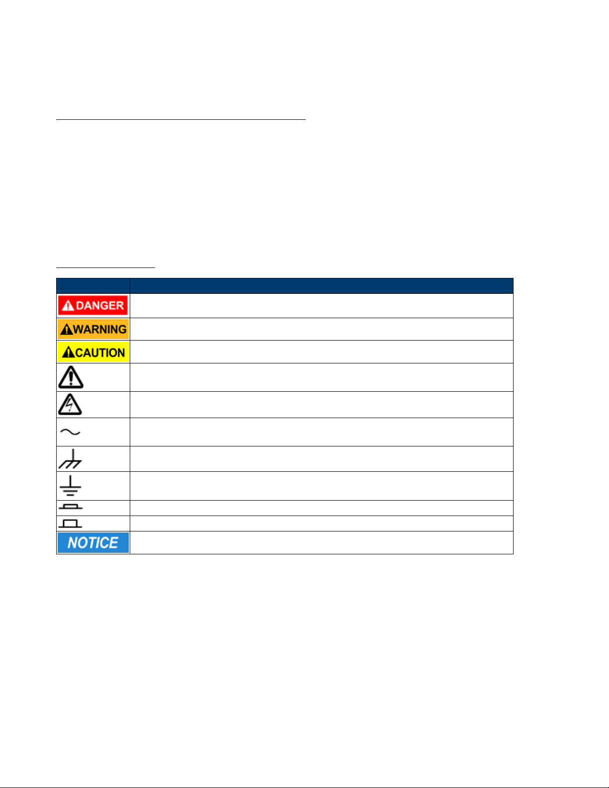
Safety Symbols
Symbol Description
indicates a hazardous situation which, if not avoided, will result in death or serious injury.
indicates a hazardous situation which, if not avoided, could result in death or serious injury
indicates a hazardous situation which, if not avoided, will result in minor or moderate injury
Refer to the text near the symbol.
Electric Shock hazard
Alternating current (AC)
Chassis ground
Earth ground
This is the In position of the power switch when instrument is ON.
This is the Out position of the power switch when instrument is OFF.
is used to address practices not related to physical injury.
2
Page 6

Contents
1 Introduction 6
1.1 Electrical Connections 6
1.2 DAS240-BAT Extension Module 6
1.3 Home screen 8
1.4 Recording Period 8
1.4.1 Example: Recording 9 Channels 9
1.4.2 Example: Power-Line, engine noise, or other electrical noise. 9
2 Setup 10
2.1 Switching On 10
2.1.1 Switching Off 10
2.1.2 In Case of Error 11
2.2 Extension Modules (DAS240-BAT only) 11
2.3 External Power 12
2.4 Battery 12
2.4.1 To Ensure Long Battery Life 12
2.4.2 To Charge the Battery 13
2.5 Calibration 13
2.5.1 Factory Default Calibration 13
2.6 Keypad Lock 14
2.7 System Setup 14
2.8 Language 14
2.9 Screen Shut Off (Dimming) 15
2.10 VNC 15
2.11 Additional Options 15
2.12 Firmware Update 15
2.13 Instrument Conguration Loading and Saving 15
2.14 Network 15
2.15 Alarms 16
3 Channel Setup 17
3.1 All Channels Screen 17
3.2 Individual Channel Screen 17
3.3 Extension Modules (DAS240-BAT only) 17
3.4 Measurement Connections 18
3.4.1 Voltage Measurement 18
3.4.2 Temperature Measurement With a Thermocouple 19
3.4.3 Temperature Measurement With Pt100/Pt1000 and RTD 19
3.4.4 Resistance Measurement 19
3.4.5 Current Measurement 20
4 F(t) Plot 22
4.1 Screen Setup 22
4.1.1 Custom Pages 23
4.2 Freeze Screen and Cursor Measurements 23
4.3 Time Base 24
4.4 Math 24
4.4.1 Math Functions 25
5 XY Plot 28
6 Numeric Display 30
3
Page 7

7 Recording 31
7.1 Create a Recording 31
7.2 View Recording 31
7.2.1 Loading a Recording 31
8 Triggering Recordings 34
8.1 Waiting Start Condition 34
8.2 Recordings 34
8.3 Triggering 35
8.3.1 Single Analog Channel Trigger 35
8.3.2 Single Threshold 36
8.3.3 Multiple Thresholds 37
8.3.4 Trigger Examples 38
8.4 Trigger on Logic Channels 38
9 Alarms 39
9.1 Alarm Status 39
9.2 Analog/Math/Timing Signal Alarm 40
9.3 Analog Signal Combination Alarm 40
9.4 Logic (Digital) Signal Alarm Trigger 41
9.5 Alarm on Recording Start (Trigger Acquisition) 42
10 Logic Channels 43
10.1 Logic Input Connector 43
10.2 Logic Channel Setup 43
10.3 Timing 44
10.4 Alarm Outputs 44
11 File Management 46
11.1 Note: 46
11.1 Setup Files 46
11.1.1 Default 47
11.1.2 Save Setup Files 47
11.1.3 Load Setup Files 47
11.2 Recordings Files 47
12 Remote Interfaces 48
12.1 LAN Interface 48
12.1.1 LAN Setup 48
12.2 VNC 48
12.2.1 Changing the Password 48
12.3 Network File Transfer 48
12.4 Viewing with SeframViewer 49
12.4.1 Example 50
12.5 Device Control with DASLab 50
12.6 Modbus (slave) 51
12.6.1 Setup Modbus Slave 51
12.6.2 Mapping Modbus TCP 52
12.6.2.1 Analog Data 52
12.6.2.2 Logical Data 52
13 Maintenance 53
13.1 Updating the Internal Software 53
14 Specications 54
4
Page 8

15 Thermocouple Measurement Accuracy 55
15.1 J Type Thermocouple Example 55
15.2 Measurement Accuracy: Pm 55
15.3 Voltage of Thermocouple (mV) 55
15.3.1 Example of Accuracy Calculation 56
15.4 Accuracy Class - Class Index 56
15.5 Grounding 57
16 LIMITED TWO-YEAR WARRANTY 58
17 Service Information 59
5
Page 9
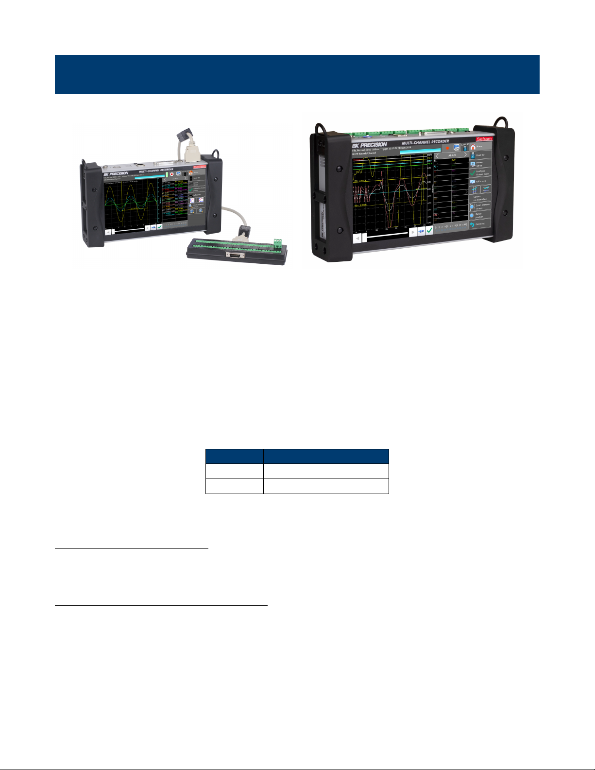
Introduction
DAS240-BAT DAS220-BAT
Figure 1.1 Front View
The DAS240-BAT and DAS220-BAT programmable recorders can measure measure voltage, current, temperature (thermocouple, Pt100, Pt1000), resistances, and logic channels. Highlights include:
• An intuitive interface on a wide capacitive and color 10” touchscreen
• 32GB internal memory for storing recordings
• Composed of a main base frame and extension modules of 20 channels each
• Programmable via Ethernet using NTP, FTP and VNC protocols
• Built-in battery with capacity to run the recorder for hours
Model Channels
DAS240-BAT 20-200 using expansion blocks
DAS220-BAT 10
Table 1.1 Channel Options
1.1 Electrical Connections
Connection to the recorders uses modular connectors shown in Figure 1.2 and Figure 1.3.
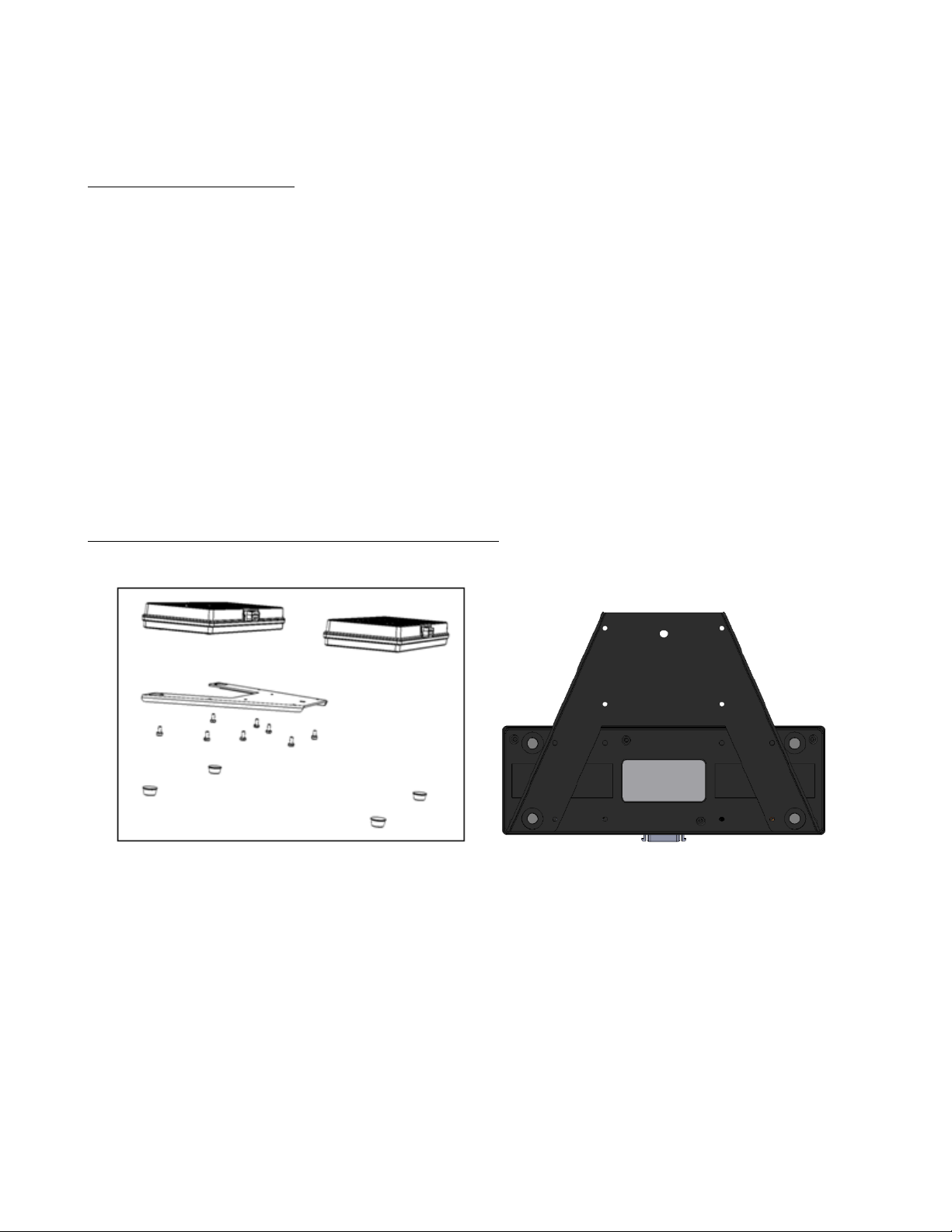
1.2 DAS240-BAT Extension Module
Signals are connected to the unit via terminal blocks, see Figure 1.4. These blocks accommodate 20 connections each
and may be chained together to provide more channels.
6
Page 10
Item Description
1 Power Connector
2 Charging LED
3 ON/OFF Switch
4 USB Connectors
5 LAN Interface
6 Logic and Alarm Signals
7 Ground
8 Expansion Module
Figure 1.2 DAS240-BAT Electrical Connections
Item Description
1 Channel Inputs
2 Power Connector
3 Charging LED
4 ON/OFF Switch
5 USB Connectors
6 LAN Interface
7 Logic and Alarm Signals
8 Ground
Figure 1.3 DAS220-BAT Electrical Connections
7
Page 11
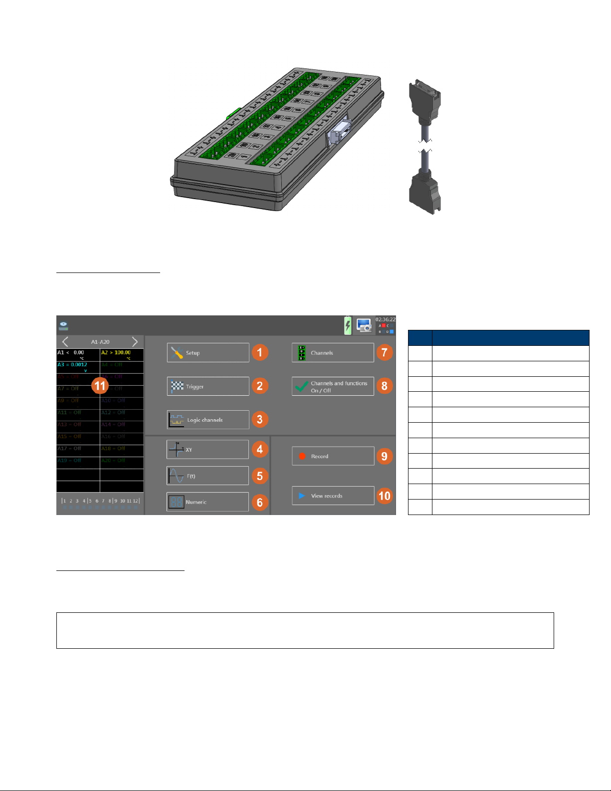
Figure 1.4 Terminal Block and Cable
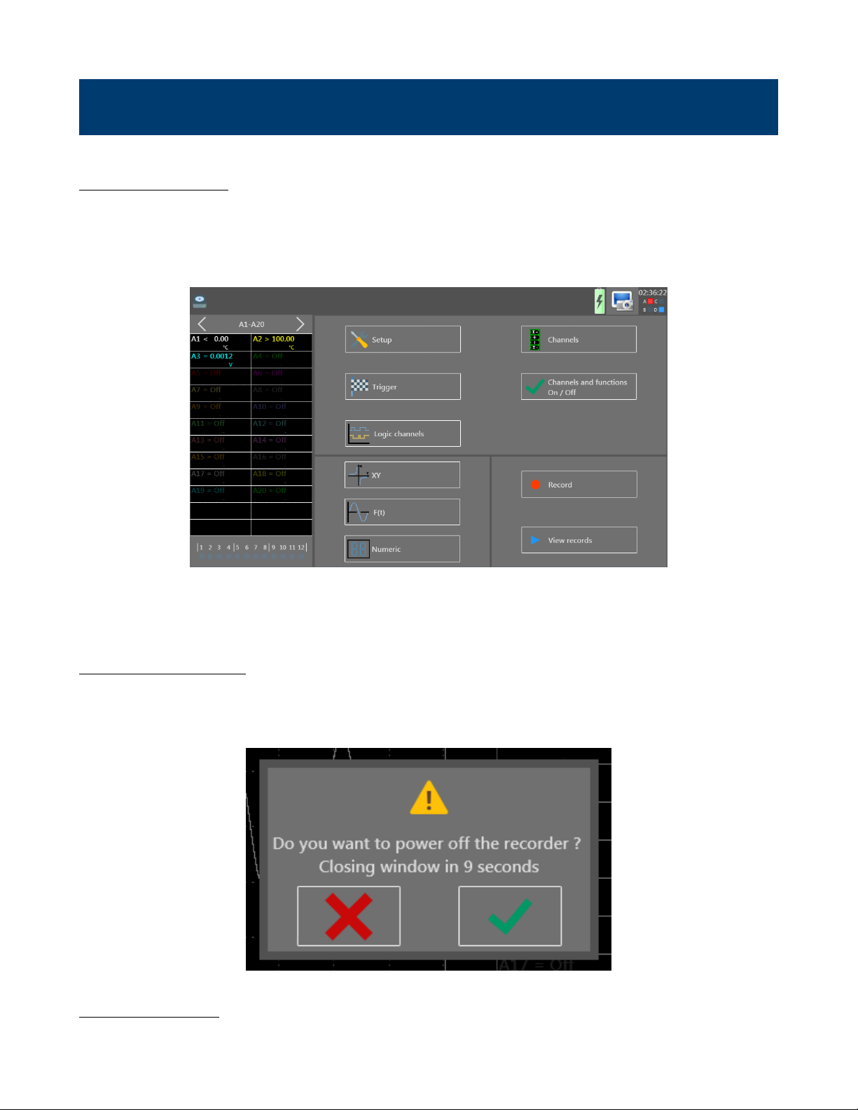
1.3 Home screen
The home screen provides access to the various functions and settings of the unit. Access this menu via the “Home”
button in the top right corner of the screen.
Item Description
1 Setup Menu
2 Trigger Menu
3 Logic Channel Cong Menu
4 XY Display
5 F(t) Display
6 Numeric Display
7 Channel Setup Menu
8 Channel and Function Display Cong
9 Recording Display
10 Recording Replay Screen
11 Channel Conguration Screen
Figure 1.5 Home Screen
1.4 Recording Period
The acquisition sample rate is congurable. The unit samples one channel at a time. The sample period denes the time
a sample consumes.
Note: Each channel is sampled in sequence. The effect is that the rate at which a channel is sampled depends on
the number of channels and the sample period of each channel. See Section 1.4.1
The sample period is set to one of the following settings: 1, 2, 5, 10, 20, 50 and 100ms. When 3-wire thermocouple
measurements (Pt100 and Pt1000) are made, the time periods are doubled. The doubled time periods are highlighted
in the channel setup dialog with a “(x2)” beside the period. Also, by using a congurable low-pass lter per channel,
measurements can be made ltering out higher frequency components.
8
Page 12

1.4.1 Example: Recording 9 Channels
For example, if 9 channels are sampled, and the settings for each channel sample period are [50, 50, 20, 20, 20, 20,
10, 10, 5] ms each, the total time for an acquisition is 200 ms. Consequently, the minimum recording period, the time
between samples of an individual channel, is 200 ms. See Figure 1.6.
50ms
Start
CH1
50ms
CH2
Total Time = 200 ms
Figure 1.6 9ch Ex.
20ms
CH3
20ms
CH4
20ms
CH5
20ms
Ch6
1.4.2 Example: Power-Line, engine noise, or other electrical noise.
For white noise or noise with lower frequency (lower than recording frequency), you can choose a software lter.
10ms
CH7
5ms
10ms
CH8
CH9
End
9
Page 13
Setup
2.1 Switching On
Prior to powering ON the unit, connect the extension modules1(DAS240-BAT).
Turn on the recorder by pressing the button at the top. When the recorder is on, the ON/OFF button will illuminate,
and displays a startup screen showing the hardware version. It then switches automatically to “F(t)” mode. This display
is accessible from the “Home” menu, Figure 2.1, by pressing the “F(t)” key.
Figure 2.1 Home Screen
On power-up, the unit recalls the last settings and congurations used.
2.1.1 Switching Off
To switch off the recorder, press the ON/OFF button. A dialog box appears prompting the user to conrm powering
off the unit. Select the green check mark to proceed. The dialog disappears if either the red “X” is pressed or the 10 s
countdown expires. Before the unit turns off, the setup will be saved and the current le will be closed.
Figure 2.2 On Off Dialog
1
If there are no modules connected or detected, the will display “Error:Ti” in the lower right-hand corner of the startup screen
10
Page 14
If the recorder does not switch off correctly, then press the ON/OFF button for 5 seconds. Congurations and setup
values may not be saved in this case. This is also true if the unit loses power.
2.1.2 In Case of Error
• If the unit still starts normally: reinitialize to default settings. From the main menu open the “Setup” menu, then
click on “Default setup” key. See Section 2.7.
• Alternatively, the unit can be reset to factory defaults.
− With the unit power off, press the power button to turn the unit on.
− While the unit is booting up, quickly and repeatedly press power button until the display shows a white startup
screen. A setup_error.cnf le will be created in the root folder of the internal memory.
− The unit resets to defaults and reverts to French.
− To change the language back to English, press “Menu Principal”, then “Conguration”, then press the French
ag and select the British ag for English.
Note: If errors persist, please contact B&K Precision for further assistance.
2.2 Extension Modules (DAS240-BAT only)
Up to 10 extension modules may be connected at a time.
Figure 2.3 Extension Modules
To assemble multiple terminal block modules:
• Screw the electrical connectors’ plate to each additional extension
• Assemble the extension modules together
• Screw the plates with the adjacent modules
• Stick the additional adhesive buttress
• Connect the cable using unlocking levers
• Connect the cable on the DAS240-BAT (must be powered off rst)
• Switch on the unit.
11
Page 15
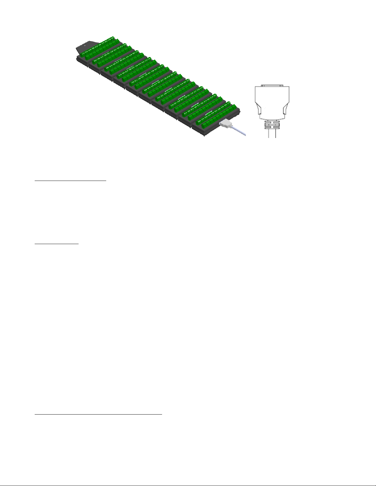
Figure 2.4 Breakout Cable and Module
Note: The unit is delivered with a 70 cm cable.
2.3 External Power
The DAS240-BAT and DAS220-BAT recorders are powered and charged using a 15V DC, 5A power supply.
Warning: To minimize the risk of shock, the instrument chassis and cabinet must be connected to an electrical safety
ground. This instrument is grounded through the ground conductor of the supplied, three-conductor AC line power cable.
The power cable must be plugged into a three-conductor electrical outlet.
Warning: When the charger is connected to the unit, the chassis is connected to the power supply earth ground.
2.4 Battery
The unit is equipped with a lithium-ion battery. If the unit has remained unused for more than one month, check its
charge status and recharge it if necessary.
For continued safe use:
• Never heat up or expose the battery pack to re
• Never short the battery: there is a risk of explosion!
• Do not puncture the battery.
• Do not dismantle the battery pack.
• Do not reverse the polarities of the battery.
• This battery pack includes protection that should not be damaged or removed.
• Do not store the pack in a place exposed to excessive heat.
• Do not damage the protective sheath of the pack.
• Do not store inside a vehicle exposed to the sun.
The battery should last at least 200 full charge-discharge cycles or 2 years.
2.4.1 To Ensure Long Battery Life
• Do not store for a long time without use.
• Store the battery at around 40% charge.
• Do not fully charge or discharge the battery before storage.
12
Page 16
When the battery is nearly discharged, the unit closes all open les, stops the software, and will shut off automatically.
2.4.2 To Charge the Battery
• Connect the provided external AC adapter to the power input of the unit.
• Connect the AC adapter to a electrical outlet.
• The green LED will light when the battery is charging and will turn off when charging is complete.
• Charging can be done with the unit turned on or off.
Note: Battery replacement and service should be performed by B&K Precision. Contact us for details.
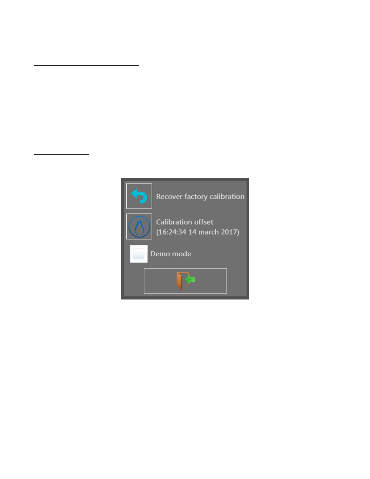
2.5 Calibration
The recorder inputs for the voltage and thermocouple offsets can be calibrated. This will remove any offset present on
different channels.
Figure 2.5 Offset Calibration Screen
1. Let the unit warm up for 20 minutes at ambient temperature 68-77F (20-25C).
2. Enter the recorder main page and then press the “Setup” key.
3. Select the “Additional Option” menu.
4. Select the “Electric Calibration” menu.
5. Press the “Calibration offset” to start calibration. This takes approximately 5 minutes.
6. Power cycle the unit.
2.5.1 Factory Default Calibration
The default factory calibration can be restored to correct any possible mistake in the calibration coecients. This restores
calibration values congured at the factory. This is performed as follows:
13
Page 17
1. Let the unit warm up for 20 minutes at ambient temperature 68-77F (20-25C).
2. Enter the recorder main page and then press the “Setup” key.
3. Select the “Additional Option” menu.
4. Select the “Electric Calibration” menu.
5. Press the “Recover factory calibration”.
6. Power cycle the unit.
2.6 Keypad Lock
To lock all keys:
• Press the “Setup” key.
• Press the “Additional Option” key.
• Press the “Locking the recorder” key.
• Press the green check mark to conrm and lock the unit.
The keypad lock will occur 10 seconds after conrmation.
A yellow padlock appears in the upper right corner of the display when locked. To unlock the recorder, press the lock
icon in the upper right corner repeatedly.
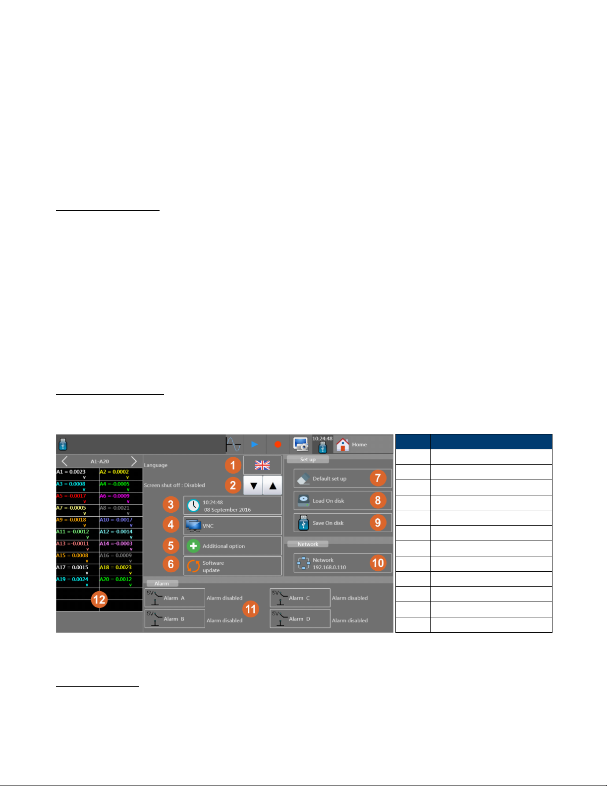
2.7 System Setup
The Setup Menu provides access to general setup of the instrument, monitoring of the alarm outputs, network address
TCP/IP, calibration of the channels, and software (rmware) updating. The setup menu is shown in Figure 2.6.
Button Description
1 Language
2 Screen dimming time
3 Date and time setup
4 VNC setup
5 Additional settings
6 Update
7 Load default settings
8 Load conguration from disk
9 Save conguration to disk
10 Network status and setup
11 Alarms
12 Channels
Figure 2.6 Setup Menu
2.8 Language
The system language can be set to one of the following: French, Spanish, English, Italian, German, and Swedish. Open
the language dialog by pressing the ag icon on the setup screen (Home>Setup). Then select the ag icon that correlates
to the language, Figure 2.7.
14
Page 18

Figure 2.7 System Languages
2.9 Screen Shut Off (Dimming)
The amount of time the screen back-light stays at full brightness may be set from 1-30 mins or (disabled). Use the arrow
keys to change the screen shut off timeout.
2.10 VNC
VNC (Virtual Network Computing) allows the user to mirror the front panel using a viewer on a networked computer.
This button is for setting the password. See Section 12.2 for more details.
2.11 Additional Options
Setting the screen brightness, locking the screen, calibrating the machine, setting the start-up screen image and settings
for the Modbus server are available in this menu. See Section 2.5 for calibration information, and see Section 2.6 for
screen lock information.
2.12 Firmware Update
See Chapter 13 for details about updating the rmware.
2.13 Instrument Conguration Loading and Saving
Settings like the F(t) time/division and channels to display may be saved and recalled by the instrument. Also, a default
set of settings may also be loaded. These can be congured with the 3 buttons in the “Setup” box of the setup display
window (home>setup).
2.14 Network
The current IP addresses of the network is shown within the network button. If there is no network connection, 0.0.0.0
is shown.
15
Page 19

Figure 2.8 Network
Conguration Dialog
Pressing the button opens the network conguration dialog. Available options are shown in this window depending on
the hardware connected. DHCP, IP Address, Subnet Mask, and Gateway IP can be congured here.
2.15 Alarms
See Chapter 9 for details.
16
Page 20
Channel Setup
3.1 All Channels Screen
Access the channel setup menu from the Home screen and press the “Channels” button. The screen shown in Figure 3.1
appears.
Figure 3.1 Channels Menu
The channel conguration screen provides quick access to individual channel settings. Each column lists a set of values
for each channel. The parameter available is listed in the left and right most columns. Pressing the box corresponding to
the channel and parameter opens a dialog box with options for conguring that parameter. The contents of the dialog
change depending on the selected parameter value. For example, when the channel type parameter is opened, selecting
the Thermocouple value modies the box to give further options for thermocouples (type, temperature units, etc…).
Back on the main channel table, the value in the box shows a summary version of the parameter’s congured value.
In the upper right and left corners of the table are navigation arrows for showing more sets of channels. 10 channels may
be shown on screen at a time.
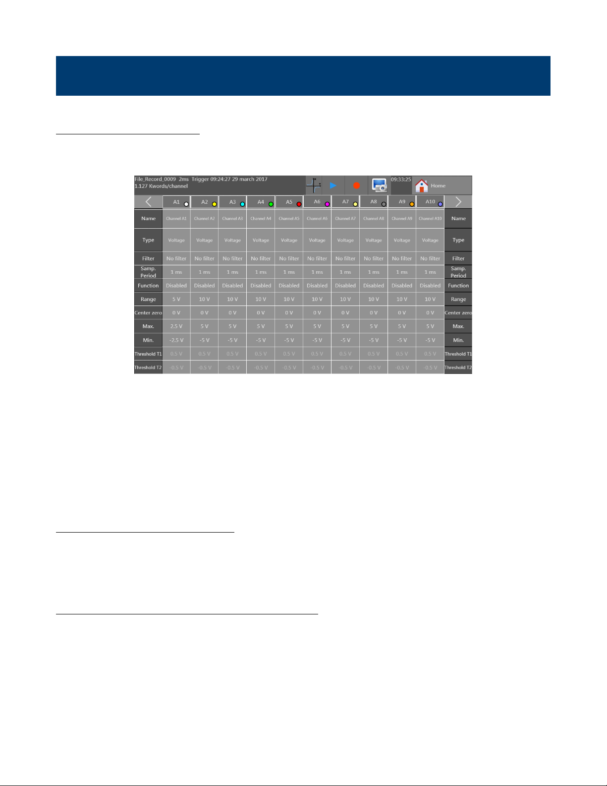
3.2 Individual Channel Screen
The complete set of parameters, values and options are also viewable for a single channel on a single screen. To open this
screen, press the box displaying the Channel ID (A1 for example). This opens a window for setting a greater number of
values than available from the channels table. For example, the plot color and thickness can be set here. See Figure 3.2.
3.3 Extension Modules (DAS240-BAT only)
Up to 10 extension modules may be connected at a time.
To assemble multiple terminal block modules:
• Screw the electrical connectors’ plate to each additional extension
• Assemble the extension modules together
• Screw the plates with the adjacent modules
• Stick the additional adhesive buttress
17
Page 21
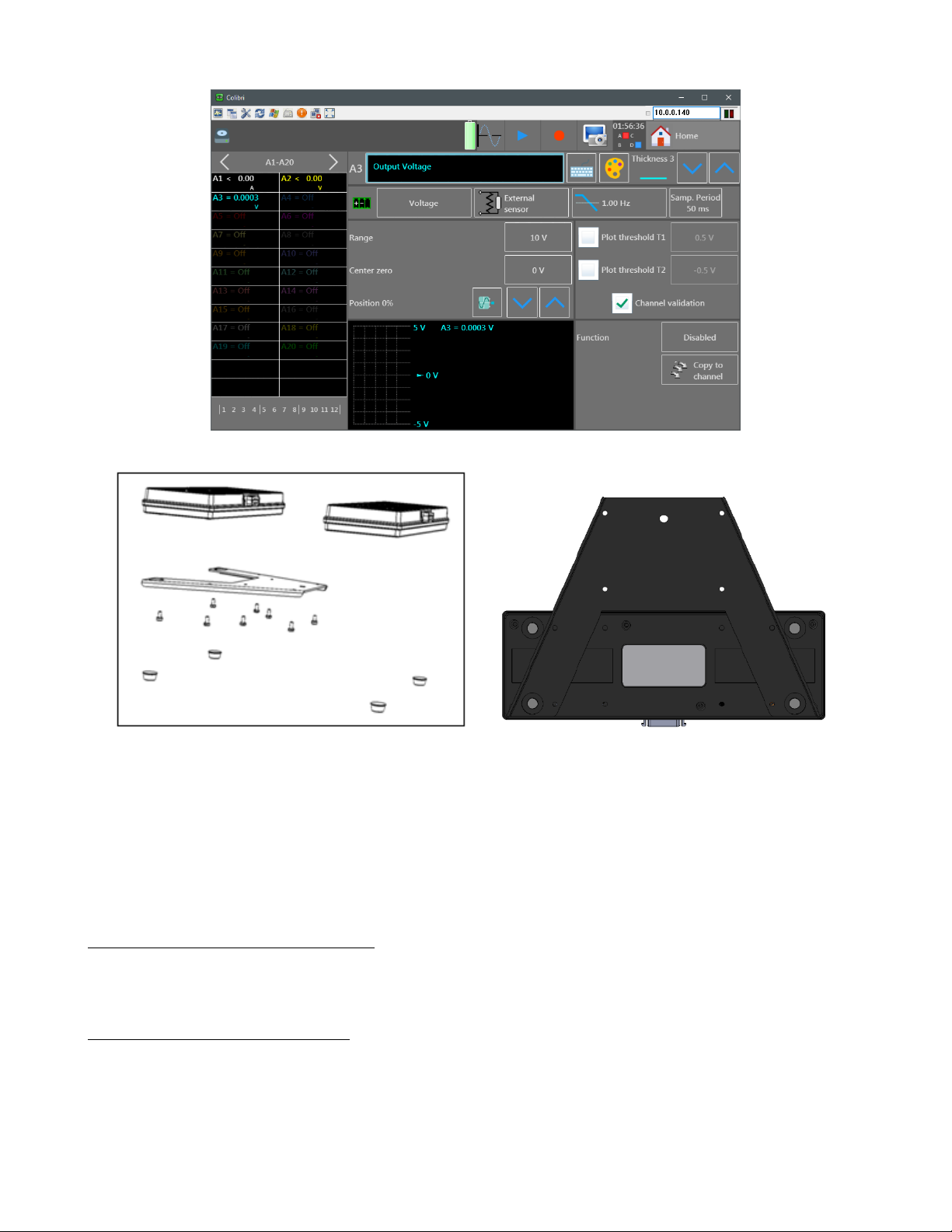
Figure 3.2 Channel Conguration Screen
Figure 3.3 Extension Modules
• Connect the cable using unlocking levers
• Connect the cable on the DAS240-BAT (must be powered off rst)
• Switch on the unit.
Note: The unit is delivered with a 70 cm cable.
3.4 Measurement Connections
Using the terminal blocks provided with the unit. Figure 3.5. (Phoenix Contacts: SMSTB 2,5/3-ST5,08 - 1826296)
3.4.1 Voltage Measurement
Voltage measurement is performed between the + and - terminals of the inputs. The “GND” terminal is not used.
18
Page 22

Figure 3.4 Breakout Cable and Module
Figure 3.5 Terminal Blocks
3.4.2 Temperature Measurement With a Thermocouple
The voltage resulting from thermocouple is measured between the + and - terminals of the relevant input. The “GND”
terminal is not used. Errors in reading temperature can be caused by reverse connection of the thermocouple wires.
3.4.3 Temperature Measurement With Pt100/Pt1000 and RTD
The Pt100/Pt1000 probe must be connected to the + and - terminals. The current injects into the “GND” terminal.
For a 4 wire Pt100/Pt1000, only 3 wires are used.
Note: the “gnd” current injection is shared by all channels.
Figure 3.6 shows 2 ways to wire the temperature sensors. Using the 2-wire method, the “-” and “GND” terminals are
connected together at the terminal block. For 3-wire, the ground connects at the measurement point.
2 Wire 3 Wire
Figure 3.6 Terminal
Block Wiring
3.4.4 Resistance Measurement
Connect the resistance to measure between the “+” and “-” terminals and connect the “-” and “GND” terminals together.
For best resolution and accuracy, congure the resistance display range appropriately for the expected value. For example,
19
Page 23

set the on screen range close to the expected measurement value. Based on the range chosen, the unit determines the
sense current and voltage range to use for measurement.
3.4.5 Current Measurement
The recorder includes the option to convert sensed voltage across a shunt or sense resistor into a current reading. From
the “Home” screen, open the “Channels” menu. The “Type” row shows the current function per channel. Press the
square in the “channel” column and “Type” row to open the conguration dialog for the function type. See gure 3.7.
Select the “Current” menu option. The window will change to show a button listing the current shunt value. To change
the value, press the button and a dialog for setting the shunt value will open. See Figure 3.8. Set the value and unit
and press the green check mark to conrm the setting and the screen will return to the previous menu.
To wire the circuit for current measurement, connect the “+” and “-” terminals to the current shunt. Also, set the
current range in the “Channels” window appropriately. Use either an external resistance or a shunt (ref 902406500: 50Ω
Figure 3.9).
Figure 3.7 Channel Function Type
20
Page 24

Figure 3.8 Current Shunt Value Setup
Figure 3.9 50Ω Shunt Module
21
Page 25

F(t) Plot
This mode displays the channel signals versus time, much like an oscilloscope. The time per division is called the
“Timebase” on this unit. The display is normally in a scrolling mode displaying real time data. This changes when
recording data. In that case, the display shows the full record. See Chapter 7 for more information about recording
data.
Item Description
1 Screen Setup, Section 4.1.
2 Congure custom pages,
Section 4.1.1
3 Freeze Screen, Section 4.2
4 Full Screen - change the view to
full screen, touch the screen
anywhere to exit.
5 Timebase, Section 4.3
6 Numerical display - display the
current signal value and control
which channel page is displayed.
7 F(t) plot
Figure 4.1 F(t) Screen
4.1 Screen Setup
Figure 4.2 Screen Setup Dialog
From this dialog, the type of plot, numerical values, math, grid scales, number of plots, and colors are set here. The
number of plots is available when in F(t) mode, and is limited to the number of signals measured. The maximum number
is 10. When in XY mode, the number of plots is replaced by the option to enable a custom grid (background image).
When a custom grid is enabled, the options of directory and le are added to the dialog as in Section 4.3. Lastly, the
choice of displaying points as dots or vectors is available for the XY display mode.
22
Page 26

Figure 4.3 Screen Setup Dialog - XY mode
4.1.1 Custom Pages
Using this menu, set the channels to see on screen from the available channels set using the “Channels and Functions
On/Off” menu. The channels are divided into banks and the shown bank is set here. For example, this allows channels
1 and 10 to be shown on the screen and turn off other channels.
4.2 Freeze Screen and Cursor Measurements
Freezes the graph at the screen to perform measurements through cursors, calculations, save or print the measurements
at screen, in the F(t) mode.
When frozen, horizontal and vertical cursor icons are added to the right-hand panel. Selecting the vertical cursor icon
enables time based cursors. Move the individual cursors by the touchscreen or other mouse interface to set the
cursor positions. selecting the horizontal cursor icon changes the available buttons in the right hand panel, See
Figure 4.4.
Icon Description
Undo the last cursor action completed.
Opens a dialog box for setting the signal to measure with the cursors.
Zoom the selected channel to t within the current cursor settings.
Set the vertical axis parameters for the selected channel.
The range is the vertical span of the channel.
The center value denes what value is the middle of the axis.
The “Position” denes the vertical location of the horizontal axis (time) in percentage.
The range is from -100 to 100 %.
For example, -50 will place the horizontal axis at 2.5 divisions above the bottom of the display.
All together, the range sets how many volts tall the vertical axis is, center sets the
23
Page 27
Figure 4.4 Horizontal
Cursor Options
Figure 4.5 Time Base Setting (Time/Division)
4.3 Time Base
The trace time scale may be set to a number of values. Pressing the Timebase button on the right of the F(t) plot screen
brings up the dialog as shown in Figure 4.5.
4.4 Math
Math functions may be applied to multiple channels. To enable math functions, enable the check-box for “Math” in the
“Screen Setup” window. When enabled, the icon is added to the right hand button panel. Pressing the
button brings up the conguration dialog shown in Figure 4.6. Use the arrow buttons at the top to increase of decrease
the number of math functions. Use the arrows at the bottom to change the channel on which the math is done, or press
the channel named for each row to set the desired channel. See Figure 4.7 for the set of functions available.
The values calculated for each function congured are shown on the main plot screen, colored the same as the channel
they do math on. See Section 4.4.1
Calculated values are displayed in the plot window showing the following:
24
Page 28

• channel number (with its color)
• function name
• value
Figure 4.6 F(t) Channel
Math Settings Dialog
Figure 4.7 F(t) Channel Math Functions Dialog
4.4.1 Math Functions
Math function values may be moved around on the screen. To move the math values, click and drag them to a desired
position on screen.
Minimum
Maximum
Peak to Peak
25
Page 29

Figure 4.8 Math Dialog Box
Low The most frequent value below the median
High The most frequent value above the median
Amplitude
On positive oscillation
On negative oscillation
Average frequency
Cycle average
Rising edge T1 = 10% Amplitude T2 = 90% Amplitude Trise = T2 - T1
𝑀𝑎𝑥−𝐻 𝑖𝑔ℎ
𝐴𝑚𝑝𝑙𝑖𝑡𝑢𝑑𝑒
𝐿𝑜𝑤−𝑀𝑖𝑛
𝐴𝑚𝑝𝑙𝑖𝑡𝑢𝑑𝑒
1
𝑃 𝑒𝑟𝑖𝑜𝑑
Duration of N complete periods
∗100
∗100
𝑁
culated on as many periods as possible
Average duration of a complete cycle cal-
26
Page 30

Falling edge T1 = 90% Amplitude T2 = 10% Amplitude Tfall = T2 - T1
Positive pulse width Measurement of the time of 1st positive pulse. It is measured at 50% of am-
plitude
Negative pulse width Measurement of the time of 1st negative pulse. It is measured at 50% of
amplitude
Positive duty cycle
Negative duty cycle
N : total number of dots
RMS
Standard Deviation
positive pulse duration
𝑝𝑒𝑟𝑖𝑜𝑑
negative pulse duration
𝑝𝑒𝑟𝑖𝑜𝑑
𝑁
1
∑
𝑉
- Note
𝑖
𝑁
𝑖=1
𝑁
√
√
1
𝑁
1
𝑁
∑
(𝑉𝑖)
𝑖=1
𝑁
∑
(𝑉𝑖−𝑉)
𝑖=1
2
- Note
2
2
2
- Note
2
2
Calculated using the whole graphic range
27
Page 31

XY Plot
The XY mode is accessible via the main menu by pressing the XY key. In this mode, one of the channel represents the
horizontal axis (X), and the other channel the vertical axis (Y). For example, if the channel for the horizontal axis is 1V
and the channel for the vertical axis is at 95F, the recorder plots a point at (1,95).
A custom background/grid may also be shown on the display. From the “Screen Setup” menu accessed by pressing the
button on the XY plot screen, select the “custom grid” check-box, select the folder containing the bitmap to be used
(middle button), and select the bitmap using the right most button on the line. Along with the XY plot, a numeric
representation of the current signal values is shown.
Item Description
1 Screen conguration - Open the
measurement display
2 Trace - Allows to start or stop
the trace
3 Delete Allows to delete the
screen
4 X channel Selects the channel
for the horizontal axis
5 Full screen Allows to view on the
full screen, press on the reticule
to come back to the normal
mode
6
Figure 5.1 XY Display Screen
Arrow key shows or hides
the numerical window
Item Description
1 Plot type - F(t) or XY
2 Point display - Dots or vectors
3 Display Numerical Values -
shows the numerical values in a
table
4 Display Boundaries - shows or
hides the axes
5 Custom Grid - congures the
grid and background image
6 Colors - sets the color of the
background, grid and cursor
using a color picker
Figure 5.2 XY Setup Window
28
Page 32

Figure 5.3 Numerical Window
1. The or keys : selects the group to view.
2. By pressing a specic channel:
− The graph terminals are bound to this channel.
− In real time acquisition, the instant value will show up.
− By visualizing the cursors; then the difference value between cursors as well as T1 and T2 values corresponding
to cursors T1 and T2 will be displayed.
3. Press right to hide this window, and when hidden, the icon points left.
29
Page 33
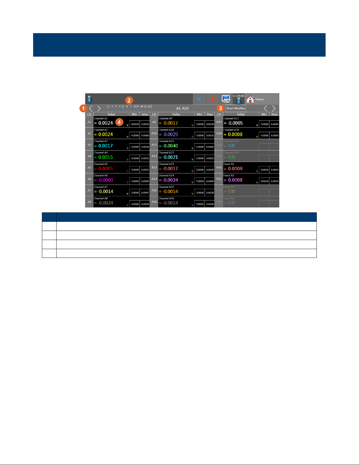
Numeric Display
The numerical window allows to visualize in real time the values of each channel. See Figure 6.1. The number of
channels shown per screen depends on the number of channels selected. Each display page is accessed by pressing the
right and left arrows.
Item Description
1 Cycle display screens (channels, custom sets, logic functions, etc…)
2 Digital channel state (shown when “Logic Channels” option is set in the “Channels and Functions” menu.
3 Reset minimum and maximum recorded values
4 Individual channels, click within each channel to open the conguration menu for that channel
Figure 6.1 Numeric Display Screen
30
Page 34

Recording
The DAS240-BAT and DAS220-BAT can save data to internal storage. The user can then retrieve the data and review
it on the unit, save it to a USB drive, or retrieve it via the Ethernet interface.
7.1 Create a Recording
To create recordings, press the “record” button on either the “setup” screen or from the top ribbon when in any of the
3 data display modes (F(t), XY, or Numeric) to start a recording. See Figure 7.1. Recording starts when the trigger
condition is met. If the trigger function is not running, stop is selected on the trigger setup page, then recording starts
immediately. Figure 7.2 is waiting for a trigger, and Figure 7.3 has started recording.
Figure 7.1 Record Keys
Figure 7.2 Record screen
7.2 View Recording
Stored recordings may be recalled and analyzed. With a recording loaded, zooming into portions of the recording and
making cursor measurements can be done. To open a saved recording, navigate to the “Home” screen and press the
button. Alternatively, when in either XY or F(t) screens, the blue triangle (Figure 7.4) in the top
ribbon opens the recording playback mode.
7.2.1 Loading a Recording
31
Page 35

Figure 7.3 Recording started
Figure 7.4 Recording playback
1. Press the button. This will open Figure 7.5.
2. Press the “Read File” button within the new dialog.
3. Navigate and select the recording to view.
4. When a le is selected, a new button appears . Press this button to load the selected recording.
32
Page 36
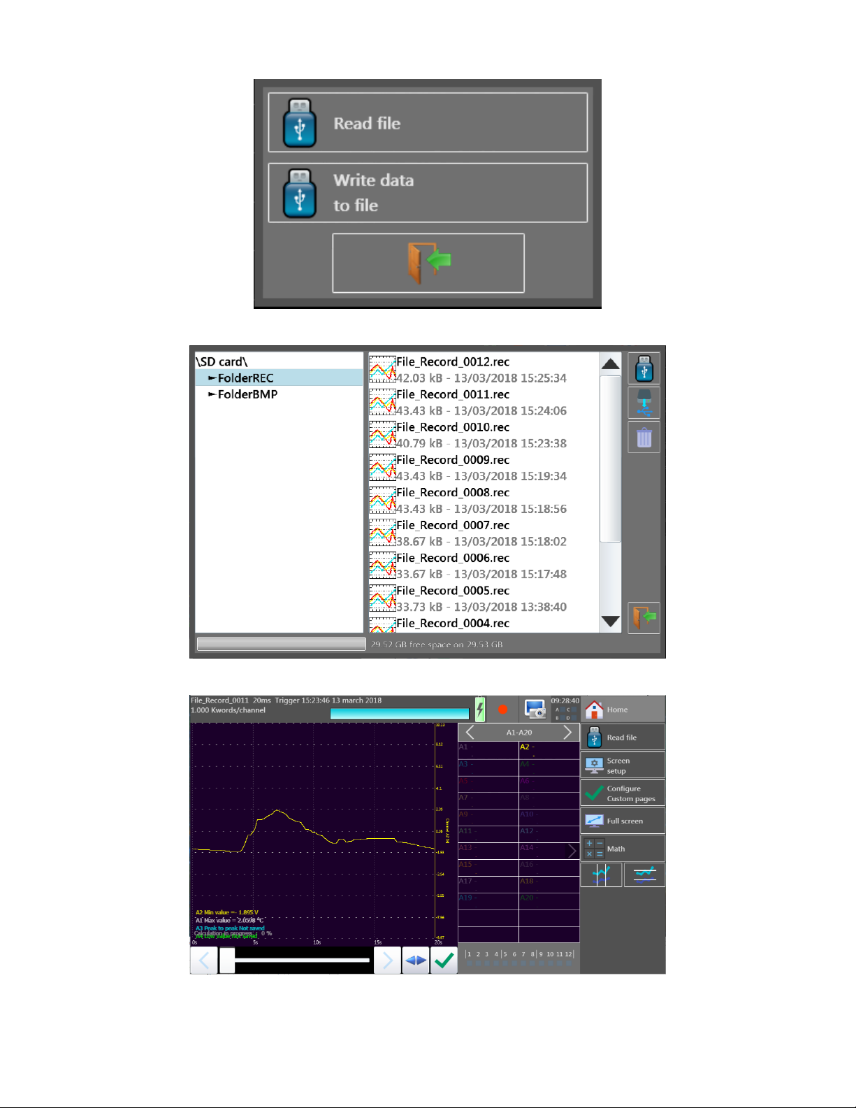
Figure 7.5 Load Saved Recording File Dialog
Figure 7.6 File Browser
Figure 7.7 Saved Recording Loaded
33
Page 37

Triggering Recordings
Item Description
1 Record le path
2 Recording size
3 Reading storage rate (reading
period)
4 Start condition
5 Stop condition
6 Trigger arm state
Figure 8.1 Trigger Menu
The start and stop functions control the conditions that initiate data recording. Opening the “Start”, or “Stop” trigger
menus open the start condition dialogs with the following recording start options:
Manual pressing a key
Trigger Based on Analog, or Digital signal conditions. See Section 8 for details
Waiting After a delay or at a specied date and hour. See Section 8.1 for details
Automatic Occurs immediately, and automatically stops when the le is full
Pre-Trigger Quantity of samples to record preceeding the trigger
8.1 Waiting Start Condition
Starting a recording at a prescribed later time or date. Figure 8.2 shows the 2 dialogs for conguring each condition.
Waiting on a delay, will wait for the prescribed time and proceed with a recording. Waiting for date delays recording until
a specic time and date. For each, congure the time in hours, mins and seconds, and for the date, the day, month and
year is also set.
8.2 Recordings
• Recording setup:
− Selection the folder
− Selection the le name (beginning of the le name, the end is an incremented numerically)
− Length of the le (maximum or selection of the number of samples per channel)
− Measurement data prior to a trigger event may be included in the data recording. The amount of data is dened
as the “Pre-trigger” samples. The amount of data is set and determines the amount of time before the trigger
event to include in the recording.
• Speed: The maximum speed is determined by the number of channels for acquisition.
34
Page 38

Wait for a Time
Wait for a Date
Figure 8.2 “Waiting” Start Conditions
• Start: Start condition of the data acquisition
• Stop: Stop condition of the data acquisition
− Automatic: when the le is full
− Trigger: on a channel or a combination of analog or logic channels
• After acquisition: action after the end of the data acquisition (only available if the Start and Stop triggers are not
set to Manual)
− Stop: no action
− Rearm: a new le is launched waiting for the Start trigger
• View of the active channels, of the recording time, of the pre-launch
Note: A message “Impossible” shows up when the saving possibilities are exceeded. Fix this by reducing the sampling
speed or the number of channels.
Various conditions are available for starting and stopping acquisition recording. Analog signals, time delays, and logic
inputs are trigger sources. Also, the amount of data prior to a trigger event is congurable. Access the trigger menu
from the “Home” screen and the “Trigger” button. Figure 8.1 is representative of the trigger conguration window.
8.3 Triggering
Triggering is based either on a single channel edges and thresholds, combinations of analog channels, or set digital signal
states.
8.3.1 Single Analog Channel Trigger
To use a single analog channel as a trigger source, the general procedure is as follows:
35
Page 39

Figure 8.3 Start Condition Dialog
1. Select trigger, and “Analog Channel” from the trigger dialog.
2. Set the amount of Pre-trigger samples to record.
3. Choose the trigger source channel.
4. Select the trigger condition (Threshold, level (higher/lower), or edge)
5. Set the trigger analog signal level.
8.3.2 Single Threshold
Figure 8.4 Trigger Threshold Setup
Channel: Selection of the channel, on which the trigger threshold is applied
Threshold 1 / Threshold 2: Selection of the threshold to settle; each channel is tested with reference with 2 thresh-
olds, i.e. you can program a start condition on the channel A1 and the threshold 1, and
a stop condition on this same channel A1 and the threshold 2
Higher / Lower: Trigger when the channel value is more or less than the set threshold
Threshold value: Threshold value selected in real value (taking the current unit and scale of the cong-
uration of the selected channel into account)
Edge: Selection of the active edge of the channel in reference to the threshold
36
Page 40

Pre-triggering (only for start): Gives the acquisition time before the trigger appears.
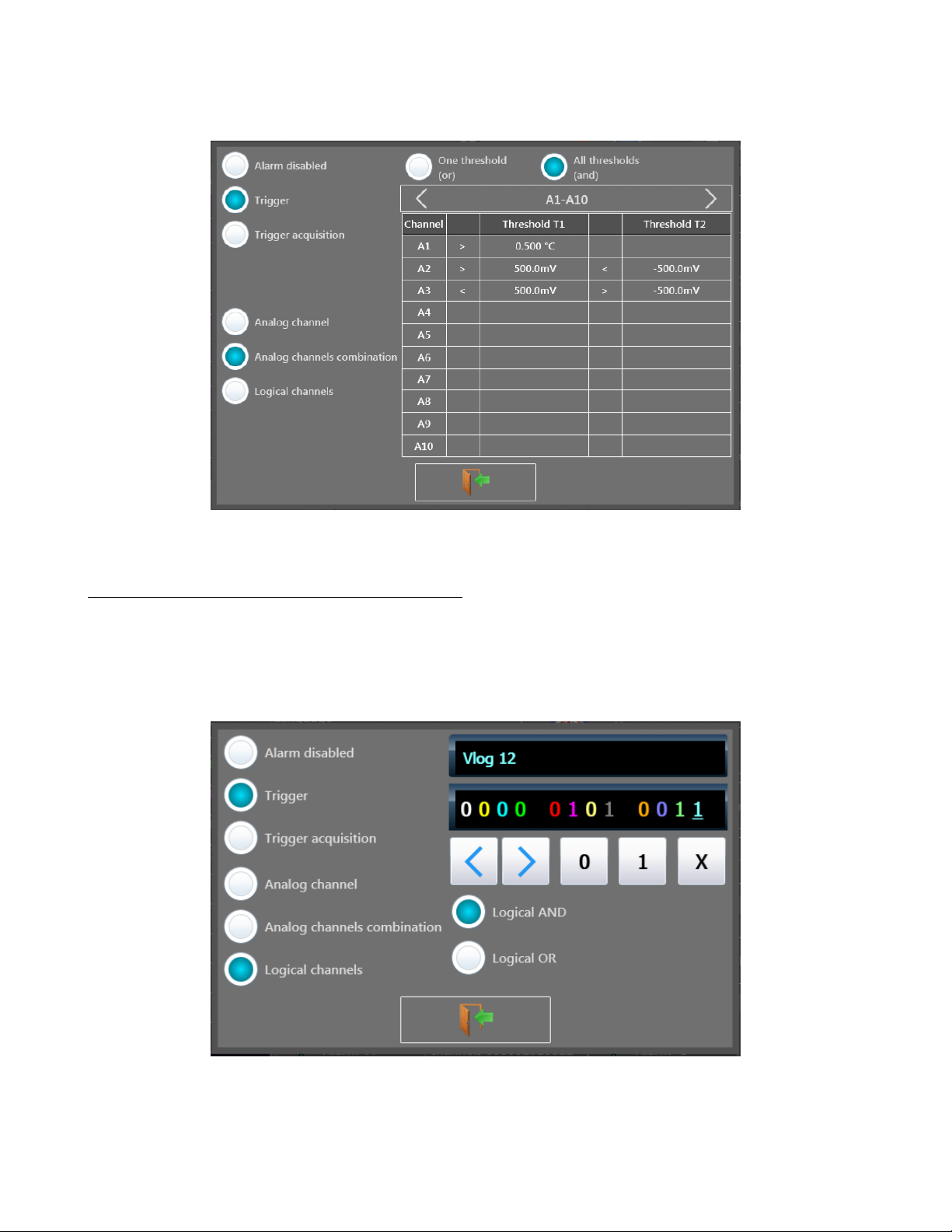
8.3.3 Multiple Thresholds
After selection of a trigger on a set of logic channels, the window allows you to set the trigger under several conditions.
Then, by pressing the various thresholds in front of their respective channels, you open the threshold parameter window.
Figure 8.5 Multiple Threshold Trigger Screen
• One of the thresholds, or the rst achieved condition activates the trigger
• All thresholds, and all conditions must be simultaneously achieved to validate the trigger
• A table makes it possible to select all channels and the validity of the channels
Selecting the channel allows the selection of the thresholds:
• S1 and S2
• Value of the thresholds
• Rising / Falling edge, or Low / High value
Figure 8.6 Trigger
Type Setup Screen
37
Page 41

8.3.4 Trigger Examples
• Edge trigger: you need a change of status
Example: Channel A1, rising edge, threshold = 0V: triggers only if the signal status changes from negative to positive
• Level trigger: no need to pass the threshold
Example: Channel A1, high level, threshold = 0V: triggers only if the signal is positive
• Alarms only have level triggers
8.4 Trigger on Logic Channels
Selecting “Logic Channels” as the trigger source changes the window to show conditions for logic channel triggering.
Each of the logic channels is congured as a 1, 0 or X (don’t care). Use the arrow keys to move through the logic input
bits. Triggering may be congured as either an AND condition or an OR condition. This is applied to each channel.
Lastly, the trigger event is generated on either a Level or Edge condition.
Logic 1 Greater than 4.0 Volts
Logic 0 Less than 1.6 Volts
Figure 8.7 Logic Trigger Setup Screen
38
Page 42

Alarms
4 congurable alarm signals allow signaling from the recorder through the digital port. The alarm signals are high (5V)
when the alarm condition is detected. The main display’s alarm status section indicates the status of the alarms. The
main display alarm status is “sticky” in that when alarm triggers, the eld is set to active (red). See Figure 9.3. The
condition may clear, and the alarm status will continue to show an alarm happened. The digital port clears the alarm
when the programmed condition is not met any longer and returns to 0V.
To congure the alarms, open the “setup” menu from the “home” screen. See Figure 9.1. At the bottom of the screen
are the 4 alarms. Each button opens the conguration dialog for that alarm. See Figure 9.2
9.1 Alarm Status
Figure 9.1 Alarms on Setup Screen
Figure 9.2 Alarm Dialog
Figure 9.3 Alarm Status
39
Page 43

The status of all 4 alarms is always visible in the top ribbon, each with its own small square. The status of each alarm
is indicated 3 colors:
Transparent Alarm disabled
Blue Alarm enabled, not triggered
Red Alarm enabled and triggered
To clear an alarm, press the on screen box containing the alarm statuses.
9.2 Analog/Math/Timing Signal Alarm
An alarm based on analog signal levels, a math function, or a “logical function” is set by selecting the “trigger” function
on the Alarm dialog (Figure 9.2). Signals available for Alarms must be active signals congured in the “Channels”
menus on the “Home” screen.
When selected, the dialog changes contents to show something similar to Figure 9.4.
Select the desired signal by pressing the button listing a channel at the center of the dialog box. Depending on the signal
type, 1 thresholds may be set. The selected threshold is show at the top of the dialog. To set the trigger as a window,
the “channels combination” conguration must be used. See Section 9.3.
Figure 9.4 Analog Alarm Trigger
Figure 9.5 Alarm
Analog Thresholds
9.3 Analog Signal Combination Alarm
More complex triggering based on windows, and combinations of signals is available. The signals are limited to the analog
channels and do not include math and timing as in the single channel alarm. The signals may have 2 thresholds.
40
Page 44
The set of signals congured will trigger the alarm if 1 threshold is true, or all thresholds are true. This is set by the
AND/OR condition at the top of the dialog.
Figure 9.6 Analog Combination Trigger
9.4 Logic (Digital) Signal Alarm Trigger
An alarm based on the logic state of the digital input is congured by selecting the “Logical Channels” option. Following
the typical convention of a 1, 0 and X to denote true, false and “dont’t care” respectively, is used to set the digital patter
to trigger on. Also, using the “AND” or “OR” conditions select when the trigger occurs. With the “AND” condition, all
signals dened must be true for the Alarm to trigger. In the “OR” case, any valid signal, excluding the “X” signals will
trigger an alarm.
Figure 9.7 Digital Trigger
41
Page 45
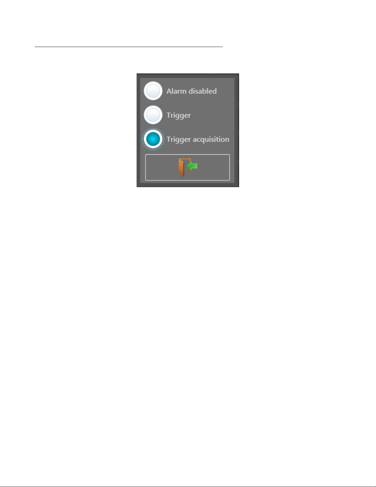
9.5 Alarm on Recording Start (Trigger Acquisition)
An alarm is also available for signaling the start of a recording. Select the “Trigger Acquisition” option to enable this
type of alarm.
Figure 9.8 Trigger on Alarm
42
Page 46

Logic Channels
Up to 12 logic channels can be recorded simultaneously with the analog channels. In addition, 4 timing channels are also
available for measuring duty cycle, RPM, and pulse count.
10.1 Logic Input Connector
This is a DB-25 connector located on the top of the unit.
Pin Signal Pin Signal
13 Logic Ch 1 19 Function K2
25 Logic Ch 2 6 Function K3
12 Logic Ch 3 18 Function K4
24 Logic Ch 4 5 Ground
11 Logic Ch 5 17 Ground
23 Logic Ch 6 4 Ground
10 Logic Ch 7 16 9-15V 0.2A
22 Logic Ch 8 3 Ground
9 Logic Ch 9 15 Alarm C
21 Logic Ch 10 2 Alarm D
8 Logic Ch 11 14 Alarm A
20 Logic Ch 12 1 Alarm B
7 Function K1
Figure 10.1 Logic Connector
10.2 Logic Channel Setup
To set the logic channels, press the “logic channels” button on the “Home” screen, or from the “F(t)” screen, click within
the logic signal portion of the screen when present, See Figure 10.2. The conguration screen will open and resemble
Figure 10.3.
The set of channels depends on the number of channels chosen. For a given number of channels, the signals enabled on
the connector is xed. For example, if 4 channels are enabled by the up/down arrows beside the text listing the number
of channels, then pins 13, 25, 12, and 24, will be active. They become channels 1-4 respectively.
Figure 10.2 Logic
Channels on the F(t) screen
43
Page 47

Item Description
1 Channel number, color and arrows to
change channel
2 Channel count
3 Enable logic channels
4 Connector (red - selected channel)
5 Additional pin information
6 Channel #, pin, and state (dim -
disabled)
Figure 10.3 Logic Channel Conguration Screen
10.3 Timing
Function channels K1-4 are used for measuring the PWM duty cycle, count, or frequency of up to 4 digital signals. They
are also 3.3V level signals and tolerant of 24V.
Access the setup for these functions from the “Home” screen and pressing the . Then navigate to the
channels K1-4. See Figure 10.4. To congure each channel, either change the parameters on this screen by opening the
menus per eld in the table, or open the conguration screen for a single channel by pressing the channel ID (i.e. K1).
Conguration of a single channel is done via screens similar to Figure 10.5.
Figure 10.4 Timing Function Channels
10.4 Alarm Outputs
Finally, the “Alarm” signals are also present on the Logic connector (A, B, C and D. Pins 14, 1, 15 and 2 respectively).
Their setup and use is described in Section 9. All outputs are TTL 5V. When the unit is powered off, outputs have a
5kΩresistance.
44
Page 48

Figure 10.5 Single Timing Function Setup Screen
45
Page 49

File Management
The recorder is capable of creating recordings, screenshots, and saving device setup congurations. All of these are
stored as les, “*.rec” for recordings, “*.bmp” for screenshots, and “*.cfg” les for congurations. The le view dialog
Figure 11.1 is accessible from the “Home>Setup”, “(Waveform)>Screen Setup>Background”, “Home>View Records”,
“Home>Setup>Load/Save on Disk” screens for example. Each instance of the le dialog allow interaction between
internal and external (USB) storage. Finally, folder navigation and creation is also available.
1 Note:
It is highly advisable to work in a folder and not at the root of the ash disk. When erasing a folder, all les in this
directory will be erased too.
Figure 11.1 File View Screen
1. Read/write to internal ash disk or USB stick (if it was connected during unit startup)
2. Copy the selected le or folder to a USB drive
3. Create and name a new le
4. Create a new folder
5. Delete the selected folder or le
6. Close the window
7. Folder navigation and location window
8. File view and selection window
11.1 Setup Files
Setup congurations are loaded and saved from the “Home>Setup” menu. The conguration may be changed via the 3
buttons in the upper righthand corner of the screen:
46
Page 50

Default Sets up the appliance in standard conguration
Load from disk Loads a conguration from a le in the internal ash disk or an USB stick
Save to disk Saves a conguration into a le in the internal ash disk or an USB stick
These commands are only available when the data recording is stopped.
11.1.1 Default
This action loads the system defaults as programmed into the unit during manufacturing.
11.1.2 Save Setup Files
To save a conguration, press the . The name of the le with the alphanumerical keyboard
displayed on screen, or, if attached, a USB keyboard.
11.1.3 Load Setup Files
To load a conguration, press the . Select the directory and then the le to load, and click “Load”.
11.2 Recordings Files
Saved recordings are transferable between internal storage and USB. Recordings are saved to internal storage. See
Chapter 7 for details.
47
Page 51

Remote Interfaces
12.1 LAN Interface
The LAN connection to the DAS240-BAT supports ModBus, VNC, Sefram Viewer and DAS Lab. Sefram Viewer and
DAS Lab are tools provided by B&K/Sefram, and are available as a single download from http://www.bkprecision
.com. The LAN connection supports 10mBit and 100mBit networks. In the case where a network is not available, using
a crossover cable is also possible.
12.1.1 LAN Setup
Setup of the LAN interface is available by clicking the “Network” button on the “Home” screen. (See Figure 12.1).
Clicking the “Network” button opens the network setup dialog (See Figure 12.2). The LAN interface supports static
and dynamic (DHCP) conguration. For DHCP, the DHCP checkbox is marked, and the network address will be shown
on the “Network” button shown on the “Home” screen. For static IP conguration, using parameters dened for the
network (see your local network administrator for details) are set in the dialog.
Figure 12.1 LAN Conguration Button
12.2 VNC
Use of the unit from another computer is available using VNC (Virtual Network Computing). This presents an interactive
view of the front panel allowing nearly all functions to be used remotely. Numerous software tools are available for using
VNC (ex. UltraVNC).
To open a connection, the IP address of the unit is required. This is found on the “Network” button on the “Setup”
screen.
12.2.1 Changing the Password
Open the “Setup” screen and press the “VNC” button. The resulting dialog box shows the current password. Press the
keyboard icon in order to change the password.
12.3 Network File Transfer
Transfer your les to your computer to save them or view them with the SeframViewer software.
• Using of the Windows le explorer
• Filezilla: freeware (https://lezilla-project.org/)
• Using an external browser (Firefox, Chrome, Edge, etc…)
48
Page 52

DHCP Static
Figure 12.2 LAN Setup
12.4 Viewing with SeframViewer
You can transfer the data acquisition les to a PC computer for viewing.
The SeframViewer software is provided on a CD-ROM with the appliance. You can use it to view the recorded les or
convert it into xls or txt les.
It works under WINDOWS with Framework 2.0.
Transfer of the les from the appliance to the PC computer:
• USB peripheral device
• with the FTP protocol
Launch the SeframViewer software (or double-click on a le)
Open a data acquisition le (sux .rec)
You can select:
• the channels to display
• the display mode f(t) or xy
• the self-calibration of the channels.
Your data acquisition le shows up on screen. The functions of SeframViewer are available.
Refer to the instruction manual included in the software to discover all available functions in SeframViewer by clicking
on the last icon < Help >.
You can also directly create a le (.txt or .xls) by launching the command mode of Windows with the following line (see
the Options sub-menu of the help):
49
Page 53

Figure 12.3 Sefram Viewer
12.4.1 Example
C:\Program Files (x86)\SeframViewer\seframviewer.exe myle.rec /x
will create a .xls le
C:\Program Files (x86)\SeframViewer\seframviewer.exe myle.rec /t
will create a .txt le
Excel@export will directly launch Excel in the browser.
Figure 12.4 Excel Export
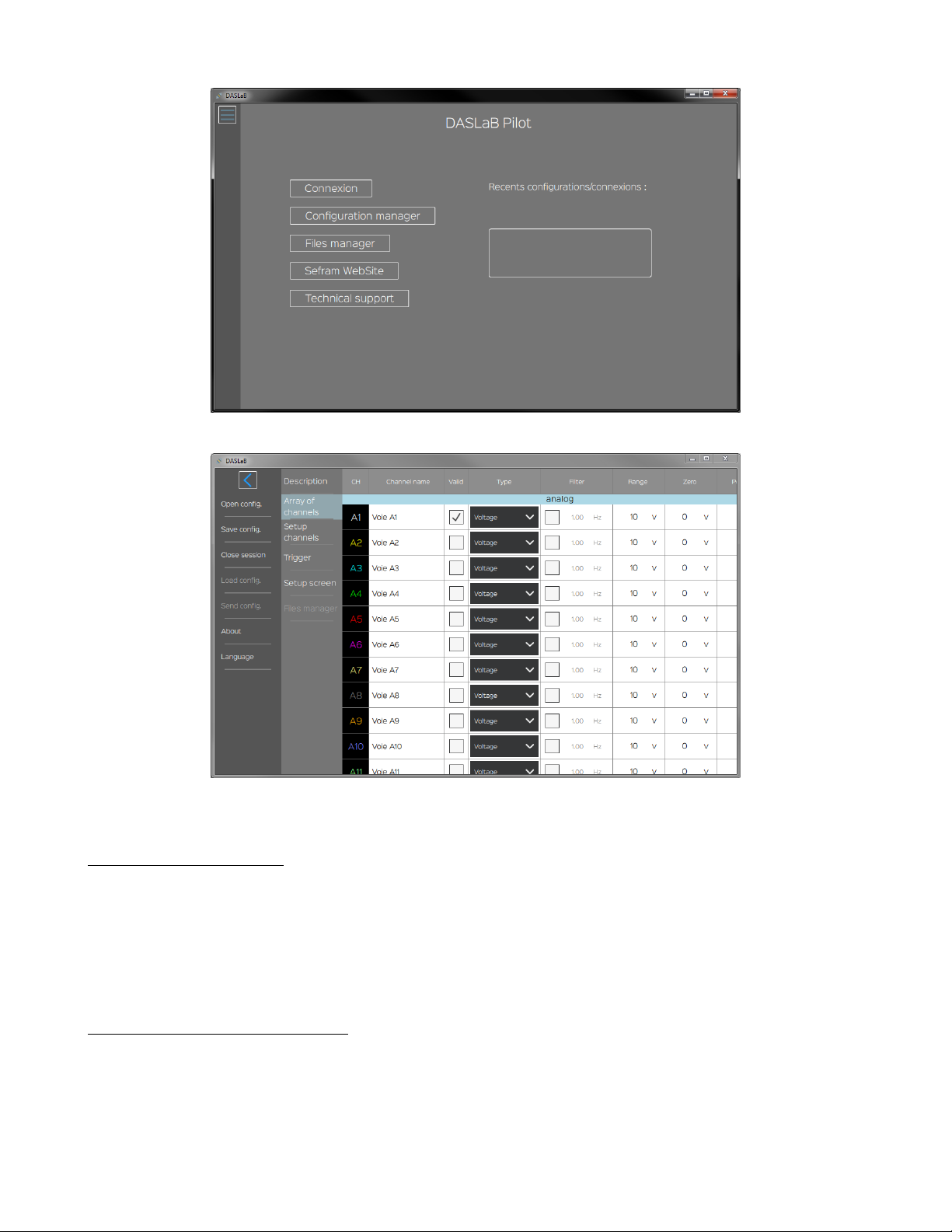
12.5 Device Control with DASLab
The DASLaB software manages congurations of your DAS240-BAT device.
• Open, modify and save your congurations
• Manage congurations remotly using network via Ethernet or WiFi
• Download your record les using network via Ethernet or WiFi
According to your needs, click on the right button. If you want manage your DAS240-BAT or DAS220-BAT using
network, enter the IP address to establish the connection.
For every action, including opening, saving, sending or refreshing congurations, the left sliding menu makes you able to
apply it.
50
Page 54
12.6 Modbus (slave)
Figure 12.5 DASLab
Figure 12.6 DASLab
Modbus is a non-proprietary communication protocol. All Modbus frames are encapsulated into Ethernet frames: it is
called Modbus over TCP/IP.
That protocol is dialog based (question-answer) : the client (master) send a command, and then the server (slave), send
back wanted data.
The DAS240-BAT/DAS220-BAT includes a Modbus TCP Slave service.
12.6.1 Setup Modbus Slave
The Modbus protocol uses ethernet network. So you have to choose the port used for that feature, and then enable the
Modbus TCP server.
Default port for Modbus TCP is 502.
It is possible to use Wi provided a USB Wi adapter is installed and working: for performance reasons however, the
wired USB interface should be used when using Modbus.
51
Page 55

In the Setup page of your instrument, then Additional option, select the “Modbus TCP Server” button.
You could enable or disable the server: click on the radio button < Modbus server state >.
According to your preferences, you are able to change the network port dedicated to the Modbus server. To carry out
that change to a successful conclusion, you must disable the Modbus server, change the port (502 by default), and then
restart the Modbus server.
12.6.2 Mapping Modbus TCP
The instrument shares acquisition data at input registers (0x04) and discrete input (0x02).
12.6.2.1 Analog Data
Acquisition data for the 200 analogs channels, and 4 logicial functions channels (K1 to K4) are located in inputs registers
from the following address : 0x08.
Register Register Description
0x08 A1 High word
0x09 A1 Low word
0x0A A2 High word
0x0B A2 Low word
… …
0x19F K4 High word (channel n* 204)
0x1A0 K4 Low word
Table 12.1 Modbus register map
An input register contains 16 bits, and each channel value is represented as a oat (32 bits).
So, to read one channel, you should read two input registers.
Example : Input A1 from address 0x08 to 0x09
At address 0x08 : -16460 (16 bits)
At address 0x09 : 28160 (16 bits)
Value in oat : -1.40961 (32 bits)
12.6.2.2 Logical Data
Logical values about the 12 logical channels are located in the discrete inputs from the address 0x08.
Register Register Data
0x08 DI1
… …
0x14 DI12
Table 12.2 Register Mapping
52
Page 56

Maintenance
Unplug the unit before any cleaning or maintenance.
Periodically clean the recorder while unplugged, in the following ways:
• Use water and soap to clean the front and rear surfaces.
• Never use any product that contains petroleum by-products, benzene or alcohol: damage the screen printings may
occur
• Wipe with a soft lint-free cloth.
• Use an antistatic product to clean the screen.
13.1 Updating the Internal Software
The internal software is updated regularly with the latest evolutions. These updates are available on our website.
http://www.sefram.com/en/software-updates.html
• To update the software, copy the le that will be provided on an USB stick. Place it on the USB connector on the
rear side of the unit.
• Press the “Setup” key.
• Then press the “Software update” key to enter the update.
• Finally, to run the update, press the “Sofware update” key.
• Then, the internal software automatically copies the necessary les to the new version.
• Turn the unit off and on after the end of the updating process.
53
Page 57

Specications
Note: All specications apply to the unit after:
1. A temperature stabilization time of 15 minutes over an ambient temperature range of 23
2. Short correction operation performed before making measurement.
Specications are subject to change without notice.
∘
C ± 5
∘
C.
54
Page 58

Portable 10-channel data recorder
Model DAS220-BAT
5
www.bkprecision.com
v041519
Specifications
Analog Channels
Analog Input Channels 10 integrated channels
DC Voltage
Ranges
± (0.5, 1, 2.5, 5, 10, 25, 50, 100) mV
± (0.5, 1, 2.5, 5, 10, 25, 50, 100) V
Maximum input Voltage 100 V DC
Accuracy 0.1% of the full scale ±10 µV
Temperature with Thermocouples
Sensors Range by
Type (Cold junction
compensation: ±0.5 °C)
J -210 °C to 1200 °C
K -250 °C to 1370 °C
T -200 °C to 400 °C
S -50 °C to 1760 °C
B 200 °C to 1820 °C
E -250 °C to 1000 °C
N -250 °C to 1300 °C
C 0 °C to 2320 °C
L -200 °C to 900 °C
Temperature with Pt100 and Pt1000
Current 1 mA (Pt100), 100 µA (Pt1000)
Range -200 °C to 850 °C
Measurements 2 and 3 wires
Accuracy (at 20 °C) 0.3 °C ±0.1% of reading
Compensated Resistance
2 wires 30 Ω max.
3 wires 50 Ω max.
Resistance
Ranges 1 kΩ and 10 kΩ
Accuracy 1 Ω (range 1 kΩ) and 10 Ω (range 10 kΩ)
Acquisition System
Resolution 16 bit
Acquisition System Scan, one sample per channel
Sampling Interval
V >50 mV 1 ms to 20 min
V ≤50 mV,
thermocouples and
Pt100 / Pt1000
2 ms to 20 min
Trigger
Date, delay, threshold, combination of
thresholds (and/or), word on logic
channels (and, or, slope, level)
Pre-trigger Variable from 0 to 100k samples
General
Internal Flash Drive Size 32 GB
Maximum File Size 2 GB
Operating Temperature 0 °C to 40 °C, 80% RH (no condensation)
Storage Temperature -20 °C to 60 °C
Display
10” TFT touchscreen LCD,
backlit, 1024 x 600 dots
Power Supply
15 V / 4 A max with main adapter
(100 / 240 VAC)
Interfaces
2 x USB host,
LAN (10/100 base-T with RJ45 socket)
Battery Non removable, Lithium-ion
Typical Battery Life
15 hours with standby mode, 10 hours without
stand-by mode
Safety Cat I 100 V, according to IEC61010-1
Weight 3.3 lbs (1.5 kg)
Dimensions (W x H x D) 2.6” x 11.7” x 6.9” (66 x 298 x 176 mm)
Warranty Two Years
Supplied Accessories
Main adapter 100 / 240 V, manual (CD-ROM),
25 pin male connector
(1)
and backshell, 10 input
connectors, shoulder strap, stylus, soft wipe,
and screwdriver
Order Information for Optional Accessories
902401050 Analog input terminal blocks 20 pack
902408000 Rugged carrying case
902407000 Logic channels patch cord
902406500 4 to 20 mA / 50 Ω shunt
902409000 19” rack-mount kit
Logic Channels
Logic Input/Output
Number of Channels 12
Maximum Permitted Voltage 24 V Cat I
Input Impedance 4.7 kΩ
Sampling Rate 1 ms max.
Timing Input
Number of Channels 4 (K1 to K4)
Maximum Permitted Voltage 24 V Cat I
Input impedance 4.7 kΩ
Sampling Rate 1 ms max.
Pulse Counter 0 to 10 Million, accuracy 1 ppm
Frequency Measurement 1 Hz to 10 kHz, accuracy 0.1%
PWM Measurement 100 Hz to 2 kHz, accuracy 0.1%
Alarm Output
Number of Channels 4 Alarms (A, B, C, D)
Output Level 0 to 5 V
Note: All specifications apply to the unit after a temperature stabilization time of 30 minutes
over an ambient temperature range of 23 °C ± 5 °C.
(1) User configurable with solder cups.
Page 59

Multi-channel recorder
Model DAS240-BAT
5
www.bkprecision.com
v032318
Specifications
Analog Channels
Number of Analog Input Channels
20 channels standard, expandable to 200 with optional 20-channel modules
DC Voltage
Ranges
± (0.5, 1, 2.5, 5, 10, 25, 50, 100) mV
± (0.5, 1, 2.5, 5, 10, 25, 50, 100) V
Maximum input Voltage 100 V DC
Accuracy 0.1% of the full scale ±10 µV
Temperature with Thermocouples
Sensors Range by
Type (Cold junction
compensation: ±0.5 °C)
J -210 °C to 1200 °C
K -250 °C to 1370 °C
T -200 °C to 400 °C
S -50 °C to 1760 °C
B 200 °C to 1820 °C
E -250 °C to 1000 °C
N -250 °C to 1300 °C
C 0 °C to 2320 °C
L -200 °C to 900 °C
Temperature with Pt100 and Pt1000
Current 1 mA (Pt100), 100 µA (Pt1000)
Range -200 °C to 850 °C
Measurements 2 and 3 wires
Accuracy (at 20 °C) 0.3 °C ±0.1% of reading
Compensated Resistance
2 wires 30 Ω max.
3 wires 50 Ω max.
Resistance
Ranges 1 kΩ and 10 kΩ
Accuracy 1 Ω (range 1 kΩ) and 10 Ω (range 10 kΩ)
General
Acquisition System
Resolution 16 bit
Acquisition System Scan, one sample per channel
Sampling Rate
V >50 mV 1 ms to 20 min
V ≤50 mV,
thermocouples and
Pt100 / Pt1000
2 ms
Trigger
Date, delay, threshold, combination of
thresholds (and/or), word on logic
channels (and, or, slope, level)
Pre-trigger Variable from 0 to 100k samples
Internal Storage
Internal Flash Drive Size 32 GB
Maximum File Size 2 GB
Environmental
Operating Temperature 0 °C to 40 °C, 80% RH (no condensation)
Storage Temperature -20 °C to 60 °C
Auxiliary
Display
10” TFT touchscreen LCD,
backlit, 1024 x 600 dots
Power Supply
15 V / 4 A max with main adapter
(100 / 240 VAC)
Interfaces
2 x USB host,
LAN (10/100 base-T with RJ45 socket)
Battery Non removable, Lithium-ion
Typical Battery Life
15 hours with standby mode, 10 hours without
stand-by mode
Safety Cat I 100 V, according to IEC61010-1
Weight 3.3 lbs (1.5 kg)
Dimensions (W x H x D) 2.6” x 11.7” x 6.9” (66 x 298 x 176 mm)
Warranty Two Years
Supplied Accessories
Main adapter 100 / 240 V, manual (CD-ROM),
1 male connector with 25 pins male and cover,
1 cable (70 cm) for measurement module
connection, 1 measurement module (20
channels) with input terminals, a stylus,
a soft wipe, a screwdriver
Order Information for Optional Accessories
902401000 20-channel module
902401050 Input terminal blocks 20 pack
902408000 Rugged carrying case
902407000 Logic channels patch cord
902406500 4 to 20 mA / 50 Ω shunt
902409000 19” rack-mount kit
Logic Channels
Logic Input/Output
Number of Channels 12
Maximum Permitted Voltage 24 V Cat I
Input Impedance 4.7 kΩ
Sampling Rate 1 ms max.
Timing Input
Number of Channels 4 (K1 to K4)
Maximum Permitted Voltage 24 V Cat I
Input impedance 4.7 kΩ
Sampling Rate 1 ms max.
Pulse Counter 0 to 10000000, accuracy 0.1%
Frequency Measurement 1 Hz to 10 kHz, accuracy 0.1%
PWM Measurement 100 Hz to 2 kHz, accuracy 0.1%
Alarm Output
Number of Channels 4 Alarms (A, B, C, D)
Output Level 0 to 5 V
Page 60

Thermocouple Measurement Accuracy
The thermocouple measurements are treated as voltage measurements.
For a given range of temperature measurement, the software calculates the voltage caliber the following way:
• Let < T > the absolute value of the max. measurable value, in
• Add 40
• Search the corresponding voltage value U in the table of thermocouples
• Program the caliber with U included in the range.
∘
C to take the max. cold welding temperature into account
∘
C
15.1 J Type Thermocouple Example
You want to program a measurement range between -50 and + 50∘C with a J thermocouple:
• Max. absolute value T = 50
• Add 40
• Corresponding U voltage according to the tables ThJ U = 4.726 mV
• Programmed caliber: 10 mV (measurement range: -5mV to +5mV)
The measurement inaccuracies below are max. values: the typical values are half to thrice as much.
The temperature measurement accuracy is the sum of several possible uncertainty causes:
• Pl: linearization accuracy
∘
C T + 40 = 90∘C
∘
C
• Ps: weld welding accuracy
• Pm: measurement accuracy of the equivalent voltage
The total accuracy Pt is then: 𝑃𝑡=𝑃𝑙+𝑃𝑠+𝑃𝑚
For the recorder:
• Pl = + 0.25
• Ps = + 0.5
• Pm = 0.1% of the voltage caliber + 10𝜇V) divided by the slope of the thermocouple in 𝜇V/
∘
C for all thermocouples
∘
C for all thermocouples
∘
C
15.2 Measurement Accuracy: Pm
The measurement accuracy Pm depends on the voltage caliber of the appliance (see the previous paragraph) and on
the slope of the thermocouple. You shall take the slope at 0∘C while knowing that it will vary as a function of the
temperature, but this variation is generally of the second order for the accuracy calculation.
15.3 Voltage of Thermocouple (mV)
Slope of the thermocouples (𝜇V)
55
Page 61

• At 100∘C the slope of thermocouple J is 55𝜇V
• At -100∘C slope is 30𝜇V .
• So the error is 2 time greater then 100
∘
C to -100∘C.
15.3.1 Example of Accuracy Calculation
You make a welding between -50∘C and +50∘C with a J thermocouple with compensation of cold welding.
𝑃𝑡=𝑃𝑙+𝑃𝑠+𝑃𝑚 (15.1)
Linearization accuracy 𝑃𝑙=+0.25∘𝐶
Compensation of cold welding 𝑃𝑠=+0.5∘𝐶
Used caliber 10mV - (see previous example)
Accuracy for voltage measurement 0.1%∗10𝑚𝑉 +10𝜇𝑉 =20𝜇𝑉
Slope of J thermocouple 50𝜇𝑉/∘𝐶
Accuracy Pm 𝑃𝑚=20/50=0.4∘𝐶
Total accuracy 𝑃𝑡=0.25+0.5+0.4=1.15∘𝐶
15.4 Accuracy Class - Class Index
This is one of the most important concepts of the CEI recommendation; it tends to shorten the list of specications. To
do so, it introduces the concept of PREDICTIVE CLASS that depends on the C CLASS INDEX.
The normalized values of the class index are: C = 0.1, 0.25, 0.5 and 1.
The intrinsic error (in the reference conditions) does not exceed + C% (the manufacturer may also specify this limit of
the intrinsic error as an absolute value (ex. + 5 𝜇V) for the rst calibers).
The variations (of the measured value) with the variations of one of the inuential variables in the nominal range of use
do not exceed:
• C % for the position for the magnetic induction with external source and parasite voltages
• 0.5 C% for the power supply source
• 0.3 C% according to the class index at ambient temperature (0.15% for the 0.25 class).
In addition, the insensitivity range should not exceed:
• C% in the reference conditions
• 1.5C% for the maximal resistance of the external measurement circuit
• 2C% for parasite voltages
And the excess should not be more than 2C% (4C% within the limits of the power supply source). %
56
Page 62

15.5 Grounding
• If the source of the signal you have to record has low internal impedance, you shall use twisted wires. In case of high
impedance, you shall use shielded wires.
• When gathering grounds from the various items on the measurement line, it is good to check that there is no voltage
difference between them, in order to prevent any shortcut. If any doubt, make a measurement with a voltmeter on a
low resistance (i.e. 1kΩ) between the terminals.
• If any important noise,
− When using the battery , connect the GND connection to the ground
− use the sampling period for each channel >20ms
− an appropriate capacity can be placed between the ground and the - wire of the signal.
57
Page 63

LIMITED TWO-YEAR WARRANTY
B&K Precision Corp. warrants to the original purchaser that its products and the component parts thereof, will be free
from defects in workmanship and materials for a period of two years from date of purchase.
B&K Precision Corp. will, without charge, repair or replace, at its option, defective product or component parts. Returned
product must be accompanied by proof of the purchase date in the form of a sales receipt.
To help us better serve you, please complete the warranty registration for your new instrument via our website www.bkprecision.com
Exclusions: This warranty does not apply in the event of misuse or abuse of the product or as a result of
unauthorized alterations or repairs. The warranty is void if the serial number is altered, defaced or removed.
B&K Precision Corp. shall not be liable for any consequential damages, including without limitation damages resulting
from loss of use. Some states do not allow limitations of incidental or consequential damages. So the above limitation
or exclusion may not apply to you.
This warranty gives you specic rights and you may have other rights, which vary from state-to-state.
B&K Precision Corp.
22820 Savi Ranch Parkway
Yorba Linda, CA 92887
www.bkprecision.com
714-921-9095
58
Page 64

Service Information
Warranty Service: Please go to the support and service section on our website at bkprecision.com to obtain an RMA
#. Return the product in the original packaging with proof of purchase to the address below. Clearly state on the RMA
the performance problem and return any leads, probes, connectors and accessories that you are using with the device.
Non-Warranty Service: Please go to the support and service section on our website at bkprecision.com to obtain an
RMA #. Return the product in the original packaging to the address below. Clearly state on the RMA the performance
problem and return any leads, probes, connectors and accessories that you are using with the device. Customers not on
an open account must include payment in the form of a money order or credit card. For the most current repair charges
please refer to the service and support section on our website.
Return all merchandise to B&K Precision Corp. with prepaid shipping. The at-rate repair charge for Non-Warranty
Service does not include return shipping. Return shipping to locations in North America is included for Warranty Service.
For overnight shipments and non-North American shipping fees please contact B&K Precision Corp.
B&K Precision Corp.
: 22820 Savi Ranch Parkway
Yorba Linda, CA 92887
bkprecision.com
714-921-9095
Include with the returned instrument your complete return shipping address, contact name, phone number and description
of problem.
Version: April 25, 2019
59
 Loading...