


Model: XLN3640, XLN6024, XLN8018, XLN10014
High Power Programmable
DC Power Supply
Click for models XLN15010, XLN30052 & XLN60026
USER MANUAL
Test Equipment Depot - 800.517.8431 - 99 Washington Street Melrose, MA 02176
TestEquipmentDepot.com

Safety Summary
The following safety precautions apply to both operating and maintenance personnel
and must be observed during all phases of operation, service, and repair of this
instrument. Before applying power, follow the installation instructions and become
familiar with the operating instructions for this instrument.
Failure to comply with these precautions or with specific warnings elsewhere in this
manual violates safety standards of design, manufacture, and intended use of the
instrument. B&K Precision assumes no liability for a customer’s failure to comply
with these requirements. This is a Safety Class I instrument.
GROUND THE INSTRUMENT
To minimize shock hazard, the instrument chassis and cabinet must be
connected to an electrical ground. This instrument is grounded through the
ground conductor of the supplied, three-conductor ac power cable. The
power cable must be plugged into an approved three-conductor electrical
outlet. Do not alter the ground connection. Without the protective ground
connection, all accessible conductive parts (including control knobs) can
render an electric shock. The power jack and mating plug of the power cable
meet IEC safety standards.
DO NOT OPERATE IN AN EXPLOSIVE ATMOSPHERE
Do not operate the instrument in the presence of flammable gases or fumes.
Operation of any electrical instrument in such an environment constitutes a
definite safety hazard.
KEEP AWAY FROM LIVE CIRCUITS
Instrument covers must not be removed by operating personnel. Component
replacement and internal adjustments must be made by qualified maintenance
personnel. Disconnect the power cord before removing the instrument
covers and replacing components. Under certain conditions, even with the
power cable removed, dangerous voltages may exist. To avoid injuries,
always disconnect power and discharge circuits before touching them.
DO NOT SERVICE OR ADJUST ALONE
Do not attempt any internal service or adjustment unless another person,
capable of rendering first aid and resuscitation, is present.

DO NOT SUBSTITUTE PARTS OR MODIFY THE INSTRUMENT
tive ground
connection, all accessible conductive parts (including control knobs)
can render an electric shock. The power jack and mating plug of the
before
Before connecting the line cord to the AC mains, check the rear panel
AC line voltage indicator. Applying a line voltage other than the
fuses. For continued fire
protection, replace fuses only with those of the specified voltage and
This product uses components which can be damaged by
static discharge (ESD). To avoid damage, be sure to follow
ocedures for handling, storing and transporting parts and
Do not install substitute parts or perform any unauthorized modifications to
this instrument. Return the instrument to B&K Precision for service and
repair to ensure that safety features are maintained.
WARNINGS AND CAUTIONS
WARNING and CAUTION statements, such as the following examples,
denote a hazard and appear throughout this manual. Follow all instructions
contained in these statements.
A WARNING statement calls attention to an operating procedure, practice, or
condition, which, if not followed correctly, could result in injury or death to
personnel.
A CAUTION statement calls attention to an operating procedure, practice, or
condition, which, if not followed correctly, could result in damage to or
destruction of part or all of the product.
WARNING: Do not alter the ground connection. Without the protec
power cable meet IEC safety standards.
WARNING: To avoid electrical shock hazard, disconnect power cord
removing covers. Refer servicing to qualified personnel.
CAUTION:
indicated voltage can destroy the AC line
current ratings.
CAUTION:
electroproper pr
subassemblies which contain ESD-sensitive components.

Store/Move/Maintain
Storage
When this device is not in use, properly package it and store it in an
environment suitable for storage (if present in a good preserving environment,
the packaging process can be waived).
Freight
While moving this product, move it by using the original packaging to pack
this product in advance. If the packaging material is lost, use an equivalent
buffer material to replace it in packaging; and with external marks indicating
“fragile & water-prevention”.
Maintenance
Please return the power supply to factory for any repair, service, or
maintenance.
Disposal
When the device is in an unusable condition and can’t be repaired, please
discard it according to your company’s disposal procedures or local legal
procedures. Don’t discard arbitrarily to avoid polluting the environment.
1

Table of Contents
1. Preface ...................................................................................................... 1
1.1 Products Outline ................................................................................ 1
1.2 Features ............................................................................................. 2
1.3 Specifications .................................................................................... 4
2. Cautions Before Using ............................................................................ 9
2.1 Check and Confirm Accessories before Using .................................. 9
2.2 Operation Instructions ....................................................................... 9
2.3 Ambient Environment ....................................................................... 9
2.4 Storage ............................................................................................. 10
2.5 Power-line voltage ........................................................................... 10
2.6 Fuses ................................................................................................ 10
2.7 War m -up Time ................................................................................. 11
2.8 Power-off procedure ........................................................................ 11
2.9 Cautions in Operation ...................................................................... 11
3. Front Panel Operation .......................................................................... 12
3.1 XLN3640/XLN6024/XLN8018/XLN10014 Panel ......................... 12
3.1.1 Front Panel ................................................................................. 12
3.1.2 Rear Panel .................................................................................. 30
4. Operation Instructions ......................................................................... 34
4.1 Voltage Setting................................................................................. 34
4.2 Current Setting ................................................................................ 34
4.3 Over-voltage Protection OVP .......................................................... 34
4.4 Over-current Protection OCP .......................................................... 34
4.5 Voltage Output ................................................................................. 35
2

4.6 Control Voltage Output with Rotary knob ....................................... 35
4.7 Timer Function ................................................................................ 35
4.8 Series (cascade) / Parallel Mode Setting ......................................... 36
4.8.1 Parallel Connection Setting ........................................................ 36
4.8.2 Series Mode Setting ................................................................... 38
4.8.3 Error Message of Series/Parallel Connection ............................ 41
4.9 External Tuning Setting ................................................................... 42
4.10 Timer of Current Flow ..................................................................... 43
4.11 Programmable Capability (SCPI Command Only) ......................... 44
4.12 Multi-unit Connection mode (RS485) ............................................. 50
5. Protection and Error Messages............................................................ 54
5.1 Over-voltage Protection (OVP) ....................................................... 54
5.2 Over-current Protection (OCP) ........................................................ 54
5.3 Overpower Protection (OPP) ........................................................... 54
5.4 Constant Voltage Protection (CV TO CC) ....................................... 55
5.5 Constant Current Protection (CC TO CV)....................................... 55
5.6 Over-temperature Protection (OTP) ................................................ 55
5.7 Low Voltage Protection (ACD) ....................................................... 56
5.8 Error Input Message ........................................................................ 56
6. Remote Interface communication protocol ........................................ 57
6.1 Prefaces ........................................................................................... 57
6.2 Parameters Definition ...................................................................... 57
6.3 The Error/Event List ........................................................................ 58
6.4 Remote Communication Protocol ................................................... 59
6.5 SCPI Conformity Information ......................................................... 62
6.5.1 Common SCPI commands ......................................................... 62
6.5.2 SCPI Command subsystem ........................................................ 63
3

6.6 State Bit Definition .......................................................................... 74
6.7 LAN Communication (-GL versions) .............................................. 75
Using Web Server........................................................................................... 75
Main Page (Home) .................................................................................. 75
Using Telnet ............................................................................................ 78
Using Sockets .......................................................................................... 78
7. Assemble Accessories ............................................................................ 79
7.1 Assemble Rack Mount Brackets ..................................................... 79
7.2 Assembly of Output Protective Cover
(XLN6024/XLN8018/XLN10014) .................................................. 80
7.3 Assembly of Remote Sense Protective Cover
(XLN6024/XLN8018/XLN10014) .................................................. 81
8. Accessories ............................................................................................. 82
Test Equipment Depot - 800.517.8431 - 99 Washington Street Melrose, MA 02176
TestEquipmentDepot.com
4

1. Preface
1.1 Products Outline
B&K Precision models XLN3640/XLN6024/XLN8018/XLN10014 are
programmable DC power supplies with single outputs that offer the
maximum power output up to 1440 watts (0 -- 36 V/40 A or 0 -- 60 V/24 A
or 0 -- 80 V/18 A or 0 -- 100 V/14.4 A). With a 16-bit D/A, A/D converter
embedded, the power supplies come with the resolution of 1mV in voltage
setting and 1mA in current setting. By connecting up to 4 power supplies in
parallel or series, a maximum power output up to 5760 watts can be
generated. With four XLN10014 connected in series, the maximum output
voltage can reach 400 V. With four XLN3640 connected in parallel, the
output current can reach up to 160 A.
The XLN series provides a rotary control knob and numerical and function
keys to make the instrument convenient and easy to use. Additionally, the
power supplies provide a memory space for storage of 10 instrument settings
that can be recalled directly. This feature offers an easy way to restore the
application settings. In addition, users can program to control when to cut off
the output. This feature provides extra safety for burn-in and electroplating
applications. The supplies also provide over voltage protection (OVP), over
current protection (OCP), and over power protection (OPP) features used to
keep the output voltage and current within safety level and preventing
damage to the UUT (Unit Under Test) due to excessive current. The key lock
feature is added to avoid accidental setting changes to the XLN series. When
the input power and the load change, the power supplies maintain a stable
output due to load and line regulation of less than 0.05%; the transient time
less than 1 ms. In remote mode, the supplies can output a new
voltage/current setting 50 ms after receiving a command, which can increase
the throughput on production lines.
1

1.2 Features
1) Output Voltage & Current
Voltage output range: 0 -- 36V (XLN3640) / 0 -- 60V (XLN6024)
0 -- 80V (XLN8018) / 0 -- 100V
(XLN10014)
Current output range: 0 -- 40A (XLN3640) / 0 -- 24A (XLN6024)
0 -- 18A (XLN8018) / 0 -- 14.4A
(XLN10014)
Power output range: 0 -- 1440W
2) Rotary knob, numerical keys and functions keys
The rotary knob can be used to rapidly change the output voltage setting
and simulate the surge of the voltage output. It offers a good solution for
testing triggering circuits. Numerical keys allow for direct entry of
parameters. Using function keys to switch modes makes the overall
operation more convenient.
3) Precise voltage and current measurement
Besides the precise output, the XLN series also offers the capability to
measure voltage & current accurately (read back), saving users the extra
expense and space for extra measuring instruments.
4) Internal memory and timer function
The XLN series provides a memory space for storage and retrieval of 10
instrument settings. The instruments provide one (1) timer with the
resolution of 1 second. The timers are used to time the outputs. When the
timer counts down to zero the power supply will automatically turn the
output off. This feature is useful when the supply is providing power to the
test object in a burn-in room where operators can precisely set the time
when the equipment is to shut off.
5) OVP (over voltage protection), OCP (over current protection) and OPP
(over power protection) and key lock functions
The over voltage protection (OVP), over current protection (OCP) and over
power protection (OPP) features limit the maximum output current and
voltage to avoid damages to the unit under test (UUT). The key lock
feature disables all keys except the CLR key. It prevents damaging the
2

UUT by accidentally entering the wrong settings.
6) Series & parallel connection mode
The series-parallel connection mode of two or more units (maximum to 4
units) significantly increases the combined output power to a maximum of
5760 W. In parallel connection mode of four XLN3640 the maximum
output is 36 V/160 A; and in series connection mode of four XLN10014,
the maximum output is 400 V/14.4 A.
7) Multi-unit connection mode
The RS 485 interface can be used to connect multiple power supplies in
series, up to maximum of 30 units. They can be controlled via USB
interface with a computer.
3

Output Protection
OVP Adjustment Range
2--38 V
3--64 V
OVP Accuracy
200 mV
300 mV
Line Regulation
Current
≤ 8 mA
≤ 7 mA
Ripple/Noise (20Hz-20MHz)
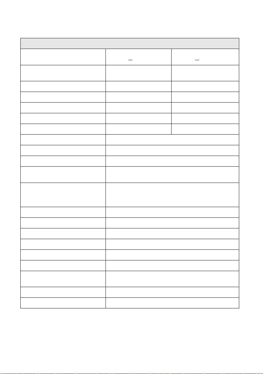
1.3 Specifications
XLN3640/XLN6024 Specifications
Output Rating
Output Voltage 0--36 V 0--60 V
Output Current 0--40 A 0--24 A
Output Power 1440 W 1440 W
Voltage ≤ 4 mV ≤ 6 mV
Current ≤ 4 mA ≤ 4 mA
Load Regulation
Voltage ≤ 8 mV ≤ 8 mV
XLN3640 XLN6024
Normal Mode Voltage
( ≥ 0.5 % of max. power)
Normal Mode Current ≤ 90 mA ≤ 70 mA
Programming Resolution
Programming 1 mV/1 mA 1.5 mV/1 mA
Readback 1 mV/1 mA 1.5 mV/1 mA
Programming Accuracy ±(% output+offset)
Voltage 0.05 %+10 mV 0.05 %+15 mV
Current 0.05 %+10 mA 0.05 %+18 mA
Readback Accuracy ±(% output+offset)
Voltage 0.05 %+10 mV 0.05 %+15 mV
Current 0.05 %+10 mA 0.05 %+18 mA
≤ 5 mVrms/≤ 60 mVpp ≤ 6 mVrms/≤ 70 mVpp
4
General
Average Command Response
Time
0.99
(Full load)
0.99
(Full load)
100--240 VAC
(Full load)
-15% -- +10%
when voltage under 95 VAC)
Power Cord, Terminal Blocks for Rapid Plug
Connector, Rackmount Kit, Manual
<50 ms <50 ms
Power Factor Correction
Remote Sense Compensation 2V 2V
Rising Time at Full Load ≤ 15 ms ≤ 20 ms
Rising Time at No Load ≤ 15 ms ≤ 20 ms
Falling Time at Full Load ≤ 15 ms ≤ 20 ms
Falling Time at No Load ≤ 1000 ms ≤ 1000 ms
Standard Interface USB
Transient Response Time ≤ 1 ms
Efficiency 80 %
AC Line Rated Input Voltage
Tolerance/Variation in
Voltage
(10% power de-rating mode
Rated Frequency 47 Hz--63 Hz
Maximum Rated Input Power 1700 VA
Temperature Ratings(O) Operation (0 °C -- 40 °C)
Temperature Ratings(S) Storage (-10 °C -- 70 °C)
Dimensions(W*H*D) 16.5 x 1.7 x 17 inch(420 x 43.6 x 432 mm)
Weight 19.8 lbs. (9 kg)
Standard Accessories
Standard Interface USB
Optional Interface LAN & GPIB
Test Equipment Depot - 800.517.8431 - 99 Washington Street Melrose, MA 02176
TestEquipmentDepot.com
5
Normal Mode Voltage
( ≥ 0.5 % of max. power)
≤ 7 mVrms/≤ 80
mVpp
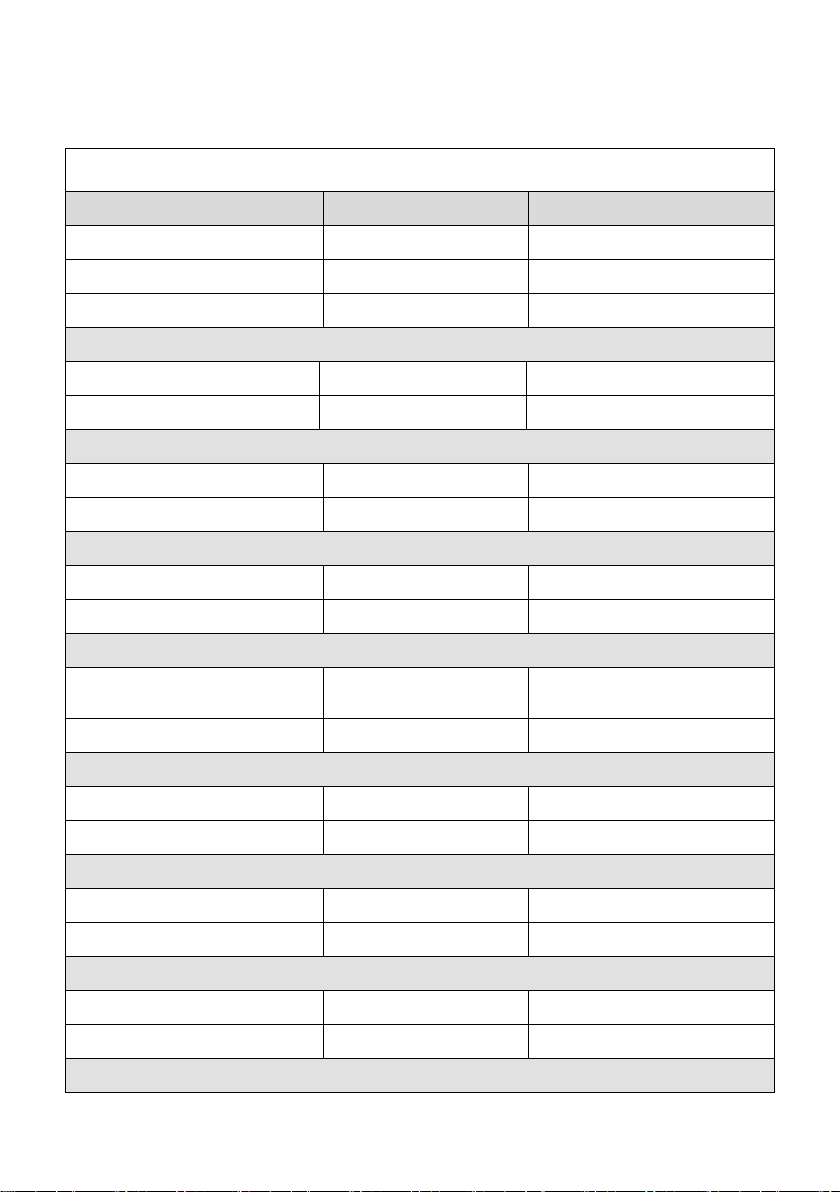
XLN8018/XLN10014 Specifications
Output Rate
Output Voltage
Output Current
XLN8018 XLN10014
0~80 V 0~100 V
0~18 A 0~14.4 A
Output Power 1440 W 1440 W
Output Protection
OVP Adjustment Range
4~85 V 5~105 V
OVP Accuracy 400 mV 500 mV
Line Regulation
Voltage ≤ 8 mV ≤ 10 mV
Current ≤ 4 mA ≤ 4 mA
Load Regulation
Voltage ≤ 10 mV ≤ 12 mV
Current ≤ 6.5 mA ≤ 6 mA
Ripple/Noise (20Hz-20MHz)
≤ 8 mVrms/≤ 80 mVpp
Normal Mode Current ≤ 50 mA ≤ 40 mA
Programming Resolution
Programming 2 mV/1 mA 2.5 mV/1 mA
Readback 2 mV/1 mA 2.5 mV/1 mA
Programming Accuracy ±(% output+offset)
Voltage 0.05 %+20 mV 0.05 %+25 mV
Current 0.05 %+7 mA 0.05 %+6 mA
Readback Accuracy ±(% output+offset)
Voltage 0.05 %+20 mV 0.05 %+25 mV
Current 0.05 %+7 mA 0.05 %+6 mA
General
6

Average Command
Response Time
Power Factor Correction
≥ 0.99
(Full load)
≥ 0.99
(Full load)
Remote Sense
100~240 VAC
( Full load )
-15 %~+10 %
when voltage under 95 VAC )
Power Cord, Terminal Blocks for Rapid Plug
Connector, Rackmount Kit, Manual
<50 ms <50 ms
Compensation
2 V 2 V
Rising Time at Full Load ≤ 25 ms ≤ 30 ms
Rising Time at No Load ≤ 25 ms ≤ 30 ms
Falling Time at Full Load ≤ 25 ms ≤ 30 ms
Falling Time at No Load ≤ 1000 ms ≤ 1000 ms
Transient Response Time ≤ 1 ms
Efficiency ≥ 80 %
AC Line Rated Input
Vo l t a g e
Tolerance/Variation in
Voltage
Rated Frequency
Maximum Rated Input
Power
( 10 % power de-rating mode
47 Hz~63 Hz
1700 VA
Temperature Ratings(O) Operation (0 °C -- 40 °C)
Temperature Ratings(S) Storage (-10 °C -- 70 °C)
Dimensions(W*H*D) 16.5 x 1.7 x 17 inch (420 x 43.6 x 432 mm)
Weight 19.8 lbs. (9 kg)
Standard Accessories
Standard Interface USB
Option Interface LAN & GPIB
Specifications and information is subject to change without notice
7

Features of models XLN3640/XLN6024/XLN8018/XLN10014:
Graphical, easy to read LCD display
Compact, high efficiency and power density
40 A output connector for quick connectivity
Convenient numerical & function keys
Store and recall 10 instrument settings
Timer (1 sec -- 100 hours)
Programmable (SCPI command only)
List mode supports up to 10 sets of program and maximum 150 steps in
total
Auxiliary 5 V/1 A output
Built-in precise voltage and current measurement
OVP, OCP, OPP and key-lock function
Series & parallel connection setup (up to 4)
Multi-unit connection mode via RS485 interface allows connection of up
to 30 power supplies.
Average measuring time per measurement is 50 ms
Standard USB interface
Optional interfaces: GPIB, LAN (order models XLN3640-GL,
XLN6024-GL, XLN8018-GL, XLN10014-GL)
8

2. Cautions Before Using
2.1 Check and Confirm Accessories before Using
After receiving this product, please verify the items received in accordance
with the ones listed below:
1. The appearance of the products is without scratch or other damages.
2. Standard parts as shown in parts list of section 8.
2.2 Operation Instructions
In order to avoid damaging the instrument due to improper operation, be
sure to read this user manual. To maintain the specified accuracy, factory
calibration should be performed annually.
2.3 Ambient Environment
1. Do not locate or operate this product in an environment with dust,
vibration, or corrosive gas and do not expose this product directly to
the sunlight. Operate it in an environment with temperature 0--40
& relative humidity 20%--80%. Pause the operation when ambient
temperature is over 40
temperatures drops to the acceptable temperature range. Operating
temperature over the above range would damage the instrument.
2. This product is equipped with one blow-out type cooling fan on the
back board and three in-take cooling fans on inner side of front board.
Provide room for good ventilation near the cooling fans and keep the
boards with a space above 10cm away from wall. To maintain good
accuracy, do not block the ventilation holes in the front and the rear
parts of the unit.
3. Although the product is designed with filters to minimize noise from
AC power source, it is recommended that it be operated in a low
power noise environment with proper earth ground. If the power
noise is unavoidable, please install a power filter.
o
C; undo the operation only after the ambient
o
C
9

2.4 Storage
The storage temperature range of this product is within -10ºC - 70ºC and
R.H. should be within 80% without moisture condensing. If not operating
this product for a long time interval, pack it with original packaging or
similar one and put it in a dry place without exposure to direct sunlight.
2.5 Power-line voltage
Rated AC power source connected to this product is within 100 V-240 V
(refer to the Product Specification for details). Before connecting to external
power source, be sure that the power switch is in OFF state and verify the
suitability of power cable (including the extension line). It should be
compatible with the rated voltage/current and should be firmly connected.
Warning :
The power cable attached with this product is certified
for safety. To change a cable or add an extension cable,
be sure that it can meet the required power ratings of
this product. Any misuse with an additional cable
would void the warranty of this product.
2.6 Fuses
This product is a switching mode power supply. The fuse installed inside is a
multi-barrier protection hardware design. It should not break under normal
operation. In case the fuse does melt, it indicates another malfunction that
causes the fuse to break. In this case, it is suggested to send this product
back to service.
Warning :
Any disassembling of the casing or changing the fuse not
performed by an authorized service technician will void
the warranty of the instrument.
10

2.7 Warm-up Time
The XLN series is fully operable upon switching the power on. However, to
reach the specified equipment accuracy, please allow the supply to warm up
for at least 30 minutes.
2.8 Power-off procedure
When the supply is not in use, be sure to turn the power switch on the panel
to the OFF position to turn off the power. After the power switch is turned to
the OFF position, the inner fans will still run for approximately 10-15
seconds to carry on the inside electric capacitor discharge process per safety
code requirement. Once the discharge process is complete, this product will
carry out the automatic shut-down process
2.9 Cautions in Operation
A. While connected in series, each power supplies should be in power-on
state and output should be "ON". In case there is any one supply that is
in power-off state or output is "OFF", the associated output current will
flow over the output bypass diode of the power-off unit and burn it out.
B. While in parallel connection mode, the output voltage of each power
supplies should be set to equal values. If the setting value of each unit is
not the same, the higher output voltage will feed back to the smaller unit
and destroy its inner parts.
C.
When the AC input voltage is lower than the full-load voltage which is
100 VAC, the supplies will activate an inner over temperature protector
and cut off the output in response to the condition. To ensure that the
entire test process can be complete smoothly, confirm that the input AC
voltage is within the specified range.
Test Equipment Depot - 800.517.8431 - 99 Washington Street Melrose, MA 02176
TestEquipmentDepot.com
11

3. Front Panel Operation
1 2 3 4 5 6 7
8
9
10
11
12 13 14
3.1 XLN3640/XLN6024/XLN8018/XLN10014 Panel
15
3.1.1 Front Panel
(1) Power switch:
Please consult the “Cautions before use” section before turning on power
switch.
(2) Display:
192x32 Graphic LCD Module
(3) Current setting
Press
to set up the current limit.
(4) Voltage setting
Press
to set up the output voltage.
:
:
(5) Dot/Local :
This button is applied as a decimal point. Or push this button after
entering REMOTE online state to revert back to LOCAL mode
(unit-operation mode). Or press this button to release after entering
LOCK mode.
12

(6) ESC/CLR :
In “Menu Setting” status, use this “Down” key to move cursor
Under Memory Setting status, use this key to store setting to
the selected memory set.
Setting” status, use this “Down” key to move cursor
Under Memory Setting status, use this key to recall setting
from the selected memory set.
=
36
. FF
5
1
.
=
.
.
Press this button to clean up numerical setting or jump to the previous
screen.
(7) Numerical keys
They are used to directly input the voltage or current value or choose the
setting option in Menu screen.
(8) Down/Right/Store
This key is a multi-function key for the following three functions:
Down:
to the next item.
Right: Under “Output” status, use this key to move cursor right.
Store:
(9) Up/Left/Recall :
This key is a multi-function key for the following three functions:
Up:
Left: Under “Output” status, use this key to move cursor left.
Recall:
In “Menu
to the up item.
- :
:
(10) Display :
In “Menu Setting”, press
the display to show voltage and current or power and load resistance as
shown below:
to return to main screen or toggle
13

.
1= .
5
FF
.
3=6
.
(11) Output :
=
FF
.
.
Control the On/Off of the output power.
(12) The rotary knob:
Use this knob to adjust voltage or current (press
cursor display first). This is adjustable when output is ON.
first to let
(13) Enter
This key is the confirmation key of current or voltage setting value; or
press
mode) or current (at CC mode).
(14) Mem
Press this key to enter access the storage memory. Users can then use the
numerical key or knob to select the target memory set to save or recall
the configuration by pressing the STORE or RECALL key. Ten sets are
available in selection.
(15) Menu :
Use this key to enter system parameter settings. There are eight (8) major
items under operation. Users may press
through the menu list or the numerical keys to enter the corresponding
item number in the menu list.
:
under output status to dynamically adjust voltage (at CV
:
,
to scroll
14

L=
= 1
T
=L
FF
1 . SYSTEM SETTING
2 . OUTPUT SETTING
3 . PROTECTION
4
.
F
5
.
6
.
L T T F
LL L
T
7 . TIMER CONTROL
8 . CALIBRATION
9 . CHAIN SETTING
1. SYSTEM SETTING:
Pressing
following “SYSTEM SETTING” menu.
REMOTE CONTROL:
key in the first page of Menu Setting will enter the
Choose the remote interface
(USB/GPIB/ETHERNET)
*GPIB and ETHERNET available only
with on models with “-GL” suffix
*USB control requires installing USB
drivers first. Download USB driver
from
www.bkprecision.com
*USB interface is a virtual COM port. T he settings are:
Baudrate : 57600 bps
15

Data bit : 8
1
.
= .
5
F
F
3
.
= .
6
control to voltage
istance
=
5
F
52=
= F
552. 552. 552
.
F
L
a
If you are not sure of the IP settings, consult
able KEY
are locked.
Parity check : none
Stop bit : 1
*When entering the Remote mode, screen will present RMT indicator as
shown in the following picture.
GPIB ADDRESS:
EXTERN CONTROL:
Set up GPIB ADDRESS (1-30)
Set up the external
control (VOLT 0-10 V or 0-5 V), res
control (RES 0-5K) or off (OFF).
IP CONFIG:
IP ADDRESS:
KEY LOCK:
*Simultaneously pressing both and keys in the main
screen can also lock keys.
STATIC : User can input IP address
If IP CONFIG is set to STATIC, users can enter
static IP address here.
Note:
your network administrator.
While exiting the setting screen after en
LOCK, all keys except the key
Only this key can disable KEY LOCK.
*While entering KEY LOCK state, screen will present LCK indicator in
the bottom right corner.
16

L
=
F
L
L
=
=
L
L
L
Set the backlight of the LCD to Always
default
.
FF=
F
=
,
=.F
=,FF
5
=
(on the rear
of the supply
If
the
use the last setting before it
a prompt will ask for setting
Once set, these values are then used the next
f the
9
number keys to recall the voltage and current
BEEP:
LCD BACKLIT:
RECALL DEFAULT:
Ext 5V OUTPUT:
POWER ON STATE:
Turns the Buzzer ON/OFF
ON or OFF after 1/5/10/30 minutes
Restores the manufacturer
settings
Turns the extra 5V power output
panel) ON/OFF.
Users can set the output state
when powered on. When OFF is selected, the
XLN series will do nothing after power on.
LAST is selected, then at power on
supply will
turned off previously. If USER (user defined)
is selected,
output voltage, current, and output state.
time the supply is powered on.
HOT KEY:
HOT KEY = OFF
Set the HOT KEY function ON/OFF. I
HOT KEY function is ON, user can use 0 –
17

setting values stored inside internal memory.
*If entering the HOT KEY mode, screen will indicate HOT symbol as
6
.
=
3
.
4
.
=
.
F
F
VOLT LIMIT:
Upper limit of the output voltage setting
CURR LIMIT:
Upper limit of the output current setting
VOLT SLEW RATE:
Voltage ascending/descending slope
(XLN3640: 0.01 - 2.4V/ms)
(XLN 6024:0.01 - 3V/ms)
(XLN 8018:0.01 - 3.2V/ms
(XLN 10014:0.01 - 3.3V/ms)
shown in the following illustration.
2. OUTPUT SETTING:
Press
SETTING menu.
in the first page of Menu Setting to enter OUTPUT
VOLT LIMIT MAX = 60.500 V
CURR LIMIT MAX = 24.500 A
VOLT LIMIT MIN = 0.000 V
CURR LIMIT MIN = 0.010 A
VOLT SLEW RATE = 3.0000 V/mS
CURR SLEW RATE = 1.2000 A/mS
CONNECTOR DROP = DISABLE
EXT FULL VOLT = 10 V
18
CURR SLEW RATE:
Current ascending/descending slope
(XLN 3640:0.01 - 2.5A/ms)
(XLN 6024:0.01 - 1.2A/ms)
(XLN 8018:0.01 - 0.72A/ms
(XLN 10014:0.01 - 0.48A/ms)
control.
overvoltage protection
point.
overcurrent protection
set up the overcurrent protecting
protection
point.
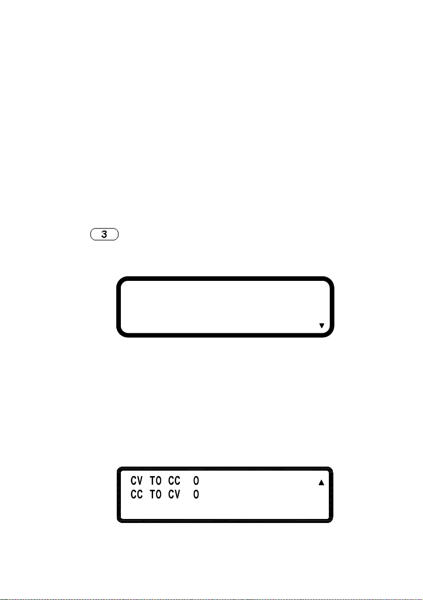
CV TO CC:
Enable/disable the protection of the change
CONNECTOR DROP:
EXT FULL VOLT:
3. PROTECTION SETTING (PROTECTION)
Press
PROTECTION menu.
key in the first screen of “Menu Setting” to enter
Turns on/off the connector drop calibration
function
External voltage control full-scale setting.
Select between 10 V or 5 V for full-scale
OVP = OFF SET = 38.000 V
OCP = OFF SET = 42.000 A
OPP = OFF SET = 1440.000 W
OVP:turns on/off the
OCP:turns on/off the
OPP:turns on/off the overpower
SET: set up the overvoltage protecting
SET:
point.
SET: set up the overpower protecting
FF
=
FF
=
19
from CV to CC mode
from CC to CV mode
L
T
L
T
FF
=
=
T
series or parallel operation
for the detailed setting
procedure of MASTER/SLAVE mode.
F
463L
L
:
1
31
.
L
CC TO CV:
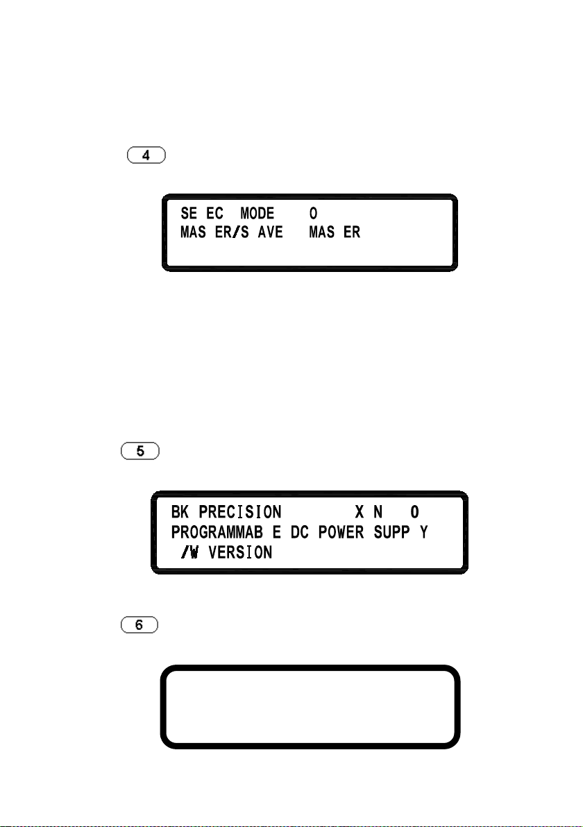
4. SERIES/PARALLEL SETTING
Press
SERIES/PARALLEL menu.
SELECT MODE: Choose
MASTER/SLAVE:
5. INFORMATION
Press
INFORMATION screen.
in the second screen of “Menu Setting” to enter
Enable/disable the protection of the change
in the second screen of Menu Setting to enter
mode.
Refer to “Series/Parallel Setting”
section
6. SPECIAL TEST FUNCTION
Press
TEST FUNCTION menu.
in the second screen of “Menu Setting” to enter SPECIAL
1. CURRENT COUNTER TEST
2. PROGRAM MODE
3. MEASURE AVERAGE
20
6.1 CURRENT COUNTER TEST: Press to enter the
= 1 . = .
:
.
FF
= 1 .
:
CURRENT COUNTER TEST screen.
Refer to “Current Counting” section for the detailed setting procedure.
6.2 PROGRAM MODE: Press
menu.
Before running the program, user needs to input the programmed
values through the USB or GPIB interface into the power supplies.
Users may save up to 10 programs (program number 1 through 10)
inside the memory and recall them in this Program Mode screen by
selecting the program number and then pressing
the program.
6.3 MEASURE AVERAGE: Press
AVERAGE page.
AVERAGE TIME = 2
AVERAGE TIME:
to enter the PROGRAM MODE
1=
Set the average measure time.
to enter the MEASURE
to execute
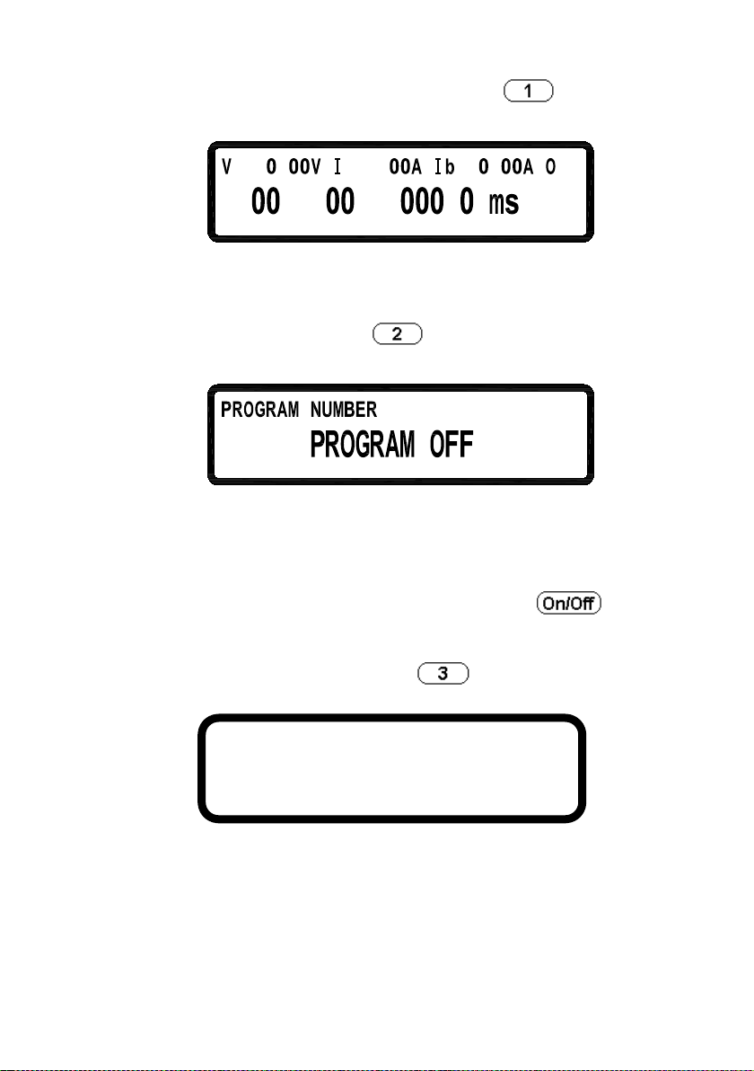
7. TIMER CONTROL
21
Press
CONTROL screen.
in the third page of Menu Setting to enter TIMER
FF
=
=
r
ni ec
TIMER:
TIME:
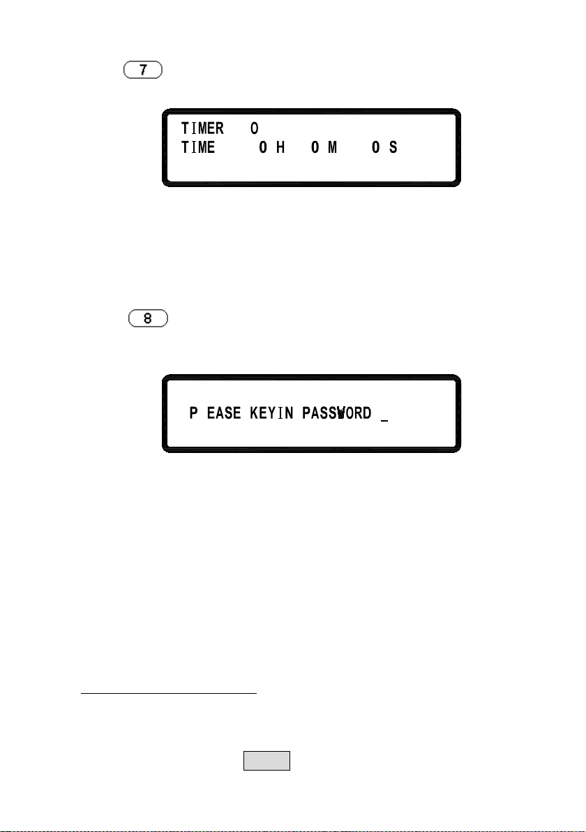
8. CALIBRATION
Press
CALIBRATION menu. Users must enter the password to access
calibration mode.
in the third page of “Menu Setting” to enter
L
8.1 Equipment Requirements
1. 5 ½ Digital Volt meter.
2. Shunt for current calibration (100 A/ 10 m Ω)
Turn on/off TIMER function.
Set up OUTPUT ON time (Max:999Hr 59Min
59Sec)
:
8.2 Calibration Procedure
VOLTAGE CALIBRATION
A. Connect power supply output terminal to DVM (as shown in
Figure 1 below). Turn on the supply. Once the unit enters the
main page, press MENU and select “8. Calibration” and key in
22
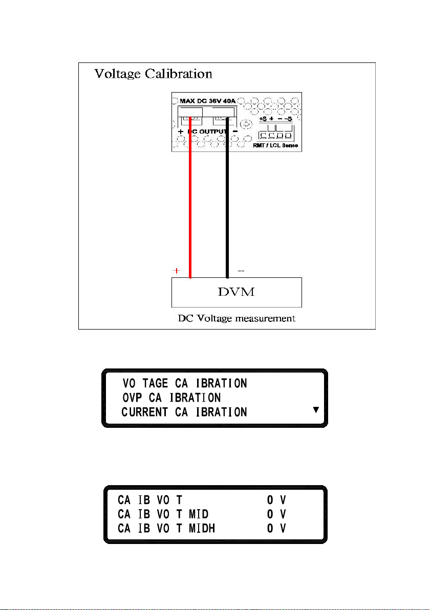
password “13579” to enter the following calibration menu screen:
L
1
.
3
2
.
.
L
L
L
Figure 1
B. Press “1” to access Voltage Calibration Procedure.
C.
L
L
L
L
o
L
1=L
2 4
=
23
468.1=L
2
455
.
5
11L
 Loading...