

Page 1

Model 878B, 879B
Dual Display LCR
INSTRUCTION MANUAL
METER
Visit us at www.TestEquipmentDepot.com
99 Washington Street
Melrose, MA 02176
Phone 781-665-1400
Toll Free 1-800-517-8431
Page 2

Page 3

Safety Summary
The following safety precautions apply to both
operating and maintenance personnel and
must be observed during all phases of
operation, service, and repair of this
instrument.
DO NOT OPERATE IN AN EXPLOSIVE
ATMOSPHERE
Do not operate the instrument in the presence
of flammable gases or fumes. Operation of
any electrical instrument in such an
environment constitutes a definite safety
hazard.
KEEP AWAY FROM LIVE CIRCUITS
Instrument covers must not be removed by
operating personnel. Component
replacement and internal adjustments must be
made by qualified maintenance personnel.
DO NOT SUBSTITUTE PARTS OR MODIFY
THE INSTRUMENT
Do not install substitute parts or perform any
unauthorized modifications to this instrument.
Return the instrument to B&K Precisi on for
1
Page 4

service and repair to ensure that safety
features are maintained.
WARNINGS AND CAUTIONS
WARNING and CAUTION statements, such
as the following examples, denote a hazard
and appear throughout this manual. Follow all
instructions contained in these statements.
A WARNING statement calls attention to an
operating procedure, practice, or condition,
which, if not followed correctly, could result in
injury or death to personnel.
A CAUTION statement calls attention to an
operating procedure, practice, or condition,
which, if not followed correctly, could result in
damage to or destruction of part or all of the
product.
Safety Guidelines
To ensure that you use this device safely,
follow the safety guidelines listed below:
2
Page 5

This meter is for indoor use, altitude up to
2,000 m.
The warnings and precautions should be
read and well understood before the
instrument is used.
When measuring in-circuit components, first
de-energize the circuits before connecting to
the test leads.
Discharge capacitor before testing.
The meter is safety-certified in compliance
with EN61010 (IEC 1010-1) Installation
Category II (CAT. II) 50 V, Pollution Degree
2 environment.
Use the meter only as specified in this
manual. Otherwise, the protection provided
by the meter may be impaired.
The power for the meter is supplied with a
single standard 9V battery. But also a line
operation is possible using a 12V AC to DC
adaptor. If a power adaptor is selected,
please be sure to use fulfilled the safety
requirements of a relevant IEC standard.
3
Page 6

outside is negative (-)
Safety Symbols
This symbol is a warning and
indicates that the user should refer to
the operating instructions located in
the manual.
DC Current
Indicates inside pin is positive (+),
Compliance Statements
Disposal of Old Electrical & Electronic Equipment
(Applicable in the European
Union and other European countries with separate
collection systems)
4
Page 7
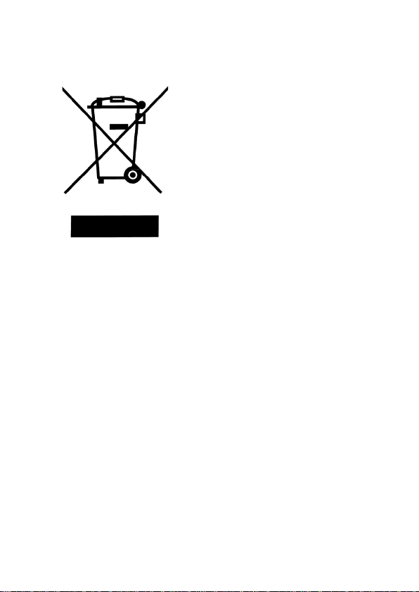
This product is subject
Council of the European
equipment (WEEE) , and
to Directive 2002/96/EC
of the European
Parliament and the
Union on waste
electrical and electronic
in jurisdictions
adopting that Directive,
is marked as being put
on the market after
August 13, 2005, and
should not be disposed
of as unsorted
municipal waste. Please
utilize your local WEEE
collection
facilities in the
disposition of this
product and otherwise
observe all applicable
requirements.
5
Page 8

Storage Humidity
0 – 80% R.H.
Storage Environment
-20 °C to +50 °C
Pollution degree
Pollution degree 2
Environmental Con diti ons
Operating Environment
0 °C to 40 °C
6
Page 9

TABLE OF CONTENTS
Safety Summar y ........................................................ 1
Safety Guidelines ...................................................... 2
Compliance Statements ........................................... 4
INTRODUCTION ....................................................... 10
PACKAGE CONTENTS ........................................... 11
FRONT PANEL OVERVIEW .................................... 12
Front Panel Display Descriptions .................................. 13
Front Panel Buttons ...................................................... 15
LCD DISPLAY OVERVIEW ...................................... 17
LCD Display Descriptions ............................................. 17
Special Display Indicators ............................................. 19
POWERING INSTRUMENT ..................................... 20
Installing Battery ........................................................... 20
Connecting External Power Source .............................. 22
Low Battery Indication .................................................. 24
Backlit Display (model 879B only) ................................ 25
OPERATION INSTRUCTIONS ................................. 27
Data Hold ...................................................................... 27
Static Recording ........................................................... 27
7
Page 10

L/C/R/Z Select Mode .................................................... 30
D/Q/θ/ESR Select Mode ............................................... 31
Test Frequency ............................................................. 31
Relative Mode ............................................................... 50
Tolerance ...................................................................... 52
Utility Menu ................................................................... 56
Parallel and Series Measurement Mode ....................... 67
Calibration..................................................................... 85
USB .............................................................................. 90
Automatic Fuse Detection ............................................. 91
QUICK START GUIDE ............................................. 93
CAUTION...................................................................... 93
Inductance Measurement ............................................. 94
Capacitance Measurement ........................................... 96
Resistance Measurement ............................................. 98
Impedance Measurement (Model 879B only) ............... 99
REMOTE COMMUNICATION ................................ 101
Connecting Instrument to PC ...................................... 101
USB (Virtual COM) Configuration ............................... 103
USB Operation ............................................................ 103
Command Protocols ................................................... 105
8
Page 11

SUPPLEMENTAL INFORMATION ........................ 118
Selecting Test Frequency ........................................... 118
Selecting Series or Parallel Mode ............................... 120
Accuracy Discrepancies.............................................. 121
Guard Terminal ........................................................... 123
SPECIFICATIONS .................................................. 125
General Specifications ................................................ 126
Accuracy Specifications .............................................. 127
MAINTENANCE ...................................................... 133
Service ........................................................................ 133
Cleaning...................................................................... 133
SERVICE INFORMATION ...................................... 135
LIMITED WARRANTY ............................................ 136
9
Page 12

INTRODUCTION
B&K Precision’s 878B and 879B 40,000-count L/C/R
hand-held meter is designed ideally for measuring
inductance, capacitance and resistance components.
Simple to operate, the instrument not only takes
absolute parallel m ode m easur em ents, but a lso series
mode measurement. The meter provides direct and
accurate measurements with selectable testing
frequencies.
Front panel push buttons maximize the convenience
of function and feature selection such as data hold,
maximum, minimum and average record mode,
relative mode, tolerance s orting mode, fr equency and
L/C/R selection.
The test data can be transferred to PC through a Mini
USB connection, great for applications that require
data logging
A tilt stand provides position flexibility for viewing and
operating the meter. The over-molding rubber case
protects the meter for better durability. Additionally,
top rubber visor molding above the screen is designed
to prevent scratches on the display when meter is
positioned upside down.
10
Page 13

A single 9V battery or the included DC 12V power
adaptor (model 879B only) can be used to power the
meter. This gives user flexibility for portable or benchtop use.
PACKAGE CONTENTS
Each 878B and 879B LCR meters are shipped with
the following contents.
• 878B or 879B LCR meter
• Instruction Manual
• Mini USB Interface Cable
• Red & Black Banana to Alligator Test Leads
• 9V Batt ery
• *AC Ad apter (m odel 879 B only)
*This can be purchased as an optional accessory for
model 878B.
Please locate them from the original packaging to
ensure nothing is missing. If in the case that an item
is missing, please contact B&K Precision immediately.
11
Page 14
+ -
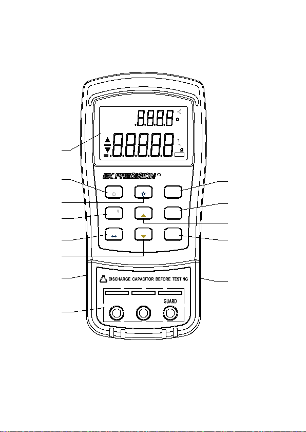
FRONT PANEL OVERVIEW
LCR Meter
REL
LCR
Z
ESR
MAX
MIN
AVG
¦ÈQ
DH
AUTO
TOL
D
1%5%10%20%
OFF
@
1
2
3
POWER
D/Q/
P
/ESR
FREQ
S
4
5
L/C/R/Z
USB
TOL
879B
deg
%
kHz
PAL
SER
n
¦ÌH
n
p F
¦Ì
Mk
RMT
R
HOLD
REC
UTIL
REL
CAL
7
8
9
10
6
13
!
11
12
Figure 1 - Front Panel Display (model 879B shown)
12
Page 15

Front Panel Display Descriptions
1. LCD Display
2. Power ON/OFF Button
3. USB Communication / *Back light button
4. Secondary Display mode (for dissipation
factor(D), quality factor (Q), *phase angle (θ),
*equivalent series resistance (ESR)
measurement) selection button
5. Primary Display mode (for inductance,
capacitance, resistance, and *impedance
measurements) / Parallel or Series
measurement method selection button
6. Tolerance mode / Utility down arrow selection
button
7. Hold Display mode / Record mode selection
button
8. Utility menu button
9. Test Frequency / Utility up arrow select ion
button
10. Relative mode / Calibration mode selection
button
11. 12V DC adapter input (use with an external
power adapter (rated 12VDC, 150mA, 4mm
power plug))
Note: Use with included power adapter only.
Use with improper power adapters may
damage instrument.
13
Page 16

WARNING: Before connecting an external
power adapter, please check the battery
compartment in the rear side of the unit. If
a battery is installed, be sure that the
polarity matches the (+) and (-) labels as
indicated inside the battery compartment.
If it is not installed correctly , please
remove the battery and install it with
correct matching polarity as indicated in
the compartment. See “Installing Battery
section for details. DO NOT, at any time,
connect an external power adapter when a
battery is installed incorrectly. Doing so
will damage the instrument and void its
warranty.
Input sockets (banana jack inputs) and terminals for
positive, negative, and guard (see “Guard Terminal” in
“
”
14
Page 17

12. SUPPLEMENTAL INFORMATION” section for
details)
13. Standard mini USB port (for remote
controllability)
For model 879B only. Not included on model 878B.
*
Front Panel Buttons
All front panel buttons have specific colored labels on
them. They are all marked in white, blue, or yellow
color. Each color has a specific representation, as
described below:
White – With the exception of the
button, all white colored labels
represent the primary function of that
button; meaning that function will be
set or configured upon pressing it.
Blue – Some of the buttons have a blue label
underneath a white label. This means
the function indicated by the blue
label will be set or configured if that
button is pressed and hold down for 2
seconds.
Yellow – There are total of 3 buttons with
yellow labels. They are
15
Page 18

exclusively for use when entering
UTIL menu only. See “Utility Menu”
section for details.
. These functions are
16
Page 19

LCR
REL
ESR
MAX
AVG
MIN
¦ÈQ
AUTO
D
1%5%10%20%
deg
kHz
PAL
SER
¦ÌH
p F
¦Ì
RMT
Mk
TOL
DH
n
n
@
OFF
Z
1
2 5 9 10
12
14
16
202126
27
28
83
232425
4
15
11
13
6 7
22
17
18
19
%
29
LCD DISPLAY OVERVIEW
Figure 2 - LCD Indicator Display
LCD Display Descriptions
1. LCRZ – Primary display funct ion indic ator (*Z
2. MAX – Maximum reading indicator
3. AVG – Average reading indicator
4. MIN – Minimum reading indicator
5. REL – Relative mode indicator
display)
17
Page 20
6. Θ – *Phase angle indicator f or sec ondary
display
7. Q – Quality factor indicator
8. ESR – *Equivalent series resistance indicator
9. – Secondary display
10. – Beeper tone indicator for tolerance
mode
11. deg – *Phase angle degree indicator
12. Ω – *ESR(ohm) units indicator
13. % - Tolerance percentage indicator
14. kHz – Frequency units indicator
15. PAL – Parallel mode indicator
16. SER – Series mode indicator
17. – Inductance units (Henry) indicator
18. – Capacitance units (Farad) indicator
19. MkΩ – Resistance units (Ohm) indicator
20. RMT – Remote mode indicator
21. – Primary display
22. D – Dissipation factor indicator
23. DH – Data hold indicator
24. AUTO – Auto-ranging indicator
25. TOL – Tolerance mode indicator
26.
27. @OFF – Auto power-off indicator
28. 1%5%10%20% - Tolerance sorting
– Low battery indicator
percentage indicator
18
Page 21

29. MAX AVG MIN – Recording mode indicators
For model 879B only. Not included on model 878B.
*
Special Display Indicators
Indicates short connectors
Indicates open connectors
Error indication
Indicates calibration mode
Indicates damaged or open fuse
AD converter error
AD converter error
19
Page 22

POWERING INSTRUMENT
Before beginning to operate the instrument, a power
source is necessary for it to turn on. There are two
methods to power the instrument: Battery and
external source.
Installing Battery
The 878B and 879B LCR meters can use a battery to
provide power to the instrument so that it can be
portable.
The meters use a standard 9V size battery (or
NEDA 1604, JIS006P, IEC6F22 carbon-zinc or
alkaline battery).
To install the battery:
1. Place the meter upside down. Open up the
back-flip stand, and locate the screw that
tightens the battery compartment cover as
indicated in Figure 3. Use a screwdriver to
unscrew and remove the cover.
20
Page 23

Figure 3 - Back Cover
2. Insert 9V battery into compartment. Note the
positive (+) and negative (-) terminals as
indicated inside the battery compartment (See
Figure 4). Be sure to insert the batter y with
matching polarity.
21
Page 24

Figure 4 - Battery Compartment
3. Place the battery compartment cover piece by
sliding it into the top slid first. Place screw at
the bottom of the cover piece and tighten
down with a screw driver.
4. Push and hold down the button for 2
seconds to turn on the instrument.
Connecting External Power Source
The 878B and 879B can also be powered using an
external AC adapter. The model 879B comes with
this adapter included in the pac kage, while it is
optional
for model 878B.
22
Page 25

For external power, use AC adapter rate d for
output 12VDC, 150mA, with a standard 4mm
connector only.
WARNING: Use of incorrect adapters may damage
the instrument. Please use B&K Precision’s adapter
only.
To connect the adapter, do the following:
1. If a battery is installed, please check the
battery compartment again that the polarity of
the battery matches the polarity as indicated
by the labels inside the compartment. If it is
not, please remove and insert the battery with
matching polarity. If a battery is not installed,
continue to the next step.
WARNING: DO NOT, at any time, connect
an external power adapter when a battery
is installed incorrectly (reverse polarity or
non-matching polarity to indicator of
battery compartment). Doing so will
damage the instrument and void its
warranty.
2. Connect the AC adapter connector into the
right side panel of the instrument. See Figure
5 below.
23
Page 26
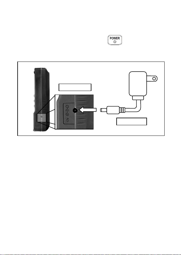
AC Adapter
Figure 5 - Connecting AC Adapter to Meter
3. Now, connect the AC Adapter socket into an
electrical outlet.
4. Push and hold down the button for 2
seconds to turn on the instrument.
12VDC Input
Note: The meter can be operated with a battery
installed while an AC adapter is plugged in at the
same time (As long as the battery is inserted properly
with correct polarity). In this event, the meter will
automatically switch to consume power from the AC
adapter instead of the battery to preserve battery life.
Low Battery Indication
The LCR meter has a low battery indicator to notify
the user when to replace battery. When the display
24
Page 27

starts flashing the indicator, the battery voltage
is below normal working voltage. In this case,
accuracy of the meter will also decrease. It is
recommended that the battery be replaced as soon as
possible before continuing operation. See “Installing
Battery” for instructions.
Backlit Display (model 879B only)
Model 879B LCR meter has a backlit display that
allows you to see the LCD display in dark conditions.
To turn on the back light, press and hold down
button for 2 seconds. Back light will turn on and
brighten the LCD display.
To turn off the back light at any time, press and hold
down button for 2 seconds again. Back light
will turn off and return to normal display.
When Using Battery Power
When the meter is powered using 9V battery, the back
light display will turn on upon holding down the
button for 2 seconds. It will stay at maximum
25
Page 28

brightness for 15 seconds. After another 15 seconds
(30 seconds total from the time of turning on), the
back light will automatically turn off to conserve
battery power.
When Using External Power
When the meter is powered using an external AC
adapter, the back light display will turn on upon
holding down the button for 2 seconds. It will
stay at maximum brightness continuously until the
user presses and holds down the button for 2
seconds again.
Note: If a battery is installed while using an AC
adapter simultaneously, un plu ggi ng the AC ada pter
will automatically turn off the back light after it has
been lit for 30 seconds.
26
Page 29

OPERATION INSTRUCTIONS
Data Hold
The data hold function allows the user to freeze the display
when pressed, holding the measured value until data hold is
turned off.
Turn On Data Hold
To use data hold, press the button once. The “DH”
indicator will display on the screen when data hold is active.
Turn Off Data Hold
To disable the data hold, press again. The “DH”
indicator will disappear on the screen, and meter will remain
in normal operation mode.
Note: Changing the primary function, secondary function,
or test frequency will automatically turn off the data hold.
Static Recording
This mode is used for recording maximum, minim um, and
average values. It is often useful for testing the range of
values in which a component is expected to fall within upon
measurement.
27
Page 30
Enable Static Recording
Press and hold down the button for two seconds to
enter the static recording mode. The display should indicate
“MAX AVG MIN” simultaneously. This indicates the meter is
in static recording mode and recording is performed
immediately.
Using Static Recording
There are four different modes that can be selected in
static recording. They are indicated by the
descriptions below. These modes can be changed
with each button press. Per each press of the
button, the modes will change and repeat in
the following order:
Recording Mode Maximum Mode Minimum
Mode Average Mode
Recording Mode
This is the default mode when first enabling static
recording. In this mode, the screen will display “MAX
AVG MIN” indicator. At this point, the meter will start
making recordings based on measured values from
28
Page 31

the input sockets or terminals. As recording is
performed, maximum, minimum, and average values
will be stored after a brief moment. A beep tone will
sound once a recording has been stored.
Note: Subsequent beep tones may occur in this mode if
there are new values that are recorded. For example, if a
new maximum is detected, it will beep once again to indicate
that the new value has been stored. Any previously stored
values will be overwritten with the new recorded values.
Maximum Mode
In this mode, the “MAX” indicator will be shown on display.
This indicates that the value in the primary display
represents the recorded maximum value.
Minimum Mode
In this mode, the “MIN” indicator will be shown on display.
This indicates that the value in the primary display
represents the recorded minimum value.
Average Mode
In this mode, the “AVG” indicator will be shown on display.
This indicates that the value in the primary display
represents the recorded average value. This average value
is obtained by taking the maximum and minimum recorded
values and taking the average of the two values.
29
Page 32

Disable Static Recording
To exit this mode, press and hold the button for two
seconds. The “MAX AVG MIN”, “MAX”, “MIN”, or “AVG”
indicator will disappear on screen.
Note: Changing the primary function, secondary function,
or test frequency will automatically turn off static recording.
L/C/R/Z Select Mode
The primary display of the LCR meter is used to
indicate measured values under four different modes
(three modes for model 878B, which excludes Z
(impedance) measureme nt s ). These modes are:
L (inductance), C (capacitance), R (resistance), and Z
(impedance).
To change between these four primary modes of
measurement, press the (or for model
878B) button. The modes will change and repeat
upon each button press. On the screen, the indicators
“L”, “C”, “R”, or “Z” (model 879B only) will be
displayed to indicate which mode the meter is in.
30
Page 33

D/Q/θ/ESR Select Mode
The secondary display of the LCR meter is used to
indicate measured values for four various parameters
(two for model 878B, which excludes θ and ESR
measurement mode), which provide additional
information of the component being tested and is
supplementary to the primary mode measurements.
These modes are: D (Dissipation factor), Q (Quality
factor), θ (Phase angle), and ESR (Equivalent series
resistance).
To change between these measurement parameters,
press the (or for model 878B) button.
The parameters for measurement will change and
repeat upon each button press. On the screen, the
indicators “D”, “Q”, “θ” (model 879B only), or “ESR”
(model 879B only) will be dis played to indicate which
secondary mode the meter is in.
Test Frequency
The 879B and 878B LCR meters use an AC signal to test
and measure components at the input sockets or
terminals. With this measurement method, a test
frequency must be selected. The test frequency can
affect the accuracy of the results depending on what
frequency is selected and what type and value of a
31
Page 34

component is being measured or tested. For details on
selecting the optimal test frequency for measurement,
refer to the “
32
Page 35

REMOTE COMMUNICATION
The meter has the capability to communicate with a
PC over the mini USB interface. Upon installation of a
USB driver, the PC can control the instrument over
virtual COM (RS-232). The mini USB communication
interface of the meter is designed in full duplex and
has a 64-byte input and output buffer, making it
reliable and efficient for data transmission.
Connecting Instrument to PC
Follow the below procedures for connection setup.
1. Download the USB drivers from
www.bkprecision.com .
2. With the included mini USB cable, connect the
mini USB end to the LCR meter and the other
end to an available USB port on the PC (see
Figure 14).
3. When Windows recognize the USB
connection, do not follow the default Windows
driver installation wizard. Simply run the
setup file from the downloaded USB drivers
and follow the prompt to install drivers.
4. When completed, the computer will recognize
the instrument as a USB (virtual COM) device,
meaning it will be detected as a serial COM
33
Page 36
port. Windows will automaticall y assign a
COM port to the instrument. Please verify
which COM port Windows has assigned by
going into “Device Manager”.
Figure 14 - USB Connection
34
Page 37

USB (Virtual COM) Configuration
The USB will be recognized as a virtual COM on the
PC, thus serial port settings must be configured
properly for remote communication to be successful.
Below are the settings used by the 878B and 879B
meters.
• Baudrate: 9600
• Dat a bits: 8
• Parity: None
• Stop bits: 1
• Flow Control: None
USB Operation
There are two modes that describe the operation of
the meter when it is setup for remote communication.
They are remote mode and auto fetching mode.
Remote Mode
Upon connecting to the instrument, sending any
commands listed in the “Command Protocols” section
will automatically set the LCR meter into remote
mode. In remote mode, the LCD display will show the
RMT indicator. When this is shown, all front panel
35
Page 38

buttons will be disabled, except for the (or
for model 878B) button.
To exit remote mode and go back to local mode,
press the (or for model 878B) button
once. The
display. Pushing the same button once more will put
the meter into auto fetching mode, which is described
in the next section.
Auto Fetching Mode
When connected to a PC, the meter can be
configured to auto-fetching mode. This means, the
meter will continuously fetch data to the PC after
every measurement cycle is completed. It fetches
data from measured readings of primary display and
secondary display, as well as tolerance compared
results. This mode is useful when doing quick data
logging using PC.
RMT indicator will disappear on the LCD
36
Page 39

Enable/Disable Auto Fetching
To toggle between enabling and disabling auto
fetching, press the (or for model
878B) button. When enabled, data will be fetched
constantly after every measurement cycle is
completed. When disabled, no fetched data will be
available.
Note: Alternatively, auto fetching mode can be
disabled when a remote command is sent to the
instrument, turning it back into remote mode. In this
event, the
display, and auto fetching will be disabled
automatically. To re-enabled auto fetching again in
this state, first press the (or for model
878B) button once to exit out of remote mode and
return to local mode. Then, press the button once
more to have it set to auto fetching mode again.
RMT indicator will appear on the LCD
Command Protocols
Overview of Command Type and Format
All commands are entered in either the upper case or
the lower case. There are two types of the meter
programming commands: IEEE 488 common
37
Page 40

commands and Standard Commands for
Programmable Instruments (SCPI). Some commands
are device-specific to the meter. They are not included
in the version 1999.0 of the SCPI standard. However,
these commands are designed with the SCPI format
in mind and they follow the syntax rules of the
standard.
Common Command Format
The IEEE 488 standard defines the common
commands as commands that perform functions like
reset and system query. Common commands usually
come with the asterisk “*” character, and may include
parameters. Some examples of Common command
like: *IDN?, *GTL, *LLO.
SCPI Command Format and Query Format
The SCPI commands control instrument
functions. A subsystem command has a hierarchical
structure that usually consists of a top-level (or root)
keyword, one or more lower level keywords, and
parameters. The following example shows a
command and its associated query:
A. FUNCtion:impa L
Select L as primary parameter
B. FUNCtion:impa?
Return primar y parameter
38
Page 41

function is a root level keyword with the second level
keyword, impa, and L is the command parameter. The
query command ends with a question mark “?”.
Note: SCPI stems from IEEE488.1 and IEEE 488.2.
Although the IEEE 488.2 standard addressed some
instrument measurements , it princ ip al ly dealt with
common commands and syntax or data formats.
Please refer to the IEEE488.2 and SCPI reference
manual for more information.
Termination Character
A terminator is a character sent by a host, which
identifies the end of a command string. A valid
terminator consists of two-byte data:
<CR> (Carriage Return, ASC(&H0D)) or <LF> (Line
Feed, ASC(&H0A) ) o r <CR><LF>
Responding Message
Returned result
After the meter executes a query command, the return
of the result will be in the following format:
<Result> + <CR> <LF>
For example, in auto fetching mode, the meter will
send the measured data automatically when the
39
Page 42

Data Type
Explanation
Example
<NR1>
An integer
+800,-200,100,-50
This numeric
point
This representation
exponent
A parameter for
or “1” for Boolean
measurement cycle is completed. The format of the
printed data will be shown as the following:
<Primary measured data, Secondly measured
data, Tolerance Result > + <CR> <LF>
Data Types
Returned message is an ASCII string from the meter
responding to a query. A query is a command
accompanied a “?” mark. Table 4 below explains the
different data types.
Table 4 - Data Type of Responded Message s
<NR2>
<NR3>
<Boolean>
representation has
an explicit radix
has an explicit
radix point and an
Boolean setting.
Always return “0”
40
+1.56,-0.001,10.5
+2.345678E+04
-1.345678E-01
ON or OFF
Page 43

query command
short literal form
Text Symbol
Meaning
[ ]
Option; can be omitted
|
Exclusive OR
< >
Defined element
( )
Comment
?
Question mark
Separated two command
keywords
A string is used as
<Literal>
command
parameters with
HOLD
SCPI Commands
This section described all the SCPI commands
supported by the meter. The meter can accept both
upper case and lower case commands.
Table 5 - SCPI Symbol Conventions
:
41
Page 44

Description: Queries the instrument ID.
version>, <serial number>
Set 100Hz frequency
Description: Query the measurement frequency
only)
*IDN?
Response: <instrument model>, <firmware
*LLO
Local Lockout. This means that all front panel
buttons, including the "USB" key is not available.
*GTL
Go to local.
Puts the meter into the local state,
clearing the remote state and front panel lockout.
FREQuency Subsystem
FREQuency <value>
Description: Set measurement frequency
Parameters: Parameters are 100, 120, 1000,
10000 (879B only) or
100hz,120hz,1khz,10khz (879B
only)
Example: FREQuenc y 100hz
FREQuency?
Response: 100hz, 120hz, 1khz, 10khz (879B
42
Page 45

Description: Select primary parameter
Selects L as primary parameter
only),NULL
Select D as secondly parameter
Description: Query secondly parameter
ESR (879B only), NULL
FUNCtion subsystem
FUNCtion:impa < L | C | R | Z >
(Z for model 879B only)
Example: FUNCtion:impa L
FUNCtion:impa?
Description: Query primary parameter
Response: Return L, C, R, Z (879B
FUNCtion:impb < D | Q | THET A | ESR >
(THETA and ESR for model879B on ly)
Description: Select secondly parameter
Example: FUNCtion:impb D
FUNCtion:impb?
Response: Return D, Q, THETA (879B only),
43
Page 46

Set series mode
string
Description: Enable or disable relative
CALCulate:RELative:STATe ON
Description: Query the relative state
Response: Return ON or OFF
FUNCtion:EQUivalent < SERies | parallel |
PAL >
Description: Set equivalent mode
Parameters: SERies — serial mode
Parallel — parallel mode
Pal — parallel mode
Example: FUNCtion:EQUivalent SERies
FUNCtion:EQUivalent?
Description: Query the equivalent mode
Response: Return “SER” or “PAL” format
CALCulate subsystem
CALCulate:RELative:STATe < ON | OFF >
function
Example:
CALCulate:RELative:STATe?
44
Page 47

Description: Quer y the relative val ue
Response: Return <NR3 > or “-----” format string
Description: Enable or disable tolerance function
Example: CALCulate:TOLerance:STATe ON
Description: Quer y the tole ranc e state
Response: Return ON or OFF
Description: Quer y the nominal value of
Response: Return <NR3 > or “-----” format string
Response: Return <NR3 > or “-----” format string
Description: Set tolerance range
Set 1% tolerance range
CALCulate:RELative:VALUe?
CALCulate:TOLerance:STATe < ON | OFF >
CALCulate:TOLerance:STATe?
CALCulate:TOLerance:NOMinal?
tolerance
CALCulate:TOLerance:VALUe?
Description: Query the percent value of
tolerance
CALCulate:TOLerance:RANGe < 1 | 5 | 10 |
20 >
Parameters: 20 (879B only)
Example: CALCulat e:T O Leranc e:RANGe 1
45
Page 48

Description: Quer y the tole ranc e range
“BIN4” or “----” format string
ON
Response: Return ON or OFF
string
Description: Query the minimum value of
string
CALCulate:TOLerance:RANGe?
Response: Return “BIN1”, “BIN2”, “BIN3”,
CALCulate:RECording:STATe < ON | OFF >
Description: Enable or disable recording
function
Example: CALCulate:RECording:STATe
CALCulate:RECording:STATe?
Description: Query the recording state
CALCulate:RECording:MAXimum?
Description: Query the maximum value of
recording function
Response: Return <NR3 , NR3> or “-----” format
CALCulate:RECording:MINimum?
recording function
Response: Return <NR3 , NR3> or “-----” format
46
Page 49

Description: Quer y the aver age value of
string
Description: Query the present value of
string
Example: FETCh?
CALCulate:RECording:AVERage?
recording function
Response: Return <NR3 , NR3> or “-----” format
CALCulate:RECording:PRESent?
recording function
Response: Return <NR3 , NR3> or “-----” format
FETCh Subsystem
FETCh?
Description: Returns the primary, secondary
display value and tolerance
compared result of device’s output
buffer.
Response: Return <NR3, NR3, NR1> format
string
47
Page 50

Command
Parameter
Explanation
FREQuency
<Value>
Set Test Frequency
FUNCtion
:impa
<Literal>
Select primary display
parameter
:impa?
Query primary display
parameter
:impb
<Literal>
Select secondary display
parameter
parameter
:EQUivalent?
Query equivalent mode
CALCulate
:STATe
<Boolean>
Enable/disable relative
:STATe?
Query relative state
:VALUe?
Query relative value
:STATe
<Boolean>
Enable/disable tolerance
:STATe?
Query tolerance state
:NOMinal?
Query nominal value of
tolerance
:VALUe?
Query percent of tolerance
:RANGe?
Query tolerance range
:RECording
Summary of Supported SCPI Commands
Table 6 - Summary of SCPI Commands
FREQuency? Query Test Frequency
:impb? Query s econdary display
:EQUivalent <Literal> Set equivalent mode
:RELative
function
:TOLerance
function
:RANG <Value> Set tolerance range
48
Page 51

function
:STATe?
Query recording state
:MAXimum?
Query max. value of
recording
:MINimum?
Query min. value of recording
:AVERage?
Query average value of
recording
recording
:STATe <Boolean> Enable/disable recording
:PRESent? Query present value of
FETCh? Ret urn dat a any tim e last
reading is valid
Error Codes
In certain situations, errors may occur, and an error
code will be displayed on the meter. Below defines
the error description based on the error code.
E10: Unknown command
E11: Parameter Error
E12: Syntax Error
49
Page 52

SUPPLEMENTAL INFORMATION” section.
Selecting Frequency
To select or change the test frequency, push the
button once. With each press, the test
frequency will be indicated on the secon dary display
of the meter. This will remain displayed until a
different function for the secondary display is selected.
The selectable test frequencies for 879B meter are:
100 Hz, 120 Hz, 1 kHz, and 10 kHz.
The selectable test frequencies for 878B meter are:
120 Hz and 1 kHz.
Relative Mode
Relative mode is used when the user wants to “zero”
the meter based on a reference value or wants to
obtain a reading that is relative to a reference value.
For example, if test leads are used in the
measurement, the user may want to set a reference
with the test leads inserted into the input terminals so
that any measurements taken will not take into
account the test leads.
50
Page 53

Setup Relative Mode
To setup the relative mode, simply press the
button once. The value that is on the display will
immediately be stored as the “reference” value. This
reference value will be used for all measurements so
as long as the meter is in relative mode, which is
indicated by the “REL” indicator on the display.
A common use of relative mode is to “zero” out the
meter. With nothing connected to the input sockets
and terminals, simply press the button once and
the meter will “zero” out, meaning all display reading
will become 0.
To make measurements within a specific test setup or
with test leads, it is recommended that the user fir st
have test leads or wires connected to the meter in the
fashion that they desire. Then, press the button
once to “zero” out the meter as reference. This way,
any measurements taken would not be affected by the
test leads or setup.
Disable Relative mode
To disable relative mode, simply press the
button once more. The “REL” indicator will disa ppe ar ,
which indicates the relative mode is disabled.
51
Page 54

Note: Changing the primary function, secondary function,
or test frequency will automatically disable relative mode.
Tolerance
The tolerance mode feature is specifically used for
component sorting purposes. Users who need to test
and sort through a large number of components will
find this function qu ite he lpf ul.
Tolerance Range
The tolerance function is configured primarily by range
in percentage, meaning a percentage is used to
define whether a measured value is within tolerance
or out of tolerance.
(for model 879B) Selectable tolerance range is: 1%,
5%, 10%, and 20%.
(for model 878B) Selectable tolerance range is: 1%,
5%, and 10%.
Setup Tolerance
1. Select the primary measurement mode based
on the type of components to be measured.
52
Page 55

This is done by pressing the (or
for model 878B) button to configure the
desired measurement mode.
Note: Be sure to select the correct
measurement mode, as tolerance mode
cannot be activated unless the correct mode
is selected. For example, if the component is
a capacitor, be sure to select “C” for
capacitance. If not, tolerance mode will not
be activated following the proceeding steps
below.
2. Insert the component to be used as the
“standard” reference value. Another words ,
insert a known “good” component that will be
used for testing against all other components.
(See Figure 6 for illustration)
Note: The tolerance mode cannot be
activated unless the meter senses a
component is connected to either the input
sockets or terminals.
WARNING: If the component to be measured
is a capacitor
fully discharged BEFORE
, be sure that the capacitor is
inserting it into the
53
Page 56

input sockets or terminals. For large
capacitors, it may take longer periods of time
for a full discharge. Inserting a charged or
partially charged capacitor into the meter’s
input sockets or terminals may produce an
electric hazard and may also damage the
instrument, making it unusable.
Figure 6 - Inserting Component to Inputs
3. Once the desired measured reading is
displayed, press the button once to
store the reading as the “standard” value or
test reference value. At this point, the “TOL”
54
Page 57

will be displayed on the screen, indicating that
the tolerance mode is activated.
Note: Any value which appears on the LCD
display, such as DH (data hold) or
MAX/MIN/AVG, can also be used as the
“standard” value or test reference value for
sorting components.
4. To select the tolerance range, press the
button once more. For each button
press, the meter will cycle through the
tolerance range percentage in this order: 1%,
5%, 10%, 20% (model 879B only). These
percentage ranges will also be indicated on
the LCD display by the indicators “1%”, “5%”,
“10%”, or “20%” (model 879B only)
respectively. The component to be tested for
will be verified with the tolerance within the
selected % of the “standard” value or test
reference value (as configured from step 3).
5. Within a few seconds, an audible tone will be
heard.
One single “beep” or tone means the
component is within tolerance
.
55
Page 58

Three “beeps” or tone means the component
is out of tolerance
.
Disable Tolerance Mode
To disable or exit out of tolerance mode, simply press
and hold down the button for two seconds. The
“TOL” and/or the percentage indicators “1%”, “5%”,
“10%”, or “20%” (for model 879B only) will disappear
on the LCD display.
Note: Changing the primary function, secondary function,
or test frequency will automatically disable tolerance mode.
Utility Menu
The LCR meter has a built-in utility menu that allows
you to con figure some user preferences and settings.
The buttons used to set and control the menu are
colored in yellow. They are , , and
. User can configure the beep sound, auto
power-off timing, power-up state, and reset instrument
to default settings.
56
Page 59

SETTINGS /
PARAMETERS
bEEP
ON / OFF
AoFF
5 / 15 / 30 / 60 / OFF
PuP
PrE / Set
dEF
yES / NO
Entering Utility Menu
Press and hold down the button for two
seconds or until the primary display shows “bEEP”.
This indicates the meter is currently in the utility menu.
Configuration and Settings
There are four different menu options and
configurable settings under each option. Below is a
table that lists these options and settings.
Table 1 - Utility Menu Options and Settings
MENU OPTIONS
The four menu options allow users to control the beep
sound setting (bEEP), auto power off setting (AoFF),
power-up state settings (PuP), and resetting
instrument to default settings (dEF).
57
Page 60

By default, the first option after entering the utility
menu is “bEEP”. The primary display indicates the
menu option, and the secondary display indicates the
current settings or parameters configured for the
selected option. To change the settings or
parameters, use the and arrow keys. To
change or select a different menu option, press the
button once. For each button press, the
meter will traverse through each menu options and
will repeat itself in the following order:
bEEP AoFF PuP dEF
Note: The settings and parameters are temporarily
“remembered” once the button is pressed to
select a different menu option. To save all settings
permanently, exit the menu using the save and exit
method. With the exception of “bEEP” and “AoFF”
settings, in which case under these settings, changes
are temporarily saved even when exiting the menu
without saving. (See “Exit Utility Menu” section for
details).
Beep Sound Setting (bEEP)
The “bEEP” menu option allows the user to enable or
disable the beep sound for every key press.
58
Page 61

Note: This option only disables the beep sound for
each key press. It does not
for “Static Recording” and “Tolerance” mode, as well
as the “auto power-off” warning.
To turn ON the beep, push either the or
arrow keys until the secondary display shows “ON”.
To turn OFF the beep, push either the or
arrow keys until the secondary display shows “OFF”.
Default Setting: ON
Auto power-off Setting (AoFF)
The “AoFF” menu option allows the user to select the
auto power-off timer. This timer is always counting
continuously. It resets every time a button is pressed
or if an action occurred. If the meter is left untouched
or unattended, the timer will count until the configured
time is up. This is particularly important if the user
wants to preserve battery life or run the meter
continuously without interruption.
Note: When the timer has reached the configured
time, the meter will make an audible “beep” sound
continuously for 10 seconds before auto power-off.
disable the beep sound
59
Page 62

SECONDARY
DISPLAY
REPRESENTATION
5
5 minutes
15
15 minutes
30
30 minutes
60
60 minutes
OFF
No timer. Manual
power off only
To stop the “beep” sound, simply press any button to
resume operation and reset the timer count.
The available timer settings are: 5 minutes, 15
minutes, 30 minutes, 60 minutes, and off.
When the primary display shows “AoFF”, push the
or button to select the timer setting. The
settings will be shown on the secondary display as
follows:
Table 2 - Auto Power-off Options
Default Setting: 15
When the auto power-off option is set to any of the
configured settings in Table 2 (except for “OFF”),
upon exiting the utility menu the LCD display will have
60
Page 63

a “@OFF” indicator. This means a timer has been set
for auto power-off.
Note: When an external 12VDC AC adapter is used
to power the instrument, the auto power-off feature
will automatically be disabled
LCD display when the “@OFF” indicator disappears.
Under this condition, the meter will remain powered
continuously. In this state, powering off the
ON
instrument would require manually pushing and
holding down the button for 2 seconds.
When external power is removed, the meter will
automatically re-enable auto power-off again and
“@OFF” indicator will re-appear if a time has been set
from the “AoFF” option of the utility menu.
Power-up State (PuP)
The “PuP” menu option allows user to configure the
power-up state of the LCR meter, allowing user to
restore settings sa ved into internal EEPROM memory
at power-up.
In the utility menu, when the primary display shows
“PuP”, there are two settings selectable and shown on
the secondary display. “PrE” and “SEt”.
Default Setting: PrE
. This is indicated on the
61
Page 64

Storable Settings
• Primary function mode (i.e. L/C/R)
• Test frequency
• Secondary function mode (i.e. D/Q)
• Tolerance mode state
• Reference value for Tolerance mode
• Relative mode state
• Reference value for Relative mode
Configure and Save Power-up State
Follow the below procedure to setup and store a
power-up state into internal memory.
1. Before entering into the utility menu, configure
all the settings and parameters desired for
power up state. Do this by turning on any
modes and setting values as desired. (Only
the settings listed above in “Storage Settings”
are stored). If the meter is currently in the
utility menu, exit first and setup the desired
settings for recalling at power-up. (see “Exit
Utility Menu” for details)
2. Once settings are configured, enter/re-enter
the utility menu by holding down the
button for 2 seconds.
62
Page 65

3. Traverse through the utility menu until you see
“PuP” on the primary display. The secondary
display should also show “PrE”.
4. In order to save the current meter settings for
power-up state into internal memor y, use
either or button to change the
settings so that the secondary display shows
“SEt”.
5. Press button to select the next menu
option. Once all other utility options are
configured, exit the utility menu b y holding
down button for 2 seconds.
6. The meter has now saved all current settings
into internal memory. At next power-up, the
meter will turn on and recall the saved
settings.
Note: The meter allows one set of settings to be
stored into memory. Therefore, the same
procedure is used to overwrite previously stored
settings into memory.
Prevent Overwrite of Stored Setting s
63
Page 66

In the utility menu, the “PuP” option default setting is
always “PrE”. This represents “previous settings”.
Keeping this setting will prevent the meter from
overwriting previously stored settings for power-up
state. Therefore, when ent ering the uti l it y menu, be
sure not to change to “SEt” to prevent overwriting any
previously stored power-up settings.
Reset Default Settings (dEF)
The last option in the utility menu allows you to reset
the meter to default settings. When the primary
display shows “dEF”, the secondary display will show
“NO” by default. The meter will also default this
setting to “NO” to prevent accidental reset of
instrument settings.
Default Setting: No
To reset the meter to default settings, first select the
“dEF” menu option by using the use button to
browse through the utility menu. When the primary
display shows “dEF”, either press or
button to change the setting so that the secondary
display shows “yES”. Upon saving and exiting the
utility menu, the instrument will automatically reset
64
Page 67

Settings
Default Configuration
Measurement Method
SER (Series)
Test Frequency
1 kHz
Auto Power-off
15 (15 minutes)
Power-up State
PrE
Reset Default Settings
No
back to its original settings. Below is a table of all the
settings that will be restored.
Table 3 - Instrument Default Settings
Primary Function C (Capacitance)
Secondary Function None
Beep On
Note: In the case where under “PuP” option, “SEt” is
selected and “dEF” is set to “yES”, the “PuP” setting
has priority over the “dEF” setting. This means the
instrument will not
be set back to default upon saving
and exiting the utility menu. Instead, the power-up
settings will be stored and will be recalled upon the
next power-up of the instrument.
Exit Utility Menu
65
Page 68

There are two methods for exiting the utility menu.
One saves all the changed settings before exiting, and
the other exits the menu without saving any changes.
Saving and Exiting
To save all utility menu option settings and to exit the
menu, press and hold down the button for 2
seconds. After this, the meter will exit the menu, and
all settings will be saved.
Exiting without Saving
If user decides to exit the utility menu without making
any changes or saving any changes to “PuP” or
“dEF”, it can be done by simply pressing any front
panel buttons except , , , and
. Note that settings that are changed under
“bEEP” and “AoFF” options are still temporarily set
until the next power-up of the instrument.
66
Page 69

Parallel and Series Measurement Mode
The LCR meter offers the option to select between
parallel or series measurement mode. Depending on
which mode is selected, the method to measure the
component will be different. Additionally, one
measurement mode may provide better accuracies over
the other measurement mode depending on the type of
component and the value of the component to be
tested. For more details, refer to the “
67
Page 70

REMOTE COMMUNICATION
The meter has the capability to communicate with a
PC over the mini USB interface. Upon installation of a
USB driver, the PC can control the instrument over
virtual COM (RS-232). The mini USB communication
interface of the meter is designed in f ull dup lex and
has a 64-byte input and output buffer, making it
reliable and efficient for data transmission.
Connecting Instrument to PC
Follow the below procedures for connection setup.
5. Download the USB drivers from
www.bkprecision.com .
6. With the included mini USB cable, connect the
mini USB end to the LCR meter and the other
end to an available USB port on the PC (see
Figure 14).
7. When Windows recognize the USB
connection, do not follow the default Windows
driver installation wizard. Simply run the
setup file from the downloaded USB drivers
and follow the prompt to install drivers.
8. When completed, the computer will recognize
the instrument as a USB (virtual COM) device,
meaning it will be detected as a serial COM
68
Page 71

port. Windows will automaticall y assign a
COM port to the instrument. Please verify
which COM port Windows has assigned by
going into “Device Manager”.
Figure 14 - USB Connection
69
Page 72

USB (Virtual COM) Configuration
The USB will be recognized as a virtual COM on the
PC, thus serial port settings must be configured
properly for remote communication to be successful.
Below are the settings used by the 878B and 879B
meters.
• Baudrate: 9600
• Dat a bits: 8
• Parity: None
• Stop bits: 1
• Flow Control: None
USB Operation
There are two modes that describe the operation of
the meter when it is setup for remote communication.
They are remote mode and auto fetching mode.
Remote Mode
Upon connecting to the instrument, sending any
commands listed in the “Command Protocols” section
will automatically set the LCR meter into remote
mode. In remote mode, the LCD display will show the
RMT indicator. When this is shown, all front panel
70
Page 73
buttons will be disabled, except for the (or
for model 878B) button.
To exit remote mode and go back to local mode,
press the (or for model 878B) button
once. The
display. Pushing the same button once more will put
the meter into auto fetching mode, which is described
in the next section.
Auto Fetching Mode
When connected to a PC, the meter can be
configured to auto-fetching mode. This means, the
meter will continuously fetch data to the PC after
every measurement cycle is completed. It fetches
data from measured readings of primary display and
secondary display, as well as tolerance compared
results. This mode is useful when doing quick data
logging using PC.
RMT indicator will disappear on the LCD
71
Page 74

Enable/Disable Auto Fetching
To toggle between enabling and disabling auto
fetching, press the (or for model
878B) button. When enabled, data will be fetched
constantly after every measurement cycle is
completed. When disabled, no fetched data will be
available.
Note: Alternatively, auto fetching mode can be
disabled when a remote command is sent to the
instrument, turning it back into remote mode. In this
event, the
display, and auto fetching will be disabled
automatically. To re-enabled auto fetching again in
this state, first press the (or for model
878B) button once to exit out of remote mode and
return to local mode. Then, press the button once
more to have it set to auto fetching mode again.
RMT indicator will appear on the LCD
Command Protocols
Overview of Command Type and Format
All commands are entered in either the upper case or
the lower case. There are two types of the meter
programming commands: IEEE 488 common
72
Page 75

commands and Standard Commands for
Programmable Instruments (SCPI). Some commands
are device-specific to the meter. They are not included
in the version 1999.0 of the SCPI standard. However,
these commands are designed with the SCPI format
in mind and they follow the syntax rules of the
standard.
Common Command Format
The IEEE 488 standard defines the common
commands as commands that perform functions like
reset and system query. Common commands usually
come with the asterisk “*” character, and may include
parameters. Some examples of Common command
like: *IDN?, *GTL, *LLO.
SCPI Command Format and Query Format
The SCPI commands control instrument
functions. A subsystem command has a hierarchical
structure that usually consists of a top-level (or root)
keyword, one or more lower level keywords, and
parameters. The following example shows a
command and its associated query:
A. FUNCtion:impa L
Select L as primary parameter
B. FUNCtion:impa?
Return primar y parameter
73
Page 76

function is a root level keyword with the second level
keyword, impa, and L is the command parameter. The
query command ends with a question mark “?”.
Note: SCPI stems from IEEE488.1 and IEEE 488.2.
Although the IEEE 488.2 standard addressed some
instrument measurements , it principally dealt with
common commands and syntax or data formats.
Please refer to the IEEE488.2 and SCPI reference
manual for more information.
Termination Character
A terminator is a character sent by a host, which
identifies the end of a command string. A valid
terminator consists of two-byte data:
<CR> (Carriage Return, ASC(&H0D)) or <LF> (Line
Feed, ASC(&H0A) ) o r <CR><LF>
Responding Message
Returned result
After the meter executes a query command, the return
of the result will be in the following format:
<Result> + <CR> <LF>
For example, in auto fetching mode, the meter will
send the measured data automatically when the
74
Page 77

Data Type
Explanation
Example
<NR1>
An integer
+800,-200,100,-50
This numeric
point
This representation
exponent
A parameter for
or “1” for Boolean
measurement cycle is completed. The format of the
printed data will be shown as the following:
<Primary measured data, Secondly measured
data, Tolerance Result > + <CR> <LF>
Data Types
Returned message is an ASCII string from the meter
responding to a query. A query is a command
accompanied a “?” mark. Table 4 below explains the
different data types.
Table 4 - Data Type of Responded Messages
<NR2>
<NR3>
<Boolean>
representation has
an explicit radix
has an explicit
radix point and an
Boolean setting.
Always return “0”
75
+1.56,-0.001,10.5
+2.345678E+04
-1.345678E-01
ON or OFF
Page 78

query command
short literal form
Text Symbol
Meaning
[ ]
Option; can be omitted
|
Exclusive OR
< >
Defined element
( )
Comment
?
Question mark
Separated two command
keywords
A string is used as
<Literal>
command
parameters with
HOLD
SCPI Commands
This section described all the SCPI commands
supported by the meter. The meter can accept both
upper case and lower case commands.
Table 5 - SCPI Symbol Conventions
:
76
Page 79

Description: Queries the instrument ID.
version>, <serial number>
Set 100Hz frequency
Description: Query the measurement frequency
only)
*IDN?
Response: <instrument model>, <firmware
*LLO
Local Lockout. This means that all front panel
buttons, including the "USB" key is not available.
*GTL
Go to local.
Puts the meter into the local state,
clearing the remote state and front panel lockout.
FREQuency Subsystem
FREQuency <value>
Description: Set measurement frequency
Parameters: Parameters are 100, 120, 1000,
10000 (879B only) or
100hz,120hz,1khz,10khz (879B
only)
Example: FREQuenc y 100hz
FREQuency?
Response: 100hz, 120hz, 1khz, 10khz (879B
77
Page 80

Description: Select primary parameter
Selects L as primary parameter
only),NULL
Select D as secondly parameter
Description: Query secondly parameter
ESR (879B only), NULL
FUNCtion subsystem
FUNCtion:impa < L | C | R | Z >
(Z for model 879B only)
Example: FUNCtion:impa L
FUNCtion:impa?
Description: Query primary parameter
Response: Return L, C, R, Z (879B
FUNCtion:impb < D | Q | THETA | ES R >
(THETA and ESR for model879B on ly)
Description: Select secondly parameter
Example: FUNCtion:impb D
FUNCtion:impb?
Response: Return D, Q, THETA (879B only),
78
Page 81

Set series mode
string
Description: Enable or disable relative
CALCulate:RELative:STATe ON
Description: Query the relative state
Response: Return ON or OFF
FUNCtion:EQUivalent < SERies | parallel |
PAL >
Description: Set equivalent mode
Parameters: SERies — serial mode
Parallel — parallel mode
Pal — parallel mode
Example: FUNCtion:EQUivalent SERies
FUNCtion:EQUivalent?
Description: Query the equivalent mode
Response: Return “SER” or “PAL” format
CALCulate subsystem
CALCulate:RELative:STATe < ON | OFF >
function
Example:
CALCulate:RELative:STATe?
79
Page 82

Description: Quer y the relative val ue
Response: Return <NR3 > or “-----” format string
Description: Enable or disable tolerance function
Example: CALCulate:TOLerance:STATe ON
Description: Quer y the tole ranc e state
Response: Return ON or OFF
Description: Query the nominal value of
Response: Return <NR3 > or “-----” format string
Response: Return <NR3 > or “-----” format string
Description: Set tolerance range
Set 1% tolerance range
CALCulate:RELative:VALUe?
CALCulate:TOLerance:STATe < ON | OFF >
CALCulate:TOLerance:STATe?
CALCulate:TOLerance:NOMinal?
tolerance
CALCulate:TOLerance:VALUe?
Description: Query the percent value of
tolerance
CALCulate:TOLerance:RANGe < 1 | 5 | 10 |
20 >
Parameters: 20 (879B only)
Example: CALCulat e:T O Leranc e:RANGe 1
80
Page 83

Description: Quer y the tole ranc e range
“BIN4” or “----” format string
ON
Response: Return ON or OFF
string
Description: Query the minimum value of
string
CALCulate:TOLerance:RANGe?
Response: Return “BIN1”, “BIN2”, “BIN3”,
CALCulate:RECording:STATe < ON | OFF >
Description: Enable or disable recording
function
Example: CALCulate:RECording:STATe
CALCulate:RECording:STATe?
Description: Query the recording state
CALCulate:RECording:MAXimum?
Description: Query the maximum value of
recording function
Response: Return <NR3 , NR3> or “-----” format
CALCulate:RECording:MINimum?
recording function
Response: Return <NR3 , NR3> or “-----” format
81
Page 84

Description: Quer y the aver age value of
string
Description: Quer y the pres ent value of
string
Example: FETCh?
CALCulate:RECording:AVERage?
recording function
Response: Return <NR3 , NR3> or “-----” format
CALCulate:RECording:PRESent?
recording function
Response: Return <NR3 , NR3> or “-----” format
FETCh Subsystem
FETCh?
Description: Returns the primary, secondary
display value and tolerance
compared result of device’s output
buffer.
Response: Return <NR3, NR3, NR1> format
string
82
Page 85

Command
Parameter
Explanation
FREQuency
<Value>
Set Test Frequency
FUNCtion
:impa
<Literal>
Select primary display
parameter
:impa?
Query primary display
parameter
:impb
<Literal>
Select secondary display
parameter
parameter
:EQUivalent?
Query equivalent mode
CALCulate
:STATe
<Boolean>
Enable/disable relative
:STATe?
Query relative state
:VALUe?
Query relative value
:STATe
<Boolean>
Enable/disable tolerance
:STATe?
Query tolerance state
:NOMinal?
Query nominal value of
tolerance
:VALUe?
Query percent of tolerance
:RANGe?
Query tolerance range
:RECording
Summary of Supported SCPI Commands
Table 6 - Summary of SCPI Commands
FREQuency? Query Test Frequency
:impb? Query s econdary display
:EQUivalent <Literal> Set equivalent mode
:RELative
function
:TOLerance
function
:RANG <Value> Set tolerance range
83
Page 86

function
:STATe?
Query recording state
:MAXimum?
Query max. value of
recording
:MINimum?
Query min. value of recording
:AVERage?
Query average value of
recording
recording
:STATe <Boolean> Enabl e/ disabl e recording
:PRESent? Query present value of
FETCh? Ret urn dat a any tim e last
reading is valid
Error Codes
In certain situations, errors may occur, and an error
code will be displayed on the meter. Below defines
the error description based on the error code.
E10: Unknown command
E11: Parameter Error
E12: Syntax Error
84
Page 87

SUPPLEMENTAL INFORMATION” section.
Default Settings
For Capacitance and Resistance measurements, the
default measurement mode is parallel
For Inductance measurements, the default
measurement mode is series
Selecting Measurement Mod e
The measurement mode of the meter is displayed by
the indicators “SER” or “PAR” on the LCD screen.
“SER” means meter is in series measurement mode.
“PAR” means meter is in parallel measurement mode.
To toggle between the two modes, press and hold
down (or for model 878B) button for 2
seconds. The indicators on the display should toggle
between “SER” and “PAR”.
.
.
Calibration
Calibration is available on all modes. It is
recommended that to achieve optimal readings,
85
Page 88

calibration should be done before making any
measurements.
To enter calibration mode, simply press and hold
down the button for 2 seconds. A calibration
prompt will be displayed. There are two types of
calibration available. One is the open circuit
calibration. The other is the short circuit calibration.
To exit calibration mode, simply press and hold down
the button for 2 seconds again.
Open Calibration
Open calibration can be done when meter first enters
into calibration mode. If the input sockets or terminals
have nothing connected, the display should show
Figure 7. Also, “REL” indicator will be blinking on the
display. This is to prompt the user that the meter is
waiting for an action. At this point, open calibration
will be done when the button is pressed once.
Within a few seconds, the meter will return to normal
display and meter will be calibrated based on the test
frequency and settings selected prior to entering the
calibration mode.
86
Page 89

Figure 7 - Open Calibration
Short Calibration
Short calibration can be done when meter first enters
into calibration mode. If the input sockets or terminals
have nothing connected, the display will be like Figure
7. For short calibration, simply put a shorting bar or a
short piece of conductive metal (i.e. paper clip) across
the “+” and “-“ input sockets or terminals. Within 2
seconds, the meter will display the same screen as
Figure 8, which prompts for a “short”. Also, “REL”
indicator will be blinking on the display. This is to
prompt the user that the meter is waiting for an action.
At this point, short calibration will be done when the
button is pressed once. Within a few seconds,
the meter will return to normal display and meter will
87
Page 90

be calibrated based on the test frequency and settings
selected prior to entering the calibration mode.
Figure 8 - Short Calibration
Quick Procedure
Below is an example of steps to follow to do both
open and short calibration.
1. Select the primary function mode for
measurement (i.e. L/C/R/Z).
2. Select the test frequency for measurement.
3. Select the measurement mode (i.e. Series or
Parallel)
4. Once all settings are configured, hold down
button for 2 seconds to enter into
calibration mode.
5. First, do open calibration. Follow instructions
under “Open Calibration” section.
88
Page 91

6. Next, do short calibration. Follow instructions
under “Short Calibration” section.
7. Now, the meter should go back to normal
display and user may proceed to take
measurements of components.
Recommendations
To achieve optimal measurement results, both open
and short calibration should be done. It is highly
recommended to calibrate extremely high or low
values for L, C, R and Z before making precision
measurements.
Notes:
1. If test frequency is changed, calibration
should be done again before making precision
measurements. Once calibration is done on a
selected test frequency, calibration data will
remain until power off.
2. Either open or short calibration is not
associated with measurement function,
therefore changing the test function does not
require re-calibration.
3. Re-calibration may be necessary depending
on many factors such as prolonged use,
changing environments, and contact variation
(i.e. alligator test leads or socket contacts).
89
Page 92

USB
The USB button (or for model 878B) are
used for remote communication. See “
90
Page 93

REMOTE COMMUNICATION” section for details.
Automatic Fuse Detection
The LCR meter has an internal fuse that protects the
inputs from severely damaging the instrument. When
the meter detects that the protective fuse is open, the
“FUSE” indicator will appear on the primary display
(see Figure 9) and an internal “beep” will sound
continuously. In this situation, none of the function
buttons can be operated and all other meter functions
will be disabled.
Figure 9 - Fuse Display
In the event that the above screen is displayed, a fuse
replacement is required. Turn off the meter by
91
Page 94

pressing and holding down the button for 2
seconds. If this does not power off the meter, remove
external AC adapter if that is used and/or remove the
battery from the battery compartment. Refrain from
further operation until fuse is replaced. Please
contact B&K Precision for assistance.
92
Page 95

QUICK START GUIDE
CAUTION
• Do not measure a capacitor that is not fully
discharged. Connecting a charged or partially
charged capacitor to the input terminals will
damage the instrument.
• W hen meas uring within a c ircuit, the cir cuit mus t be
de-energized before connecting the test leads.
• W hen used in a dusty environm ent, the instrument
should be wiped and cleaned regularly.
• Do n ot leave the instrum ent exposed to direct heat
from the sun for long periods of time.
• Before removing the cover, ensure that the
instrument is disconnected from any circuit and is
powered OFF.
93
Page 96
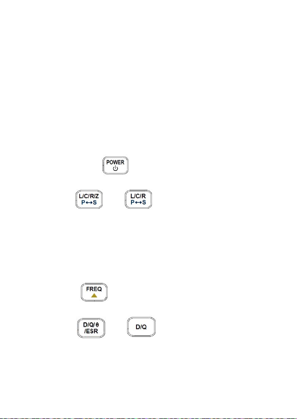
Note:
To achieve optimum pr ecision for a ll L, C, and R
measurements at either the highest or lowest
ranges, calibrate the meter before testing. See
“Calibration” section for details.
Inductance Measurement
1. Press down button for one second to turn
on the meter.
2. Press (or for model 878B) button
until “L” is displayed on the screen to select
inductance measurement.
3. Insert an inductor into either the input sockets or
connect alligator leads into the banana jack input
terminals and connec t the clips to the com ponent
leads as illustrated in Figure 10.
4. Press button until the desired test
frequency is displayed on screen.
5. Press (or for model 878B) button
to select between D factor, Q factor, θ angle, or
94
Page 97
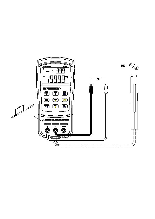
ESR measurement for secondary display. (θ and
ESR function for model 879B only)
6. Read the display readings for inductance
measured values and selected measured values
on secondary display.
Figure 10 - Inductance Measurement Setup
95
Page 98

Capacitance Measurement
WARNING Fully discharge capacitor BEFORE
inserting it into the instrument. Failure to do this may
result in damage to the meter and may cause
electrical hazards.
1. Press down button for one second to turn
on the meter.
2. Press (or for model 878B) button
until “C” is on the screen to select capacitance
measurement.
3. CAUTION: BEFORE inserting a capacitor or
capacitive component into the input sockets
or terminals, be sure to fully discharge the
component. Some larger capacitiv e
components may take longer to discharge. In
these cases, please allot enough time for a full
discharge. If proper dischargin g o f th e
component is not done correctly, it will
damage the input terminals of the meter.
4. Insert the DISCHARGED capacitor or capacitive
component into the input sockets or connect
alligator leads into the ban ana jac k input ter m inals
and connect the clips to the c omponent leads as
illustrated in Figure 11.
96
Page 99
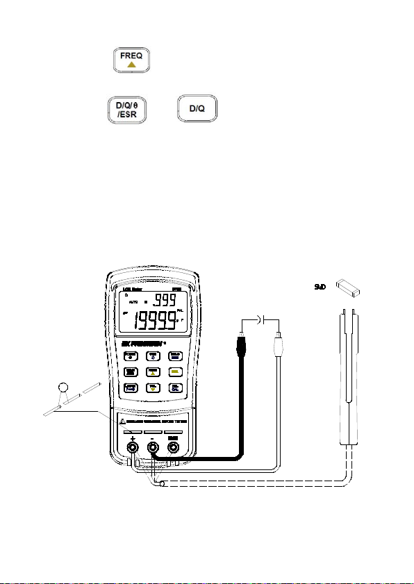
5. Press button until the desired test
frequency is displayed on screen.
6. Press (or for model 878B) button
to select between D factor, Q factor, θ angle, or
ESR measurement for secondar y display. (θ and
ESR function for model 879B only).
7. Read the display readings for capacitance
measured values and selected measured values
on secondary display.
Figure 11 - Capacitance Measurement Setup
97
Page 100

Resistance Measurement
1. Press down button for one second to turn
on the meter.
2. Press (or for model 878B) button
until “R” is on the screen to select resistance
measurement.
3. Insert resistor or resistive component into the
input sockets or connect alligator leads into the
banana jack input term inals and connect the clips
to the component leads as illustrated in Figure 12.
4. Press button until the desired test
frequency is displayed on screen.
Note: This meter does not provide a DC
resistance measurement of the component. It
uses an AC signal for measurement. For this
reason, some applications or device under test
may not give correct readings if they are designed
for measurement in DC.
5. Read the display readings for resistance
measured values.
98
 Loading...