

Page 1

5
MHz
SWEEP
FUNCTION
GENERATOR
with
DIGITAL
DISPLAY
KKPBEffi"
481-531-9-001
KKPBEffi"
22820 Savi ranch
www.bkprecision.com
2004
@
Parkway
Precision
B&K
-
Yorba
Linda,
CorP.
CA 92887
Printed
in
Taiwan
Page 2

TEST
INSTRUMENT
SAFETY
ae
io r
i,ou
;hock:ausrng
consrdered
,ioitage
such
vcltage.
klow
if
liou
Remove
hlgh-volrage
the cquipment
wrth
rn defective
large,
a
or
wet'
or
pocker" technrque
rhe
in
ground
good
e
the equrpment
dangerous
crn more
steer
ro
and
ilbser.,'e
and
housings
capacitors
equipment'
rnsulated
return
is connected
r-riruiirmps
lt)
hazardous
rnd
:rsrly
Droduce
.u.r"n,
icllo.ling
the
lncl
lfter
r:ested
belng
mat
iloor
whrle handling
path.
icontinued
urrent
e
,i
since
r lethal
irom
.*"0
lafety
onil
covers
removtnq
'rhe
anii
to stand
L)utiet'
ac
Lo Jn
inside
on
ro
it can
cunenr.
;-our
precauttons:
w!:n
power'
iocatron
\)n. rnd
an instrument
back
shouid
because
nsx
voltage
Drscharge
floor
a-re
could
.ra.
exposes
elecncel
An
be
hrgh
iactor
needlessly.
yourself
poinm
mate.al
damp
not
hand
provtde
trme
anf
\orrnai
exposed
low
pose an
ro
signrficantiy
voltage ls
volts dc
35
es
even
preven!
Don.t
L
high-vollge
possibie,
If
2.
,pp.tt
ntry
an
use
l.
certain
-1.
the
Use
metai
Whentestingacpoweredequrpment.rememberthateclinevoltageisusuallypresen'ronsomeDowerinputctrcuitssuchastheLln-rltf;wltcn'iuses
5
power
presenr.
rc rrns
or
threat
greater
wlth exposed
contacl
expose
object
the
reduce
trigh
circuits.
fam-liranze
unexpected
at
insuiated
surlaces
such
proven..one
lrme
rhat
i*nstormar.
equrpmenr
test
of
use
electncel
from
ilanger
of
rrnount
Jertarn
shock
pass ihrough
prociuce
Your
rn cese
hean
necessarv.
high
its
oi
insulated
rn
if thc
iven
coverl
hean
rhe
cunenl
lethal
a
.'lork
norrnal
acctcientei
of
')ff
Turn
voluge
work
Be
probe
equrpment
will
;top
under
hrbrts
'ontact
equlpment
However.
polnts
on
iurface
partlculeriv
turned
is
nost
ceftaln
should
whtle
"T
htch
:rrerui
orf
human
conditions
include
wrth
making
remember
place equlpment
to
to
'omelimes
:nust
iestlng
because
pefit',*ed
heerlbeets
rccepted
-rll
voitage
r hrgh
test
:onracinq
"tvotd
Htuher
:hat
'!ner:
\")ltxge
voltages
prrctic::
wlil
Y'lu
:jonnectron\
"ilita-ue
:rtgh
make
lnd
neuD)
r
is
n
Instruction
Manual
for
MODEL 40124,
5
MHz
SWEEPIFUNCTION
GENERATOR
with
Digital
Display
{ri'"
DT EE'E}"G'41|A'=
T'N
'-ITEUE'.IUII
22820
ranch Parkway
Savi
-
Yorba
Linda, CA
92887
Page 3

INSTRU}VIENT
TEST
TNTRODUCTION
SPECIFIC.\TIONS
CONTROLS
OPERATINC
Frequency
AND
TNSTRUCTIONS
Waveform Selectton
and
Considerations
Control
Cycle
Dury
TTL/CMOS
Sweep
Ourput
Consideranons
SAFETY
INDICATORS
TABLE
tiont
inside
.
.6
OF
page
cover
.3
..1
CONTENTS
Voluge Controlled
Ourput
Functron
.\IAINTENANCE
Disassembiy
Replacement
Fuse
Voltage Selection
Line
I
Instrument
3
9
WARR\\TY
IO
LIIV1ITED
ii
Protection
Considerations
Generator
ReassemblY
and
Repair
SERV
YEAR
ONE
Frequency
Operatton
Appiications
Servtce
INSTRUCTIONS
ICE
WARRANTY
Cuidebook
Li
L2
I3
L.r
lr+
i4
l5
li
I9
The
B+K Precision Model
versatrie
unit-waveform generation,
try),
added
accurate
calibrated
ity
analog and digital elecronlcs
ing, educational, and hobbyist
generator)
signal
and
ttequency sweep. Additionally, the instnrment provides
convenrence
determinatron of output frequency than is
dial. Coarse and fine tunrng controls
the
of
output
With
The heart
versatility.
this
of
produces preclslon
that
which
source
of a built-in frequency counter. This
tiequencv.
the function generator
the
unit has a
pulse
ln
.l012ASweep/Function
combrnes several functions
generation
the
engrneering, manufacturing, servic-
fields.
slne. square.
vast
(through
permit precision
number
VCC
is a
Cenerator
variable
permits
possrble
with
of lpplications rn both
(voltage-controlled
tnangle waves over
or
INTRODUCTION
is a
lnto one
syfune-
the
more
a simple
settabil-
the 0. 5 Hz to 5 MHz range.
uitrasonrc. and RF applications.
the
output to be rnjected directly
The sweep
rate and adjustable
Variable
to r
ramp or sawtooth
In addition to the above features,
controi
naily controlled frequencv is
symmetry of the
pulse generator
operating
generxtor
sweep time.
capabie
waves,
frequency.
This encompasses
A continuously
into circuits rt the correct
offers linear
of
and slewed
This is useful in
or
wavefbrm
output
generating
sine
an external
desirable.
subaudible, audio.
vanable
log
with
sweep
converts rhe instrument
rectangular waves
waves.
voltage
situations where an
dc
allows
offset
bias level.
variable
sweep
pulses.
or
may be used to
exter-
Page 4
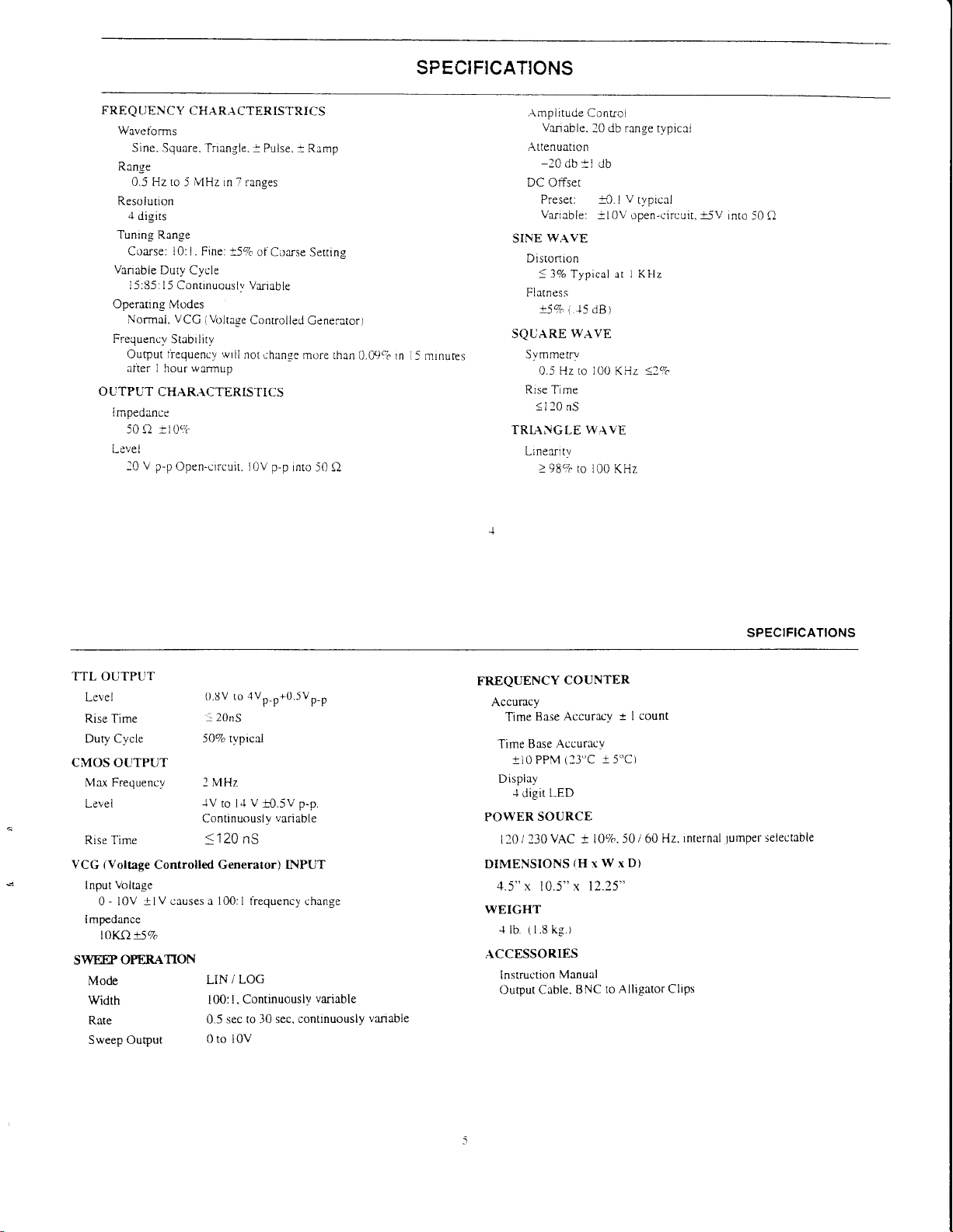
SPECIFICATIONS
FREQUENCY
Wavetbrms
Sine. Square. frrangle.
Range
0.5
ro
Hz
Resoiution
.l
digirs
Tuning
Range
Coarse: l0: I . Fine:
Vanable
Duty Cycle
l5:85: I5
Operating
Normai.
Frequency
Output fiequency wril
alier I
O UTPUT
I
mpedance
50 Q
Levet
l0
Continuouslv VariabLe
Modes
VCG
Stabrlitv
hour
CHARACTERISTICS
;-t09c
V p-p
Open-crrcuir. I
CHARACTERISTRICS
: Pulse.
5 MHz in 7 ranges
t57o
of Coarse
(Volrage
Conrrolled
warrnup
not chanse
p-p
0V
into 50 Q
: R,rmp
Setting
Ceneratorl
more rhan
0.09%
rn T-<
minures
,\mpiitude
Vrnrhle
Attenuatlon
-20
db
DC
Offset
Preset.
Varrable:
W.{VE
SINE
Disronron
<
3o/o Typical
Fi atness
!57o
SQUARE
Svmmetry
0.5 Hz to i}O
Rrse Time
<l 20
nS
TRL{NGLE
Linexfl ty
>
987c to
Conrol
+t
'15
(
WAVE
WAVE
'{l
rlh rrn oe rr
__
. _..>_ -vplcill
db
r-0.1
V
rypicel
-l0V
open-c'ircuit,+5V
I Kllz
at
dB
)
KHz 12Vc
I00 KHz
into -(0 Q
TTL OUTPUT
Lcvel
Rise Time
Duty Cycle
CMOS
OUTPUT
Max Frequency I MHz
Level
Rise Time
(Voltage
VCG
Input
0 - l0V
I mpedance
I 0Kf)
SWMOPERATION
Controlled Generator) INPUT
Volrage
+lV
causes a 100: I tiequenL^y
l57o
Mode
width
Rate
Sweep Output
{r.8v
lvp-p
to
: 20nS
5070 typical
-{V
Continuously
V
to l.l
<
120
nS
/ LOG
LIN
Contrnuouslv
I 00: I .
sec to 30 sec,
0.5
t0 5V
0to tOv
'0.5vp-p
p-p.
variable
change
variable
continuously
vanable
FREQUENCY
COUNTER
Accuracy
+
t I
5'c)
Time
Time Base
+t0
Display
.+
digit
POWER
L l0 / 230
Accuracy
Base
Accurlcy
(13"c
PPM
LED
SOURCE
VAC + i0%. 50 / 60
DIMENSIONS(HrWxD)
4.5"x
10.5"x
12.25"
WEIGHT
"l
(
1.8 kg.)
lb
ACCESSORIES
Instruction
Oupur Cable.
Manual
BNC
to Alligator Clips
count
Hz,
internal
SPECIFICATIONS
seiectable
lumpel
Page 5

CONTHOLS
AND
INDICATORS
(Refer
FFIONT
PANEL
1.
POWER
l.
R-{NGE
from
range
times the maximum.
the
3. FUNCTION
OUTPUT
.1.
OUTPUT
ar
mately
j.
DC OFFSET
Clockwise
directron
DC
6. OUTPUT
as
7.
TTIJCMOS
positron
output is independent of
contro ls.
8. CMOS LE\IEL Control. Rotating
the
Switch.
Switch.
I Hz ro lOlvlHz.
rs adjusted
and
output irequenc.v
1ack.
LEVEL Control.
the OUTPUT
20db
roution
while counterclockwise rotation tiom
in a negative directron.
offset
Jack.
the
supenmposed
the
of
amplitude
to Fig.1)
power
Turns
Selecrs ourDut
Switch rndicates maximum trequency oi
with
COARSE FREQUENCY
For example, rf the 100KHz
can
be adiusted {tom
Switch.
witbthis
Jack.
Selects sine. square, or
jack.
Control. Enabled
from center
Wavetorm
DC
TTL
ClvlOS
rhe
of
CMOS square
Controls the
Output
control.
selected by FUNCTION switch as
OFFSET
CMOS
or
LEVEL swrtch ( 13) rs output at
ihe
OUTPUT LEVEL and DC OFFSET
and
on
off.
irequenc;. range Seven rrnses
conrol to
range
is selected.
to
lOKHz
ampiitude of the signai
level
by
changes the DC offset
voitage
thrs control clockwrse lncreases
wave
decreased by approxi-
can be
the DC OFFSET Switch
is avarlable
wave, depending on the
square
at the TTL/CMOS
l00KHz.
triangie waveform
rn r posrtrve
center chanqes
this
rr
jack
this
(12).
weil
jxck.
This
jack.
0 L
the
VCG/SIVEEPJack.
When
SWEEP EXT
Cenerator
ttequency
decrease frequencv.
generated
an
DUTY CYCLE
t0
at
(14).
main OUTPUT
-20D8
I]
attenuated by
SWEEP
l2
sweep
control
WIDTH controi
trol
VCC/SWEEPJack
l3
SWEEP
mrc sweep
e linerr sweep
DC OFFSET Switch.
l4
OFFSET controi
CMOS
CMOS
input
by a DC
sweep
osciiloscope.
Roration
Switch.
INT/EXT Switch.
mode of
(18)
generator
oi
LIN/LOG Switch.
charactenstic
LEVEL Switch.
signal
Conrrolled
is
permits
and
voltage inpur at' thrs
Wben
voitage
Control.
tiom center
signal.
When engaged. the signai rr the OUTPUT
20db
operarion. Sweep rate
and sweep magnirude
at the TTL/CMOS
When
f I6;.
output frequencv
i9).
charactensttc.
When
(5)
by SWEEP
selected.
is avarlable at thrs
and
When
lack
cxrernal
SWEEP INT is selected the
Enabled
posrtron
When
reieased
When engaged f LOC)
in the L'eleased
engaged.
engaged. changes
jack.
EXT,{NT
Voltage
lhe
is
;ontrol of
jack.
the DtrTY
by
adjusts the
engaged
is controlled
is controlled by the
(EXT),
r DC
by
enables operation
generator
posrtlve
A
jack
connecr:on
for
CYCLE
dury cycle
(lNT)
SWEEPTIME
by
allows
externai
voltage
selects
positron
iLIN)
the TTL siqnai to
Switch
i
Conrroiled
Ltutpul
voltage
rnternallv
Swirch
of
jack
enables
SWEEP
con-
input
at rhe
loganth-
selecrs
of the
lt;
wiii
to
the
is
the
DC
16.
SWEEP
WIDTH
Control. Roration derermines
adjusting sweep stop frequency.
17. DUTY
18.
CYCLE Switch.
DUTY
CYCLE control i i0)
SWEEP TIME
amount
of
rime
Control.
to sweep
frequency.
19.
FINE FREQUENCY
frequency for
ease of setting
Control.
l0 COARSE FREQUENCY
put frequencv
irom 0. I to I trmes the
When
engaged,
in sweep
ltom
mode. rorerion
the start tiequency
Vernier
edjustment
fiequencv.
Control. Coarse
.elected
{r.r.
EEEEE.EEgg
16 15
Figure
1. Model 4012A
sweep width
enables
operation ot
determines
to rhe
stop
rhe ourpur
of
rdjusrment of the out
range.
bv
14 13
.L
,- ,*
12
Front Panel.
ll
COUNTER DISPLAY
waveform.
ated
GATE
72
t3
24
LED. lndicates
updated. When the
will
flash [0 times
through
second and
Hz and
lOK ranges are selected, the
when
l0
seconds. As the LED
KHz LED, lndicates whether
or KHz.
lnverl
Button.
,;
ru ru \
EE,E
Displays frequencv
when
l00K through
per
second
the I range
turns off. the display
Used to rnverr
CONTROLS
the frequency
l0M ranges
(every
0.
1 seconds).
LED will
is selected,
the
rhe
the
outDut sisnal.
AND INDICATORS
dispialr
rheLED
When
gener-
rhe l0
of inrernallv
counter
are
selected.
flash once everv
will
LED
is
flash every
updared
counrer rs readine
is
in Hz
Page 6

OPERATI
NG INSTRU CTIONS
The B+K
versatrle
over a broad
unit, it is recommended
ihat the eFfects of
so
be observed. Use
accustomed to the operaung
FREOUENCY AND
l. tnitially,
PRECISION
insrument. capabie
rrnge of tiequencies.
this manual as
venfy
DC
OFFSET
switches
symmetncal
in
are
waveform
that it be
vanous controls on
the
WAVEFORM
the
that
-20d8
(14),
the OUT
controls.
approprlate
Plug the unit
engaging
Select
engaging one
the
of
Seiect
switches
priate
Rotate the
frequency
quency
desired
(6).
lack
into an
POWER
the
rhe desired
wavetbrm
of rhe FUNCTION
waveforms are shown
the frequency of
(2).
The output
measurement
COARSE
the waveform by depressing one ot *re
units, KHz or Hz
(20)
to the approximate
controi can then be used to
value
.
frequency selected is rvailabie at
The
In addition,
Model4012A
producrng a
of
procedures.
Sweep/Function Generator
variety
of outDut
workrng
gatn
To
a
connected
required tbr reference
famiiiarity
inttrally io an osciLloscope,
the rtutput
waveforms can
until becoming
SELECNON
DUTY CYCLE ( 17), CMOS
(11),
and
SWEEP
position
unaffected by the sweep
switch t I
irequency rs displayed,
frequency
a digrral srgnai. erther TTL or
(released).
power
).
(SlNE.
switches
in Fig. 1.
control to
desired
easrly
source and
SQUARE. or
(3).
(23),
on
vaiue.
set the output
LEVEL ( 15),
INT/€XT
will produce
This
generaror and other
turn
TRIANCLE) by
Phase
with the appro-
aiong
the LED
dispiay.
quickly
set
The FII{E
to
the OUTPUT
ts a
waveforms
wtrh the
(12)'
a
rt
on by
reiattonships
R{NGE
the output
(19)
fre-
the
specific
is
CMOS
Square
Triangle
5. Adjust
0V
0V
Figure 2. Output
rvailable
OUTPUT"
the
LEVEL
riom maxrmum
oi
rttenuation
ma-rimum signal
conrol
-20db
Waveform and
at the TTI-/CMOS
section of
amplitude
is available by
factors can be
this manuai).
the oucpur
of
(4).
Rotation
to
db below maximum.
l0
is
level
10
jack
thrs ;ontroi
of
engagrng
combrned
(into
V p-p
Phase Relationship
(reier
i7)
as destred using the
An additional
-20d8
the
for a
50 Q).
"TTL/ClvlOS
to
lhe
vutes
ihe
swttch ill). The
total
oi
OTITPUT
amplirude
afienuation
-40db.
The
7.
A superimposed
engaging the
by
the DC
OFFSET control
or negative
introduced is independent
variedby
be
Offset does not
DC
CONSIDERATIONS
I
Counterclockwise rotation
creases the
maximum fbr the range
range is
counterclockwise.
l.
It is
center
This assures that rhe
rrving
3.
The
quency
vernier
4.
When
display
change will
ttequency
update untii the
DC component to
+l0volts
OFFSET
advisable to serthe
FINE frequency control provides
rs
shown rn
ourput frequency to
selected and
its
of
rotation
to rlnalize Lhe frequency
deviation ttom the
adjustment to easiiy set the fiequency
the I [Iz range is selected, rhe
rs updated
not be dispiayed until
progressrvelv
in
desired tiequencv
DC componenr can
DC OFFSET
opencircultedor+5 volts
affect the TTL/CMOS
the
the output fiequency
before
FINE
once every
swrtch
(5).
Rotation
the output signal.
the
of
OUTPUT LEVEL
Fie. 3
the
of
COARSE
selected i l0:
COARSE tiequency
FINE frequency
rpproximately
the
settrng
control will
sening.
COARSE
gare
l0
seconds.
smaller steps, warting
is obtained.
be added
l). For
COARSE
control
l0 seconds
ro the
(14)
to enabie
of this
control
The
into
output.;ack.
frequency
one-tenth
example.
control is
is approximately
controi to the
fiequency
not feach
approximately
setting.
to a precrse
trme
rs l0
The result
later.
for
output
signal
operation
positrve
adds a
DC
component
control
and can
50Q. The DC
The effect
control
of fie
if the
l0 K
set to fuil
I kHz.
rpproxrmare
control.
rts limit while
+5Vo
provides
This
value.
seconds
and the
ofa frequency
Adjust
the
display to
de-
fte-
rhe
OPERATING
of
Zero DC
A.
of
B. 0ffset Limits
G.
Offset
With Maximum
Signal.
Without
Clipping.
Excessive 0ffset.
Figure 3.
When
outputing
termrnate the
xs short as
possibie.
10V
+
-
10v
10V
+
OV
-1
0v
+1
-1
Use of DC
square waves
cable inro
AA
OV
VV
\&___4&
Positive
DC Otfset
0V
OV
0v
T*'ti*
DC 0ffset
OFFSET
or when using
50 O ro
minimize
INSTRUCTTONS
A-A-
-V-V
Control
the
nnging.
Also,
Negative
DC
offset
J3%1,J,1
T'fL
output,
keep cables
Page 7

OPEFTATING
INSTR
UCTIONS
6'Rememberthat|.heoutputsrgnaiswrngofihegerterltorlsllmlted
to
combined
slightly
.oidi,ion,
output
scope
without
DUTY
The
output
a
For
cycie
ment
a sine
wrth
Model
The
Select
1.
Engage
CfCI-n
fiom
changes
of
bottom
V
Adjust
-10'/olts
above
stgnal
shJuld
undesrrabie
CYCLE
DUTY
waveform,
square
(ratio
of
pulse
a
into
wave, a
,10
the
center
each
waveform
lng
rrv
the COARSE
clrculted
open
peak-to-peak srgnal
encountered
CYCLE
wave' syllmetry
'high"
tlAprovides
waveform
the
control
the sine
pair
the
ls'iels.
ihs5s
or
is
Large
make
to
usJd
be
cllPPrng
CONTROL
conrol
produce'waveshaDes
to
''low"
to
generator.
distoned
DUTY
results
of
durv
For
waveshape
for
desired
CYCLE
(
for
l0)
an
in
trtangle
rnd
4. Counter-clockwise
Fig.
erch
rn
setting
cycle
and
volts into 50
--<
Dr
enci
iilustrates
3
Fig
when ustng
rf
a large
sure
can be
varlatlon
time)'
tnangle
a
symmetry
either
switch
desired
the
increase
waves
Pair'
resu
FtrriE
DC
that
used
etfectlveiy
S
lts i n r s
frequency
alnounts
cailed
variation
lNE.
waveshape
in square
Q rnd
oifset
DC
the-vattous
offset'
the DC
is requrred'
offset
the desrred
to aiter
as those
such
ro changtng
convenlng
the
wave,
a slewed
SQU
(17)
and
wave duty
as shown
rotalion
iight
controis
Clipptng
signal
the symmetry
shown
resuit
sine
l57o
from
or TRIANCLE'
ARE
adjust
Clockwise
the
in
ehrnge
to rhe
applies
'rccurs
operrting
desired
the
If
an oscrllo-
is obtatned
ci
in
Fig
the
tne lnstru-
ramp'
is a
produced
is
ro 85Vo
DUTY
rhe
rotatlon
cycle'
wlvelorm
top
in the
resuits
in irequency
required'
as
the
l'
duty
and
and
PU ISe
(Square)
Siewed
ne
Si
(Sine)
Figure
4. Effects
of Symmetry
Variafion'
TTUCMOS
TTUCMOS
The
f itner
output.
output
The
sync
external
for
,our."
."n,.
"",p*
L select
'
;;il;il.
have no
When the
L
"",;;;
irr"'Cuos
ronting
SWEEP
Select
I
(13)
LIN/LOG
the
Set
L
"Jj"rii"g
counter,
Engage
3
sweep
S*eep
is
and
OUTPUT
output.;ack
TTL
fixed
a
is
putse tbr
"x".crsrng
postttve
logic
wllh
oscilloscopes
iengthinoulA
the
effect
it.
on
ourpur
the
frequency
desired
CMOS
rrVCuoS
*'.
"i
LEVEL
CMOS
the
OPERATION
relecsed
the
sweep
LINEAR
in
switch'
frequency
starting
"col'nsB
,r,"
SWEEP
the
vaned
be
can
the
is
time
affected
not
provides
oi
respect
ground
to
CMOS
variable
a
or
Because
circuits
mrnimized
be
and
range
livnr
TTL/CMOS
the
at
signal
LEVEL
same
swrtch
jack'
Select
adjust
and
switch
LEVEL
control
leavrng
by
poiition
the
or
(highest
frequency
EXT/INT
rdjusting
oy
switch
the
whetheithe.s.weep
wldtn
sweep
the
by
nse
fast
a
ourput
and
variab-le
a
as
the
of
nnging
limit
to
adjust
DC
and
(15)
is OFF'
a CMOS
the
(8)'
SWEEP
sweep
LOG
tiequency)
control
(ll) The
SWEEP
trme
ievel
ca1
frequency
rise
fast
trequency
the
oFFSET
jack'
a
-s1e1at
of
level
LIN/LOG
by
of
and
TIIVIE
lineer
rs
wave
square
available'
is
be used
as
an
signal
this
of
time
and overshoot'
controls
controls
is
srgnal
fiL
engxsrng
uv
the
engaglng
the
observrng
duration
control
or
by
signal
swttch
the
by
sweep
the
the
of
(
l8)'
loganthmtc'
i0
OPERATING
(lowest frequencVl-1p
sweep
.1.
'
The
frequency
end
UVi"i"ii"g-tne
g.i.ratly
iiouta
it
because
front
The
5.
signat
which
osctlloscope,
dtt
;;;;;t
response
ol
eouioment.
freouencv
output
the
lf
,fi"
^".1
i"pri,
produces
mode
However,notethatswltcnlngtoLoCsweepstillproducesalinear
il;i;y;
rnternal
"i"* .
,nJ
Irme
VOLTAGE
The
"ri"g
iack.
i,."."r.."i
;;;.;p;
ramp,
log
"u"-rog*thmic
Sieep
ttt"
u,"
base
as
a
CONTROLLED
Model 4012A
"i"al
.i
."
externally
The
ut',t
:;;;**"1i
Select
l.
the
the
decreases
r:f the
SWeBp
be
largely
is
VCG/SWEEP
panel
De
can
glve an
to
meiirod
equlpment
audlo
response
The
left
from
circuit
the
of
SWEEP
amplltude
the
This
also
output
horizontal
can
"ontrol
"pptt"tt
i*gJ
"
ti
iro
ffequency
output
desired
WIDTH
after
made
dependent
as
used
X-Y
commonlv
is
will be
on
right
to
to be
the
to
output
is bEcause
Decomes
put the
graph,
as
solely
det-lection
FREOUENCY
operated
be
vtltage
uo"ttogi'will
t*itthes
the
with
by
tiequency
control
setting
that
on
(9)
jack
thshorizontal
display
used
bandwidth
thl
or
displayed
X-Y
the
connected
ts
tested
horrzontal'
frequency
vs'
horizontal
the
logarithmic
scope
a scope
source
voltage-co-ntrolled
as a
applied
the
rnd
coARsE
100
about
and
range
INSTRUCTIONS
(16)
starting
the
settlng'
provides
deflection
signal
of
testing
when
of
high
disptay'
to
setting
plot.
sweeping
the
when
in tim.e.base
back
Use
trigger'
OPERATION
V!^G^{S*EEP
t?-h.l
the
-vary
frequency
control
times
wavelolrn
adiusted
be
adjustment
This
frequuency'
rnternal
the
signal
amplitude
frequencv
the
amplifiers
or
frequency
verttcal
the
scope
the
mentioned
signal'
tY""p
1o,",1.fl
operatlon
scope's
the
generator
frequency
controls'
(a
tull
at
100:
Applyrng
clockwtse
ratio)'
I
ramp
an
tbr
vs fre-
other
iow
to
scope
X-Y
to
above'
the
linear
input
which
by
is
u
Page 8

OPERATING
the stantng
L Set
posrtrve DC
the frequency.
rlecriase
to
maxrmum
iel Jt
kHz,
is 100
kHz.
To operate
3.
4.
5. Do
OUTPUT
Use
in;ection
funcnon
ihe
other
control.
going ramp
positiue
voluge
iamp
adjusted
can be
Specific
to ttr"
by appiying
VCG/SWEEP
cause
the
generator output
frequencres
vCCiSwEEP
apply
not
any
generator.
PROTECTION
when connecting
care
point.
generator
low
than
Model'10
The
INSTRUCTIONS
irequency
voltage ro rhe
voltage from
A
a factorof
by
CW
appiying
functton
rhe
increases,
by
a stePoed
more
input
shrft
funher
Excessive
causes
can
shouid
values that
dc
l2f$s
wrth
VCG/SWEEP
100 if the
rotetton.
V
-10
generator as
to rhe
signal
irequency
the
varying
the
can be selected
jack
input
volrage.
dc
+t5
than
jack.
Inputs
in the
CONSIDEFIATIONS
the function
voltage at the
internai
never be
can be matched
overload
COARSE
rhe
inputiack
V
will cause the
+10
0 to
COARSE
crrmpie.
For
wrll change
VCG/SWEEP input
frequency
or
voits
fuequency
damage.
connected
protected so
ti
the
a sweep
decrelses
of
by applying
fiequencies
the
(dc
or
of more
and could
generator ourput
point of signai
Under
with the DC
control
to decrease
i9
t
frequency
trequencv
tne
outpur
rhe ramp stgnal'
dc + rc
than l5
to ar
that shortlng
contrcl
irequencu
;rartrng
frequency
generator' applv
jack.
The rate
of sweep
dc
fixed
a
can be
peakl to
voits
cause damage
to a
rnjectton
normai operlilon'
external
OFFSET
the ourput'
Appty
to I
As
voltage
stepped
wrll not
stgnal
of
voltage
the
the
the
il
rs
r
to
lrth :he
;erres
by
damage
Damage
the iunction
of
ourput
toiiowing
The
user
The
1
ro
identifo
a logic
points is rarely
2.. If rn doubt
voitage
connecting
When applying
3.
po'nt
.onriining
ihe dc
-1.
Connect
CMOS
under
manual.
the
When the
5.
encedusers,
probe or
aqainst
continuousiv.
even
wrll nol
OUTPL'T
connection
iype
thrs
cf
protectlve
understand
should
valid signai
a
of
input
hrgh
about
at
present
function
the
the
a
the
at
levei
the TTL
only
output
adjust
and
rest
functton
thecircultofFig
test clip
voltages
extemal
llcl
Lo excessive
occurs
usually
generator
lhe sal-ety
main
set.
io a
measures
injection
gate, etc.).
enough
of a signal
intended
the
generatof output
output
main
adjust
levei,
dc
output
only
output
to CIIOS
CMOS
the
generator
will
It
up
to
external
voltage
are strongly
the
The
damage
to
matches
circutts
rs
5 could
protect
+
to
damage
ieuse
'A' fuse
netp
Jrctcct
voltage
accidentaliv
by
rn *te
recommended:
equipment
pornts
voitage
point of signal
oithe
the DC OFFSET
to TTL'level
LEVEL
used
20
under
,'ie:
the
at
lnstrument
lhe
rnjection
to thal
iunctron
the circuit
Measure
control
by students
added
be
output
the TTL
volts'
hc tnstrument
connecting
equipment
base
valrd
generator
crrcuits'
the
into
under test'
weil
lest
of r tranststor'
signai
point,
measure
injecdon
polnt'
to a clrcult
concrol
voltage
Connect
rlf
Vcc
the
rnstructed
as
or other
yourTTL
generxtor
the
of
injection
lnexpen-
:-;om
rhe
enough
the
before
so that
the
circuit
ln
ourput
been ldded tn
has
FUNCTION
GENERATOR
TTL OUTPUT
Figure
5.
(+)
TTL
Circuit
Protection
for
150 c2.
of TTL
W
2
Output'
t2
FUNCTION
B+K
descnbes
tletarls.
an explanation
tiee ofcharge
with fie
GENERATOR
Precision
numerous
includes
It also
function
of
by
Model
4012A
OPERATING
APPLICATIONS
"Guidebook
a
offers
rpplications
a
for this
glossary of
function
generatorcucuitoperation
mailing
and
out
filling
GUIDEBOOK
Function
to
instrument'
geneutor
postage
the
INSTRUCTIONS
Generators"
including
tennlnology
lt may
which
hook-up
end
be obtrined
pard card enciosed
ll
Page 9

tl
--- --
WARNIXG
iOilowtng nsirucltans
Tne
qLjattfted
servtce
elecirrcal shack,
ather :han
strucltans
Remember
iine vcltage
merl
iurneC )lf
cantalnec
Jnless
ihat )c
input crrcutts any ttme
pluggeo
rs
Alwavs Jnalug :he
eralor Sefare
I
ior
persannel
dc
vcu are
tFe
are
cnty.
.ot
oerlorm servtcinq
n
lhe
aDerettrE
quaiilted:o
,s
voitaEe
cresenl
lhe
rnlo
an ac
cu(let.
'uncltao
cerlormrng serrtce
)se DV
Tc
avcrd
dc -co
instru-
even
)en-
cTCCe-
'n-
aF
,f
oures
DISASSEMBLY AND
In order to trccess the
must be removed. Disassembly and reassembly procedures
loilows:
REASSEMBLY
line ;elector
lumDer,
th€ bottom
half oi rhe case
DISASSEMBLY
l. Unpiug the
Blue rubber bezel rhat borders Lhe tront panel
upsrde
L Remove
the two bottom screws toward
ro remove
i. Lrft ofi ihe bottom cover.
lunction generator
down.
lour
lhe
screws
the two caps that hold
irom
irom
the
the front oi the
the
po*er
bottom of the case To access
rrlr
stand shafts.
Remove
source.
tnd turn
case.rou mav need
MAI
NTENANCE
are as
ihe
the unir
ll
REASSEMBLY
back
slots :n the
panel.
push the
bottom
iour screws, lhe
protective
the
bottom
half do'rn onio lhc
Blue bezel.
1. Line up the
lhe
i. Crreiully
L Repiace the
shafts. rnd
FUSE REPLACEMENT
l. fo repiace
the fuse holder
the correc! iuse
:. To replace
described.
Locate the
l.
board mounted
value
l. Rerssemble case cs
the lrne fuse.
the output
iuse holder.
iuse 0.lA
located
value
to the
slow blow
use a tlal blatle
under the lrne lr;rd
is used.
fuse, disassemble
{t is located
front
fuse.
previousl_v described
LINE VOLTAGE SELECTION
previousl;- described.
l. Disassemble lhe
l Locf,re the
boaril
bchrnd ihe
case as
voitrge
line
power lranstormcr
selection
;ase half
two caps lhat hold ihe
panel.
with
screw
the case as
the
on
Replace onlv
connetor. It
:he i.^.t
top
drjver
receptrcle. Ensure thal
output amplrfier PC
rs
located on the PC
half
with
6.--l ..1
trlt stand
puil
io
out
orevrouslv
the correct
OPERATING
the connectot
Unplug
the connector
Push
that [he.orrect
V
tbr ll0
Rerssemble
INSTRUCTIONS
pulling
by
lhe desired
onto
is instaiied
fuse
()peratlon
case
(J
L\ slow
or
as descnbed
up.
straight
voitdage selectton
iuse holder'
in the
for 130
blow
irbove.
pin Be sure
i0 ] A slow
\'operatlon)
blow
INSTRUMENT
Becluse
inslrument
B+K
B+K
thrs
the
TIO
out
oi
reparr
PRECISION
PR-ECISION
even
service.
insructrons
ponron
NS
wiirranty.
of
REPAIR
SERVICE
the specralized
calibration.
rnd
for thls servlce.
authonzed
instrument
if the
given in the
thrs manual.
of
lnd
skills
customers
man)'
agencies
sewtce
is no
WARRANTY
rs r nomtnal
There
equipment
lest
pret-er
We matntain
for thts
warranty. follow
under
longer
SERVICE
charge
requtred
rely upon
to
a netw(rrk
purpose
To
use
INSTRUC'
for insruments
for
of
l5
Page 10

NOTES
i6
WARRANTY
(For
U.S.A. and its
l. Refer to
instructlon manual tbr adjustments that may be
l. {f
nencins with
ctrton or doubie-packed). with
,1. Enciose r
aooress.
your
If
wnte
the
MAINTENANCE sectton of
theabove'mentioneddoesnotconecttheproblem)-ouareexpe- 5. Deliver to.
-v-our
letter
list
authonzed B+K Precision \ervice
of
to:
pack
unit.
describins
it
the
Droblem
secureiv
your
B+K Precision
applicable. recetpt.
iprel'erably
rnd rnciude
rgencles
B&K
22820
SERVICE
Overseas
-l
in the
onginal nearest B+K
vour
name
and
has
been
mrsplaced. contact
Ranch
Linda,
Corporatlon
ParkwaY
92887
CA
Precision
Savi
Yorba
www.bkPrecision.com
(800) 462-9832
INSTRUCTIONS
Territories)
proof
Enciose
unit;.
your
distributor tbr the name
purchase
of
or ship PREPAID
Precision authorized sen,ice rgency
date: that is.
rLIPS preterred
vour netrest
of
a dated copy of the sales
rn
Lr S.A.t to the
rsee
list enclosed
service agencv. or
ll
Page 11

NOTES
LIMITED ONE-YEAR
B&K Precision Corp.
thereof,
data of
B&K
component
form
To obtain
mailing the enclosed warranty card
Linda,
Exclusions: This warranty does not apply in
or
alternated,
B&K Precision Corp. shall not
limitation damages resulting from loss
consequential
This
state.
will
purchase.
Precision
a sales
warranty
CA
a result
as
warranty
be
parts.
receiot.
92887within
defaced
warrants
free from defects in
will, without
Corp.
Returned
coverage in the U.S.A.,
of unauthorized alternations or repairs. lt is void if the serial
or
damages,
gives you
to the original
workmanship and
charge, repair or replace, at
product
fifteen
removed.
so the above
specific rights and
(15)
liable for
be
must
to B&K
days from
purchaser
be accompanied by
this
Precision
any consequential damages,
of use.
limitation
Some states do
you
WARRANTY
product
its
that
period
materials
product
proof
the event of
or exclusion
may have other rights,
must be registered
Corp.,
purchase.
of
for
a
its'
option, defective
proof
of the
22820 Savi
misuse
not allow limitation of incidental or
may not
and the component
years
one
of
purchase
by completing and
you.
to
vary
Parkway
number is
ranch
abuse of the
or
including without
apply
which
from
product
date in the
product
from state-to-
parts
the
or
-
Yorba
t9
Page 12

FUNCTION
GENERATOR
Fnee
".",.:?B'JJ?"*'
'l$sii".'
JJ[*E
ffigr'
APPLICATIONS
"B&K-Precision's
A copy
Generators"
purchasers
of the
Applications
of B&K-Precision
MANUAL
Manual
CONTAINS:
Numerous
Gain
Features
.
Function
.
Typical
Application
From
Most
The
And Capabilittes.
Generator
Function
Generator
Your
Terminology.
Usage
.
Function
Generator
Obtain
your
Theory
free coPY
www.bkprecision
Gurdebook
is offered
Functron
Examples
To Functjon
FREE to
Generators.
Showtng
Function Generator's
Controls
Of
And
Operation
vistting
bY
com
Hcw
Their
To
TEST INSTRUMENT
icontrnued from
6. Some equipment with
television
tbr servtcing,
lnstruments or the equrpment
equlpment,
i604 Isolation Transtbrmer.
ac equipment as
I
On
exposed elements
8.
B+K Precision
as
orswrtchingmeans.A'cnticaicomponent"isanvcomponentofelitesupportdeviceorsvstemwhosefailuretoperformcanbereasonablvexpecred
to cause tailure
9.
Never work
recommended.
receivers and
always connect
test
instruments or any
a cntical component
alone. Someone
a rwo-wire
a serious shock hazard
audio equipment. A
"hot-chassts"
equipment with
ground.
at earth
products
of
that
iue not
in e lit-e
devrce
power
ac
under test may
an isoiation transtbrmer
or Model 1653
unless
authorized tbr
support device or
or system. or to atfect
should be nearby
cord.
including
plastic
exrsts if the chassrs
result tiom
or 1655 AC Power
you
are sure it
it -1-wrre
use in any
system.
to render
some with polanzed power plugs,
wooden
or
rs
connecting
between the
has
isolated
ln
power plug.
rc
applicatron involving
Here,
its
saf'etv or effectiveness.
aid if necessary.
inside front
cabinet insulates the
touched.
Not only does this
ground
the
ac outlet and the equipment
Supply
is suitable tbr most applications.
chassis
use
only I 3-wire outlet. This rs
"direct
contact"
cover)
chassis to
lead
of most test instruments
or ln earth
direct contact between
refers to
Trainrng in
"hot
is
the
protect
present
under test.
ground
chassis.
connection
any
CPR
icardio-pulmonary resuscitation)
chassis"
the
customer. When
a dangerous
I safety ieature
"hot
to
a
The B+K Precision
To
be on the
product
our
tiom
or
shock hazard,
to
type.
This includes
the cabinet
chassis".
and
our equipment via
To test
side.
saf-e
to keep the
the
human
SAFEW
most recenr
is
"hot
treat
all two-wrre
housing
bodv.
any cabling
aid
removed
chassis"
or other
9r tbr
is
but clamage
Model TR-ll0
firsr
to
test
use
hiehiv
or
 Loading...