

Page 1
OPERATING INSTRUCTIONS
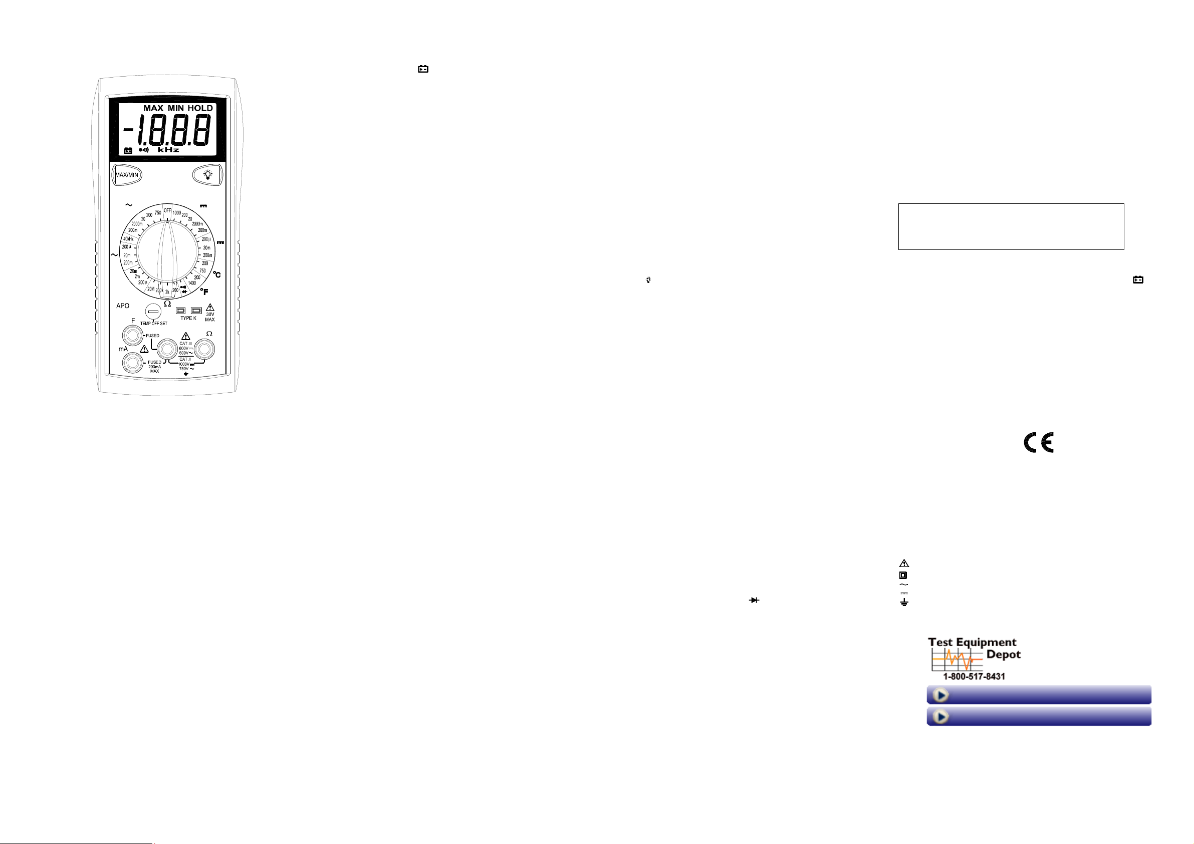
MODEL 2706B
DIGITAL MULTIMETER
2706B
V
A
F
COM
SAFETY INFORMATION
The following safety information must be observedto ensure maximum personal
safetyduring the operationat thismeter:
Use the meteronlyasspecified in this manualorthe protection providedbythe
metermightbe impaired.
Test the meteron a knownvoltage before usingit to determineifhazardous
voltage is present.
Do not use the meter if the meteror test leadslookdamaged, or if you suspect
that themeteris notoperating properly.
Neverground yourselfwhentaking electricalmeasurements.Donot touch
exposed metal pipes, outlets, fixtures,etc., which might be at groundpotential.
Keepyourbody isolated from groundby using dry clothing,rubber shoes, rubber
mats,oranyapproved insulating material.
Turnoff power to the circuit undertestbefore cutting,unsoldering,orbreaking
the circuit.Small amountsofcurrent can be dangerous.
Use cautionwhen workingabove60Vdc or 30V ac rms.Suchvoltages pose a
shockhazard.
When usingtheprobes, keep your fingers behind the finger guardsonthe
probes.
Measuring voltagewhich exceeds the limitsofthemultimeter may damagethe
meterandexpose the operatorto a shock hazard. Alwaysrecognizethe meter
voltage limits as statedonthe frontofthemeter.
V
A
HzV
SPECIFICATIONS
Display: 3½ digitliquid crystaldisplay (LCD) with a maximum reading of 1999.
Polarity:Automatic, positiveimplied, negative polarityindication.
Overrange: (OL) or (-OL) is displayed.
Zero:Automatic.
Lowbattery indication:The
belowtheoperating level.
Measurement rate: 2.5 timespersecond, nominal.
Auto poweroff: Approx. 25 minutes.
Operating environment: 0℃ to 50℃ at < 70%relative humidity.
Storage temperature: -20℃ to 60℃,0 to 80% relativehumidity.
Accuracy: Statedaccuracy at 23℃±5℃, < 75% relative humidity.
Temperature Coefficient: 0.1 x (specifiedaccuracy) per ℃. (℃ to 18℃, 28℃ to
50℃).
Altitude: 6561.7 feet (2000m).
Power: Single standard 9-volt battery, NEDA1604, JIS 006P, IEC 6F22.
Battery life: 150 hours typicalwithcarbon-zinc.
Dimensions: 165mm(H) x78mm(W)x42.5mm(D).
Weight: Approx. 10.0 oz.(285g) includingholster.
Accessories: One set test leads,onespare fuse, 9V battery (installed),and
Operating Instructions.
is displayed when the batteryvoltage drops
" "
DC VOLTS
Ranges: 200mV,2000mV, 20V,200V,1000V
Resolution: 0.1mV
Accuracy: ± (0.5% rdg + 1 dgt)
Inputimpedance: 10MΩ
Overload protection: 1000VDCor750VACrms
600VDC/AC rms 15 seconds on 200mV range
AC VOLTS (50Hz- 500Hz)
Ranges: 200mV,2000mV,20V, 200V, 750V
Resolution: 0.1mV
Accuracy:
±( 1.2% rdg + 5dgts) on 200mV to 20V ranges
±( 2.0% rdg + 5 dgts) on 200V, 750Vranges
Inputimpedance: 10MΩ
Overload protection: 1000VDCor750VACrms
600VDC/AC rms 15 seconds on 200mV range
CURRENT
Ranges: 200uA, 20mA, 200mA
Resolution: 0.1uA
DC accuracy: ± ( 1.0%rdg+ 1 dgts)
AC accuracy: (50Hz ~ 500Hz)
±( 1.5% rdg + 5dgts)
Inputprotection: 0.25A/500V fast blowceramic fuse
RESISTANCE
Ranges: 200Ω, 2kΩ, 200kΩ,20MΩ
Resolution: 0.1Ω
Accuracy:
±( 1.0% rdg + 4 dgts) on 200Ωto 200kΩranges
±( 2.0% rdg+ 4 dgts) on 20MΩrange
Open circuit volts: 0.3Vdc (3.0Vdc on 200Ωrange)
Overload protection: 500VDC or AC rms
CONTINUITY
Audible indication: Less than 100Ω
Response time: 100ms
Overload protection: 500VDC or AC rms
DIODE TEST
Test current: Approx.1.0mA
Accuracy: ±(1.5% rdg + 3dgts)
Open circuit volts: 3.0Vdc typical
Overloadprotection:500VDC or AC rms
CAPACITANCE
Ranges: 200uF, 2mF, 20mF
Resolution: 0.1uF
Accuracy: ±(4% rdg + 10 dgts)
Test frequency: 21Hz
Test voltage: <3.0V
Inputprotection: 0.25A/500V fast blowceramic fuse
FREQUENCY (Autoranging)
Range: 10Hzto 40kHz
Resolution: 1Hz
Accuracy: ±(0.1% rdg+ 3 dgts)
Sensitivity: 3.5V RMS min
Overload protection: 500VDC or AC rms
TEMPERATURE
Ranges: -35℃ ~ 750℃,-30℉~ 1400℉
Resolution: 0.1℃, 0.1℉
Accuracy:
±(1.0% rdg + 1℃) 0℃ ~ 400℃
±(3.0% rdg + 3℃) -35℃ ~ 0℃, 400℃ ~750℃
±(1.0% rdg + 2℉) -4℉ ~ 750℉
±(3.0% rdg + 6℉) -30℉ ~ -4℉, 750℉ ~ 1400℉
Sensortype: K-type thermocouple
Overload protection: 60VDC or 30V AC rms
OPERATION
Beforetaking any measurements, readtheSafety InformationSection.Always
examine the instrumentfordamage, contamination (excessive dirt, grease,etc.)
and defects. Examine the test leadsforcracked or frayed insulation. If any
abnormal conditionsexist do not attempt to make any measurements.
MAX/MIN
PressMAX/MINonce begins recordingMINand MAX.
PressMAX/MINtoselectcurrent readingMIN or MAX.
Holddownfor2 secondstoexitMAX/MIN function.
Backlight
Pressthe button to activate the backlightforapproximate4.5minutes.
Voltage Measurements
1.Connect the red test lead to ”VΩ”jack and the blacktestleadtothe ”COM”
jack.
2.SettheFunction/Range switch to the desiredvoltage type (AC or DC) and
range. If magnitude of voltageis not known, setswitch to thehighest range
and reduceuntil a satisfactoryreading is obtained.
3.Connect the test leads to the deviceor circuitbeing measured.
4. For dc, a (-) sign is displayed for negativepolarity; positivepolarity is implied.
CurrentMeasurements
1.Connect the red test lead to the ”mA” jackandtheblacktestlead to the
"COM"jack.
2.SettheFunction/Range switch to the DC or AC ranges.
3.Remove power from the circuitunder test and open the normal circuitpath
wherethe measurement is to be taken. Connect the meter in series with the
circuit.
4.Apply power and read the value from the display.
Resistance and Continuity Measurements
1.SettheFunction/Range switch to the desiredresistance range or continuity
position.
2.Remove power from the equipment under test.
3.Connect the red test lead to the “ VΩ” jackandtheblacktestleadto
the ”COM” jack.
4.Touch the probes to the test points.In ohms,thevalue indicatedinthe display
is the measuredvalue of resistance. In continuity test,thebeeper sounds
continuously, if the resistanceislessthan 100Ω.
Diode Tests
1.Connect the red test lead to the “ VΩ” jackandtheblacktestleadto
the ”COM” jack.
2.SettheFunction/Range switch to the “ “ position.
3.Turn off powerto the circuitunder test. Externalvoltage across the
components causesinvalid readings.
4.Touch probes to the diode.A forward-voltagedrop is about 0.6V(typical for a
silicondiode).
5.Reverse probes.If the diodeis good, “OL”is displayed. If the diode is shorted,
“000” or another number is displayed.
6. If the diode is open,“OL” is displayed in both directions.
Capacitance Measurements
1.Set theFunction/Range switch to the desired F (capacitance) range.
2.Connect the red test lead to the “F “ jackandtheblack test lead to the
“COM“jack.
3.Touch the probes to the capacitor. Observepolarity whenmeasuring polarized
capacitors.
4.Read the capacitance directlyfromthedisplay.
5. Discharge the capacitorbefore taking capacitancemeasurements.
Frequency Measurements
1.Set theFunction/Range switch to the “40kHz”position.
2.Connect the red test lead to the“VΩ” jack and the black test lead to the
“COM“jack.
3.Connect the test leadsto the pointofmeasurement and readthefrequency
fromthe display.
Temperature Measurements
1.Set theFunction/Range switch to the desiredtemperaturerange: ℃, ℉
2. Remove leads and slidetheTemp switch to the right to close lead jacks.
3.PluganyK-typethermocouple directly into the meter to measure temperature.
4.Taketemperaturemeasurementusing the thermocouple probe and read the
temperature from the display.
Temp offset adjustment
The OFFSETcontrol is set at the factoryto allowforthevariations foundin
standard thermocouples. By adjusting the OFFSET control, you can optimize
measurement accuracy for a particularthermocouple at a particular
temperature.
MAINTENANCE
WARNING
Removetestleads before changing batteryor fuse or
performing any servicing.
Battery Replacement
Poweris supplied by a 9 volt battery. (NEDA1604, IEC 6F22).The
on the LCD displaywhen replacementisneeded. To replace the battery, remove
the threescrews from the back of the meter and lift off the frontcase.Remove
the battery from case bottom.
" "
appears
Fuse Replacement
If no currentandcapacitancemeasurements arepossible. Checkfora blown
overload protectionfuse. For access to fuses, removethethreescrews from the
back of the meterandliftoffthefront case.
Replace (F1/current measurements) (F2/capacitancemeasurements)only with
the original type 0.25A/500V,fastacting ceramic fuse.
Cleaning
Wipe the casewitha damp cloth andmilddetergent. Do not use abrasives or
solvents. Dirt or moisturein the terminalscan affect readings.
Safety: Conforms to IEC61010-1 (EN61010-1), CATII 1000V, CATIII600V, Class
II, Pollution degree2 Indooruse.
CATII: Is formeasurements performed on circuits directlyconnectedto the
low-voltageinstallation.
CAT III: Is for measurements performedinthebuilding installation.
EMC:Conforms to EN61326.
The symbolsused on this instrumentare:
Caution, refer to accompanying documents
Equipment protectedthroughoutbyDouble insulation(Class II)
Alternating current
Directcurrent
Ground
99 Washington Street
Melrose, MA 02176
Phone 781-665-1400
Toll Free 1-800-517-8431
Visit us at www.TestEquipmentDepot.com
Back to the BK 2706B Product Info Page
 Loading...