

Page 1
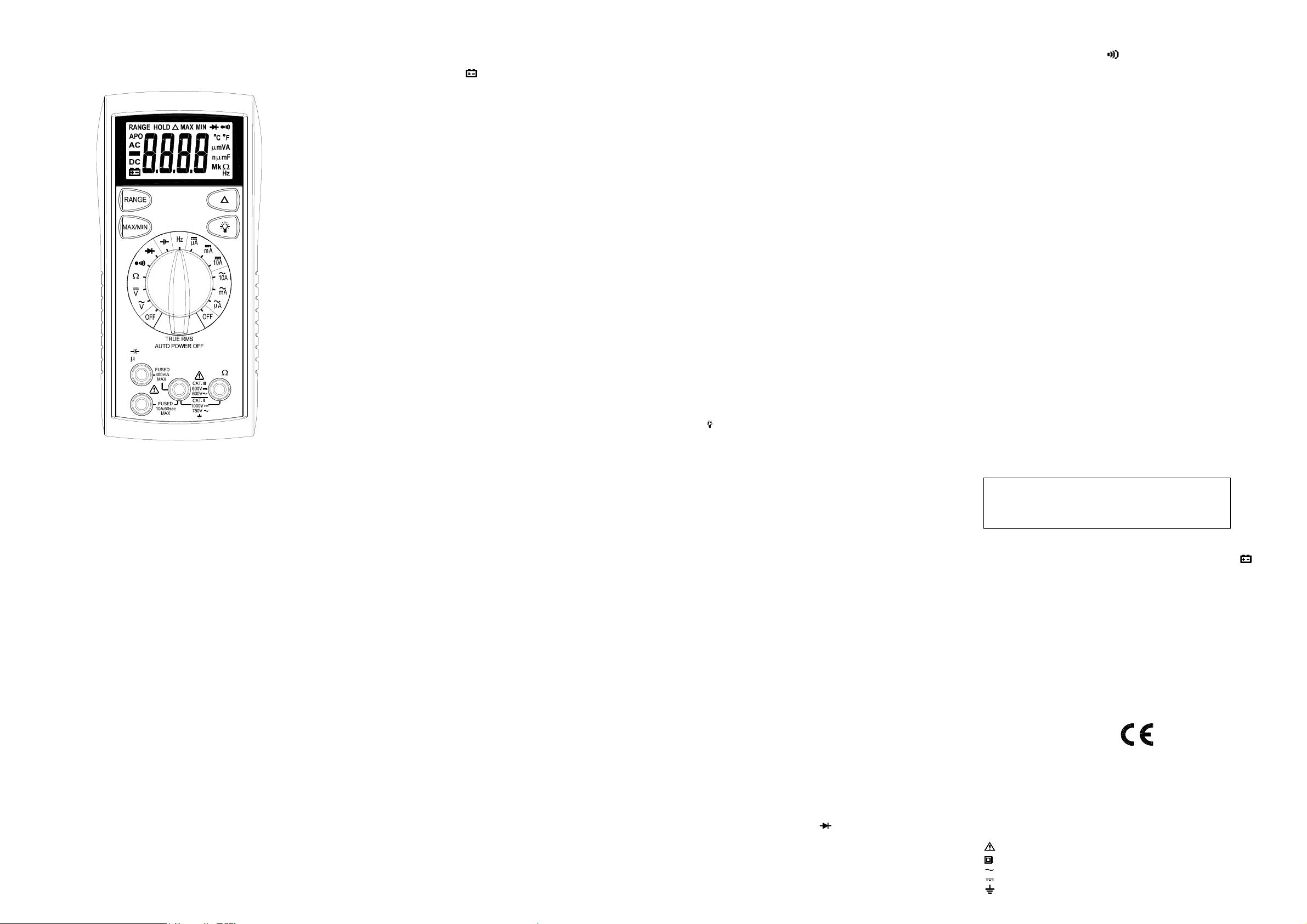
OPERATING INSTRUCTIONS
MODEL 2709B
DIGITAL MULTIMETER
2709B
A mA
COM
10A
SAFETY INFORMATION
The following safetyinformationmustbeobserved to ensure maximum personal
safetyduring the operation at this meter:
Use themeteronly as specifiedinthis manual ortheprotection provided by the
metermight be impaired.
Test themeteronaknown voltagebefore using it to determine if hazardous
voltage is present.
Do not use themeter if the meter or test leads look damaged,orifyoususpect
that themeter is not operating properly.
Neverground yourself when taking electrical measurements.Donottouch
exposed metal pipes,outlets, fixtures, etc., whichmight be at groundpotential.
Keepyour body isolatedfrom ground by usingdry clothing,rubber shoes,rubber
mats,oranyapprovedinsulating material.
Turnoff powerto thecircuit under test before cutting,unsoldering,orbreaking
the circuit. Small amounts of currentcanbedangerous.
Use caution when working above 60V dc or 30V ac rms.Such voltagespose a
shockhazard.
When usingthe probes, keepyour fingers behind the finger guards on the
probes.
Measuring voltagewhich exceedsthelimits of the multimeter may damage the
meterandexpose the operator to a shock hazard. Alwaysrecognizethemeter
voltage limits as stated on the front of themeter.
VHz
SPECIFICATIONS
Display: 3¾ digitliquid crystaldisplay (LCD) withamaximum readingof6600.
Polarity: Automatic, positiveimplied, negative polarityindication.
Overrange: (OL) or (-OL) is displayed.
Zero: Automatic.
Low battery indication: The
belowtheoperatinglevel.
Measurement rate: 2 times persecond, nominal.
Autopower off: Approx. 30minutes.
Operating environment: 0℃ to 50℃ at < 70% relativehumidity.
Storage temperature: -20℃ to 60℃, 0 to 80% relative humidity.
Accuracy: Statedaccuracy at 23℃ ±5℃, < 75% relative humidity.
Temperature Coefficient: 0.1 x (specified accuracy) per ℃. (℃ to 18℃, 28℃ to
50℃).
Altitude: 6561.7 feet (2000m).
Power: Singlestandard 9-voltbattery, NEDA 1604, JIS 006P, IEC 6F22.
Batterylife: 150 hours typical with carbon-zinc.
Dimensions: 165mm(H)x78mm (W) x42.5mm (D).
Weight: Approx. 10.0 oz.(285g)including holster.
Accessories: One set test leads,one spare fuse,9Vbattery (installed), and
Operating Instructions.
is displayed when the battery voltagedrops
" "
DC VOLTS
Ranges: 660mV, 6.6V,66V, 660V, 1000V
Resolution: 0.1mV
Accuracy: ± (0. 5 %rd g+2 dg ts)
Inputimpedance: 660mV:>100MΩ; 6.6V: 10MΩ; 66V ~ 1000V: 9.1MΩ
Overload protection: 1000VDCor750VACrms
AC VOLTS(TRUERMS) (50Hz - 500Hz)
Ranges: 660mV, 6.6V,66V, 660V, 750V
Resolution: 0.1mV
Accuracy: ±(1.5% rdg + 8 dgts) 50 ~60Hz on 660mV range
±( 1.5% rdg + 8 dgts)on 6.6V to 660V ranges
Crestfactor: ≤3
Inputimpedance: 660mV:>100MΩ; 6.6V: 10MΩ;66V ~ 750V:9.1MΩ
Overload protection: 1000VDCor750VACrms
±( 2.0% rdg + 8 dgts)on 750V range
CURRENT
Ranges: 660uA, 6600uA,66mA, 400mA,10A
Resolution: 0.1uA
DC accuracy:
±( 1.5% rdg + 2 dgts) on 660uAto400mAranges
±( 3.0% rdg+ 3 dgts)on10Arange
AC accuracy: (TRUERMS) (50Hz~ 500Hz)
±( 2.0% rdg + 10dgts) on 660uAto 400mAranges
±( 3.5% rdg+ 10dgts) on 10Arange
Crestfactor: ≤3
Voltageburden: 0.4Von660uA, 66mA, 10Aranges
2V on 6600uA, 400mAranges
Inputprotection: 0.5A/500V fastblowceramic fuse
10A/600V fast blow ceramic fuse
10AInput: 10A for60seconds maximum followed
by a 10 minutecooling period
RESISTANCE
Ranges: 660Ω, 6.6kΩ, 66kΩ, 660kΩ, 6.6MΩ, 66MΩ
Resolution: 0.1Ω
Accuracy:
±( 1.2% rdg + 5dgts) on 660Ωto 660kΩranges
±( 2.0% rdg + 5 dgt)on6.6MΩrange
±( 3.5% rdg + 5 dgt) on 66MΩrange
Open circuit volts: -0.45Vdc (-1.2Vdc on660Ωrange)
Overload protection: 500VDC orACrms
CAPACITANCE
Ranges: 6.6nF, 66nF, 660nF,6.6uF, 66uF, 660uF, 6.6mF,66mF
Resolution: 1PF
Accuracy:
±( 3.0% rdg+ 30 dgts)on 6.6nF range
±( 3.0% rdg+ 5 dgts)on66nF to 660uF ranges
±( 5.0% rdg+ 20 dgts)on 6.6mF, 66mF ranges
Overload protection: 500VDC orACrms
FREQUENCY
Ranges: 660Hz, 6.6k,66k,660k, 6.6M,66MHz
Resolution: 0.1Hz
Accuracy: ± (0.1% rdg + 3 dgts)
Sensitivity: 10Hz ~ 6.6MHz:>2.5V rms, 6.6MHz
~ 66MHz:>2.5V rms <5V rms
Minimumpulse width:> 25ns
Dutycycle limits: > 30% and< 70%
Overload protection: 500VDC orACrms
DIODE TEST
Test current: 1.2mA (approximate)
Accuracy: ±(3.0% rdg + 3 dgts)
Resolution: 1mV
Audible indication: <0.03V
Open circuit volts:3.5Vdctypical
Overload protection: 500VDC orACrms
CONTINUITY
Audible indication: Less than 30Ω
Response time: 100ms
Overload protection: 500VDC orACrms
OPERATION
Beforetaking any measurements,read the Safety Information Section.Always
examine the instrument for damage,contamination (excessive dirt, grease,etc.)
and defects. Examinethetest leads forcracked or frayedinsulation.If any
abnormal conditions exist do not attempttomake any measurements.
Input Warning Beeper
The meterhasabeeper that warnstheuser when the test leadisinthecurrent
jack while the meter is switched to make a voltage measurement. Another safety
feature to protect themeterand you.
MAX / MIN
The "MAX" displays themaximum valueof measurements.The "MIN" displays
the minimum value of measurements.The "MAX/MIN"appears and flashes in
the LCDtodisplay thevalue that is beingmeasured now. Afterfinishing the
measurement, pressMAX/MIN button for more than 2 seconds to exit.
Relative Δ
Press (Δ) button to enter the Relative mode. The (Δ) annunciator is displayed,
and residual valueonthedisplay is subtractedandstored as a referencevalue.
In the Relative mode, the valueshown on the displayis always the difference
between the stored reference value and the present reading. Press (Δ) button
againtoexit the relativemode.
Backlight
Pressthe buttontoactivate the backlight for approximately60second.
Manually Selecting Range
The meteralsohas a manual rangemode. In manual range, you select and lock
the meterina range. To manuallyselect a range:
Press[RANGE]button to hold the selected range.Subsequentlypressing the
[RANGE] button willselect each rangeinsequence from the lowest to highest
range. Hold the buttonfor2 seconds to return to theAutorangeMode.
Voltage Measurements
1.Connect the red test lead to”VΩ”jack and the blacktestlead to the ”COM”
jack.
2.SettheFunction/Range switchtothedesired voltage type (AC or DC) and
range. If magnitude of voltage is not known,setswitch to the highestrange
and reduce until a satisfactory readingisobtained.
3.Connect the test leadstothedevice or circuitbeing measured.
4. For dc, a (-) sign is displayed for negativepolarity; positive polarityisimplied.
CurrentMeasurements
1.Connect the red test leadtothe(uA, mA or 10A) jackandthe black test leadto
the "COM" jack.
2.SettheFunction/Range switchtotheDCorAC ranges.
3.Remove power fromthecircuit undertestandopen the normalcircuit path
wherethe measurementistobetaken. Connectthemeter in series withthe
circuit.
4.Apply powerand read the value fromthedisplay.
Resistance Measurements
1.SettheFunction/Range switchtothedesired resistance range.
2.Reove power from the equipment undertest.
3.Connect the redtestlead to the "VΩ"jack and the blacktestlead to the "COM"
jack.
4.Connect the test leadstothepoints of measurements andread the value from
the display.
Diode Tests
1.Connect the red test leadtothe“VΩ” jack and the blacktestleadto
the ”COM” jack.
2.SettheFunction/Range switchtothe“ “ position.
3.Turn offpower to the circuit under test. External voltage across the
components causesinvalid readings.
4.Touchprobes to the diode.A forward-voltage drop is about0.6V(typical for a
silicondiode).
5.Reverse probes.Ifthediode is good, “OL”isdisplayed. If the diodeisshorted,
“000” or another numberis displayed.
6. If the diodeisopen, “OL” is displayed in both directions.
7.Audible Indication: Less than0.03V.
Continuity Measurements
1.SettheFunction switchto the position.
2.Turn off power to the circuitunder test. External Voltage across the
components causesinvalid reading.
3.Connect the test leadstothetwo points at whichcontinuityisto be tested. The
buzzer will sound if the resistance is less thanapproximately 30Ω.
Capacitance Measurements
1.Set the Function/Range switchtothedesired capacitancerange.
2.Connect the red test leadtothe“VΩ” jack and the blacktest lead to the
“COM“jack.
3.Touchtheprobes to the capacitor.Observe polarity when measuring polarized
capacitors.
4.Read the capacitance directly from the display.
5. Discharge the capacitor beforetaking capacitance measurements.
6.Whenthecapacitorto betested is connected, if "dISC" symbolindicates on
LCD,itmeans there is voltageexisting in the tested capacitor and needtobe
discharged beforetesting.
7.Formaximum accuracy,steptothe desiredrangein manualranging, then
press the Relative Δ button to zero out test lead capacitance before the
measurement.
Frequency Measurements
1.Set the Function/Range switchtothe“Hz” position.
2.Connect the redtestleadto the ”VΩ” jackandtheblack test leadto
the ”COM” jack.
3.Connect the testleads to the point of measurement and readthefrequency
fromthedisplay.
Auto Power Off
1.Auto power off:approx. 30 minutes.
2.After auto poweroff, press any buttontorestart the meter, and the reading of
measurement willbemaintainedinthedisplay.
Cancellation of Auto Power Off Feature:
Pressandhold the (RANGE)buttonwhile rotating function switch from off to
any positiontoturn the meter on. The auto powerofffeature is disabled.
Note “APO” annunciator is missingfrom the LCD.
MAINTENANCE
Removetest leads beforechanging battery or fuse or
performing any servicing.
WARNING
Battery Replacement
Poweris suppliedbya9volt battery. (NEDA1604, IEC 6F22). The
on the LCDdisplay when replacement is needed. Toreplace the battery,remove
the threescrews from the backofthemeter and lift offthefront case. Remove
the battery from case bottom.
" "
appears
Fuse Replacement
If no current measurementsarepossible. Checkfor a blown overload protection
fuse.Foraccess to fuses, remove the threescrews from the back of themeter
and liftoff the front case.Replace F1 only withtheoriginal type0.5A/500V, fast
actingceramic fuse,6.35x32mm Replace F2 only with the original type
10A/600V, fast actingceramic fuse,6.35x25.4mm.
Cleaning
Wipe thecasewith a damp cloth andmilddetergent.Donotuseabrasivesor
solvents. Dirt or moisture in the terminalscan affect readings.
Safety: ConformstoIEC61010-1 (EN61010-1),CATII1000V, CATIII 600V, Class
CATII: Is formeasurements performedoncircuits directly connectedto the
CAT III: Is for measurements performed in the building installation.
EMC: Conformsto EN61326.
The symbols used on this instrument are:
II, Pollution degree2Indoor use.
low-voltageinstallation.
Caution, refer to accompanyingdocuments
Equipment protected throughout by Double insulation (ClassII)
Alternating current
Directcurrent
Ground
Page 2

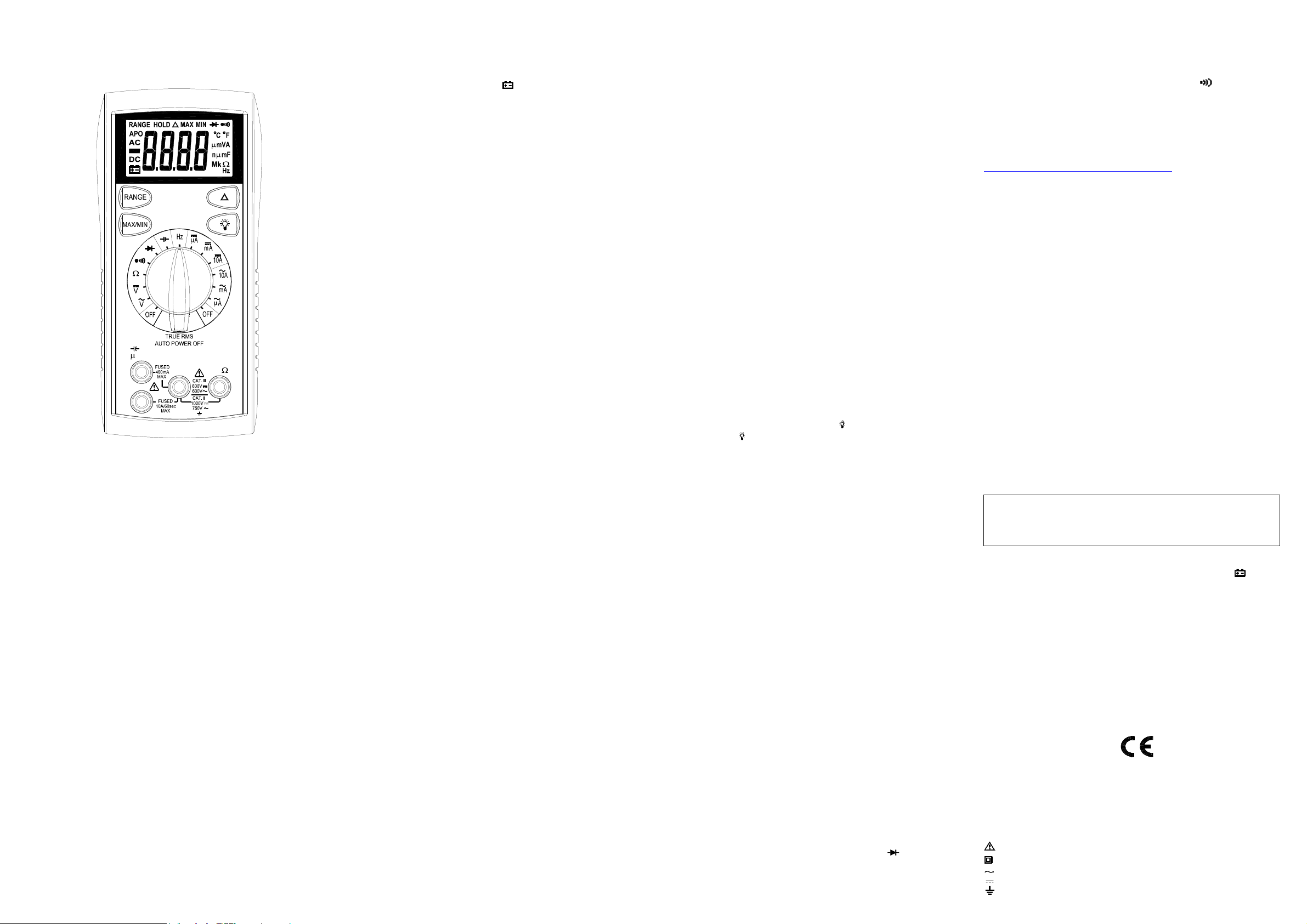
INSTRUCCIONES DE FUNCIONAMIENTO
MODELO 2709B
MULTIMETRO DIGITAL
2709B
A mA
COM
10A
INFORMACION DE SEGURIDAD
La siguiente información relativaalaseguridad debenser observadaspara
garantizar la máximaseguridadpersonal durantelaoperación deestemetro:
Utiliceel medidor sólocomo seespecificaen estemanualolaprotección prevista
en el metropodría verse afectada.
Pruebe dequeel medidoren unvoltaje conocido antes de usarlo paradeterminar
si está presente la tensiónpeligrosos.
Noutilice elmedidorsiel medidoro losconductoresde pruebaparecendañados,
o si sospechaque el medidor no estáfuncionandocorrectamente.
Nuncaestéconectadoa tierra cuando estetomando mediciones eléctricas. No
toquelastuberías de metal expuesto, puntos de venta, accesorios, etc, que
podránestar conectados a tierra.Mantenga su cuerpoaislados de tierra
mediante el uso de ropa seca,zapatos de goma,alfombras de caucho, o
cualquier materialaislante aprobado.
Apague la potenciaal circuitobajo prueba antesdecortar, quitar soldadura, o
romperelcircuito. Pequeñas cantidades de corriente pueden ser peligrosas.
Tengacuidado cuandosetrabaja con mas de 60V de CD o 30 V CA rms.Esas
tensiones planteanun peligro de choque.
Al utilizarlassondas, mantengalos dedos detrásdeldedo de la mano de los
guardias de las sondas.
La medición de tensión queexcede los límitesdelmultímetropuede dañar el
medidor y el operadorse puede de exponer a un peligro de choque. Siempre
reconozcaloslímites de voltajeen el frente del medidor.
ESPECIFICACIONES
Pantalla: 3 ¾ dígitos, pantalla de cristal líquido (LCD) con un máximo de
lectura de 6600.
Polaridad:Automática, positiva implícita, indicación de polaridad negativa.
Sobre Gama: (OL) o (-OL) aparece en pantalla.
Cero: Automático.
Indicación de batería baja: El " " aparece cuando el voltaje de la batería
cae por debajo del nivel de funcionamiento.
Tipo de Medición: 2 veces por segundo, nominal.
Apagado automático: aprox. 30 minutos.
Entorno operativo: 0°C a 50°C a <70% de humedad relativa.
Temperatura de almacenamiento: -20°Ca60°C,de0a80%dehumedad
VHz
relativa.
Precisión: Dicho de precisión a 23°C ± 5°C, <75% de humedad relativa.
Coeficiente de temperatura: 0,1 x (exactitud especificada) por °C. (°C a
18°C, 28°C a 50C°).
Altitud: 6561,7 pies (2000m).
Potencia: El único estándar de la batería de 9 voltios, NEDA 1604, JIS
006P, IEC 6F22.
La duración de la batería: 150 horas típico con carbono-zinc.
Dimensiones: 165mm (H) x78mm (W) x42.5mm (D).
Peso: aprox. 10,0 oz. (285g) incluyendo funda.
Accesorios: Un conjunto conductores de prueba, un fusible de repuesto,
batería de 9V (instalada), y Manual de instrucciones.
VOLTIOS CD
Rangos: 660mV, 6.6V, 66V, 660V, 1000V
Resolución: 0.1mV
Precisión: ± (0.5% lectura + 2dgts)
Impedancia de entrada: 660mV:> 100MΩ; 6.6V: 10MΩ; 66V ~ 1000V:9.1MΩ
Protección de sobrecarga: 1000VCD o 750VCArms
VOLTIOS CA(TRUE RMS) (50Hz - 500Hz)
Rangos: 660mV, 6.6V, 66V, 660V, 750V
Resolución: 0.1mV
Precisión: ±(1.5% lectura + 8dgts) 50 ~ 60Hz en la gama 660mV
±(1.5% lectura + 8dgts) en 6.6V a 660V
±( 2.0% lectura + 8dgts) en la gama 750V
Factor de cresta: ≤3
Impedancia de entrada: 660mV:> 100MΩ; 6.6V: 10MΩ; 66V ~ 750V:
9.1MΩ
Protección de sobrecarga:1000VCD o 750VCA rms
CORRIENT
Rangos: 660uA, 6600uA, 66mA, 400mA, 10A
Resolución: 0.1uA
DC precisión:
±(1.5% lectura + 2dgts) sobre rangos de 660uA a 400mA
±(3.0% lectura + 3dgts) en la gama 10A
Precisión CA: (TRUE RMS) (50Hz ~ 500Hz)
±(2.0% lectura + 10dgts) sobre rangos de 660uA a 400mA
±(3.5% lectura + 10dgts) en la gama 10A
Factor de cresta: ≤3
Tensión de carga: 0.4V en 660uA, 66mA, 10A rangos
6600uA sobre 2V, 400mA rangos
Entrada de protección: 0.5A/500V fusible rápido de cerámica,
10A/600V fusible rápido de cerámica
Entrada de 10A: 10A máximo durante 60 segundos seguidos
Por 10 minutos en un período de enfriamiento
RESISTENCIA
Rangos: 660Ω, 6.6kΩ, 66kΩ, 660kΩ, 6.6MΩ, 66MΩ
Resolución: 0.1Ω
Precisión:
±(12% lectura + 5dgts) sobre 660Ωa 660kΩrangos
±(2.0% lectura + 5dgt) en la gama 6.6MΩ
±(3.5% lectura + 5dgt) en la gama 66MΩ
Voltios circuito abierto:-0.45Vcd (-1.2Vcd gama de 660Ω)
Protección de sobrecarga: 500VCD o CA rms
CAPACITANCE
Rangos: 6.6nF, 66nF, 660nF, 6.6uF, 66uF, 660uF, 6.6mF, 66mF
Resolución: 1pF
Precisión:
±(3.0% lectura + 30dgts) en la gama 6.6nF
±(3.0% lectura + 5dgts) sobre 66nF a rangos 660uF
±(5.0% lectura + 20dgts) sobre 6.6mF, 66mF rangos
Protección de sobrecarga: 500VCD o CArms
±(5.0% lectura + 20dgts) sobre 6.6mF, 66mF rangos
Protección de sobrecarga: 500VCD o CArms
FRECUENCIA
Rangos: 660Hz, 6.6k, 66k, 660k, 6.6M, 66MHz
Resolución: 0.1Hz
Precisión: ± (0.1% lectura + 3dgts)
Sensibilidad: 10Hz ~ 6.6MHz:> 2.5V rms, 6.6MHz
66MHz ~:> 2.5V rms <5V rms
Mínimo ancho de pulso:> 25ns
Ciclo de límites:> 30% y <70%
Protección de sobrecarga: 500VCD o CA rms
PRUEBA de DIODO
Corriente de Prueba: 1.2mA (aproximadamente)
Precisión: ± (3.0% lectura + 3dgts)
Resolución: 1mV
Audible indicación: <0.03V
Voltios circuito abierto: 3.5Vcd típico
Protección de sobrecarga: 500VCD o CA rms
CONTINUIDAD
Indicación audible: Menos de 30Ω
Tiempo de respuesta: 100ms
Protección de sobrecarga: 500VCD o CA rms
OPERACIÓN
Antes de tomar cualquier medida, lea la sección de Información sobre
Seguridad. Siempre examine el instrumento para para daños, la
contaminación (exceso de suciedad, grasa, etc) y defectos. Examine los
conductores de prueba para agrietados o rotos aislamiento. Si alguna de la
condiciones existe no intente realizar las mediciones.
Entrada zumbador de aviso
El medidor tiene un zumbador que avisa al usuario cuando el conductor de
prueba está en el actual jack mientras que el medidor se encuentre conectado
a hacer una medición de tensión. Otra característica de seguridad para
proteger el medidor y usted.
MAX / MIN
El "MAX" muestra el valor máximo de las mediciones. El "MIN" muestra el
valor mínimo de las mediciones. El "MAX / MIN" aparece y parpadea en la
pantalla LCD paramostrarelvalorque se está midiendo ahora. Después de
terminar la medición, pulse MAX / MIN botón durante más de 2 segundos
para salir.
Relativo Δ
(Δ) Pulse el botón para entrar en el modo relativo. El anunciador (Δ) se
muestra, y un valor residual en la pantalla se resta y se almacena como un
valor de referencia. En el modo relativo, el valor que aparece en la pantalla
es siempre la diferencia entre el valor de referencia almacenado y de la
presente lec tura. (Δ) Presione el botón de nuevo para salir del modo
relativo.
Luz de Fondo
Pulse el botón para activar la luz de fondo por aproximadamente 60
segundos.
Seleccionando gama manualmente
El metro también tiene un modo manual de gama. En el manual de gama, que
seleccione así como bloquear el medidor en un rango. Para seleccionar
manualmente un rango:
Pulse el botón [RANGE] para seleccionar el rango apropiado. Posteriormente
presione el botón [RANGE] para seleccionará cada serie en secuencia desde
el más bajo hasta la más alta gama. Mantenga pulsado el botón durante 2
segundos para volver a la modalidad deAutorange.
Las mediciones de Voltaje
1.Conecte el conductor rojo de prueba a la "V Ω"jack y el conductor negro
de prueba a la "COM" jack.
2. Seleccione la Función / Rango de cambio al tipo deseado de voltaje (CA
o CD) y la variedad. Si la magnitud de la tensión no es conocida,
sistemáticamente cambie a una escala mayor y reduzca el rango a una
manera satisfactoria hasta que se obtenga la lectura adecuada.
3. Conecte los conductores de prueba al dispositivo o circuito con que se
mide.
4. Para muestra polaridad negativa, un (-) se demuestra; polaridad positiva
es implicado.
Las mediciones de Corriente
1.Conecte el conductor rojo de prueba a la (tC, mA o 10A) jack y el
conductor negro de prueba a la "COM" jack.
2. Seleccione la Función / Rango para cambiar de los rangos de CD a CA.
3. Elimine el poder del circuito bajo prueba y abra el circuito normal de ruta
donde la medición es que se deben tomar. Conecte el medidor en serie con
el circuito.
4. Aplicar y poder leer el valor de la exhibición.
Mediciones de Resistencia
1. Seleccione la Función / Rango cambiar a la resistencia deseada gama.
2. Elimine el poder de los equipos bajo prueba.
3. Conecte el conductor rojo de prueba a la "V Ω" jack y el conductor negro
de prueba a la "COM" jack.
4. Conecte los conductores de prueba a los puntos de medición y lea el
valor de la exhibición.
Prueba de Diodo
1.Conecte el conductor rojo de prueba a la "V Ω"jack y el conductor negro
de prueba a la "COM" jack.
2. Seleccione la Función / Rango a al posición de "(diode symbol)".
3. Elimine el poder de los equipos bajo prueba. Exteriores voltaje a través
de los componentes causas lecturas no válidas.
4. Toque las sondas al diodo. Una caída de tensión hacia adelante-es de
unos 0.6V (típico para un diodo de silicio).
5. Reverse sondas. Si el diodo es bueno, el "OL" se muestra. Si el diodo
está e n cortocircuito, "000" u otro número aparece en la pantalla.
6. Si el diodo está abierto, el "OL" se muestra en ambas direcciones.
7. Indicación audible: Menos de 0.03V.
Medidas de continuidad
1. Seleccione la Función / Rango a al posición de “ ".
2. Elimine el poder de los equipos bajo prueba. Exteriores voltaje a través
de los componentes causas lecturas no válidas.
3. Conecte los conductores de prueba a los dos puntos en los que la
continuidad es someterse a la prueba. El zumbador sonará si la resistencia
es menor a aproximadamente 30 Ω.
Mediciones de Capacitancia
1. Seleccione la Función / Rango a el rango de capacitancia deseado.
2. Conecte el conductor rojo de prueba a la "V Ω" jack y el conductor negro
de prueba a la "COM" jack.
3. Toque las sondas al condensador. Observe polaridad en la medición de
capacitores polarizados.
4. Leer la capacitancia directamente de la pantalla.
5. Aprobación de la gestión en el condensador antes de tomar mediciones
de la capacitancia.
6. Cuando el capacitador este bajo prueba, si el símbolo "DISC" aparece en
la pantalla, significa que existe un voltaje existente en el capacitador en
prueba y deben ser descargados antes de la prueba.
7. Para precisión máxima, escoja el rango usando el botón “Range”, a
continuación, pulse el botón Δ relativo a cero para llevar a cabo la prueba
antes de la medición.
Las mediciones de frecuencia
1. Establezca la Función / Rango cambiar a la "Hz" posición.
2. Conecte el conductor de prueba rojo a la "V Ω" jack y el conductor negro
de prueba a la "COM" jack.
3. Conectar los conductores de prueba al punto de medida y lea la
frecuencia de la pantalla.
Apagado automático
1. Apagado automático: aprox. 30 minutos.
2. Después de apagado automático, presione cualquier botón para reiniciar
el medidor, y la lectura de la medición se mantendrá en la pantalla.
Cancelación de la función de apagado automático:
Oprime y mantenga oprimido el botón (Range), mientras que mueve la
rotación de función de apagado a cual quier posición. La función de
apagado automático está desactivada.
Nota "APO" anunciador falta en la pantalla LCD
MANTENIMIENTO
ADVERTENCIA
Eliminar conductores de prueba antes de cambiar la batería o
fusible o realización de cualquier servicio.
Reemplazo de baterías
La potencia es suministrada por una batería de 9 voltios. (NEDA 1604, IEC
6F22). El " " aparece en pantalla, cuando el reemplazo es necesario.
Para sustituir la batería, quitar los tres tornillos de la parte posterior del
medidor y el ascensor frente a la parte delantera caso. Extraiga la batería
caso de la parte inferior.
Reemplazo de fusibles
Si lasmedicionesactualesno son posibles. Horas de sopladodefusiblesde
protección de sobrecarga. Para el acceso a los fusibles, quitar los tres
tornillos de la parte posterior del medidor y el ascensor frente a la parte
delantera caso. Sustituir F1 sólo con el tipo original 0.5A/500V, actuando
rápida de fusibles de cerámica, 6.35x32mm.
Sustituir F2sóloconeloriginal10A/600V tipo, que actúan rápidodefusibles
de cerámica, 6.35x25.4mm.
Limpieza
Limpie el caso con un paño húmedo y detergente suave. No utilice
productos abrasivos o disolventes. La humedad o la suciedad en los
terminales pueden afectar a las lecturas.
Seguridad:Se ajusta a IEC61010-1 (EN61010-1), CATII 1000V, CATIII
600 V, clase II, grado de contaminación 2 Salas de uso.
CATII: Es para las mediciones realizadas en los circuitos conectados
directamente a la instalación de baja tensión
CAT III: Es para las mediciones realizadas en la construcción de la
instalación.
EMC: Se ajusta a EN61326.
Los símbolos utilizados en este instrumento son:
Precaución, refiérase a los documentos que la acompañan
Equipo protegido en todo momento por doble aislamiento (clase II)
Corriente alterna
Corriente
Tierra
Page 3

Manuel d’utilisation
Il est impératif de débrancher les cordons avant toute opération de
Modèle 2709B
Multimètre Numérique 6600 points TRMS
2709B
A mA
COM
10A
PRESCRIPTIONS DE SECURITE
Les prescriptionsdesécurité ci dessous sont à suivre scrupuleusementafin de
garantir la sécuritédel’utilisateur:
N’utiliservotre appareil que dans le domaine d’utilisationdéfini dans ce manuel.
Danslecascontraire les protections pourraientêtreendommagées.
Toujours tester votreappareil surunetension connueavant de l’utiliserpour une
mesurede tension.
Ne pas utiliservotre appareil o uses cordons voussemblent endommagés.
Ne jamaisvous mettre à la terrelorsque vous faitesdesmesures de tension. Ne
jamaistoucher des parties métalliques qui pourraient êtrereliées à la terre lors
d’unemesure. Dans la mesuredupossible, isolez-vousdelaterre par des
chaussures, vêtements ou gantsappropriés.
Pensezà couper le courant avantd’ouvrir un circuitoud’intervenir sur celui-ci.
Mêmeunfaible potentielpeut être dangereux.
Prenez toutes les précautions nécessaires lorsque vous intervenez sur des
tensions supérieures à 60V DC ou 30VACeff.
Lorsque vous utilisezdes pointes de touche, ne jamais mettrelesdoigts au delà
des anneaux de garde.
Mesurer des tensionsougrandeurs au delàdes limites de l’appareil peut
endommager les protections, endommager votreappareilet mettre en danger la
sécurité de l’utilisateur.Assurezvousdeconnaîtreleslimites de votre appareil,
avantutilisation.
VHz
SPECIFICATIONS
Affichage: 3 3/4 digits(LCD) avec un affichagede6600 maximum
Polarité:Automatique,avecindicationdusigne moins.
Dépassement: (OL)ou(-OL) est affiché.
Zéro:Automatique.
Indication de pile usée:lesymbole
qu’ilfaut la remplacée.
Cadence de mesure: 2 fois/s(typique)
Arrêtautomatique:après environ 30 minutes.
Température de fonctionnement:0℃ à 50℃ avec HR < 70%.
Température de stockage: -20℃ à 60℃, HR de 0 à 80%.
Précision: donnéeà23℃ ±5℃, HR < 75%.
Coefficient de température:0.1x(précision)par ℃. (℃ < 18℃,etde28℃ à
50℃).
Altitude: utilisation jusqu’à2000m.
Alimentation:pile9 V type NEDA1604, JIS 006P,IEC6F22.
Autonomie: 150 heures typique.
Dimensions: 165mm(H)x78mm (W) x 42.5mm (D).
Masse:environ 285gavec gaine
Accessoires: jeu decordons, fusiblederechange,pile(9V) installée, manuel.
est affiché lorsquela pileestusée et
" "
TENSIONS DC
Gammes: 660mV, 6.6V,66V, 660V, 1000V
Résolution: 0.1mV
Précision: ± (0. 5 %rd g+2 dgts)
Impédance d’entrée: 660mV:>100MΩ; 6.6V:10MΩ; 66V ~ 1000V: 9.1MΩ
Protection: 1000VDCou 750VAC eff.
TENSIONSAC(TRUE RMS) (50Hz - 500Hz)
Gammes: 660mV, 6.6V,66V, 660V, 750V
Résolution: 0.1mV
Précision: ±(1.5% +8 dgts) 50~60Hzsur gamme 660mV
±( 1.5% + 8 dgts)sur6.6V et 660V
Facteur de crête: ≤3
Impédance d’entrée: 660mV: >100MΩ; 6.6V:10MΩ; 66V ~ 750V:9.1MΩ
Protection:1000VDC ou 750VACeff.
±( 2.0% rdg + 8 dgts)sur 750V
COURANTSAC ET DC
Gammes: 660uA, 6600uA, 66mA,400mA, 10A
Résolution: 0.1uA
Précision en DC:
±( 1.5% + 2 dgts) de 660µAà 400mA
±( 3.0% + 3 dgts)sur10A
Précision en AC: (TRUE RMS) (50Hz~500Hz)
±( 2.0% + 10 dgts)de 660µA à 400mA
±( 3.5% +10 dgts)sur 10A
Crestfactor: ≤3
Chutedetension: 0.4V sur 660µA, 66mA,10A
2V sur 6600uAet400mA
Protection: fusibleF0.5A/500V (céramique rapide)
Fusible F10A/600V(céramiquerapide)
Entrée10A: 10Apendant 60 secondes maximumsuivi d’une périodesans
courant de 10minutesminimum
RESISTANCE
Gammes: 660Ω, 6.6kΩ, 66kΩ,660kΩ, 6.6MΩ, 66MΩ
Résolution: 0.1Ω
Précision:
±( 1.2% + 5dgts) de 660Ωà 660kΩ
±( 2.0% + 5 dgt) sur6.6MΩ
±( 3.5% + 5 dgt) sur 66MΩ
Tension en circuit ouvert: -0.45Vdc (-1.2Vdc sur 660Ω)
Protection: 500VDC ou AC eff.
MESURES DE CAPACITE
Gammes: 6.6nF, 66nF, 660nF,6.6uF, 66uF, 660uF,6.6mF, 66mF
Résolution: 1pF
Précision:
±( 3.0% + 30 dgts)sur6.6nF
±( 3.0% + 5 dgts)de66nFà660uF
±( 5.0% + 20 dgts)sur6.6mF, 66mF
Protection: 500VDC ou AC eff.
FREQUENCE
Gammes: 660Hz, 6.6k,66k, 660k, 6.6M,66MHz
Résolution: 0.1Hz
Précision: ± (0.1% + 3 dgts)
Sensibilité: 10Hz ~ 6.6MHz:>2.5V eff., 6.6MHz
~ 66MHz:>2.5V rms <5V eff.
Largeur d’impulsionmini: > 25ns
Rapport cycliquemini: > 30%et< 70%
Protection: 500VDC ou AC eff.
TEST DIODE
Courant de test: 1.2mA (typique)
Précision: ±(3.0%+3 dgts)
Résolution: 1mV
Indication sonore: <0.03V
Tension en circuit ouvert: 3.5Vdc typique
Protection: 500VDC ouACeff.
CONTINUITE
Indication sonore: pourR<30Ω
Temps de réponse: 100ms
Protection: 500VDC ouACeff.
MISE EN OEUVRE
Avant toute mesure, assurez-vous d’avoirpris connaissance des Prescriptions
de Sécurité. Toujoursvérifier quel’appareil et sescordons ne sont pas
endommagés. Si vousavez le moindre doute,nepas effectuerdemesure.
Alerte sonore pour cordons mal positionnés
Le multimètredispose d’unealarme sonoresi vousavez un cordon branché
danslaborne mAouAetsilecommutateur est surunemesure detension. Dans
ce cas vérifiez impérativement le branchement.
MAX / MIN
Appuyer plusieursfois sur la touche MAX/MIN: le symbole "MAX"signifie que la
valeurMAX est affichée,lesymbole MIN signifie que la valeurMINestaffichée.
Un affichage de MAX/MIN clignotantindique quelavaleur affichéeestlavaleur
courante.
Appuyer plus de 2s pour sortirdelafonction MAX/MIN.
Mode RELATIF - Δ
Appuyer sur la touche (Δ) pour activer le moderelatif. Le symbole(Δ) est alors
affiché et la valeur mémorisée lors de l’appui est soustraiteàlamesure. En
mode Relatif, la valeuraffichée esttoujours la différence entrelavaleurmesurée
et la valeur de référencemémorisée..Appuyer de nouveau sur la touche (Δ)
pourquitter le mode Relatif.
Rétro-éclairage
Appuyer sur pour avoir un retro-éclairageduLCDpendant environ60
secondes.
Utilisation en gammes manuelles
Le multimètre peut être utilisé en gammes manuelles, ce qui peut êtretrès
pratique pour certaines applications. Pour cela:
Appuyer sur la touche [RANGE] afin de figer la gamme.D’autres appuisur
[RANGE] feront défilerles gammes dans le senscroissant.Pour repasser en
mode automatique,appuyer sur [RANGE] pendant plusde2s.
Mesures de tension
1. Brancher le cordon rouge à la borne ”VΩ” et le cordon noir à la borne”COM”.
2. Positionner le commutateur sur la fonction appropriée DC ouAC.
3. Brancher les cordonssurvotre application.
4. Lirele résultat sur l’afficheur LCD.Lapolarité est indiquée avec le signe (-)en
DC
Mesures de courant
1. Brancher le cordon rougeà la borneµA/mAou 10A, et le cordonnoir à la
borne”COM”.
2. Positionner le commutateur sur la gammeappropriée en DC ou AC.
3.Assurez-vous que le circuit à mesureresthors tension et branchezvos
cordons en série dans ce circuit.
4. Mettresous tension et lirelecourant sur l’afficheur LCD
Mesures de résistance
1. Positionner le commutateur rotatif sur la fonctionΩ
2.Assurez-vous que le dispositifà mesurer soit hors tension.
3. Brancher le cordon rougeà la borne”VΩ” et le cordonnoir à la borne ”COM”.
4. Branchez les cordonsà votre applicationoutester par contact avec les
pointes de touche.
Test Diode
1. Brancher le cordon rouge à la borne ”VΩ” et le cordon noir à la borne”COM”.
2. Positionner le commutateur sur “ “.
3.Assurez-vous que le dispositifà mesurer soit hors tension, afin de ne pas
fausserla mesure.
4. Testerladiode à l’aide des pointes de touché: le sens passant d’unediode
silicium fait apparaitre une tension de 0.6V (typique)
5. Une diodeouverte ou sens bloqué se traduiraparunaffichage“OL”. Une
diodeencourt-circuitse traduira par un affichage “000”ouproche de 0.
6. Remarque: unediode ouvertedonne un affichage “OL” dans les 2 sens
7. Signalsonore pourunetension < 0.03V.
Test de continuité
1. Positionner le commutateur sur
2.Assurez-vous que le dispositifà mesurer soit hors tension, afin de ne pas
fausserla mesure.
3. Branchez les cordonsàvotre applicationou tester par contact avec les
pointes de touche. Le buzzer est actif pour R<30ohms.
Mesures de capacité
1.Positionnerlecommutateursur la gamme désirée(marquageF)
2. Brancher le cordon rougeà la borne“F“ et le cordon noirà la borne”COM”.
3. Se brancher aux bornesducondensateuràl’aide des pointesdetouche
4.Lire la valeur directement sur l’afficheur
5. Ne fairelesmesures que sur descondensateurs déchargés.
6. Si le condensateur mesuréest ouvert ou si celui si est chargé, l’afficheur
indiquera "dISC".Ilfautvérifiervotrecomposantà tester.
7. Pourunemeilleure précision sur les gammesbasses, il est recommandé
d’utiliser le mode Relatif(toucheΔ)afin d’éliminerlescapacitésparasites.
Mesures de fréquence
1. Positionner le commutateur sur ”Hz”
2. Brancherlecordon rouge à la borne”VΩ” et le cordon noir à la borne ”COM”.
3. Brancher sur votre applicationet lirela fréquence sur l’afficheur. Le
changement de gammeestautomatique.
Arrêt automatique
1.Après environ30 minutes.
2.Après un arrêt automatique, un appui sur une touchéouuneremiseen
marchepar le commutateur permet uneremise en fonctionnement normal.
Inhibition de l’arrêt automatique:
Appuyer sur la touche (RANGE) à la mise en marche de l’appareil.L’arrêt
automatique est alorsinhibé.
Remarque :lesymbole “APO” n’apparaitplusàl’affichage.
MAINTENANCE
ATTENTION- DANGER
maintenance – Risque de choc électrique.
Remplacement de la pile
Votre multimètre utiliseune pile 9V. (NEDA1604,IEC6F22). Lorsque le symbole
" " apparait à l’affichage il faut remplacer la pile.Assurez-vous d’avoir
débranché les cordons. Dévisserle fonddeboitier et remplacer la pile. Revisser
le fonddeboitier.
Remplacement des fusibles
Si les mesures de courant ne fonctionnentpas, il faut vérifierl’état des fusibles
qui assurent la protection de votre multimètre.
les cordons. Dévisserlefond de boitier et vérifier les fusibles :
F1 0.5A/500V, type céramique F (rapide),6.35x32mm.
F2 10A/600V,type céramiqueF(rapide), 6.35x25.4mm.
Attention : Ne remplacer les fusibles qu’aveclemême type.
Assurez-vous d’avoirdébranché
Nettoyage
Nettoyer périodiquement avecunchiffon doux et humide. Ne pas utiliserde
solvants. Saletéet/ouhumidité auniveau des douillespeuvent perturber les
mesures et donner des indications fausses.
Sécurité: IEC61010-1 (EN61010-1),CATII 1000V, CATIII600V,Class II, Degré
de pollution 2, utilisationàl’intérieur.
CATII / CAT III : se reporter aux normes pour la définition des catégories
d’installation
EMI: selonEN61326.
Symboles utiliséssur l’appareil:
Attention– Danger:se référer au manuel
Double isolement(Classe II)
Courant alternatif
Courant continu
Terre
Page 4
BEDIENUNGSANLEITUNG
DIGITAL-MULTIMETER
MODELL 2709B
2709B
A mA
COM
10A
SICHERHEITSINFORMATIONEN
Um ein Maximum an persönlicher Sicherheit beim Betriebdieses Multimeters zu
gewährleisten,bitte unbedingt folgendeSicherheitshinweisebeachten:
Das Gerät nur nach der in dieserBedienungsanleitungangegebenenSpezifikationverwenden.Ansonstenkönnen die im Messinstrumentvorhandenen
Schutzmechanismen außer Kraftgesetzt sein.
TestenSiedasMultimeterzuerst mit einerbekannten Spannung,bevor Sie es
dafürverwenden,dasVorhandensein vongefährlichenSpannungen zu über-
prüfen.
Das Multimeter nicht verwenden,wenndas Instrumentoder die PrüfkabelBe-
schädigungenaufweisen oder wennSieden Eindruck haben, dass das Gerät
nichtordnungsgemäß funktioniert.
Bei DurchführungelektrischerMessungenkeine Erdung zum eigenen Körper
herstellen. Niemalsoffen liegende, blankeKabel, Ausgänge,Anschlüsse,Vorrichtungen, Halterungenberühren, um jeglichenKontaktmitErdpotential zu vermeiden. Sorgen Sie dafür, dass Ihr Körpervon der Erde isoliertbleibt, indem Sie
trockene Kleidung, Gummischuhe, Gummimatten oder andereszugelassenes
Isolierungsmaterial verwenden.
Schalten Sie denzu prüfenden Schaltkreis zuerststromlos,bevorSieihn trennen,
ablöten oder unterbrechen.Auch geringeStrommengenkönnen gefährlich sein.
SeienSie besonders vorsichtig,wenn SiemitSpannungenarbeiten,dieüber60V
Gleichstrom oder30VWechselstromEffektivwert (rms) liegen.Spannungen in
dieserHöhe lösen elektrische Schläge aus.
Beim Umgang mit den Prüfspitzen die Finger bitte stets hinterder Abschirmung
des Isoliergriffshalten.
DieMessung von Spannungen, die die Grenzwerte desMultimetersübersteigen,
kanndasGerät beschädigen und den Bediener der Gefahreines Stromschlags
aussetzen. Beachten Sie bitte stetsdieauf der Vorderseite des Geräts
angegebenen Spannungsgrenzwerte.
Hz
V
TECHNISCHE DATEN
Display: 3¾-stelligeFlüssigkristallanzeige (LCD) mit max. 6600Zählimpulsen.
Polarität: Automatisch, positive Polarität implizit,negative wirdangezeigt.
Bereichsüberschreitung: Anzeigevon (OL) oder (-OL).
Null:Automatisch
Indikator bei schwacher Batteriespannung: SinktdieBatteriespannungunter
das Betriebsniveau, wird das Symbol
Messrate: Nennwert 2 Mal pro Sekunde.
AutomatischeAbschaltung: nach ca. 30 Minuten Inaktivität
Betriebsumgebung: 0℃ bis 50℃ bei einerrelativen Feuchtigkeit < 70%.
Lagertemperatur: -20℃ bis 60℃, 0 bis 80% relativeFeuchtigkeit.
Genauigkeit:Angabengelten für 23℃ ±5℃ und einerrelativenFeuchte < 75%.
Temperaturkoeffizient:0,1x(spezifizierte Genauigkeit) pro ℃. (℃ bis 18℃, 28
℃ bis 50℃).
Maximale Höhenlagefür den Betrieb: 2000m.
Stromversorgung: 9-Volt-Bockbatterie, TypNEDA1604, JIS 006P, IEC 6F22.
Batterielebensdauer: 150 Stunden typisch fürKohle-Zink.
Abmessungen: 165 mm (H) x 78 mm (B) x 42,5 mm (T).
Gewicht: ca. 285 g inkl. Holster.
Zubehör: 1 Satz Prüfkabel, 1 Stk. Ersatzsicherung, 9 V-Batterie(eingelegt)und
Bedienungsanleitung.
GLEICHSPANNUNG
Bereiche: 660 mV; 6,6 V;66V;660 V; 1000V.
Auflösung: 0,1 mV
Genauigkeit: ± (0,5% des Messwerts + 2 Stellen)
Eingangsimpedanz:660 mV: >100MΩ; 6,6V:10MΩ; 66 V ~ 1000 V: 9,1MΩ
Überlastschutz: 1000 VDCoder 750 VACEffektivwert
WECHSELSPANNUNG (echte Effektivwerte)(50 Hz - 500 Hz)
Bereiche: 660 mV; 6,6 V;66V;660 V; 750 V.
Auflösung: 0,1 mV
Genauigkeit:
±( 1,5% des Messwerts + 8 Stellen) 50 ~ 60 Hz im 660 mV-Bereich
±( 1,5% des Messwerts + 8 Stellen)indenBereichen6,6V bis 660V
±( 2,0% des Messwerts + 8 Stellen)im 750V-Bereich
Scheitelfaktor: ≤3
Eingangsimpedanz: 660 mV: >100 MΩ; 6,6 V:10MΩ; 66 V ~ 750 V: 9,1 MΩ
Überlastschutz: 1000 VDC oder750VAC Effektivwert
STROM
Bereiche: 660 µA, 6600 µA, 66 mA, 400mA,10A
Auflösung: 0,1 µA
Genauigkeit Gleichstrom:
±( 1,5% des Messwerts + 2 Stellen)indenBereichen660µAbis 400 mA
±( 3,0% des Messwerts + 3 Stellen)im 10A-Bereich
Genauigkeit Wechselstrom: (echte Effektivwerte)(50Hz~500Hz)
±( 2,0% des Messwerts + 10Stellen) in den Bereichen 660 µA bis 400mA
±( 3,5% des Messwerts + 10Stellen) im 10 A-Bereich
Scheitelfaktor: ≤3
Spannungsbürde: 0,4 V in den Bereichen 660 µA, 66 mA, 10A
2 V in den Bereichen 6600 µA, 400 mA
Eingangsschutz: FlinkeKeramiksicherung0,5A / 500 V
FlinkeKeramiksicherung 10A / 600 V
10 A-Eingang: 10A für 60 SekundenMaximum gefolgtvon einer
Abkühlphase von10 Minuten
WIDERSTAND
Bereiche: 660 Ω, 6,6 kΩ, 66 kΩ, 660 kΩ, 6,6 MΩ, 66 MΩ
Auflösung: 0,1 Ω
Genauigkeit:
±( 1,2% des Messwerts + 5 Stellen)indenBereichenvon660Ωbis660 kΩ
±( 2,0% des Messwerts + 5 Stellen)im 6,6MΩ-Bereich
±( 3,5% des Messwerts + 5 Stellen)im 6,6MΩ-Bereich
Leerlaufspannung: -0,45 VDC (-1,2 VDCim Bereich 660 Ω)
Überlastschutz: 500 VDC oderAC Effektivwert
KAPAZITÄT
Bereiche: 6,6 nF,66nF,660nF,6,6µF,66µF,660µF,6,6mF,66mF
Auflösung: 1 pF
Genauigkeit:
±( 3,0% des Messwerts + 30Stellen) im 6,6 nF-Bereich
±( 3,0% des Messwerts + 5 Stellen)indenBereichen66nFbis660µF
±( 5,0% des Messwerts + 20Stellen) in den Bereichen 6,6 mF,66 mF
Überlastschutz: 500 VDC oderAC Effektivwert
FREQUENZ
Bereiche:660 Hz, 6,6 kHz, 66 kHz, 660 kHz,6,6MHz, 66 MHz
Auflösung: 0,1 Hz
Genauigkeit: ± (0,1%des Messwerts+3Stellen)
Empfindlichkeit: 10 Hz ~ 6,6 MHz:>2,5Veff, 6,6 MHz
~ 66 MHz:>2,5Veff.<5Veff.
MinimumImpulsbreite: > 25 ns
Tastverhältnis (Duty Cycle)-Grenzen: > 30% und< 70%
Überlastschutz: 500 VDC oderAC Effektivwert
angezeigt.
DIODENTESTS
Prüfstrom: 1,2 mA(ungefähr)
Genauigkeit:±( 3,0%desMesswerts+3 Stellen)
Auflösung: 1 mV
Signalton bei: <0,03 V
Leerlaufspannung: 3,5 VDCtypisch
Überlastschutz: 500VDCoder AC Effektivwert
DURCHGANGSPRÜFUNG
Signalton bei: unter 30Ω.
Reaktionszeit: 100ms
Überlastschutz: 500VDCoder AC Effektivwert
FUNKTIONSBESCHREIBUNG / BETRIEB
BevorSieMessungendurchführen,lesen Sie bitte denAbschnittSicherheitsinformationen.ÜberprüfenSiedas Instrumentstets auf Beschädigungen,
Schmutz (übermäßige Verschmutzungen, Fettusw.) und Defekte. Überprüfen
Sie die IsolierungderMessleitungen auf Risse oderAbnutzungserscheinungen.
Das Messgerät auf keinenFallverwenden,wenn irgendwelche ungewöhnliche
Bedingungen vorliegen.
Akustisches Warnsignal bei falscher Buchsenbelegung
DasMessgerätverfügt übereinen Summer, der denBenutzer warnt, wenn sich
die Messleitung in derStrombuchse befindetunddas Gerät zur Spannungsmessungeingestelltist.Dasist ein zusätzliches Sicherheitsmerkmal für Ihre
Sicherheit und zum Schutzdes Geräts.
MAX / MIN
Bei „MAX“ wird der Maximalwert der Messungangezeigt.Bei„MIN“ ist der
MinimumwertderMessungenabzulesen. "MAX/MIN" erscheint auf dem LCD
und blinkt, um den Wert anzuzeigen, dergerade gemessenwird. Nach
Beendigung der Messung drückenSiedieMAX/MIN-Taste längerals 2
Sekunden, um den Moduszuverlassen.
Relativ-Modus – Taste ∆
Um in den BetriebsmodusRelativ ∆ zu gelangen, drücken Sie die Taste ∆. Der
Indikator ∆ wird angezeigt und das auf dem Display angezeigt e Ergebnis wird
subtrahiertundals Referenzwertgespeichert.Im Betriebsmodus‚Relativ’ist der
auf dem Display angezeigte Wert immerdieDifferenzzwischen dem gespei-
cherten Referenzwertund dem momentanenErgebnis.DrückenSiedie Taste∆
erneut, um den Relativ-Modus zu verlassen.
Hintergrundbeleuchtung – Taste
Drücken der Taste aktiviert für ca. 60 Sekunden die Hintergrundbeleuchtung.
Manuelle Bereichswahl – Taste [Range]
Das Gerät verfügt auchübereinen Modus zur manuellen Bereichswahl. Bei der
manuellen Bereichswahl wählenSie denBereich und legendiesen für die
Messungen des Geräts fest. So wählenSieeinen Bereich manuell:
DieTaste[RANGE] drücken, um den ausgewählen Bereichfestzulegen.Durch
nachfolgendesDrücken der Taste [RANGE] wird nacheinanderjederBereich
vom kleinsten zum größtenBereich ausgewählt. Halten Sie die Taste [RANGE]
für 2 Sekunden gedrückt, um in den Modusderautomatischen Bereichswahl
zurückzukehren.
Spannungsmessungen
1.Die rote MessleitungandieBuchse „VΩ” und die schwarze Messleitung an die
Buchse„COM“ anschließen.
2.Den Funktions-/Bereichswahlschalter auf den gewünschten Spannungstyp
(AC oderDC)und den Bereich einstellen. Ist dieGröße der Spannung nicht
bekannt, denSchalteraufden größten Bereicheinstellenund dannreduzieren,
bis ein zufriedenstellenderMesswert erreicht ist.
3.Die Messleitungenandas zu messende Gerät oderden zu messenden Schaltkreisanschließen.
4.Für Gleichspannung(DC) wird fürnegativePolarität dasZeichen (-) angezeigt;
positive Polaritätistimplizit.
Strommessungen
1.Die rote Messleitung an die Buchse„uA,mA oder 10A”unddieschwarze
Messleitung an die Buchse„COM“ anschließen.
2.Den Funktions-/Bereichswahlschalter auf den BereichAC oder DC einstellen.
3. Stromversorgung des zu messenden Schaltkreises abschalten und die
normale Leiterbahn öffnen,anderdieMessung vorgenommen werdensoll.
Das Multimeter mit dem Schaltkreisin Reihe schalten.
4. Den Strom einschalten und den Wertaufdem Display ablesen.
Widerstandsmessungen
1. Den Funktions-/Bereichswahlschalter auf den gewünschten
Widerstandsbereich einstellen.
2.Die Stromquelle des zu messenden Geräts abschalten.
3.Die rote Messleitung an die Buchse „VΩ“ und die schwarze Messleitung an
die Buchse „COM“ anschließen.
4.Die Messleitungen an die Messpunkte anschließen und denWertvomDisplay
ablesen.
Diodentests
1.Die rote Messleitung an die Buchse „VΩ“ und die schwarze Messleitung an
die Buchse „COM“ anschließen.
2.Den Funktions-/Bereichswahlschalter auf die Position einstellen.
3.Die Stromquelle des zu messenden Schaltkreises abschalten. Externe
Spannungenum die Komponentenherum führenzufehlerhaftenMesswerten.
4.Die Diode mit den Prüfspitzen berühren. Der Vorwärts-Spannungsabfallliegt
bei ca. 0,6V (typisch für eine Silikon-Diode).
5.Prüfspitzenvertauschen. Wenn die Diode in Ordnung ist, wird „OL“ angezeigt.Istdie Diodekurzgeschlossen, wird„000“ oder eine andere Zahl
angezeigt.
6. Ist die Diodeoffen, wird„OL“inbeiden Richtungen angezeigt.
7. Signalton bei: unter0,03 V.
Durchgangsprüfungen
1. Den Funktions-/Bereichswahlschalter auf die Position “ “ einstellen.
2.Die Stromversorgungdes zu messendenSchaltkreisesabschalten.Externe
Spannungenum die Komponentenherum führen zu einemfehlerhaften
Messergebnis.
3.Die Messleitungen an die beidenMesspunkte anschließen,andenen der
Durchgang zu prüfenist.Der Summerertönt, wennder Widerstandunter
einemWert von ca. 30 Ωliegt.
Kapazitätsmessungen
DenKondensatorbitte vor der Messungentladen!
1.Den Funktions-/Bereichswahlschalter auf den gewünschten Kapazitätsbereich
einstellen.
2.Dierote Messleitung an dieBuchse „VΩ“ und dieschwarze Messleitungandie
Buchse„COM“ anschließen.
3.Den Kondensator mit den Prüfspitzen berühren. Bei der Messungvon
polarisiertenKondensatoren bitte auf die Polarität achten.
4.Die Kapazität direkt auf dem Display ablesen.
6.WirdbeiAnschluss des zu prüfendenKondensators auf dem Displaydas
Symbol„dISC" angezeigt, bedeutet dies, dass im Kondensator Spannung
vorhanden ist.
7.Für eine maximaleGenauigkeit gehen Sie über diemanuelle Bereichswahl
zum gewünschtenBereich und drückendann die Taste ∆, um vor der
Messung die Kapazität der Messleitungen zu eliminieren.
Frequenzmessungen
1.Den Funktions-/Bereichswahlschalter auf die Position „Hz“einstellen.
2.Dierote Messleitung an die Buchse „VΩ“ und die schwarze Messleitung
an die Buchse„COM“ anschließen.
3.Die Messleitungen an die Messpunkte anschließen und den
FrequenzwertaufdemDisplay ablesen.
Automatische Abschaltung
1. Automatische Abschaltung:nachca. 30 Minuten Inaktivität
2. Zum StartdesMultimetersnach einer automatischenAbschaltung eine
beliebige Taste drücken und der Messwert bleibt aufdem Display
erhalten.
Automatische Abschaltung deaktivieren:
DieTaste[Range] gedrückt haltenunddenFunktions-/Bereichswahlschalter von
OFF zu einerbeliebigenPosition drehen, um das Multimeter einzuschalten. Die
Funktion der automatischenAbschaltung ist jetzt deaktiviert.
Hinweis: DerIndikator „APO“(AutoPower Off)wirdnicht mehr auf dem Display
angezeigt.
WARTUNG
WARNHINWEIS
Vor dem Austausch der Batterie oder der Sicherungen oder anderen
Wartungsarbeiten bitteunbedingt die Messleitungenabstecken!
Austausch der Batterie
DasGerät wird von einer 9 Voltgespeist (NEDA1604, IEC 6F22). Wenn ein
Austausch erforderlich ist, erscheint auf dem Display das Symbol . Zum
Batteriewechselentfernen Sie aufder Rückseitedes Geräts diedrei Schrauben undnehmen das vordereGehäuseteilab.Entnehmen Siedann die
Batterie aus dem Unterteil des Geräts.
Austausch von Sicherungen
Wennkeine Strommessungenmöglich sind, überprüfenSie,obdieSicherungenfür den Überlastschutzdefekt sind.Zum Austausch derSicherungen
diedrei Schraubenauf der Rückseitedes Gerätsentfernen unddasvordere
Gehäuseteil abnehmen. Die Sicherung F1 nur mit eineroriginalen,flinken
Keramik-Sicherung desTyps 0,5A/500 V,6,35 x 32 mm unddieSicherung
F2 nur mit eineroriginalen,flinken Keramik-Sicherung des Typs 10A/600 V,
6,35 x 25,4mm ersetzen.
Reinigung
Gehäuse mit einem feuchten Tuchundmildem Reiniger abwischen. Keine
Scheuer- oder Lösungsmittel verwenden. Schmutzoder Feuchtigkeit an den
Klemmenkann zu fehlerhaften Messergebnissenführen.
Sicherheit: ErfülltdieNormen IEC61010-1(EN61010-1), CATII 1000V, CATIII
600V, KlasseII, Verschmutzungsgrad 2 zur Verwendung in
Innenräumen.
CATII: Gilt für Messungen an Schaltkreisen, die direkt mit eine
Niederspannungseinrichtung verbunden sind.
CAT III: Gilt für Messungen an Gerätenin Festinstallationen in Gebäuden.
EMV: Erfüllt die Norm EN61326.
Folgende Symbole finden Sie auf dem Gerät:
Vorsicht! BitteSicherheitshinweise in beiliegenden Dokumenten beachten.
Gerätdurchgängiggeschützt durchdoppelteIsolierung (KlasseII)
Wechselstrom
Gleichstrom
Erde
Page 5

Limited Three-Year Warranty
B&K Precision warrants to the original purchaser that its products and the component parts
thereof, will be free from defects in workmanship and materials for a period of thr ee year s
date of purchase from an authorized B&K Precision distributor.
B&K Precision will, without charge, repair or replace, at its option, defective product or component
parts. Returned product must be accompanied by proof of the purchase date in the form of a
sales receipt.
To obtain warranty coverage in the U.S.A., this product must be registered by completing the
warranty registration form on www.bkprecision.com within fifteen (15) days of purchase.
Exclusions: This warranty does not apply in the event of misuse or abuse of the product
or as a result of unauthorized alterations or repairs. The warranty is void if the serial
number is altered, defaced or rem o ved .
B&K Precision shall not be liable for any consequential damages, including without limitation
damages resulting from loss of use. Some states do not allow limitations of incidental or
consequential damages. So the above limitation or exclusion may not apply to you.
This warranty gives you specific rights and you may have other rights, which vary from state-tostate.
from
SERVICE INFORMATION
Warranty Service: Please go to our website,
button to obtain an RMA #. Return the product in the original packaging with proof of purchase to
the address below. Clearly state in writing the performance problem and return any leads, probes,
connectors and accessories that you are using with the device.
Non-Warranty Serv ice : Please go to our website,
service/repair button to obtain an RMA #. Return the product in the original packaging to the
address below. Clearly state in writing the performance problem and return any leads, probes,
connectors and accessories that you are using with the device. Customers not on open account
must include payment in the form of a money order or credit card. For the most current repair
charges please visit
Return all merchandise to B&K Precision Corp. with pre-paid shipping. The flat-rate repair charge
for Non-Warranty Service does not include return shipping. Return shipping to locations in North
American is included for Warranty Service. For overnight shipments and non-North American
shipping fees please contact B&K Precision Corp.
Include with the returned instrum ent your complete return shipping address, contact
name, phone number and description of problem.
www.bkprecision.com and click on “service/repair”.
B&K Precision Corp.
22820 Savi Ranch Parkway
Yorba Linda, CA 92887
www.bkprecision.com
www.bkpreicsion.com & click on the service/repair
www.bkpreicsion.com & click on the
714-921-9095
 Loading...