

Page 1
OPERATING INSTRUCTIONS
MODEL 2705B
DIGITAL MULTIMETER
2705B
A mA
COM
10A
SAFETY INFORMATION
The following safetyinformationmustbeobservedtoensure maximumpersonal
safetyduring the operation at this meter:
Use themeter only as specified in this manualorthe protectionprovided bythe
metermight be impaired.
Test themeteron a known voltage before usingittodetermine if hazardous
voltage is present.
Do not usethemeter if the meter ortestleads look damaged, or if you suspect
that themeter is not operating properly.
Neverground yourself when takingelectricalmeasurements.Donot touch
exposed metal pipes,outlets,fixtures, etc.,which might be at ground potential.
Keepyour body isolatedfrom groundbyusing dry clothing, rubbershoes, rubber
mats,oranyapprovedinsulatingmaterial.
Turnoff powertothecircuit undertestbefore cutting,unsoldering, or breaking
the circuit. Small amounts of currentcanbedangerous.
Use caution when working above 60V dc or 30V ac rms. Such voltages pose a
shockhazard.
When using the probes,keepyour fingersbehind the fingerguards on the
probes.
Measuring voltage which exceeds the limits of themultimetermaydamage the
meterandexpose the operator to a shock hazard. Always recognize the meter
voltage limits asstated on the frontofthemeter.
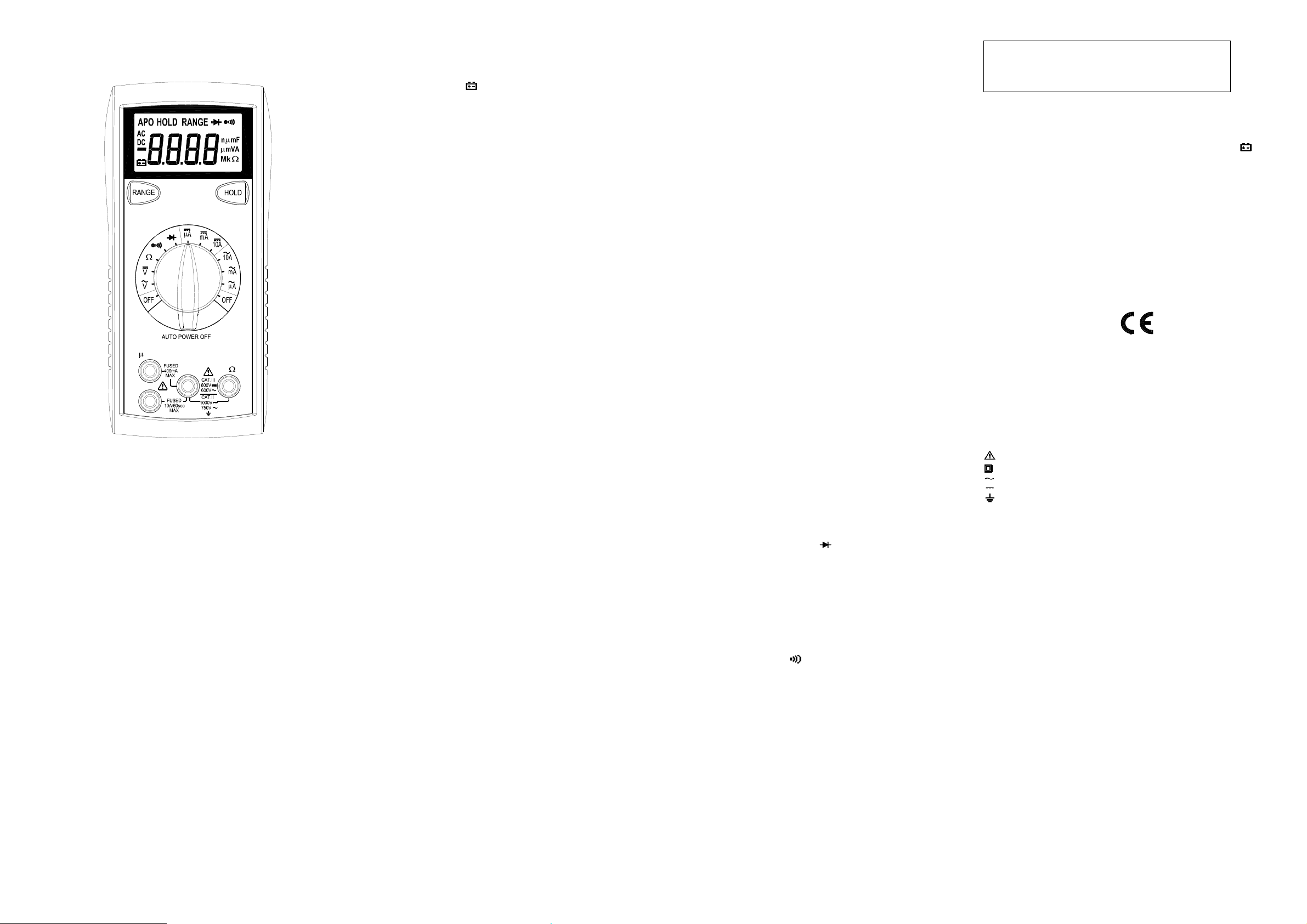
V
SPECIFICATIONS
Display: 3¾ digitliquid crystaldisplay (LCD)with a maximum reading of 3999.
Polarity: Automatic, positiveimplied, negative polarityindication.
Overrange: (OL) or (-OL)is displayed.
Zero: Automatic.
Low battery indication: The
belowthe operatinglevel.
Measurement rate: 2 times persecond, nominal.
Autopower off: Approx. 10minutes.
Operating environment: 0℃ to 50℃ at < 70% relative humidity.
Storage temperature: -20℃ to 60℃, 0 to 80% relative humidity.
Accuracy: Stated accuracyat 23℃±5℃, < 75% relative humidity.
Temperature Coefficient: 0.1 x (specified accuracy) per ℃. (℃ to 18℃, 28℃
to 50℃).
Altitude: 6561.7 feet (2000m).
Power: Singlestandard9-volt battery, NEDA1604,JIS 006P,IEC 6F22.
Batterylife: 200 hours typical withcarbon-zinc.
Dimensions: 165mm(H) x78mm (W) x42.5mm (D).
Weight: Approx. 10.0 oz.(285g) includingholster.
Accessories: One set testleads, onespare fuse, 9V battery (installed), and
Operating Instructions.
is displayed when thebattery voltage drops
" "
DC VOLTS
Ranges: 400mV,4V, 40V,400V,1000V
Resolution: 0.1mV
Accuracy: ± (1 .0 %r dg +2 dg ts )
Inputimpedance: 400mV:>100MΩ; 4V:10MΩ; 40V ~ 1000V:9.1MΩ
Overload protection: 1000VDC or 750VAC rms
AC VOLTS (50Hz- 500Hz)
Ranges: 400mV,4V, 40V,400V,750V
Resolution: 0.1mV
Accuracy:
±( 2.0% rdg+ 5 dgts)50 ~100Hzon 400mVrange
±( 2.0% rdg + 5 dgts)
Inputimpedance: 400mV:>100MΩ; 4V:10MΩ; 40V ~750V:9.1MΩ
Overload protection: 1000VDC or 750VAC rms
CURRENT
Ranges: 400uA, 4000uA, 40mA, 400mA,10A
Resolution: 0.1uA
DC accuracy:
±( 2.0% rdg+ 2 dgts)on 400uAto 400mAranges
±( 3.0% rdg+ 3 dgts)on 10A range
AC accuracy: (50Hz ~ 500Hz)
±( 2.5% rdg+ 5 dgts)on 400uAto 400mAranges
±( 3.5% rdg+ 5 dgts)on 10A range
Voltageburden: 0.2V on 400uA, 40mA, 10Aranges
2V on 4000uA, 400mAranges
Inputprotection: 0.5A/500Vfast blow ceramicfuse
10A/600V fast blowceramic fuse
10AInput: 10A for60 seconds maximumfollowed
by a 10 minutecooling period
RESISTANCE
Ranges: 400Ω, 4kΩ, 40kΩ, 400kΩ, 4MΩ,40MΩ
Resolution: 0.1Ω
Accuracy:
±( 1.5% rdg+ 4 dgts)on 400Ωto 400kΩranges
±( 2.5% rdg+4 dgt) on 4MΩrange
±( 5.0% rdg+ 5 dgt)on40MΩrange
Open circuit volts: -0.45Vdc (-1.2Vdcon 400Ωrange)
Overload protection: 500VDC orAC rms
DIODE TEST
Test current: 1.0mA(approximate)
Accuracy: ±(3.0% rdg + 3 dgts)
Resolution: 10mV
Audible indication: <0.25V
Open circuit volts: 3.0Vdc typical
Overload protection: 500VDC orAC rms
CONTINUITY
Audible indication: Less than 25Ω
Response time: 500ms
Overload protection: 500VDC orAC rms
Input Warning Beeper
The meterhas a beeper thatwarns the userwhen the test leadis in thecurrent
jack while the meter is switched to makea voltage measurement.Anothersafety
feature to protect themeter and you.
Data Hold Feature
Press[HOLD] buttonto lock the reading on display, and release it by pressing
the button again.
Manually Selecting Range
The meteralso has a manualrangemode. In manualrange, youselect and lock
the meterin a range. To manually select a range:
Press[RANGE] buttonto hold the selected range.Subsequently pressingthe
[RANGE] button willselect each range in sequencefrom the lowest tohighest
range. Hold the buttonfor 2 seconds to return to the Autorange Mode.
Voltage Measurements
1.Connect the red testlead to ”VΩ”jack and the blacktest lead to the ”COM”
jack.
2.Setthe Function/Range switchto the desiredvoltagetype (AC or DC) and
range. If magnitudeof voltage is not known, set switch to the highest range
and reduce until a satisfactory readingis obtained.
3.Connect the test leadsto the deviceor circuit beingmeasured.
4. For dc, a (-) sign is displayed for negative polarity;positivepolarity is implied.
CurrentMeasurements
1.Connect the red testlead to the (uA, mAor 10A) jack and theblack test leadto
the "COM" jack.
2.Setthe Function/Range switchto the DC orAC ranges.
3.Remove powerfromthe circuit under test and open thenormal circuitpath
wherethe measurement is to be taken.Connect themeter in series withthe
circuit.
4.Apply power and read the valuefrom the display.
Resistance Measurements
1.Setthe Function/Range switchto the desiredresistancerange.
2.Reove power from the equipment under test.
3.Connect the redtest lead tothe"VΩ" jack andthe blacktest lead to the"COM"
jack.
4.Connectthe test leads to the points of measurements andread the value from
the display.
Diode Tests
1.Connect the red testlead to the “VΩ” jack and the blacktest lead to
the ”COM” jack.
2.Setthe Function/Range switchto the “ “ position.
3.Turn off power to the circuitunder test. External voltageacross the
components causesinvalidreadings.
4.Touch probesto thediode.A forward-voltage drop is about0.6V (typicalfor a
silicondiode).
5.Reverse probes.If the diode is good, “OL”is displayed. If thediode is shorted,
“000” or another number is displayed.
6. If the diodeis open,“OL” is displayed in bothdirections.
7.Audible Indication: Less than 0.25V.
Continuity Measurements
1.Setthe Functionswitch to the position.
2.Turn off powerto the circuit undertest. External Voltage across the
components causesinvalidreading.
3.Connect the test leadsto the two points at which continuity is to be tested.The
buzzer will sound if the resistance is lessthan approximately25Ω.
Auto Power Off
1.Auto power off:approx.10 minutes.
2.After autopower off, pressany buttonto restart the meter, and the reading of
measurement willbe maintainedin the display.
Cancellation of Auto Power Off Feature:
Pressand hold the (RANGE) button whilerotatingfunction switchfrom off to
anyposition to turn the meter on.The auto poweroff featureis disabled.
Note“APO” annunciatoris missing from theLCD.
MAINTENANCE
Removetest leads before changingbatteryor fuse or
performing any servicing.
WARNING
Battery Replacement
Poweris suppliedby a 9 voltbattery. (NEDA1604,IEC 6F22).The
on the LCDdisplay whenreplacement is needed.To replace the battery, remove
the threescrews fromthe back of the meter andlift off thefront case. Remove
the battery from case bottom.
" "
appears
Fuse Replacement
If no current measurements are possible. Check fora blown overload protection
fuse.For access to fuses,remove thethree screwsfrom the back of themeter
and liftoff the frontcase. ReplaceF1 only with the original type 0.5A/500V,fast
actingceramic fuse,6.35x32mm Replace F2 onlywith the original type
10A/600V, fast actingceramicfuse, 6.35x25.4mm.
Cleaning
Wipe thecase with a damp clothand mild detergent. Do not use abrasives or
solvents. Dirt or moisture in the terminals can affectreadings.
Safety: Conformsto IEC61010-1 (EN61010-1), CATII 1000V, CATIII 600V, Class
CATII: Is for measurements performed on circuitsdirectlyconnectedto the
CAT III: Is for measurements performed in the building installation.
EMC: Conformsto EN61326.
The symbols used on this instrument are:
II, Pollution degree2 Indoor use.
low-voltageinstallation.
Caution, refer to accompanyingdocuments
Equipment protected throughout by Doubleinsulation(Class II)
Alternating current
Directcurrent
Ground
OPERATION
Beforetaking anymeasurements, readthe Safety Information Section. Always
examine the instrument for damage,contamination (excessive dirt,grease, etc.)
and defects. Examinethe test leads for cracked orfrayed insulation. If any
abnormal conditions exist do not attempt to make any measurements.
Page 2
INSTRUCCIONES DE FUNCIONAMIENTO
2. Seleccione la Función / Rango a al posición de "(diode symbol)".
6. Si el diodo está abierto, el "OL" se muestraen ambas direcciones.
MODELO 2705B
MULTIMETRO DIGITAL
2705B
A mA
COM
10A
V
INFORMACION DE SEGURIDAD
La siguiente información relativa a la seguridaddeben ser observadas para
garantizar la máximaseguridadpersonaldurante la operación de este metro:
Utiliceelmedidorsólocomo seespecificaeneste manual o laprotección prevista
en el metropodría verseafectada.
Pruebe deque elmedidoren un voltaje conocido antesdeusarlopara determinar
si está presente la tensiónpeligrosos.
Noutiliceel medidorsi elmedidoro losconductores depruebaparecendañados,
o si sospechaque el medidorno está funcionando correctamente.
Nuncaesté conectado a tierra cuando este tomandomedicioneseléctricas. No
toquelas tuberíasde metalexpuesto, puntos de venta, accesorios, etc, que
podránestar conectados a tierra. Mantengasu cuerpo aislados de tierra
mediante el uso de ropa seca,zapatosde goma, alfombras de caucho,o
cualquier materialaislanteaprobado.
Apague la potenciaal circuito bajo pruebaantes de cortar, quitar soldadura, o
romperel circuito.Pequeñascantidadesde corrientepueden serpeligrosas.
Tengacuidado cuando se trabaja con mas de60V de CD o 30 V CArms. Esas
tensiones plantean un peligro dechoque.
Al utilizar las sondas, mantengalos dedos detrásdel dedo de la manode los
guardias de las sondas.
La medición de tensión queexcede los límites del multímetro puede dañar el
medidor y el operadorse puede de exponera un peligro de choque. Siempre
reconozca los límitesde voltajeen el frente del medidor.
ESPECIFICACIONES
Pantalla: 3 ¾ dígitos, pantalla de cristal líquido (LCD) con un máximo de
lectura de 3999.
Polaridad: Automática, positiva implícita, indicación de polaridad negativa.
Overrange: (OC) o (-OC) aparece en pantalla.
Cero: Automático.
Indicación de batería baja:El
aparece cuando el voltajede la batería
" "
cae por debajo del nivel de funcionamiento.
Tipo de Medición: 2 veces por segundo, nominal.
Apagado automático: aprox. 10 minutos.
Entorno operativo: 0℃ a 50℃ a <70% de humedad relativa.
Temperatura de almacenamiento: -20℃a 60℃, de 0 a 80% de humedad
relativa.
Precisión: Dicho de precisión a 23℃± 5℃, <75% de humedad relativa.
Coeficiente de temperatura: 0.1 x (exactitud especificada) por ℃. (℃ a 18
℃, 28℃a 50℃).
Altitud: 6561,7 pies (2000m).
Potencia: El único estándar de la batería de 9 voltios, NEDA 1604, JIS
006P, IEC 6F22.
La duración de la batería: 200 horas típico con carbono-zinc.
Dimensiones: 165mm (H) x78mm (W) x42.5mm (D).
Peso: aprox.10.0 oz (285g) incluyendo funda.
Accesorios: Un conjunto conductores de prueba, un fusible de repuesto,
batería de 9V (instalada), y Manual de instrucciones.
VOLTIOS CD
Rangos: 400mV, 4V, 40V, 400V, 1000V
Resolución: 0.1mV
Precisión:± (1,0% lectura +2dgts)
Impedancia de entrada:400mV:> 100MΩ; 4V:10MΩ;40V ~ 1000V: 9.1MΩ
Protección de sobrecarga: 1000VCD o 750VCA rms
VOLTIOS AC (50Hz - 500Hz)
Rangos: 400mV, 4V, 40V, 400V, 750V
Resolución: 0.1mV
Precisión:
± (2.0% lectura + 5dgts) 50 ~ 100Hz gama de 400mV
± (2.0% lectura + 5dgts)
Impedancia de entrada: 400mV:> 100MΩ; 4V: 10MΩ; 40V ~750V: 9.1MΩ
Protección de sobrecarga: 1000VDC o 750VACrms
Corriente
Rangos: 400uA, 4000uA, 40 mA, 400mA, 10A
Resolución: 0.1uA
DC precisión:
± (2.0% lectura + 2dgts) sobre rangos de 400uA a 400mA
± (3.0% lectura + 3dgts) en la gama 10ª
Precisión CA: (50Hz ~ 500Hz)
± (2.5% lectura + 5dgts) sobre rangos de 400uA a 400mA
± (3.5% lectura + 5dgts) en la gama 10A
Tensión de carga: 0.2V en 400uA, 40mA, 10A rangos
4000uA sobre 2V, 400mA rangos
Entrada de protección: 0.5A/500V fusibles rápido de cerámica
10A/600V fusibles rápido de cerámica
10A Entrada: 10A máximo durante 60 segundos seguidos
Por 10 minutos en un período de enfriamiento
RESISTENCIA
Rangos: 400Ω, 4kΩ, 40kΩ, 400kΩ, 4MΩ, 40MΩ
Resolución: 0.1Ω
Precisión: ± (1.5% lectura + 4dgts) sobre 400Ω a 400kΩrangos
± (2.5% lectura +4dgt) en la gama 4MΩ
± (5.0% lectura + 5dgt) en la gama 40MΩ
Voltios circuito abierto:-0.45Vdc (-1.2Vcd gama de 400Ω)
Protección de sobrecarga: 500VCD o CA rms
PRUEBA DE DIODO
Corriente de Prueba: 1.0mA (aproximadamente)
Precisión: ± (3.0% lectura + 3dgts)
Resolución: 10mV
Audible indicación: <0.25V
Voltios circuito abierto: 3.0Vcd típico
Protección de sobrecarga: 500VCD o CA rms
CONTINUIDAD
Indicación audible: Menos de 25Ω
Tiempo de respuesta: 500ms
Protección de sobrecarga: 500VCD o CA rms
OPERACIÓN
Antes de tomar cualquier medida, lea la sección de Información sobre
Seguridad. Siempre examine el instrumento para para daños, la
contaminación (exceso de suciedad, grasa, etc) y defectos. Examine los
conductores de prueba para agrietados o rotos aislamiento. Si alguna de la
condiciones existe no intente realizar las mediciones.
Entrada zumbador de aviso
El medidor tiene un zumbador que avisa al usuario cuando el conductor de
prueba está en el actual jack mientrasque el medidor se encuentre conectado
a hacer una medición de tensión. Otra característica de seguridad para
proteger el medidor y usted.
Retención de Datos
Oprime el botón [HOLD] para bloquear la lectura en la pantalla, y lo liberan
al presionar el botón de nuevo.
Seleccionando manualmente gama
El metro también tiene un modo manual de gama. En el manual de gama,
que seleccione, así como bloquear el medidor en un rango.
Para seleccionar manualmente un rango:
Oprime el botón [RANGE] para seleccionar el rango. Posteriormente
presionar el botón de [RANGE] seleccionará cada variedad en la secuencia
de menor a mayor rango. Mantiene pulsado el botón durante 2 segundos
para volver a la modalidad de Autorange.
Las mediciones de voltaje
1.Conecte el conductor rojo de prueba a la "V Ω" jack y el conductor negro
de prueba a la "COM" jack.
2. Seleccione la Función / Rango de cambio al tipo deseado de voltaje (CA
o CD) y la variedad. Si la magnitud de la tensión no es conocida,
sistemáticamente cambie a una escala mayor y reduzca el rango a una
manera satisfactoria hasta que se obtenga la lectura adecuada.
3. Conecte los conductores de prueba al dispositivo o circuito con que se
mide.
4. Para muestra polaridad negativa, un (-) se demuestra; polaridad positiva
es implicado.
Las mediciones de Corriente
1.Conecte el conductor rojo de prueba a la (tC, mA o 10A) jack y el
conductor negro de prueba a la "COM" jack.
2. Seleccione la Función / Rango para cambiar de los rangos de CD a CA.
3. Elimine el poder del circuito bajo prueba y abra el circuito normal de ruta
donde la medición es que se deben tomar. Conecte el medidor en serie con
el circuito.
4. Aplicar y poder leer el valor de la exhibición.
Mediciones de Resistencia
. Seleccione la Función / Rango cambiar a la resistencia deseada gama.
2. Elimine el poder de los equipos bajo prueba.
3. Conecte el conductor rojo de prueba a la "V Ω" jack y el conductor negro
de prueba a la "COM" jack.
4. Conecte los conductores de prueba a los puntos de medición y lea el
valor de la exhibición.
5. Toque lassondas a los puntos deprueba. En ohmios, el valor indicadoen
la pantalla es elvalor medido de la resistencia. En la continuidad deprueba,
el zumbador suena continuamente, si la resistencia es inferior a 100Ω.
Prueba de Diodo
1.Conecte el conductor rojo de prueba a la "V Ω" jack y el conductor
negro de prueba a la "COM" jack.
3. Elimine el poder de los equipos bajo prueba. Exteriores voltaje a
través de loscomponentes causas lecturas no válidas.
4. Toque las sondas al diodo. Una caída de tensión hacia
adelante-es de unos 0.6V (típico para un diodo de silicio).
5. Reverse sondas. Si el diodo es bueno, el "OL" se muestra. Si el
diodo está e n cortocircuito, "000" u otro número aparece en la
pantalla.
7. Indicación audible: Menos de 0.25V.
Medidas de continuidad
1. Seleccione la Función / Rango a al posición de "(continuity symbol)".
2. Elimine el poder de los equipos bajo prueba. Exteriores voltaje a través
de los componentescausas lecturas no válidas.
3. Conecte los conductores de prueba a los dos puntos en los que la
continuidad es someterse a la prueba. El zumbador sonará si la resistencia
es menor a aproximadamente 25Ω.
Apagado automático
1. Apagado automático: aprox. 10 minutos.
2. Después de apagadoautomático, oprime cualquier botón parareiniciar el
medidor, y la lectura de la medición se mantendrá en la pantalla.
Cancelación de la función de apagado automático:
Oprime y mantenga oprimido el botón (GAMA), mientras que la rotación de
la función fuera a cambiar de cualquier posición a su vez, en el medidor.La
función de apagado automático está desactivada.
Nota "APO" anunciador falta en la pantalla LCD.
MANTENIMIENTO
ADVERTENCIA
Eliminar conductores de prueba antes de cambiar la batería o
fusible o realización de cualquier servicio.
Reemplazo de baterías
La potencia es suministrada por una batería de 9 voltios. (NEDA 1604, IEC
6F22). El
aparece en pantalla, cuando el reemplazo es necesario.
" "
Para sustituir la batería, quitar los tres tornillos de la parte posterior del
medidor y el ascensor frente a la parte delantera caso. Extraiga la batería
caso de la parte inferior.
Reemplazo de fusibles
Si lasmedicionesactuales nosonposibles. Horas desoplado de fusibles de
protección de sobrecarga. Para el acceso a los fusibles, quitar los tres
tornillos de la parte posterior del medidor y el ascensor frente a la parte
delantera caso. Sustituir F1 sólo con el tipo original 0.5A/500V, actuando
rápida de fusibles de cerámica, 6.35x32mm.
Sustituir F2sólo con el original 10A/600Vtipo, que actúan rápido defusibles
de cerámica, 6.35x25.4mm.
Limpieza
Limpie el casocon un paño húmedo y detergente suave. No utilice
productos abrasivos o disolventes. La humedad o la suciedad en los
terminales pueden afectar a las lecturas.
Seguridad: Cumple con IEC61010-1 (EN61010-1), CATII 1000V, CATIII
600 V, clase II, grado de contaminación 2 Salas de uso.
CATII: Es para las mediciones realizadas en los circuitos conectados
directamente a la instalación de baja tensión.
CAT III: Es para las mediciones realizadas en la construcción de la
instalación.
EMC: Cumple con EN61326.
Los símbolos utilizados en este instrumento son:
Precaución, refiérase a los documentos que la acompañan
Equipo protegido en todo momento por doble aislamiento (clase II
Corriente alterna
Corriente
Ground
Page 3

Manuel d’utilisation
Modèle 2705B
Multimètre Numérique 4000 points
2705B
A mA
COM
10A
PRESCRIPTIONS DE SECURITE
Les prescriptionsde sécurité ci dessous sont à suivrescrupuleusement afinde
garantir la sécuritéde l’utilisateur:
N’utiliser votre appareil que dansle domaine d’utilisation défini dansce manuel.
Dansle cas contraireles protections pourraient être endommagées.
Toujours tester votreappareilsur une tensionconnue avantde l’utiliserpour une
mesurede tension.
Ne pasutiliser votreappareilo uses cordons voussemblent endommagés.
Ne jamaisvous mettreà la terrelorsquevous faites desmesures de tension. Ne
jamaistoucher despartiesmétalliques qui pourraient être reliéesà la terre lors
d’unemesure. Dansla mesure du possible,isolez-vous de la terrepar des
chaussures, vêtements ou gantsappropriés.
Pensezà couper le courant avant d’ouvrir un circuit ou d’intervenirsur celui-ci.
Mêmeun faible potentiel peut êtredangereux.
Prenez toutes les précautions nécessaireslorsque vousintervenez sur des
tensions supérieures à 60V DC ou 30VAC eff.
Lorsque vous utilisezdes pointesde touche, ne jamaismettre les doigts au delà
des anneaux de garde.
Mesurer des tensionsou grandeursau delà des limitesde l’appareil peut
endommager les protections, endommager votreappareil et mettre en danger la
sécurité de l’utilisateur.Assurez vous de connaître les limitesde votre appareil,
avantutilisation.
V
SPECIFICATIONS
Affichage: 3 3/4 digits (LCD) avecun affichage de 3999 maximum
Polarité:Automatique,avec indication du signemoins.
Dépassement: (OL)ou (-OL) est affiché.
Zéro:Automatique.
Indication de pile usée:le symbole
qu’ilfaut la remplacée.
Cadence de mesure: 2 fois/s(typique)
Arrêtautomatique: après environ 10 minutes.
Température de fonctionnement:0℃ à 50℃ avec HR < 70%.
Température de stockage: -20℃ à 60℃,HR de 0 à 80%.
Précision: donnéeà 23℃ ±5℃, HR < 75%.
Coefficient de température:0.1 x (précision)par ℃. (℃ < 18℃, et de 28℃ à
50℃).
Altitude: utilisation jusqu’à2000m.
Alimentation:pile 9 V type NEDA1604, JIS 006P, IEC 6F22.
Autonomie: 200 heures typique.
Dimensions: 165mm(H) x 78mm (W) x 42.5mm(D).
Masse:environ285g avec gaine
Accessoires: jeu decordons, fusible de rechange, pile (9V) installée, manuel.
est affiché lorsquela pile est usée et
" "
TENSIONS DC
Gammes: 400mV,4V, 40V, 400V,1000V
Résolution: 0.1mV
Précision: ± (1 .0 %r dg +2 dg ts )
Impédance d’entrée: 400mV: >100MΩ; 4V:10MΩ; 40V ~1000V:9.1MΩ
Protection: 1000VDCou 750VAC eff.
TENSIONSAC(50Hz- 500Hz)
Gammes: 400mV,4V, 40V, 400V,750V
Résolution: 0.1mV
Précision:
±( 2.0% + 5 dgts)50 ~100Hz surgamme400mV
±( 2.0% + 5 dgts)
Impédance d’entrée: 400mV: >100MΩ;4V:10MΩ; 40V ~ 750V:9.1MΩ
Protection: 1000VDCou 750VAC eff.
COURANTS DC et AC
Gammes: 400uA, 4000uA, 40mA, 400mA,10A
Résolution: 0.1uA
Précision en DC:
±( 2.0% + 2 dgts)de 400uAà 400mA
±( 3.0% + 3 dgts)sur 10A
Précision en AC: (50Hz ~ 500Hz)
±( 2.5% + 5 dgts)de 400uAà 400mA
±( 3.5% + 5 dgts)sur 10A
Voltageburden: 0.2V sur 400uA, 40mA, 10A
2V sur 4000uA, 400mA
Protection: Fusible F0.5A/500V(céramique rapide)
Fusible F10A/600V(céramiquerapide)
Entrée10A: 10A pendant 60 secondesmaximum suivid’une période sans
courant de 10minutesminimum
RESISTANCE
Gammes: 400Ω, 4kΩ, 40kΩ,400kΩ,4MΩ, 40MΩ
Résolution: 0.1Ω
Précision:
±( 1.5% + 4 dgts)de 400Ωà 400kΩ
±( 2.5% +4 dgt)sur 4MΩ
±( 5.0% + 5 dgt) sur 40MΩ
Tension en circuit ouvert: -0.45Vdc (-1.2Vdc sur 400Ω)
Protection: 500VDC ou AC eff.
TEST DIODE
Courant de test: 1.0mA(typique)
Précision: ±(3.0% + 3 dgts)
Résolution: 10mV
Indication sonore: <0.25V
Tension en circuit ouvert: 3.0Vdctypique
Protection: 500VDC ou AC eff.
Alerte sonore pour cordons mal positionnés
Le multimètre disposed’une alarmesonore si vousavez un cordonbranché
dansla bornemA ouA etsi le commutateur estsur une mesurede tension. Dans
ce cas vérifiez impérativement le branchement.
Fonction HOLD
Appuyer sur la touche[HOLD] pour figerl’affichage (HOLD).Un nouvel appui
permetun retour à un affichage normal.
Utilisation en gammes manuelles
Le multimètre peut êtreutilisé en gammes manuelles,ce qui peut êtretrès
pratiquepour certaines applications. Pour cela:
Appuyer sur la touche[RANGE] afin de figerla gamme. D’autres appui sur
[RANGE] feront défiler les gammes dansle sens croissant. Pour repasser en
mode automatique,appuyersur [RANGE] pendant plus de 2s.
Mesures de tension
1. Brancher le cordonrouge à la borne ”VΩ” et le cordon noir à la borne”COM”.
2. Positionner le commutateur surla fonction appropriée DCou AC.
3. Brancher les cordonssur votre application.
4. Lirele résultat surl’afficheur LCD. La polarité est indiquée avec le signe(-)en
DC
Mesures de courant
1. Brancher le cordonrouge à la borne µA/mAou 10A, et le cordon noir à la
borne”COM”.
2. Positionner le commutateur surla gamme appropriée en DC ouAC.
3.Assurez-vous que le circuità mesurer est hors tension et branchezvos
cordons en série dansce circuit.
4. Mettresous tensionet lire le courantsur l’afficheur LCD
Mesures de résistance
1. Positionner le commutateur rotatif sur la fonction Ω
2.Assurez-vous que le dispositif à mesurer soithorstension.
3. Brancher le cordonrouge à la borne ”VΩ” et le cordon noir à la borne”COM”.
4. Branchez les cordonsà votre application ou testerpar contactavec les
pointes de touche.
Test Diode
1.Brancherle cordonrouge à la borne ”VΩ” et le cordon noirà la borne ”COM”.
2. Positionner le commutateur sur“ “.
3.Assurez-vous que le dispositif à mesurer soithorstension,afin de ne pas
fausserla mesure.
4. Testerla diode à l’aidedes pointes detouché:le sens passantd’une diode
silicium fait apparaitre une tension de 0.6V (typique)
5. Une diode ouverteousens bloqué se traduira par un affichage “OL”. Une
diodeen court-circuitse traduirapar un affichage “000” ou prochede 0.
6. Remarque: une diode ouverte donne un affichage “OL”dans les 2 sens
7. Signalsonore pourune tension< 0.25V
Test de continuité
1. Positionner le commutateur sur
2.Assurez-vous que le dispositif à mesurer soithorstension,afin de ne pas
fausserla mesure.
3. Branchez les cordonsà votre applicationou tester parcontact avecles
pointes de touche. Le buzzer est actif pourR<25 ohms.
Arrêt automatique
1.Après environ 10 minutes.
2.Après un arrêtautomatique, un appui sur unetouché ou une remiseen
marcheparle commutateur permet uneremise en fonctionnement normal.
Inhibition de l’arrêt automatique:
Appuyer sur la touche(RANGE) à la mise en marchede l’appareil. L’arrêt
automatique est alorsinhibé.
Remarque: le symbole “APO” n’apparait plus à l’affichage.
MAINTENANCE
" "apparaità l’affichage il faut remplacer la pile.Assurez-vous d’avoir
débranché les cordons. Dévisserle fond de boitieret remplacerla pile. Revisser
le fondde boitier.
Remplacement des fusibles
Si les mesures de courantne fonctionnent pas, il faut vérifierl’état desfusibles
qui assurent la protection de votre multimètre.
les cordons. Dévisserle fond de boitieret vérifierles fusibles :
F1 0.5A/500V, type céramique F (rapide), 6.35x32mm.
F2 10A/600V, type céramique F (rapide),6.35x25.4mm.
Attention : Ne remplacerles fusiblesqu’avec le mêmetype.
Assurez-vous d’avoirdébranché
Nettoyage
Nettoyer périodiquement avecun chiffondoux et humide. Nepas utiliserde
solvants. Saletéet/ou humiditéau niveaudes douilles peuvent perturber les
mesures et donner desindicationsfausses.
Sécurité: IEC61010-1 (EN61010-1),CATII1000V, CATIII 600V, ClassII, Degré
de pollution 2, utilisation à l’intérieur.
CATII / CAT III : se reporteraux normes pour la définition des catégories
d’installation
EMI: selon EN61326.
Symboles utiliséssur l’appareil:
Attention– Danger: se référerau manuel
Double isolement(Classe II)
Courant alternatif
Courant continu
Terre
CONTINUITE
Indication sonore(buzzer): pourR< 25Ω
Temps de réponse: 500ms
Protection: 500VDC ou AC eff.
MISE EN OEUVRE
Avant toute mesure,assurez-vousd’avoir pris connaissancedes Prescriptions
de Sécurité. Toujoursvérifierque l’appareil et ses cordonsne sont pas
endommagés. Si vousavez le moindredoute, ne pas effectuer de mesure.
ATTENTION- DANGER
maintenance – Risquede choc électrique.
Remplacement de la pile
Votre multimètre utiliseune pile9V.(NEDA1604,IEC 6F22). Lorsque le symbole
Page 4

BEDIENUNGSANLEITUNG
DIGITAL-MULTIMETER
MODELL 2705B
2705B
A mA
COM
10A
SICHERHEITSINFORMATIONEN
Um ein Maximum an persönlicher Sicherheit beim Betrieb dieses Multimeters zu
gewährleisten,bitte unbedingt folgendeSicherheitshinweise beachten:
Das Gerät nur nach der in dieserBedienungsanleitung angegebenen Spezifikationverwenden. Ansonsten könnendie im Messinstrument vorhandenen
Schutzmechanismen außer Kraft gesetzt sein.
TestenSie das Multimeterzuerstmit einer bekannten Spannung, bevorSie es
dafürverwenden, das Vorhandenseinvon gefährlichen Spannungen zu überprüfen.
Das Multimeter nichtverwenden, wenn das Instrument oder diePrüfkabel Beschädigungenaufweisen oderwenn Sie den Eindruck haben,dass das Gerät
nichtordnungsgemäß funktioniert.
Bei Durchführungelektrischer Messungenkeine Erdung zum eigenenKörper
herstellen. Niemals offen liegende, blankeKabel,Ausgänge,Anschlüsse, Vor-
richtungen, Halterungenberühren, um jeglichen Kontaktmit Erdpotential zu vermeiden. Sorgen Sie dafür, dassIhr Körpervon der Erde isoliertbleibt, indemSie
trockene Kleidung, Gummischuhe, Gummimatten oder anderes zugelassenes
Isolierungsmaterial verwenden.
Schalten Sie denzu prüfendenSchaltkreiszuerststromlos,bevorSie ihntrennen,
ablöten oder unterbrechen.Auch geringe Strommengen könnengefährlichsein.
SeienSiebesondersvorsichtig, wennSiemitSpannungenarbeiten, die über60V
Gleichstrom oder30 V Wechselstrom Effektivwert (rms)liegen. Spannungenin
dieserHöhe lösenelektrischeSchlägeaus.
Beim Umgang mit den Prüfspitzen dieFinger bitte stetshinter derAbschirmung
des Isoliergriffshalten.
DieMessungvonSpannungen,die die Grenzwerte des Multimeters übersteigen,
kanndas Gerät beschädigen undden Bedienerder Gefahr eines Stromschlags
aussetzen. Beachten Sie bitte stetsdie auf der Vorderseite des Geräts
angegebenen Spannungsgrenzwerte.
V
TECHNISCHE DATEN
Display: 3½ -stelligeFlüssigkristallanzeige (LCD) mit max.1999 Zählimpulsen.
Polarität: Automatisch, positivePolaritätimplizit, negative wirdangezeigt.
Bereichsüberschreitung: Anzeigevon (OL) oder(-OL).
Null:Automatisch
Indikator bei schwacher Batteriespannung: Sinkt die Batteriespannung unter
das Betriebsniveau, wird das Symbol
Messrate: Nennwert2,5Mal proSekunde.
AutomatischeAbschaltung: nachca. 30 Minuten Inaktivität
Betriebsumgebung: 0℃ bis 50℃ bei einerrelativen Feuchtigkeit < 70%.
Lagertemperatur: -20℃ bis 60℃, 0 bis 80% relativeFeuchtigkeit.
Genauigkeit:Angabengeltenfür 23℃ ±5℃ und einerrelativenFeuchte< 75%.
Temperaturkoeffizient:0,1 x (spezifizierte Genauigkeit) pro ℃. (℃ bis 18℃, 28
℃ bis 50℃).
Maximale Höhenlagefür den Betrieb: 2000m.
Stromversorgung: 9-Volt-Bockbatterie, TypNEDA1604, JIS 006P, IEC 6F22.
Batterielebensdauer: 150 Stunden typischfür Kohle-Zink.
Abmessungen: 165 mm (H) x 78 mm (B) x 42,5mm (T).
Gewicht: ca. 285 g inkl. Holster.
Zubehör: 1 Satz Prüfkabel, 1 Stk. Ersatzsicherung, 9 V-Batterie(eingelegt) und
Bedienungsanleitung.
GLEICHSPANNUNG
Bereiche: 400mV,4V,40V, 400V,1000V
Auflösung: 0,1mV
Genauigkeit: ± (1% des Messwerts + 2 Stellen)
Eingangsimpedanz:400mV:>100MΩ; 4V:10MΩ; 40V ~ 1000V:9.1MΩ
Überlastschutz: 1000 VDCoder 750 VACEffektivwert
WECHSELSPANNUNG (50 Hz - 500 Hz)
Bereiche: 400mV,4V, 40V, 400V, 750V
Auflösung: 0,1 mV
Genauigkeit:
±( 2%des Messwerts+ 5 Stellen)50 ~100Hz im Bereich400mV
±( 2,%des Messwerts + 5 Stellen)
Eingangsimpedanz: 400mV: >100MΩ; 4V:10MΩ; 40V ~750V:9.1MΩ
Überlastschutz: 1000 VDCoder 750 VACEffektivwert
STROM
Bereiche: 400uA, 4000uA, 40mA, 400mA,10A
Auflösung: 0,1 µA
Genauigkeit Gleichstrom:
±( 2,0% des Messwerts + 2 Stellen) in den Bereichen 400µAbis 400mA
±( 3,0% des Messwerts + 3 Stellen)im 10A-Bereich
Genauigkeit Wechselstrom: (50Hz ~ 500Hz)
±( 2,5% des Messwerts + 5 Stellen) in denBereichen400µAbis400mA
±( 3,5% des Messwerts + 5 Stellen)im 10A-Bereich
Spannungsbürde: 0,2V in denBereichen400µA, 40mA,10A
2V in den Bereichen 4000µA, 40mA
Eingangsschutz: FlinkeKeramiksicherung0,5A / 500 V
FlinkeKeramiksicherung10 A/ 600 V
10 A-Eingang: 10A für 60 Sekunden Maximumgefolgt voneiner
Abkühlphase von10 Minuten
WIDERSTAND
Bereiche: 400Ω, 4kΩ, 40kΩ, 400kΩ, 4MΩ, 40MΩ
Auflösung: 0,1 Ω
Genauigkeit:
±( 1,5% des Messwerts + 4 Stellen) in denBereichenvon 400Ωbis 400kΩ
±( 2,5% des Messwerts + 4 Stellen) im 4MΩ-Bereich
±( 5,0% des Messwerts + 5 Stellen)im 40MΩ-Bereich
Leerlaufspannung: 0,3VDC ( 3 DC im Bereich400Ω)
Überlastschutz: 500 VDC oderAC Effektivwert
DIODENTESTS
Prüfstrom: 1,0mA(ungefähr)
Genauigkeit: ± (3% des Messwerts + 3 Stellen)
Signalton bei: <0,25 V
Leerlaufspannung: 3,0VDC typisch
Überlastschutz: 500 VDC oderAC Effektivwert
DURCHGANGSPRÜFUNG
Signalton bei: unter 25Ω.
Reaktionszeit: 500ms
Überlastschutz: 500 VDC oderAC Effektivwert
angezeigt.
FUNKTIONSBESCHREIBUNG / BETRIEB
BevorSie Messungen durchführen, lesen Sie bitteden Abschnitt Sicherheitsinformationen.Überprüfen Sie das Instrument stets aufBeschädigungen,
Schmutz(übermäßigeVerschmutzungen, Fett usw.) und Defekte. Überprüfen
Sie dieIsolierung der Messleitungen auf Risse oderAbnutzungserscheinungen.
Das Messgerät auf keinenFall verwenden, wenn irgendwelcheungewöhnliche
Bedingungen vorliegen.
Akustisches Warnsignal bei falscher Buchsenbelegung
DasMessgerätverfügtüber einenSummer,der denBenutzerwarnt, wennsich
die Messleitungin derStrombuchse befindetund das Gerät zurSpannungsmessungeingestellt ist. Das ist ein zusätzlichesSicherheitsmerkmalfür Ihre
Sicherheit und zum Schutz des Geräts.
Data Hold
DieTaste[HOLD] drücken um den Messwert auf dem Display“einzufrieren“,die
erneutes drückenwirddie Messung fortgesetzt.
Manuelle Bereichswahl – Taste[Range]
Das Gerät verfügt auchüber einen Modus zur manuellenBereichswahl. Bei der
manuellen Bereichswahl wählen Sie den Bereichund legen diesenfür die
Messungen des Geräts fest. So wählenSie einen Bereichmanuell:
DieTaste[RANGE]drücken, umdenausgewählten Bereichfestzulegen. Durch
nachfolgendesDrücken derTaste [RANGE] wird nacheinander jeder Bereich
vom kleinsten zum größten Bereichausgewählt. Halten Sie dieTaste [RANGE]
für 2 Sekunden gedrückt, um in den Modus der automatischen Bereichswahl
zurückzukehren.
Spannungsmessungen
1.Die roteMessleitung an die Buchse„VΩ” und dieschwarzeMessleitung an die
Buchse„COM“ anschließen.
2.Den Funktions-/Bereichswahlschalter auf den gewünschten Spannungstyp
(AC oderDC) und den Bereicheinstellen. Ist die Größeder Spannung nicht
bekannt, denSchalterauf dengrößtenBereicheinstellen unddannreduzieren,
bis ein zufriedenstellenderMesswert erreicht ist.
3.Die Messleitungenan daszu messende Gerätoder denzu messenden Schaltkreisanschließen.
4.Für Gleichspannung (DC) wirdfür negative Polarität das Zeichen (-)angezeigt;
positive Polaritätist implizit.
Strommessungen
1.Die rote Messleitungan die Buchse „uA,mAoder 10A”und die schwarze
Messleitung an dieBuchse „COM“anschließen.
2.Den Funktions-/Bereichswahlschalter auf den BereichAC oderDC einstellen.
3. Stromversorgung des zu messenden Schaltkreises abschalten und die
normale Leiterbahn öffnen,an der die Messungvorgenommenwerden soll.
Das Multimeter mit demSchaltkreisin Reihe schalten.
4. Den Strom einschalten und den Wertauf dem Displayablesen.
Widerstandsmessungen
1. Den Funktions-/Bereichswahlschalter auf den gewünschten
Widerstandsbereich einstellen.
2.Die Stromquelle deszu messendenGeräts abschalten.
3.Die rote Messleitung an die Buchse „VΩ“ und die schwarze Messleitung an
die Buchse „COM“ anschließen.
4.Die Messleitungenan die Messpunkteanschließenund denWertvom Display
ablesen.
Diodentests
1.Die rote Messleitung an die Buchse „VΩ“ und die schwarze Messleitung an
die Buchse „COM“ anschließen.
2.DenFunktions-/Bereichswahlschalter auf die Position einstellen.
3.Die Stromquelle deszu messendenSchaltkreises abschalten. Externe
Spannungenum die Komponenten herum führen zu fehlerhaften Messwerten.
4.Die Diodemit den Prüfspitzen berühren. DerVorwärts-Spannungsabfall liegt
bei ca. 0,6V (typisch für eine Silikon-Diode).
5.Prüfspitzen vertauschen.Wenndie Diodein Ordnung ist, wird „OL“ angezeigt.Ist die Diode kurzgeschlossen, wird „000“oder eine andere Zahl
angezeigt.
6.Ist die Diodeoffen, wird„OL“ in beidenRichtungenangezeigt.
7. Signalton bei: unter0,25 V.
Durchgangsprüfungen
1. Den Funktions-/Bereichswahlschalter auf die Position “ “ einstellen.
2.Die Stromversorgung des zu messenden Schaltkreises abschalten. Externe
Spannungenum die Komponenten herum führen zu einem fehlerhaften
Messergebnis.
3.Die Messleitungenan die beiden Messpunkte anschließen, an denender
Durchgang zu prüfenist. Der Summerertönt, wennder Widerstandunter
einemWert von ca. 25 Ωliegt.
Automatische Abschaltung
1. Automatische Abschaltung: nachca. 30 MinutenInaktivität
2. Zum Startdes Multimeters nach einerautomatischenAbschaltung eine
beliebige Taste drücken und der Messwert bleibtauf dem Display
erhalten.
Automatische Abschaltung deaktivieren:
DieTaste[Range]gedrückt halten und den Funktions-/Bereichswahlschalter von
OFF zu einer beliebigen Position drehen, um das Multimeter einzuschalten. Die
Funktion der automatischenAbschaltung ist jetzt deaktiviert.
Hinweis:Der Indikator „APO“ (Auto PowerOff) wirdnicht mehr auf dem Display
angezeigt.
WARTUNG
WARNHINWEIS
Vor dem Austausch der Batterie oder der Sicherungen oder anderen
Wartungsarbeiten bitteunbedingtdie Messleitungen abstecken!
Austausch der Batterie
DasGerät wirdvon einer 9 Volt gespeist(NEDA1604, IEC6F22).Wenn ein
Austausch erforderlich ist, erscheint auf demDisplay das Symbol . Zum
Batteriewechselentfernen Sieauf derRückseitedesGerätsdie dreiSchrauben undnehmen das vordere Gehäuseteil ab. Entnehmen Sie danndie
Batterie aus dem Unterteil des Geräts.
Austausch von Sicherungen
Wennkeine Strommessungen möglichsind,überprüfen Sie, ob die Sicherungenfür denÜberlastschutz defektsind. ZumAustausch derSicherungen
diedrei Schrauben aufder Rückseitedes Gerätsentfernen und dasvordere
Gehäuseteil abnehmen. Die Sicherung F1 nur mit eineroriginalen, flinken
Keramik-Sicherung desTyps0,5 A/500V, 6,35x 32 mm und die Sicherung
F2 nur miteiner originalen, flinken Keramik-Sicherung desTyps10 A/600V,
6,35 x 25,4mm ersetzen.
Reinigung
Gehäuse mit einem feuchten Tuchund mildem Reiniger abwischen. Keine
Scheuer- oder Lösungsmittel verwenden. Schmutzoder Feuchtigkeit an den
Klemmenkann zu fehlerhaftenMessergebnissen führen.
Sicherheit: Erfülltdie Normen IEC61010-1 (EN61010-1), CATII 1000V, CATIII
600V, KlasseII, Verschmutzungsgrad 2 zurVerwendung in
Innenräumen.
CATII: Gilt für Messungen an Schaltkreisen,die direkt mit eine
Niederspannungseinrichtung verbunden sind.
CATIII: Gilt fürMessungenan Geräten in Festinstallationen in Gebäuden.
EMV: Erfüllt die Norm EN61326.
Folgende Symbolefinden Sie auf dem Gerät:
Vorsicht! BitteSicherheitshinweise in beiliegenden Dokumenten beachten.
Gerätdurchgängig geschütztdurchdoppelteIsolierung(Klasse II)
Wechselstrom
Gleichstrom
Erde
Page 5

Limited Three-Year Warranty
B&K Precision warrants to the original purchaser that its products and the component parts
thereof, will be free from defects in workmanship and materials for a period of th r ee year s
date of purchase from an authorized B&K Precision distributor.
B&K Precision will, without charge, repair or replace, at its option, defective product or component
parts. Returned product must be accompanied by proof of the purchase date in the form of a
sales receipt.
To obtain warranty coverage in the U.S.A., this product must be registered by completing the
warranty registration form on www.bkprecision.com within fifteen (15) days of purchase.
Exclusions: This warranty does not apply in the event of misuse or abuse of the product
or as a result of unauthorized alterations or repairs. The warranty is void if the serial
number is altered, defaced or rem o ved .
B&K Precision shall not be liable for any consequential damages, including without limitation
damages resulting from loss of use. Some states do not allow limitations of incidental or
consequential damages. So the above limitation or exclusion may not apply to you.
This warranty gives you specific rights and you may have other rights, which vary from state-tostate.
from
SERVICE INFORMATION
Warranty Service: Please go to our website,
button to obtain an RMA #. Return the product in the original packaging with proof of purchase to
the address below. Clearly state in writing the performance problem and return any leads, probes,
connectors and accessories that you are using with the device.
Non-Warranty Serv ice : Please go to our website,
service/repair button to obtain an RMA #. Return the product in the original packaging to the
address below. Clearly state in writing the performance problem and return any leads, probes,
connectors and accessories that you are using with the device. Customers not on open account
must include payment in the form of a money order or credit card. For the most current repair
charges please visit
Return all merchandise to B&K Precision Corp. with pre-paid shipping. The flat-rate repair charge
for Non-Warranty Service does not include return shipping. Return shipping to locations in North
American is included for Warranty Service. For overnight shipments and non-North American
shipping fees please contact B&K Precision Corp.
Include with the returned instrum ent your complete return shipping address, contact
name, phone number and description of problem.
www.bkprecision.com and click on “service/repair”.
B&K Precision Corp.
22820 Savi Ranch Parkway
Yorba Linda, CA 92887
www.bkprecision.com
www.bkpreicsion.com & click on the service/repair
www.bkpreicsion.com & click on the
714-921-9095
 Loading...