

Page 1
Data Sheet
Manual Ranging Tool Kit®DMM with Transistor Test
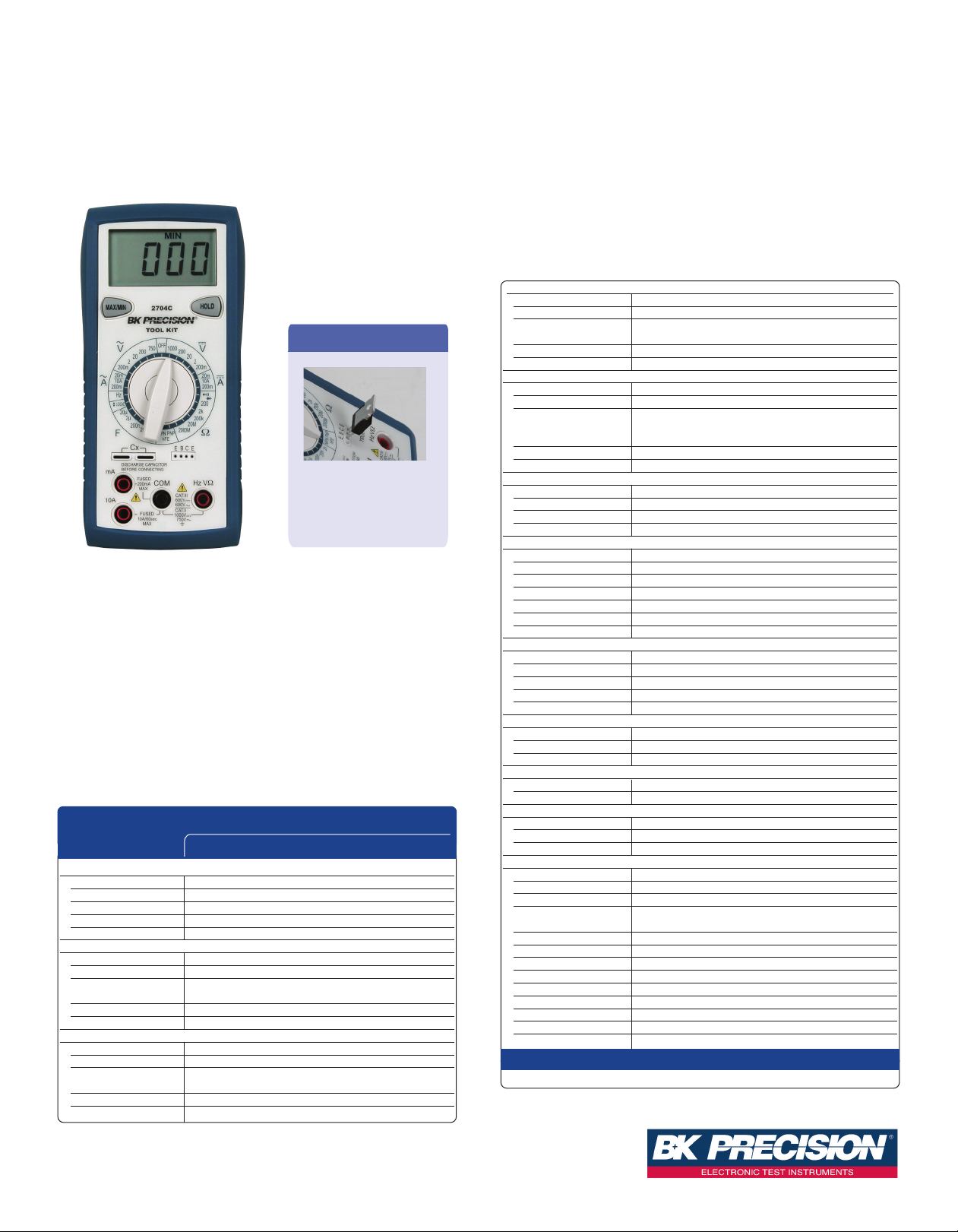
Model 2704C
AC Cur r ent (50 Hz- 500 H z)
Ranges 20 mA, 200 mA, 10 A
esolution 10 uA, 100 uA, 10 mA
R
ccuracy 20 mA to 200 mA ranges: ±(2.0 % rdg + 5 dgts)
hFE Transist or Test
Measures common-
emitter gain.
The 2704C has all of the functionality for basic DMM applications including
some high end features you might not expect. The 2000 count LCD can display
resistance values up to 2 GΩ, capacitance to 20 uF or a transistors
common-emitter gain value up to 1000. Value-packed features make this meter a
must in every "Tool Kit
®
".
Features
■ Magnetic hanger ■ DC voltage to 1000 V
■ AC voltage to 750 V ■ Resistance to 2000 MΩ
■ Capacitance to 20 uF ■ Continuity test
■ Diode test ■ Logic test
■ hFE Transistor test
■ One-handed operation
■ Measures up to 10 A (AC & DC)
Specifications
model
2704C
DC Vol ts
Ranges 200 mV, 2 V, 20 V, 200 V, 1000V
Resolution 0.1 mV, 1 mV, 10 mV, 100 mV, 1 V
Accuracy ±(0.8 % rdg + 1 dgts)
Input Impedance 10 MΩ
Overload Protection 1000 VDC or 750 VACrms*
AC Volt s (5 0 Hz- 5 00 Hz )
Ranges 200 mV, 2 V, 20 V, 200 V, 750V
Resolution 0.1 mV, 1 mV, 10 mV, 100 mV, 1 V
Accuracy 200 mV & 20 V ranges: ±(1.5 % rdg + 5 dgts)
Input Impedance 10 MΩ
Overload Protection 1000 VDC or 750 VACrms*
DC Curr e nt
Ranges 20 mA, 200 mA, 10 A
Resolution 10 uA, 100 uA, 10 mA
Accuracy 20 mA to 200 mA ranges: ±(1.0 % rdg + 1 dgts)
Input Protection 0.5 A/500 V & 10 A/600 V fast blow ceramic fuses
10A Input 10 A for 60 sec max. followed by a 10 minute cooling period
200 V & 750 V ranges: ±(2.0 % rdg + 5 dgts)
10 A range: ±(3.0 % rdg + 3 dgts)
A
Input Protection 0.5 A/500 V & 10 A/600 V fast blow ceramic fuses
0A Input 10 A for 60 sec max. followed by a 10 minute cooling period
1
Re sis tan ce
Ranges 200 Ω, 2 kΩ, 200 kΩ, 20 MΩ, 2000 MΩ
Resolution 0.1 Ω, 1.0 Ω, 100 Ω, 10 kΩ, 1 MΩ
ccuracy 200 Ω to 200 kΩ ranges: ±(1.0 % rdg + 4 dgts)
A
pen Circuit Voltage (typical) 0.3 VDC (3.0 VDC on 200 Ω, 2000 MΩ range)
O
Overload Protection 500 VDC/ACrms
Ca p ac ita nce
Ranges 2 nF , 20 nF, 200 nF, 2.0 uF, 20 uF
esolution 1 pF, 10 pF, 100 pF, 1 nF, 10 nF
R
ccuracy ±(4 % rdg + 10 dgts)
A
Overload Protection Discharge capacitor before connecting
Fr e que n cy
Ranges 2 kHz, 20 kHz, 200 kHz, 2 MHz, 20 MHz
Resolution 1 Hz, 10 Hz, 100 Hz, 1 kHz, 10 kHz
Accuracy ±(0.1 % rdg + 3 dgts)
Sensitivity 2.0 Vrms minimum
Minimum Pulse Width >25 ns
Duty Cycle Limits >30 % and <70 %
Overload Protection 500 VDC/AC rms
Di ode Test
Test Current 1.0 mA (typical)
Resolution 10 mV
Accuracy ±(1.5 % rdg + 3 dgts)
Open Circuit Voltage 3.0 VDC (typical)
Overload Protection 500 VDC/ACrms
Co n tin uit y
Audible Indication Less than 100 Ω
Response Time 100 ms
Overload Protection 500 VDC/ACrms
Tr a nsi s t or hFE
Range 0 to 1000
Base Current Approximately 10 uADC (VCE = 3.0 VDC)
Lo gic Test
Threshold Logic Hi (2.8 V ±0.8 V) / Logic Lo (0.8 V ±0.5 V)
Indication 40 msec beep at logic Lo
Overload Protection 500 VDC/AC rms
Ge ner al
Display 3 1/2 digit, 2000 count LCD
Polarity Automatic, positive implied, negative polarity indication
Overrange OL or -OL is displayed
Low Battery Indication Battery symbol will display when battery voltage drops below
Measurement Rate 2.5 times per second
Operating Environment 0ºC to 50ºC at <70 % relative humidity
Storage Environment -20ºC to 60ºC at 0 to 80 % relative humidity
Accuracies Stated accuracy at 23ºC +5ºC at <75 % relative humidity
Temperature Coefficient 0.1 x (specified accuracy) per ºC. (ºC to 18ºC, 28ºC to 50ºC)
Power Single standard 9 volt battery, NEDA 1604, JIS 006P, IEC 6F22
Battery Life 150 hours typical
Dimensions 165 mm (H) x 78 mm (W) x 42.5 mm (D)
Weight Approximately 10 oz. (285 g) with batter y and hanger
Supplied Accessories: User manual, one set of test leads, one spare fuse, and 9V battery (installed)
*= 600 VDC/Acrms for 15 seconds on 200 mV range
10 A range: ±(3.0 % rdg + 5 dgts)
20 MΩ range: ±(2.0 % rdg + 4 dgts)
2000 MΩ range: ±(5.0 % rdg + 10 dgts)
operating levels
Three-Year Warranty
Technical data subject to change
© B&K Precision Corp. 2013
Page 1 of 2
ww w.bk prec ision.c om
Page 2
Data Sheet
B&K Precision’s 2700 Tool Kit®Series
Models 2703C, 2704C, 2705B, 2706B, 2707B, 2708B, 2709B & 2712
These excellent meters are for most jobs that require flexibility, accuracy and
speed. Value-packed features make these meters a must for everyone’s “Tool
®
”
K
.
it
ommon Features:
C
■ DC Voltage to 1000V ■ AC Voltage to 750V
■ DC Current to 10A ■ Continuity test
■ Diode test ■ Drop resistant case
■ Magnetic hanging strap
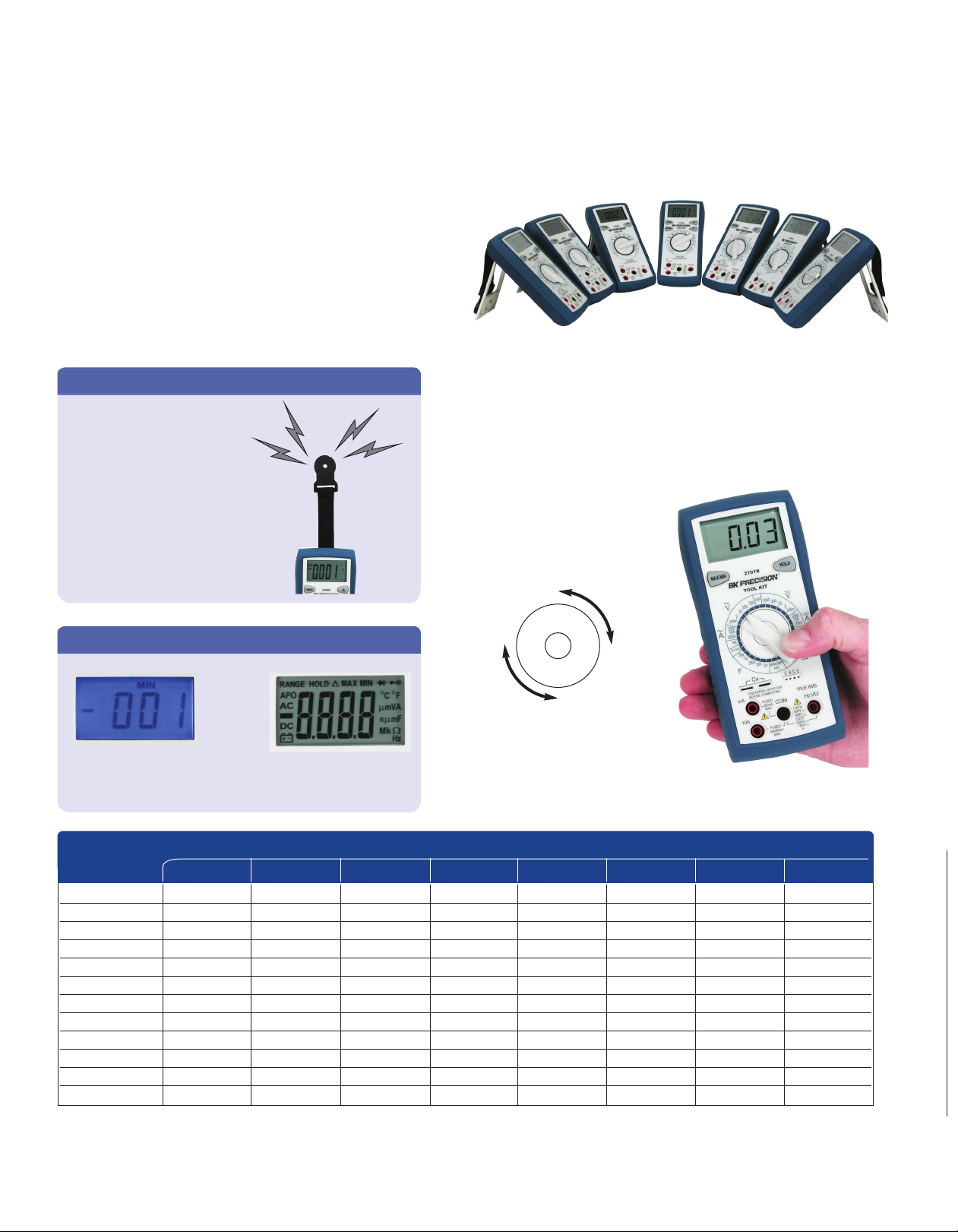
Magnet ic Hanging Strap
Single-handed operation
The ergonomic design allows both left and right handed users to rotate the
knob while holding the meter in one hand. While one hand keeps the probe
on the circuit, the other hand changes the meter’s function. This speeds up
troubleshooting because you don’t have to locate the probe point in the
This convenient feature allows you to
hang your DMM on any magnetic
metallic surface freeing up your
hands for troubleshooting.
circuit again.
Bac k Light / Easy-t o-Read LC D
Model 2706B Models 2709B & 2712
Ultra-bright blue LCD
back light for low ambient
light measurements
Large easy-to-read LCD
with green LED backlight
Features
2712 2709B 2708B 2707B 2706B 2705B 2704C 2703C
Ranging Auto/Manual Auto/Manual Auto/Manual Manual Manual Auto/Manual Manual Manual
True RMS AC + DC √√ √ - ---
Current 10 A AC/DC 10 A AC/DC 10 A AC/DC 10 A AC/DC 200 mA AC/DC 10 A AC/DC 10 A AC/DC 10 A DC
Capacitance to 40 uF to 66 mF - to 20 uF to 20 mF - to 20 uF Transistor Test ---√ --√ -
Frequency Counter to 500 kHz to 66 MHz - to 20 MHz to 40 kHz - to 20 MHz Temperature ----√ ---
Logic Probe ---√ --√ -
Backlight LCD √√--√ ---
Analog Bar Graph √ - √ ----Battery Test -------√
Auto Power off √√√- √√--
➱
models
Page 2 of 2
v041113
www.bk pre c i sion. c om
 Loading...