

Page 1
I
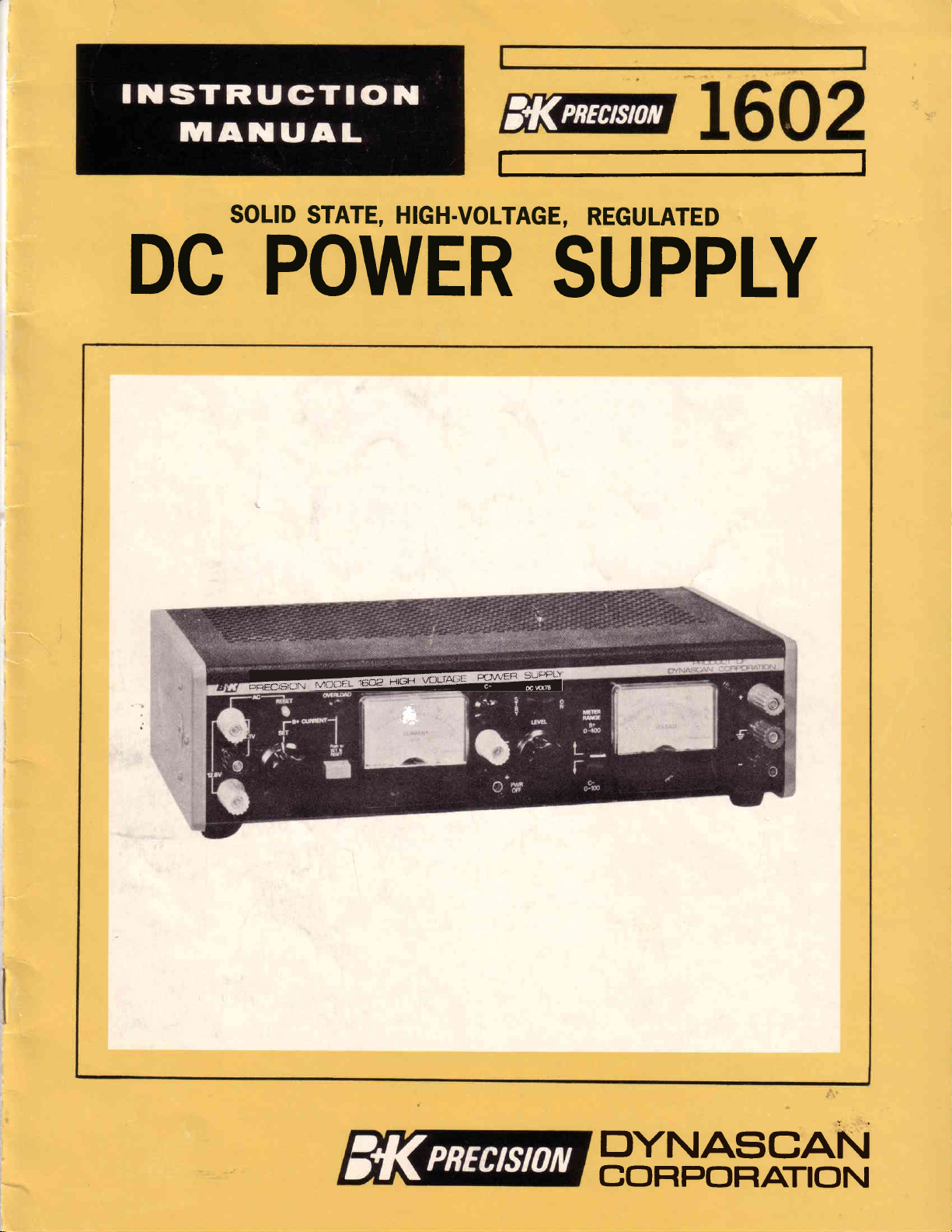
SOLID
DC
POWER
STATE, HIGH.VOLTAGE,
REGULATED
SUPPLY
i
trIYNASCAN
COF|POF|ATION
Page 2
CONTENTS
PAGE
SPECIFICATIONS
FEATI.JRES
INTRODUCTION
OPERATING
OPERATING
APPLICATIONS
CIRCI.JIT
MAINTENANCE
CALIBRATION
REPLACEMENT
FUSE
WARRANTY
CONTROLS
INSTRUCTIONS
DESCRIPTION
.
.....7
. . .I1
.....13
.
.14
..
Cov-
3
3
4
4
5
l3
3
Page 3
SPECIFICATIONS
FEATURES
INPUT
4OOV
VOLTAGE
DC
Output
Output
Grrrent
SUPPLY
Voltage:
Current:
Limit
ment/Protection:
Load Regulation:
Line
Regulation:
Noise
& Ripple:
IOOV
DC
SUPPLY
Output
Output
Load
Line
Noise
Voltage:
Current:
Regulation:
Regulation:
Ripple:
&
Protection:
6. 3VAC
(Non-Adjustable)
Output
Output
Voltage:
Current:
Protection:
1 2.6V
(Non-Adj
AC
Center-Tap
Output
Output
Voltage:
Current:
Protection:
METERING
Voltmeter (2
Milliammeter:
DIMENSIONS
NET
WEIGHT:
Adjust-
ustable)
Supply
Ranges):
(Overall);
-
105
I25VAC,
-
0
400V,
continuously
able.
-
0
20OmA.
lOmA
ously
rent
to
200rnA,
variable-sets
to
shut-down
put.
0.1%
at high
end.
0.t%.
Less
than
lOmV
0 - 100V,
continuously
able.
-
0
2mA.
r%
lVo
Less than
Current-limiting
6.3V
3.5A
Thermal
6.3V
3.5A
Thermal
0 to 400V
to l00V
0
Range
0 to
14-118"
I I lbs.
1OmV
!57o,
full
primary.
continuous.
circuit-breaker.
!5%,fuII
primary,
each
center-tap.
continuous.
circuit-breaker.
DC
!37o.
only),
DC
only), !3%.
selected
200mA
supply
(monitors
only),
x
3-7
f
(400V
(100V
8" x 10"
Hz
60
vari-
continu-
trip
cur-
supply
out-
peak-to-peak.
vari-
peak-to-peak.
resistance.
load;
I IOVAC
I I0VAC
load;
side
to
supply
supply
by switch.
400V
t3%.
deep.
Fully
solid
state,
tors
and
solid
or
Current
diodes
state
stabilization
Umiting/Overload
instrument
shutdown,
on.the
and load.
loads
B+ output.
The
protected
are
Simplified
current
shutdown
connections
application
press
the
the
O400V,
button
desired
G200mA:
over.entire
required.
G100V,
gver.
tloating
oglpgt
400V
6.3VAC,
Fully
G2mA:
entire
output.
or
can
output.
I2.6VAC
utilizing
and
construction
delay,
against
fully
adjlstable
6.3VAC
Cunent
or
output
of
short
and
setting
wjth
-rgnge
regulated
Output
rang€
Can be
be
used with
sources.
Dual
Meters:
supply
voltmeter
voltage.
damage from
one
current
by requiring
Two
Voltmeter
B+ and
tion
with
Standby-DC
external
Allow
current
can
Both
drain
also
meters
excessive
Range:
only
one
Ranges:
C: supplies
a minimum
On
loads
Switch: Disconn€cts
without
tings.
Pilot-
Lamp:
supply
Mechanical
increased
Lights
on.
is
he-Regulator:
progressive
in
improves efficiency
low
voltage
Floating
tive outp_uls
external
Reverse
damage from
power
Attractive,
when
E"ry
rgadthat
might
output.
outputs:
of
DC potential
?olarity
reverse polarity
source.
Functional
more
than
t9.
Ope_rate:
Simplified
damage
Permit
the
hotection:
one
All
operation
equipment.
integrated
one
SCR. Among
are
dependability,
ruggedness,
circuits,
compact
Protection:
overload.
Resistive
by a resettable
Shutdown
point
on
Output
with
CT,
to
be
have
Pre-settable
from
l0rnA
protects
12.6{IAC
and
limiting
the
circuit
Setting: Permits
without
voltage
circuit
adjust
the
current meter.
single
g
output
voltage
a single
used
either
disturbing external
settings;
to
output
the
CURRENT
voltage
continuously
control;
at
levels.
all
continuously
control;
independently
polarity
G3.5A: Independently
B+
supply
be
monitored
switched
output
to
monitor
overload protection
loading.
Simplifies
current
adjuitment.
0-400V
respectively
effort
to
and
provide
the
user.
Gl00V
the
disturbing
up to
steps
less power
as
referencing
supply
-B+
grounds.
or
B+
voltage
indicate
supply
as output
is converted
and the
at
the
Prevents
connections
tlesign:
power
controls
Permits
supply
is
required.
are
helps prevent
identified
-
silicon
the
no
transis-
advantages
warm-uf
time
size.
Protects
automatic
to
200mA
heater
load
current
provided
the
C- supply
windingdinb
breaker.
setting
load
does not
terminals.
require
sirirply
SET controi
adjustable
no
range
switching
adjustable
indepehdently
of
the
referenced
0400V
to the
floating
voltage
simultanebusly.
the
shutdown
maximu=m
DC
or
glance
a
rectifier
is increasea.
positive
C-
against
to
stacking
operator
and
bias
prevent
to
ranges
supplies
iurrent
that
voltage
to
heat
or
supply
accidental
an
external
of
-
and
easy
mistakes
The
iupply
setting
for
the
resolu-
from
set-
the
inis
nega-
to
any
units
of
and
B+
tb
AC
B+
is
at
to
Page 4
INTRODUCTION
The
Supply
pr6vities regulated
bZOOmn
currents
mance,
excellent
voltage
-solid
fully
Unlike
have 3 indefendent
and
circuits,
versatile,
a
is
G100V
and
of 6.3
operating
^choice-
power
DC
siate circuits,
supplies,
some
etc.
and
Precision
K
B &
High
Model
laboratory
voltages
DC
I2.6VAC
ease, and
for most applications
source.
the user
supplies
1602
quality
and
at G2mA;
at
special
well'suited
It
is
type
tube
can
for
currents
and
0-3.5A.
features
circuits,.
rectify
powering digital/analog
Voltage
instrument
of 0-400V
voltages
AC
high
The
make
requiring
for,powering
hybrids.
and
the AC.source
OPERATING
Power
which
at
and
perfor-
an
it
high
a
Following
of 1602:
o
o
o
o
is a
Service
equipment,
tors,
Factory
or individual
Engineers
totypes
Electronics
periments
Technicians:
vacuum
Technicians:
and
CONTROLS
of some
list
or
tubes
assemblies
and l:boratory
experimental
Instructors
basic and
in
of the
Powering
individual
both.
or
Powering
advanced
popular
most
voltage
high
circuits
during
equipment.
and Students:
consisting
complete
testing
Technicians:
electronics.
6
og
@
applications
solid
transis-
of
equipment
factory.
the
in
Powering
Laboratgry
8
state
pro'
ex-
l.
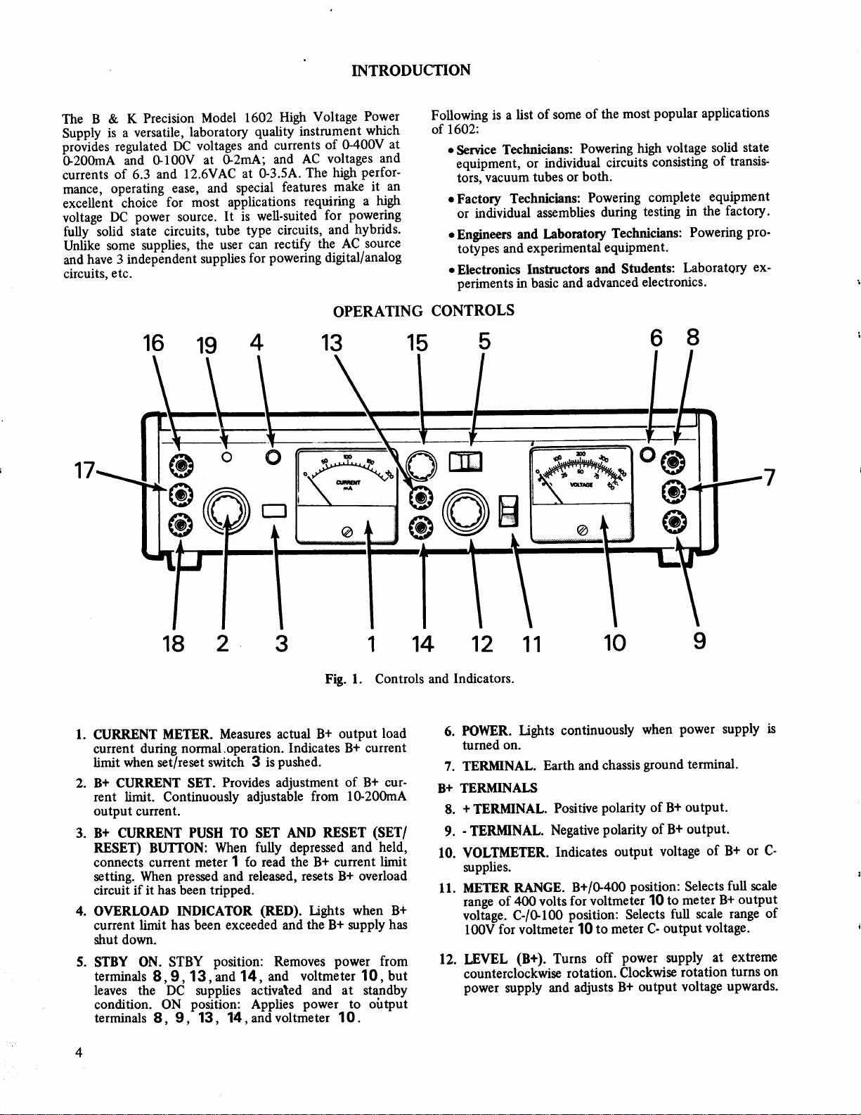
CURRENT
current
limit when set/reset switch 3 is
2.
B+ CURRENT SET.
rent limit.
output
CURRENT
3.
B+
METER.
during
Continuously
current.
RESET) BUTTON:
connects cunent meter
setting.
circuit if it
4.
OVERLOAD
current
When
has been tripped.
limit has
Measures
normal.operation.
Provides
PUSH
TO SET
When
1
pressed
INDICATOR
and released,
exceeded and
been
strut down.
5.
STBY
terminals
leaves the
condition.
terminals
STBY
ON.
8, 9, 13, and
DC supplies
ON
8,
position:
posifion:
9, 13, 14, and
Fig. 1. Controls
actual B+
Indicates Bt
pustred.
adjustment
adjustable
output
from l0-200mA
AND RESET
fully
depressed
fo read the B+ current
resets B+
(RED).
14,
Lights
the
B+ zupply
Removes
and
power
voltmeter 10, but
load
current
of B*
(SET/
held,
and
limit
overload
when B+
from
activated and at standby
Applies
power
to oirtput
voltmeter 10.
B@e
14
and
cur-
has
12
Indicators.
POWER.
6.
turned on.
7. TERMINAL.
TERMINALS
B+
+
TERMINAL.
8.
-
TERMINAL.
9.
VOLTMETER.
10.
srpplies.
METER
ll.
ranse
vollage. C-/G100
100f
12.
LEVEL
counterclockwise
power
Ughts
RANGE.
400 volts
of
for voltmetei
(B+).
supply
11
continuously
Earth and
Positive
Negative
Indicates
Turns
and adjusts
chassis
polarity of
polarity
B+/G400
voltmeter
for
position:
to meter
10
off
rotation.
@
when
ground terminal-
B+
B+
of
output
B+
voltage
position:
to meter
10
output
C-
full
supply
Selects
power
Clockwise
output
power supply
output.
output.
or
of B+
full
Selects
scale
output
$+
range
scale
voltage.
extreme
at
rotation
voltage
turns
upwards.
is
C-
of
on
Page 5
C-TERMINAI,s
-
13.
TERMINAL.
+
14.
TERMINAL.
15.
C-
CONTROL.
terminals
rotation.
meter
10
13
Output
when
C-lGl00V
16.
& 17.
6.3VAC
minals.
Negative
Positive
{,{gsts
't4
and
voltage
METER
position.
TERMINAIS.
Protected
polarity
polarity
C- output
from
0 to-100V
is
RANGE
by
breaker
odtput
of
output
of
voltage
witf,
monitored
Switch
6.3VAC
19
C- supply.
C_
supply.
between
clockwise
on
1l
output
Voltis
in
rer-
16.&
19. AC
protects
16,17
NOTE:
18. 12.6VAC
minals.
RESET.
At17
protected
convenience
accidental
AC
Protected
Circuit
against excessive
and
16,18.
and18
short-circuits
outputs
TERMINALS.
by breaker
breaker
overloads
6.3VAC
by
an internal
and minimum
16
,
is
17 and
l2.6VAC
19
in series with
between
available.
use
16,
This
fuse.
For
down-time
the
breaker-protected
18.
output
terminal
terminals
output
maximum
due
ter-
16
is
to
l.
Turn off
AC
outlet,
counterclockwise,
2. Connect
outlet.
a.
Use
only
that
the power
good.earth.
electrical
m_ust
be used,
adapter
b. If
a
circuit
fixed
using
the_C-
voltage (Step
Turn
gn-lhr_
control
POWER
4.
Determine
device
strutdown
a. Push
b. Release
c.
d.
In
OUTPUT.
rygy.not
SET/RESET
sensing
1Z
indicator
to
and
B+
CURRENT
down
meter
-
Turn
voltage.
If
the
with
a low
the
overload
to
the
current
circuit
certain
circuitry
maximum
SENSING
proceed
(a)
Set
as
the
position.
the power
by
the power
supply
rotating
until
cord to
WARNING
polarized
a
supply
ground
shock.
lf
is attached
bias,
be
for
current point
1 .
the
LEVEL
load
setting
_
does
voltages
be
be
under
test
always
supp-ly
6-d).
qower supply
slightly
the
hold
conditions
accomplished
clockwise
6
maximum
powered
that
value
the
set/reset
SET
set/reset
(B+)
safe load
current
circuit
in
steps
in small
not
trip
gre,ater
buttbn.
3
will
described
CIRCUITS,
follows:
STBY/ON
the
"clicks"
it
3-wire
chassis
prevents
and
a
2-wire
sure
the
good
to
a
requires
apply
first;
before
light.
safe
and
set
as follows:
control
as read
button
control
setting.
will
trip
6 and
during
NOTE
of
high-line
ihan
by simply
(Thisis
under
page
13.)
switch
S
OPERATING
plugging
before
LEVEL
a
the
by rotating
bu_tton
current
If
steps
normal
control
off.
105-125
outlet.
to
ground
earth ground.
past
-
the
2
3 .
when
7.lfio,
Oue
volt
This
is
connected
danger
3-wire-
wire
application
required
applying
the-.,click".
load
current
automatic
3 and
for
the
on
the
12
to
is unknown.
the
setting
pow6r
until
the
operation.
voltages
100V,-resetting
pushing
t6
the
CURRENT-VCE
Should
to
this
the
it into
fully
12
Hz
60
AC
assures
to
a
from
adapter
of
the
of
a
voltage
the
Ii'+
the
LEVEL
The
for
the
current
adjust
desired
CURRENT
the
is too
increair'tf,.
the
shut_
desired
start
low,
is apphed
overload
or
B+
thJ
qr-"VCE
occur
STBY
INSTRUCTTONS
an
(b)
(c)
If an
exists,
At
very
output
activate
desired
The
lamp
stated
5. Connect
powered
a.
connect
the
the
b.
Connect
the
the
If
c.
is to
terminal
If the
is to
terminal
If
of
but
connect
device
d. Follow
u.silg^ plus
Ih.r
independent
a.bias
circuit
supply
2.
e.
Connect
als
quired.
Push
the
the B+
CURRENT
to the
Release
STBY/ON
supply
19
in
B+
B+
the positive
neither
the
SET/RESET
CURRENT
desired
the
overload
the
supply
low
output
voltage
the
QI-VCE
B+ output
will
will light.
(a),
(b),
powe_r
the.
with
test
th9 positive
device
being
supply.
the
device
being
supply.
be
^the
8 to
negative
be^the
9 to
the
device
the
chassis
a
separate
to
the
the.above
(+)
13.
C-
-supply
of
voltage
16
which
reference,
is connected
the
17
,
METER
5to
negative
ground
SET
1
current limit.
SET/RESET
postiition..
ON
in
the
will
between
shutdown
and
polarity
the
polarity
the
positive
being
circuitry
shutdown
currents,
sensing
is reached
To reset,
(c)
above.
supply
leads
as follows:
polarity
powered
polarity
powered
ground
ground
ground
ground
or
powered
of the
test
terminal
procedures
terminal
NOTE
and
the
each
other.
is negative
(+)
the
to this
AC
andlor
1G
button in
3
at least
2to
if not
already,
3
button
being
as
normal.
decreasing
l50V
to
circuit
on
VOLTMETER
and the
simply proceed
output
of
reference,
of
reference,
the
lead
14
B+
When
terminal
reference.
voltage
18lto
,
to
high
to
the
high
to
the
the
device
terminal
the
device
terminal
negative
needs
device
from
7 of
for
and
supply
a iircuit
with
and
adjust
50mA
reset
and
and
return
powered
the B+
400V
before the
OVERLOAD
the
device
voltage
(+)
teririnaf
voltage
(-)
terminaf
being
j_lrmpei
-
7
.
being
conneJt^
T.
polarity
grouniled
to
be
needs
grounding,
the
chassis
the
B+ supply.
the
C_
minus (-)
are
entirely
requires
respect
14- of
sources
the
Refer
device
to
the
to Fie.
on
may
10.
as
being
input
of
8 of
input
of
g
of
powered
the . (+)
powered
the
o
input
of
the
supply,
teiririir_
the
C-
(termin_
if ;;_
Page 6

sr
GTN
H
H6Bm"
6.
Return
and
a.
b. Turn C-
c. Set
d.
When a fixed bias is
test, always
level.)
If the
7.
point,
supply will
meter
to normal
a. To reset
b.
the
STBY-ON
output
set the
METER
Set
adjusting
C- supply
control
the METER RANGE
when adjusting B+ supply
Turn LEVEL
reached.
perform
load
B+
the overload lamp
shut
will
10
operation
set/reset
tent,
If
following
supply again.
(l)
(2)
the
button
this will restore
the overload lamp
Reduce
Reduce
control
Switch 5
follows:
voltage
RANGE
as
Switch
output.
until desired
15
switch 11
output .
control
clockwise
12
NOTE
required
Steps
current
down
to zero).
drop
follows:
as
power
3 .
techniques before
the load
the voltage slightly
12 .
for
a and b
exceeds
4 will light,
(cunent
Restore
supply,
If the overload
normal
operation.
remains lit, use one
current.
Flg.
to the ON
to C-l0-
100V
voltage
is
to B+/G400V
until voltage
a circuit
the
meter
press
resetting the
under
first. (C-
current shutdown
and
1 and volt-
power
the
and release the
was
the
with
Typical Vacuum
2.
position
when
reached.
is
bias
the
B+
supply
intermit-
of the
power
LEVEL
Circuit
Tube
(3)
lncrease
B+
load current
used, but, if
the
the current
(4)
Check
incorrectly
(5)
Refer
equipment
Some
results in
which
initially
the
STBY-ON
full
reduce
overload
gadually
to
c.
d.
e. Refer
applied.
overl,oad
operatingvoltagepreviously
the voltage setting
charge;
power
If the
correct
determine
remove
To
the voltage
STBY-ON
Application.
the strutdown
CURRENT
maximum
switch
and
to allow
this eliminates
current
to
is
the current
safe
limit
the bias
set.
NOTE
to
has a
a surge
When
circuit may
placed
is
then
the capacitors
supply continues
setting,
reason
the
power
from
or current
switch
NOTE
5
under
point
control
SET
unknown,
further.
setting
under
NOTE
powering such
bring
for the
to the STBY
this
limit
load current,
to determine
4d,
highly
current
activiate
the
in
set.
before
the output
the surge current.
check
overload.
the load
shutdown
page
4-d,
slightly
2 .lt
technique
is
Page
capacitive
when
ON
If this
the equipment
in
to shut
the load
without disturbing
position.
5.
with
normal
the
may be
already
not increase
do
if
5.
input,
power
equipment,
when the
position with
occurs,
resetting
level
dodn
circuits
settings,
the
for
set
it is
is
the
up
at the
set
to
the
Page 7

APPLICATIONS
General
used
be
instrument
This
circuits
electronics manufacturing,
and
are
voltage
suitable
output
Powering Tube
Fig.2
voltages in
l. Connect
2.
3. Connect
and devices
electronics
fully adjustable
AC iource
for most applications
high voltage
shows
for
17
l2.6VAC
Connect
C-supply.
(-)
terminal
may
education.
Type Circuits
the 1602 being
a typical vacuum.tube
the filament
6.3VAC
heater
the
the
the
in
over
remains fixed.
supply.
heater operation
voltage
grid
resistor to
(+)
terminal 14
of
9
the B+
power a vast assortment
to
fields of
electronics
The l+
their
requiring
used to
the tube
of
is
supply.
electronics
design
and C-
full range,
flexibility
This
a single
supply
RF amplifier
to terminals
or
required.
(-)
the
terminal
the C- supply
of
supply
while
to 16 and
servicing,
engineering,
outputs
low
the
makes it
or multiple
operating
the
stage.
and
16
18 if
13 of
to the
of
the
4. Connect
supply
of
5. Connect
B+
ground t6rminalionnection
the B+ supply
experimentJ,
supply inputs.
With the meter
C- control
Before
current
control
voltage
S+
current
the
either increase
current
to
refer
the B+
to
the tube.
the common
supply.
for the desired
the S+
set/reset
for
the maximum
level may
overload
drain
NOTE
lead to
provide
point
This
7
between
may
such
switch
output
button
B+ current
the
increasing
by
under
the
power for
lead
also
is
for strock
,
ground
be used
not
positive
as
the
C-/G100V
in
level.
bias
voltage
adjust
and
output
increased
be
4'D,
shuts
the
Page
circuit
(+)
terminal
plate
the
(-)
the
to
normally
hazatd
the
and
during
grounds
adjusted,
is
the B+
current
to
down
or decrease
set,
output
C-
5.)
and
terminal
connected
prevention.
(-)
terminal
some
position,
CURRENT
desired.
required
the
the
voltage.
of the B+
I
screen
of
9
to
types
floating
and
adjust
press the
Now
level-
output,
B+
output
the
(Also
grid
the
the
The
9 of
of
the
B+
SET
the
If
GIN
H
=
t-)
I
\
SIG OUT
Vcc
g6:gB6Em"
Fig. 3.
Typical Triinsistor
Circuit
Application.
Page 8

Powering
Transistor
Fig. 3 shows
transistof
amplifier circuit.
l. Connect
terminal
Connect
2.
terminal
terminal 7.
Type Circuits
the
Power Supply
1602
the Vcc lead
of the
8
B+
the common
the B+
9 of
of
supply.
lead of
supply
being
the
circuit
the circuit
and to
used
to
to
to
the
power
(+)
the
the
ground
(-)
a
In some circuits
line which
(+)
the
to
the
chassis
means the
terminal
ground
of the
8
connected
is
terminal should be connected
supply.
B+
various methods to connect the 1602
different
doubt which
is any
no
damage
to the
chassis
equipment
will result
ground
power/ground
configurations.
supply lead is common
if a separate lead
terminal
is
7 .
positive
to the
Fig. 4
to
accommodate
to the
connected
shows
If there
chassis,
from
Vcc
the
the
EQUIP},IENT
BEING
POWERED
EQUIPI\4ENT
BEING
POWERED
Other Educational
The student
supply
described
supply
electronics.
of resistance,
strips
in
powering
for
for
all other
can be used to
In
learning
strated with the
and current
ments. Fig.
experiments
Using
Whrn
for testing
voltage
required
reference
Fig. 6 shows
connections
prevent
to
numerous
The
ditional
supplies are
external
an
simultaneously
5
that may
Two
Supplies
two
separate
equipment,
and
current limit for
by each
point
some
when
reverse
colors
protected
voltage
must
for
8
Uses
an electronics
equipment
applications. In
course may
and
circuits
addition,
conduct experiments
Ohms law, for example,
voltage
supply.
and current are easily
Being able to observe
geat
is a
shows some examples
be conducted.
for
Two B+ Voltages
B+ voltages
two
load
be common
typical
using
polarity
connections
the
test
from
source
are required
supplies
each
supply
requirement.
between the
examples
two
units.
connections
can become
leads will
reverse
such as the
may
proper
of
Take
be helpful.
polarity
other
Fig.4.
Power
the
use
previously
as
the
fundamental
in
power
power
the relation-
demon-
both voltage
aid
such experi-
in
of
the types
simultaneously
be used.
Set
independently
Only the
circuit
two supplies.
power
supply
precautions
extra
in such situations.
confusing.
Ad-
The'power
damage from
power
supply.
Supply
of
the
as
Output Situation.
Although two
situations,
operated
supplies
it
not recommended
is
in series
for
avoid shock hazards,
power
to
the
entire power
the
supply output
supply
may
be used safely
voltages higher
not
do
connect
terminals;
chassis
at a
that
the supplies
than 400V. Also,
in
ground
both
doing so
potential.
high
the
above
terminals
place
may
be
to
Page 9

OBSERVE
CHARACTERTSTIC
OF DIODE
@oo
E@=
cEl
E@e
MEASURE
VARY
Vnt
ETN
&
I
MEASURE
Vot & I
I
VARY
Etrv
CHARACTERISTIC
OF
ZENER
II{EASURE
VARY
Eru
DIODE
VVnt
&
Fig.
5.
Typical
12- tr*
r1=
11+12
Laboratory
BASIC
#fu,
tr*
sfu;
=
tT*
Classroom
CURRENT
*-.
-
Experiments
rnr
-a>
^
Using
DIVTDER
r1
the
1602 Power
OBSERVE
IJAII
OHMS
E
^-T
Supply.
Page 10

&-l
frl
B.
oo
AZ
E{
zo
HUFl
E ZX
A{HF]
HF]B
Dmo
olA
F]
H
zo
FlUrl
zze
AHfrl
HF1
B
Dmo
olA
Fl
t\
olo&
oc!
ql
Fl
++o
)r^
Fl>
Aro
AN
.J an
(Dv
crt
fi
frt
B.
oo
tuz
tu
oxo
oo
c\
+ol
Ol A{
&-l
F1
B.
oo
tuz
F
zo
F]OF]
zZX
AH14
xtrlB
Dmo
olA
Fl
F{
zo
E](JE]
zze
AHF]
xrqB
Dmo
E1
a
l\H
o&ao
4<)
o
N
+OU
6dd
|
+-lr'l
|
I
tGrl
F]
>
AO
AO
DN
(n+
ficr
Fl
B.
oo
g4Z
hn
tn
H
N
YfrB
ofi
Yrl
;.
F
o
F
ch
q)
a
X
80
a
Or
F
p
cg
d
()
g
o
GI
a
A{
a
'
o
ut
c)
g
A
=
q)
'
o
o
B
oo
tr
ct)
l0
&-t
F]
B.
oo
tuz
160.6
+-.|"
|
I
lf,---r-]
o,l
fi
Fl
5;
O1
Z
66d
|
+-{t,
|
l[---r-1
>r
H^
A>
AO
D|n
a-
&-l
H
B.
oo
tu2
\o
ri)
fr
I
Page 11
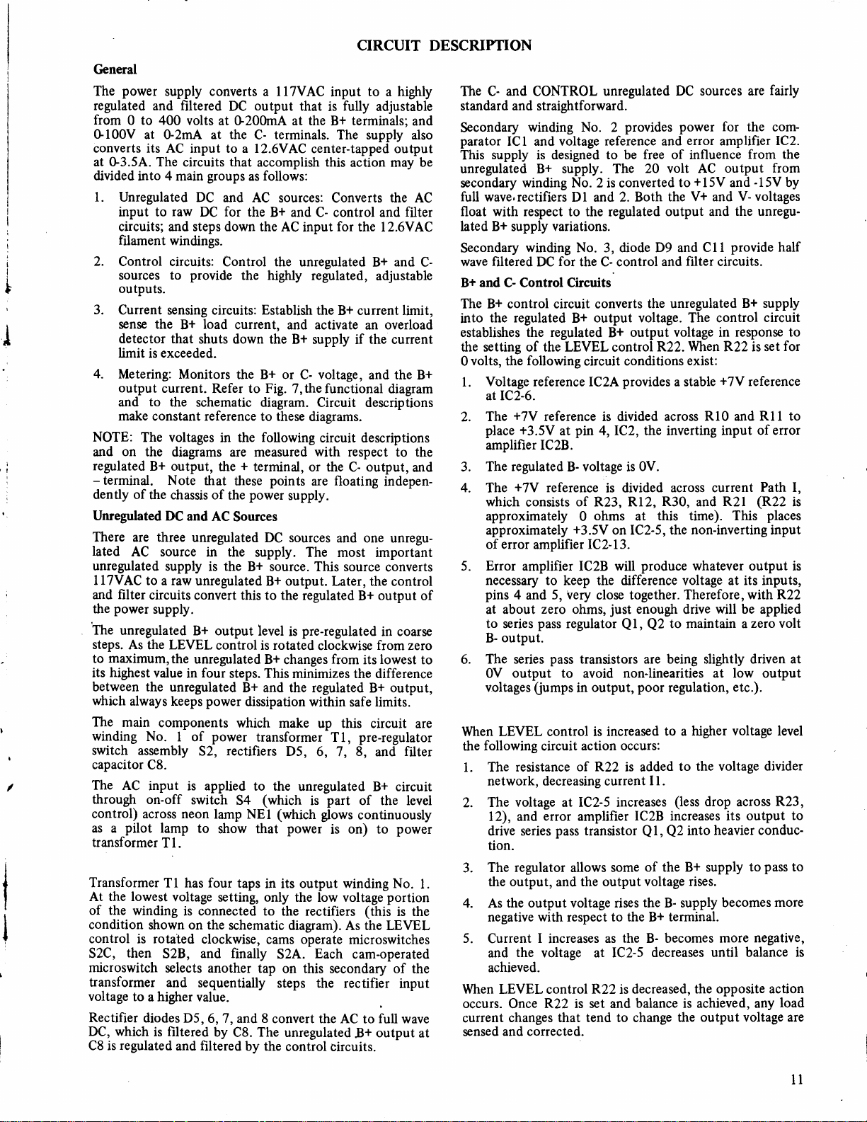
C'eneral
power
The
regulated
from
G100V
converts
at G3.5A. The
divided
l.
Unregulated
input
circuits; and steps down the
filament
2.
Control circuits:
sources to
outputs.
3.
Current
sense the
detector that
limit
4.
Metering:
output
and
make
NOTE:
and
regulated
-
terminal.
dently of
Unregulated
There are three
lated
unregulated
I ITVAC
filter
and
power
the
The
unregulated
steps.
maximum,the
to
highest
its
between the
which
The
winding
switch
capacitor
The
through
control)
as a
transformer
Transformer
At the lowest
the
of
condition
control is rotated
S2C,
microswitch
transformer
voltage
Rectifier
DC, which
regulated
C8 is
supply converts a llTVAC
and
filtered DC
to
0
400 volts
at 0-2mA
its AC input to a l2.6VAC
circuits
into 4 main
to raw
exceeded.
is
current.
to
constant reference
The voltages
on
the
B+ output,
the chassis of
AC source
to a raw
circuits
supply.
As the LEVEL
value
always keeps
main
components
No.
assembly
C8.
AC
input
on-off
across neon
pilot
lamp
T1.
Tl has four
winding
shown on the
then
S2B,
to
a higher value.
diodes D5,
is filtered
groups
DC and
DC
windings.
provide
sensing circuits:
load
B+
shuts down the
Monitors
the
schematic diagram.
diagrams are measured
Note that
DC
and
unregulated
in the
supply
selects another
and sequentially
is
unregulated
convert this to the
B+ output
unregulated
four
in
unregulated
power
1 of
52,
applied
is
switch
to
voltage
is connected to
clockwise,
and finally
6, 7, and 8
and
filtered by the
output
at G200mA at the
the
at
that
for
Control the
Refer
in the
the
the
AC
the
control is rotated
steps.
power
rectifiers
lamp NEI (which glows
show that
setting,
schematic diagram).
by
terminals.
C-
accomplish
follows:
as
AC sources:
the
B+ and
AC
the highly
Establish
current, and activate
the B+ or
to
Fig. 7,the functional
to these
following
+
terminal, or the
points
these
power
supply.
Sources
DC sources
supply.
B* source. This source
B+ output.
level
B+
changes
This minimizes the difference
B+ and the regulated
dissipation within
which
make
transformer
D5,
to the
(which
54
power
taps
in its
only the low voltage
the rectifiers
cams
S2A.
tap
on this secondary of
steps the
convert the
The
C8.
unregulated
control circuits.
input
that
is
B+
The supply
center-tapped output
this
Converts
C- control and
for
input
unregulated B+ and C-
regulated,
the B+ current limit,
B+ supply if
voltage,
C-
Circuit descriptions
diagrams.
circuit descriptions
with
are floating
and one
The most important
Later, the
regulated
pre-regulated
is
clockwise
from
up this
Tl,
6, 7,
unregulated
part
is
is
output winding No.
operate
Each
AC to
CIRCUIT
to a highly
fully
adjustable
terminals;
action may be
the
an
the
and the
respect to the
output,
C-
B+
its
safe
pre-regulator
8,
of the level
continuously
on) to
(this
As the LEVEL
microswitches
cam-operated
rectifier
!+
and
also
the AC
filter
l2.6VAC
adjustable
overload
current
diagam
and
indepen-
unregu-
converts
control
output
in coarse
from
zero
lowest
output,
B+
limits.
circuit are
filter
and
B+ circuit
power
portion
is the
the
input
full
wave
output
DESCRIPTION
The Cstandard and straightforward.
Secondary
parator
This
unregulated B+ supply. The
secondary
full
float
lated
Secondary
wave filtered DC
B+ and C- Control Circuits
The B+ control circuit converts
into
establistres the regulated
the setting of the LEVEL
B+
0
l.
")
3.
4.
5.
of
6.
to
When LEVEL control is
the
2.
3.
l.
4. As
5.
When LEVEL control
occurs.
current
at
sensed
and
CONTROL
winding No.
ICI and voltage
supply
wave,rectifiers
with
B+
the regulated
volts,
Voltage reference lCzA
atlC2-6.
The
place
amplifier IC2B.
The
The
which
approximately
approximately
of error
Error
necessary
pins
at about
to series
B-
The series
0V
voltages
following
1. The
network, decreasing current
The
l2),
drive series
tion.
The
the output,
negative
Current I increases
and
achieved.
is designed
winding No.
respect to the regulated
variations.
supply
winding No. 3, diode D9 and
following
the
+7V
reference
+3.5V
regulated
+7V
reference
consists
amplifier
amplifier lC2B will
to keep the difference voltage at its inputs,
4
5, very
and
zero
pass
output.
pass
output
(iumps
circuit
resistance
voltage
error
and
regulator
the output voltage rises
with
the
voltage at IC2-5
R22 is set and
Once
changes that tend to change
and corrected.
unregulated
provides power for
2
reference
to
be
2 is converted
Dl and
for
l+
pin
at
B- voltage is
of
+3.5V
ohms,
regulator
to avoid
at
pass
allows
and
respect
2. Both the
the C- control
output voltage. The control
output voltage in
B+
control
conditions
circuit
provides
is divided
4,IC2, the
is divided
Rl2,
R23,
ohms
0
on IC2-5, the
lC2-13.
close together.
just
Ql, Q2
transistors are being slightly driven at
in
of R22
lC2-5
amplifier
the output
non-linearities at low output
output,
increased
action occurs:
is added
increases
transistor Q l,
some
to the
the
as
R22
decreased, the
is
DC sources are
error
and
free of
20 volt AC
output and
and filter circuits.
the unregulated
R22.
a stable
across
inverting
0V.
across current
R30,
this time). This
at
produce
enough drive
to maintain a
poor
regulation,
to a
I1.
(less
IC2B
increases
Q2
of the B+ supply
voltage rises.
the
B- supply
terminal.
B+
B- becomes
decreases until
balance
amplifier
influence
+15V
to
V+ and
Cll
When R22
exist:
+7V
RlO
and
non-inverting
whatever output is
Therefore, with
will
higher voltage level
to the voltage
drop
heavier conduc-
into
more
opposite action
achieved, any
is
output voltage are
the
output
and
V- voltages
the unregu-
provide
B+ supply
response to
and
input
R2l
be applied
etc.).
across
its
becomes
fairly
the com-
IC2.
from the
from
-15V
by
half
circuit
for
set
is
reference
Rl l to
of error
Path I,
(R22
is
places
input
R22
zero volt
divider
R23,
output to
pass
to
balance is
to
more
negative,
load
ll
Page 12

ri
H
N
r\
&
14
rl
NN
ao
r*:
ti
Flr
E6
lO
d
crl
ot)
a
Er
H
U
&
H
o
tl
o
&
(\
o
F
z
o
C)
c€
A
cl
tr
o
o
)
lJr
f-
a0
tr
t2
(n
F]
C)
fr
o
a
H
q
C)
o
o
H
H
$
H
&
z
D
*g
?8
?8
EE
*
(_r"
o
Ee
p
Page 13

The C- control
the
into
listres
the output
BIAS control, R35.
The voltage reference for
and R34.
for
source
of
the control setting.
voltage
across
nal resistance
fu
that the reference
biased so that
point.
If the load on
attempt
output
The opposite effect
Overload description:
Current-VCE
The
comparator ICl, overload
resistor Rl.
sttuts down the
The current sensing
developed across
drarvn.
non-inverting
The
voltage
Whenever
Rl that
input
at output
so
Q3,
are absorbed
D21
12
increases,
to
current, which restores
main
The voltage across this resistor
inverting input,
source,
of the
circuit converts
regulated
Reference
R35.
the
output voltage will
increases above its
drops to draw more
its voltage never
the output
drop. This will
Sensing
components
This
input
R5, the
output load
the
greater
is
comparator, ICl, a
pin
7.
output
C-
level
diode
wiper
The
Any variations in the
across R34, because
the
voltage drop across R34
voltage
occurs
Resistance-limited.
Circuits
circuit monitors
B+ supply
resistor, Rl,
when exactly
it
of
the
ph
Bf
than the
This output
in
the
unregulated
voltage. This
response
in
this circuit
D21 acts as a
of
stays constant. Diode
increases,
turn
the
as
the
switch
the load
if
comparator,
3,
is connected
current
current
preset
to the setting of the
consists
R35
connected to the base
is
always be .6V less than
reference voltage,
current.
drops below its reference
the output voltage will
on harder,
Q3
the output voltage.
output load decreases.
current sensing circuits
SCR-1, and current sense
the
B+
current is exceeded.
is selected
200mA load
is
ph
to
limit
control.
produces
voltage on the
positive
the
drives
supply
C-
control
constant voltage
unregulated C-
as
also rises such
increasing the
load
so
applied
2,lcl.
a variable 0-1V
voltage across
a
lV signal
gate
estab-
of
D2l
,C14,
the
voltage
its inter-
D2l is
current
of overload
and
that IV
current is
to
inverting
appears
are
the
pin
regardless
supply. SCR-l
the overload
path.
another cir-
senses
above 200V.
and the
Operating
of D25 and
across
by the
power
the output
input
very
voltages.
and the
for either
exactly
is
the
current
current
R5.
accurately
meter.
output
meter
calibrated to
control
l0 of
of
read
devel-
I
This
operation
power
the
current
Ql
(Safe
developed
developed
equivalent
an
S.O.A. curve of
across
measure
proper
the
the
connects the
read on the
grounds
conditions the
a strutdown of
which
setting
SCR-I
switch
error amplifier
other
of all
provides
also
lamp to light.
when it is
Besides the
cuit comprised
the collector-emitter voltage of
During overloads
value of
collector-current
point
fuea) curve.
D24 is such
geater
R17
output current
pin
dissipation value
Q1.
the
output
Metering
Voltmeter
supply
the
B+
Range
is
Meter
proper series
G400V
Current
output
S+
oped
across
for
volt
limit,
switch
meter directly
control
corresponds to the
and turns it
IC2B, which inhibits its
inputs,
depressed, to
of
that
of ICl represents
2
Therefore,
preset
voltage
Ml
full scale, or G100V
meter
current. The
full
a
selects
shutting
ground
the
Set/reset
current-sensing
of
the collector-emitter voltage
out of
Ql
The avalanche
that
than
200V, a voltage is
adds to the voltage
across Rl. This summed voltage on
when
voltage
and current occurs.
is connected
or the C- supply,
switch
resistor to calibrate
M2
is
the
current
scale
meter
is actuated,
53
across the
a voltage from
current limit value
on.
SCR-I
down
path
which allows
switch 53 shorts across SCR-I,
replace the
NOTE
function,
R40, D25,D24, and Rl7
some reset
and
of
that
on
M
actually a
can shift the operating
Ql
its S.O.A.
for
sensing
breakdown
collector-emitter voltages
is
under the
this
summed voltage reaches
pin
3 of ICl,
directly
to
selects
full scale.
voltmeter
meter
measures the voltage
resistor,
reading. When
which
B+
current set
GlV, which
MAINTENANCE
following instructions
The
servicing other than
High
voltage
present
turned off.
result
on the fuseholder and
Always
fatal electrical
in
MAINTENA}ICE
power
This
service and does not require
unit malfunctions, use conventional
niques, such
defective
the unit should be
servicing
third
maximum DC
supply
component.
this unit keep the level control
rotation
is
voltage and resistor checks
as
If defective components
recalibrated. A note
(no
microswitches
voltage
below l60V DC.
contained
up to 500 volts
observe caution
shock.
provide
to
built
periodic
activated)
are for use by
in the operating
present
is
on-off switch
long,
maintenance.
troubleshootieg
on
safety:
R22
Remember that the
qualified
when
when the top cover
trouble-free
to
isolate
replaced
are
Whenever
below
to keep the
AND CALIBRATION
personnel
instructions unless
power
the
any time the.
If the
tech-
the
one
only. To avoid
you
are
supply
power
is removed. Contacting
pre-regulator
Use
P.C.B.
gain
To
screws
the
retaining bosses
locations
is operating.
supply
can supply up
insulated
has over 400V DC
at
rear and slide
adjusting
to the calibration
access
the rear of the
of
calibration
electrical
qualified
is
connected
shock, do
to do
Line voltage
to an
exposed
to 500V DC to
CALIBRATION
and
tool,
potential
top cover,
front lip
the
front
the
on
adjustments.
perform
not
so.
(120
VAC) is
the
lift the
Refer
even if
board.
remove the
top cover at
to Fig. 8
ac outlet,
high voltage could
exercise CAUTION-
maximum
at
adjustments,
then
of the cover
panel.
the
settings.
3
from the
for
l3
Page 14
l00v METER
l. Connect
output
ing-
2. Set
supply
Adjust
3.
an accurate, calibrated
terminals
the METER RANGE
to the
the
external voltmeter.
4. Adjust
l00V
l00V
on the
(R26)
CAL
13
and
C-lG100
C-
CAL
position.
control
potentiometer
voltmeter of the
14
,
switch
for exactly
15
1602
voltmeter
11
of l00V
of
capable
(R26)
power
to the
power
the
on the
100V
for exactly
supply.
read-
MAX.
OUTPUT
1. Connect
ADJ.
an accurate,
output terminals Sand
the LEVEL control
Set
to MAXIMUM.
3.
400v
l. Connect
the MAX. OUTPUT
Adjust
for
exactly 402 Volts
METER
CAL
an accurate, calibrated voltmeter
output terminals
2.
Set
the
METER
positlon.
3.
Set the
LEVEL control
to read exactly
4.
Adjust
400
CURRENT
Refuce
l.
2.
Connect
200mA
l0 watts)
1602
3. Adjpst
the
4. Adjust
for exactly
power
400V
Volts
on the voltmeter of
METER
the
an accurate,
in series with
to the
power
the
LEVEL
external
CURRENT
supply.
1602
supply.
ammeter.
2OOrnA on
CLTRRENT LIr\ilrT
NOTE: No
l. Set 2
Press
2.
the
release
load
connected
adjusted to full
button
current meter
button
(R23)'
calibrated
9, capable
12
ADJ.
on the
(R3l)
9
8 and
,
RANGE
12
400 Volts on
potentiometer
CAL
(R27)
CAL
LEVEL
control 12 to
calibrated
an
appropriate load
output
control
METER
(R39)
ADJ
3 and
adjust R39 for exactly
of the
terminals
"12
CAL.
the
current
for
this adjustment.
W.
C.
1602
3.
voltmeter
400V reading.
of
of the 1602
power
potentiometer
external voltmeter.
capable
of 400V
reading.
switch 11 to the
(R3l)
1602
power
voltmeter.
for
power
of
the 16O2
external
the
the
minimum.
ammeter
capable of
(250
8 and 9 of the
for exactly
200mA on
potentiometer
meter
of the
200mA on
power
supply,
to the
supply
(R23)
to the
0-400
supply
exactly
supply.
ohms,
(R27)
1602
then
fl,'
100v
METER
CAL
CURRENT
METER
CAL
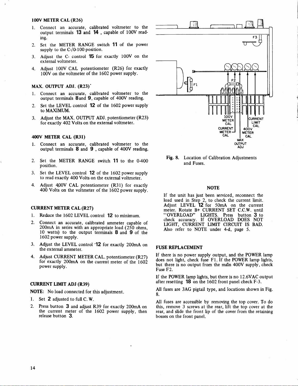
Fig.
8.
Location of
and Fuses.
the
If
load
Adjust LEVEL
MCtEr. ROtAtE
"OVERLOAD"
check accuracy. If OVERLOAD DOES
LIGHT,
Also
FUSE
REPLACEMENT
there
If
does
but
Fuse
If the POWER
after
All
8.
All
this, remove
rear, and
bosses on the
is
not light,
there
F2.
resetting
fuses
fuses
has
unit
used
in Step 2, to check
CURRENT LIMIT CIRCUIT IS
refer
to
power
no
check
no output from the
is
lamp
on
18
are 3AG
are accessible
slide the
pigtail
3 screws at the
front
front panel.
Calibration Adjustments
NOTE
just
12
B+
LIGHTS.
NOTE under 4d,
supply
fuse Fl. If
lights,
the 1602
serviced, reconnect
been
for 50mA on
CURRENT SET C.C.W. UNtiI
output, and the
but
type, and locations shown in
removing the
by
of
lip
the
Press
the
main
there
is
panel
front
rear,
lift the top
the cover
POWER lamp lights,
LIMIT
CAL
I
400v
MAX
OUTPUT
ADJ
the
current
page
400V supply,
no
from
limit.
the current
button 3
NOT
BAD.
5.
POWER lamp
I2.6VAC
F-3.
check
top cover. To do
cover at
the retaining
l
to
check
output
Fig.
the
I4
Page 15

+
1.
Refer to
for adjustments
2. If
the
your
with
Enclose
to, or
service
your
If
your
list
local
distributor
WARRANTY
the
MAINTENANCE
that
may
above-mentioned
unit, pack
letter
a
ship
agency
of
describing
PREPAID ([IPS
(see
authorized
procedures
it
securely (preferably
list
enclosed
B & K-Precision
for
the
SERVICE
section
be applicable
problem
the
preferred)
with
of
your
name
INSTRUCTIONS
your
of
do not
correct the
in the
and include
to the neaiest
unit).
service
nearest
B & K-Precision
problem
origihal
four
carton or
name
B & K-Precision
agencies
seivice
has
agency,
you
been
or
and
write-to:
instruction
manual
are experiencing
doubli-packed)l
address.
Deliver
authorized
misplaced,
contact
DYNASCAN
product,
for a
parts
department, accompanied
enclosed
chicago,
result
removed.
damages
damages,
to state.
and
period
DYNASCAN
upon
To obtain warranty
warranty
Illinois
Exclusions:
of unauthorized
DYNASCAN
resulting
so
This
warranty gives
CORPORATION
the component
year
sf
one
will,
delivery
the
without
to
registration
60635
within
This
warranty
shall
from
above
limitation
loss
from
alterations
not
B & K-Precision
DYNASCAN
6460
Chicago,
LIMITED
warrants
parts
thereof,
the date
charge,
an authorized
proof
by
coverage,
you
card
fifteen
does not
be
liable
of
use. Some
or
specific
of
the date
this
to
(15
or repairs.
exclusion
rights
Service
Deprtment
Product
CORPORATION
West
Cortland
Illinois
ONE.YEAR
to the
will
purchase.
of
repair
B
product
DYNASCAN,
days)
apply
for
be
or
replace,
& K-PRECISION
purchase
of
must be registered
from
in
the event
It
is void
any
consequential
states
do
not
may
not
you
and
Group
Street
60635
WARRANTY
purchaser
original
free irom
B & K-PRECISION,
the date of
apply to
may
defects
at its
option
service
in
of misuse
if
the serial
allow limitati,on
also have
defective
contractor
the form
by completing
purchase.
damages,
you.
other rights
in
of
or abuse
number
of
that its
workmanship
a sales receipt.
646b West
including
B
product
-or
the factory
of
the
is alterid.
without
incidental
which vary
& K-PRECISION
and
materials
or component
iervice
and mailing
Cortland
product
or
consequential
the
Slreet.
or as
defaced or
limitation
from
state
a
your
For
authorized
cannot
be
Cortland
Street,
convenience
to
make
obtained
Chicago,
we
or
Illinois
suggest
can
60635,
repairs
locally, please
refer
send
you
contact
you
the
unit to
properly
your
B
to
the
B & K-PRECISION
packaged
& K-PRECISION
nearest service
to
avoid
contractor.
Service
damage
in
distributor,
Department,
shipment.
who
If wairanty
may
be
,"rui".
6460 west
Page 16

-\
480.152-9-001G
West
6460
Chicogo,
o1980
DYNASCAN
COFlPOF|ATION
Gorflond
lllinois 60635
o
DYNASCAN
Street
CORP.
PRINTED
IN U.S.A.
 Loading...