

Page 1

INSTRUCTION MANUAL
FOR
B & K-PRECISION
MODEL 1601
SOLID STATE
REGULATED DC POWER
SUPPLY
DYNASCAN
CORPORATION
6460 West
Cortland
Street
Chicago, Illinois 60635
Page 2

CONTENTS
Page
SPECIFICATIONS
. . . . . . . .. . . . . . . . . . . . . . . . . . . . . . . . . . . . . . . . . . . . . . . . . . .
3
FEATURES . . . .. . . . . . . . . . . . . . . . . . . . . . . . . . . . . . . . . . . . . . . . . . . . . . . . . . . . .
.
3
INTRODUCTION
.....................................................
4
CONTROLS AND INDICATORS
........................................
4
OPERATING INSTRUCTIONS
.........................................
5
APPLICATIONS
.....................................................
6
General
. . . . . . . . . . . . . . . . . . . . . . . . . . . . . . . . . . . . . . . . . . . . . . . . . . . . . . .
6
Electronic Servicing
. . . . . . . . . . . . . . . . . . . . . . . . . . . . . . . . . . . . . . . . . . . . . .
6
Servicing Battery Operated Equipment
.........................
6
Servicing Vehicular Electronics Equipment
.....................
7
Servicing Plug-In Modules.................................... 9
Using Two Power Supplies For Two Output Voltages............9
Two Power Supplies In Series For O-100 Volt Output . . . . . . . . . . . . 9
Using The Power Supply As A Battery Charger
. . .
. . . . . . ... ........... 10
Other Servicing Applications
.................................
10
Electronics Manufacturing
........................................
10
Electronics Design Engineering
.
....................................
11
Electronics Education
............................................
11
CIRCUIT DESCRIPTION
. . . . . . . . . . . . . . . . . . . . . . . . . . . . . . . . . . . . . . . . . . . . . .
12
MAINTENANCE
. . . . . . . . . . . . . . . . . . . . . . . . . . .
. . . . . . ..*.................
14
Page 3
OUTPUT VOLTAGE
OUTPUT CURRENT
CUMNF&~
LOAD REGULATION
FULLY SOLID STATE
CURRENT LIMITING/
OVERLOAD
PROTECTION
SIMPLIFIED
ZZll&TING
(0-50 VDC
0-2
AMPS
DUAL
METERS
SPECIFICATIONS
O-SO VDC, continuously
var-
iable. Two ranges,
0-25
and
O-50 VDC.
O-2 amperes. Four ranges:
O-SO
mA, 0-0.2A. 0-0.5A,
and
0-2A.
5% to 100% of each current
range.
Maximum 0.1%. typical
0.07%.
LINE REGULATION
RIPPLE
CURRENT DERATING
SIZE
NET WEIGHT
FEATURES
Uses integrated circuits, silicon transistors and diodes,
and an SCR. All the advan-
tages of solid state construction are utilized, including:
Dependability-reliability
No warm up time or stab-
ilization delay
Ruggedness
Compact size
Protects load and instrument
against overload.
Curr
ent
limit is fully adjustable from
approximately 2.5 mA to 2
A. The power supply automatically shuts down and
the OVERLOAD lamp lights
if the preset current limit is
exceeded. After clearing the
cause of the overload, simply push the set/reset button
to restore normal operation.
Permits setting current limit
without disturbing external
load connections or output
voltage settings: does not
re-
quire
application of short
circuit to output terminals.
Simply
push the set/reset
button and adjust the
current limit while reading the
setting on the current meter.
Continuously adjustable over
entire range with a single
control; no range switching
required.
Divided into four ranges.
Fully regulated output at all
current levels.
Allows output voltage and
current to be monitored simultaneously without
switch-
ing
ranges from current to
voltage. Both meters have
overload protection to pre-
vent damage from incorrect
range selection.
FOUR CURRENT
METER RANGES
TWO VOLTMETER
RANGES
STANDBY-DC
ON SWITCH
ON-OFF CONTROL
PILOT LAMP
MECHANICAL
PREREGULATOR
FLOATING OUTPUT
REVERSE POLARITY
PROTECTION
BINDING POSTS
ATTRACTIVE
APPEARANCE
EASY TO OPERATE
Maximum 0.1%. 0.02%
typ-
ical, at output Voltage of
50
VDC and output current of 2
amps
from
105-125
VAC.
5
millivolts peak-to-peak
maximum.
.02 A/°C
above
25°
C am-
bient. (2 A Range only).
14 1/8"
x
3 7/8"
x 10” deep.
11 lbs.
Provides maximum meter
resolution. Selection of meter range also selects coarse
current limit setting.
0-25V and
0-5OV
ranges pro-
vide maximum meter resolution. A mechanical stop
prevents the voltage level
control from exceeding
ap-
proximately 25 volts when
the O-25 V range is selected.
Standby mode disconnects
power
supply from load
without disturbing voltage
or current control settings.
On-off switch is combined
with voltage level control to
assure voltage setting of
zero when unit is turned on.
Lights to indicate at a glance
that the unit is turned on.
Power supply’s rectifier input voltage increases in progressive steps as output
voltage setting is increased.
Improves efficiency; less
power is converted to heat
at low voltage operation.
Permits referencing the positive or negative output to
any external dc potential or
ground.
Protects against accidental
damage from reverse polarity connection to external
power source.
Heavy duty
5-way
binding
posts for positive cmd
negative polarity output and earth
ground.
Modem, functional design.
When more
than
one unit
is
used, units may be stacked.
All controls are
identified
and easy to read. Simplified
operation helps prevent op
erator
mistakes that might
damage equipment.
3
Page 4
INTRODUCTION
The B & K Precision Model 1601 Regulated DC
Power Supply is a versatile, laboratory quality instrument which provides regulated dc voltage and
current outputs of 0 to 50 volts and 0 to 2 amperes
respectively. Its high specifications, operating ease,
and special features make it an excellent choice
for most applications requiring a dc power source.
It is especially well suited for powering transistorized and fully solid state electronic equipment
such as automobile radios and sound systems, battery operated radio receivers, portable radios,
mobile citizen’s band transceivers and Walkie-Talkie
transceivers.
The following list is ‘but a small sample of the
most popular applications for the instrument:
-Service Technicians
-Factory Technicians
-Engineers and
Laboratory
Technicians
-Electronics
Instructors
and Students
CONTROLS AND INDICATORS
Powering equipment or individual circuits during testing
and trouble-shooting in the
service shop.
Powering complete
equipments or individual assemblies during testing in the
factory.
Powering prototype and experimental circuits and
equipments.
Laboratory exercises in basic
and
advanced electronics.
3
2
1
13
12
11
io
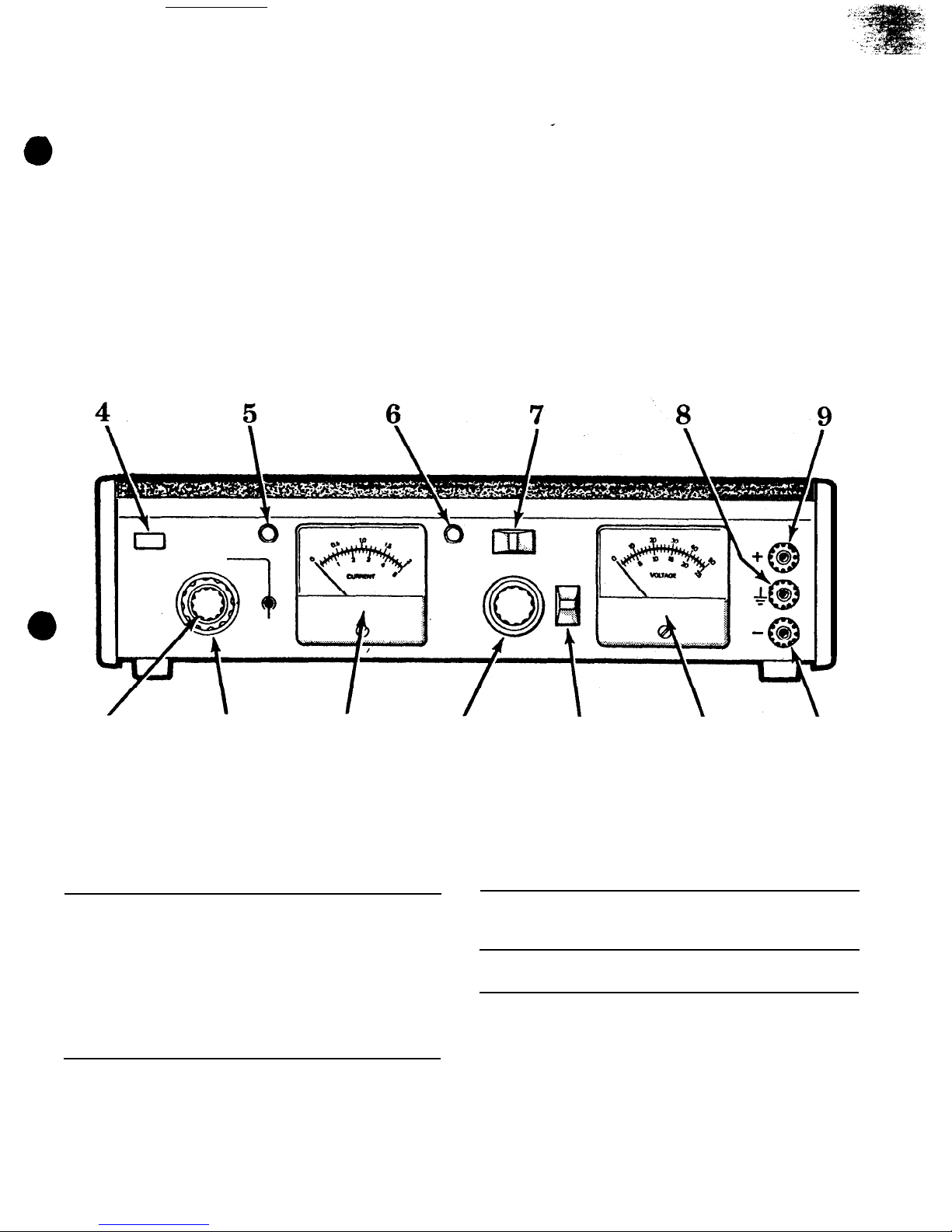
Controls and Indicators
1 current meter
Measures actual output load
4 Push to set
current during normal oper-
CURRENT
ation.
LIMIT or to reset
Indicates current limit value
OVERLOAD
when set/reset button 4 is
button (set/
pushed. reset button)
2 CURRENT
Selects range for current
RANGE switch
meter 1 and coarse setting
of current limit. Full scale
meter
reading
and maxi-
mum current limit of:
0.05A
position
0.2A
position
0.05 ampere
(50
milliamps)
0.5A
position
0.2 ampere
(200
milliamps)
2A position
0.5 ampere
(500
milliamps)
2 amperes
5 OVERLOAD
indicator
(red)
6 POWER indicator Lights continuously while
power supply is turned on.
7 STBY-DCON
switch;
STBY position
l
3 SETCURRENT
LIMIT control
Fine adjustment of current
limit setting. Continuously
adjustable from 5% to 100%
of range which is selected
by CURRENT RANGE switch
2
DC ON position
4
When fully depressed and
held, connects current meter
1
to read the current limit
setting. When pressed and
released, resets overload circuit if it has been tripped.
Lights when current limit has
been exceeded and power
supply output has shut down.
Removes power from output
terminals 9 and 10 and
voltmeter
11 but leaves
power supply activated in a
standby condition.
Applies power to output ter-
minals 9 and
10
and
voltmeter
11
Page 5
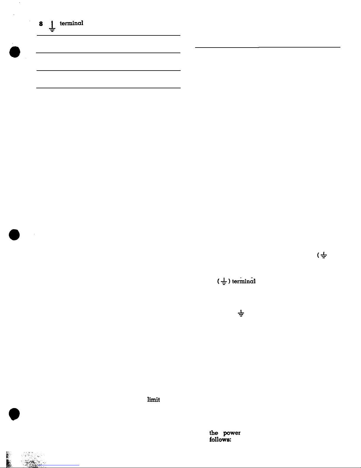
*
c
termina1
Earth and chassis ground
terminal.
9 + terminal
Positive polarity Output terminal.
10
-
terminal
Negative polarity output
terminal.
11
voltmeter
Indicates power supply output voltage.
12
1.
2.
3.
4.
METER
RANGE
switch
0-5OV
position
Selects full scale range of
50 volts for voltmeter 11
0-25V
position
Selects full scale range of
25 volts for voltmeter
11
OPERATING INSTRUCTIONS
a.
b.
C.
d.
13 LEVEL control
Turn off the power supply before plugging it
into an ac outlet. Turn off by
rotating
the LEVEL
control
13 fully counterclockwise until it
“clicks” off.
Connect the power cord to a 105-125 volt 60 Hz
ac outlet.
WARNING
Use only a polarized
3-wire
outlet. This
assures that the power supply chassis is
connected to a good earth ground and prevents danger from electrical shock. If a
2-wire
to
3-wire
adapter must be used, be
sure the ground wire of the adapter is
attached to a good earth ground.
Turn on the power supply by rotating the
LEVEL control 13 slightly clockwise past the
“click”. The POWER indicator 6 will light.
Determine the maximum safe load current for
the device to be powered and set the current
limit for that value as follows:
Set the coarse current limit with the CUR-
RENT RANGE switch 2 . When possible,
select a range that provides the desired current liiit at a value above 20% of the full
scale
reading.
7
.
Return the “STBYDC ON” switch 7 to the
DC ON position and set the output voltage as
follows:
Push and hold the set/reset button 4 while
making
fine
current limit adjustment with
the SET CURRENT
LIMIT
control 3 for the
desired current limit as read on the current
meter
1 .
a.
Release the set/reset button 4 .
b.
If the maximum safe load current is
un-
known,
start with a low current
lit
setting.
If the setting is too low, the overload circuit
will merely trip when power is applied to
the
load in steps 7 and 8. If so, increase the
current limit setting in small steps until the
overload circuit does not trip during normal
operation.
8. If the load current exceeds the current limit, the
OVERLOAD lamp 5 will light and the power
supply will shut down
.(the
current meter 1
and voltmeter 11 will drop to zero). Restore
;~Iowyw=r supply
to normal operation as
.
.
and prevents LEVEL control
13 from increasing the
voltage above approximately
25 volts.
Turns off power supply at
extreme counterclockwise ro-
tation. Clockwise rotation
turns on power supply and
adjusts output voltage (volt-
age output level is not
changed by the METER
RANGE switch 12 ). Also,
prevents METER RANGE
switch from being set to O-25
V position when LEVEL control is advanced beyond
ap-
proximately 25 volt output.
5.
6.
Set the “STBY-DC ON’ switch 7 to the STBY
position
while
connecting the test leads.
Connect the power supply output to the device
being powered with test leads as follows:
a.
b.
C.
Connect the positive polarity input of the
device being powered to the (+) terminal
9 of the power supply.
Connect the negative polarity input of the
device being powered to the
(-)
terminal
10 of the power supply.
If the positive polarity of the device beiig
powered is also to be ground reference,
jumper the (+) terminal 9 to the
(+ )
ter-
minal 8
.
If the negative polarity of the
device being powered is to be ground reference, jumper the
(-)
terminal 10 to the
(hlterminal
8
.
If neither the positive nor
negative polarity of the device bemg pow-
ered is to be grounded, but the chassis of
the device needs grounding, connect a separate test lead from the chassis of the device
to the ( * 1 terminal8of the power supply.
Set the METER RANGE
switch
12 to the
0-25V
position if the output voltage is to be
set for 25 volts or
less,
or to the
0-50V
position if the output voltage is to be sat for
more than 25 volts.
Turn LEVEL control 13 clockwise until the
desired output voltage is read on the volt-
meter 11 .
5
Page 6

a.
b.
To reset the power supply, press and release
the
set/reset
button 4 . If the overload
condition was intermittent, this action will
restore operation.
If the OVERLOAD lamp 5 remains lighted,
use one of the three following
techniques
before resetting the power supply again:
-Reduce the load current.
-Reduce the voltage slightly with the
LEVEL control 13
.
-Increase the current limit slightly with the
SET CURRENT LIMIT control 3
.
If the
normal load current is unknown, this technique may be used; but, if the current limit
was already set for the maximum safe
load current, do not increase the current
limit further.
NOTE:
input which results in a surge current
when power is intially applied. When
powering such equipment, the overload
may activate when the STBY-DC ON switch
is placed in the DC ON position with full
operating voltage previously set. If this
occurs, reduce the voltage setting and
bring it up gradually to allow the capaci-
tors in the equipment to charge; this eliminates the surge current.
c. If the power supply continues to shut
down
at the correct current limit value, check the
LOAD current to determine the reason for
the overload.
9. To remove power from the load without dii
turbing the voltage or current limiting settings,
merely set the “STBY-DC ON” switch 7 in the
Some equipment has a highly capacitive
STBY position.
APPLICATIONS
GENERAL
This instrument may be used to power a vast
assortment of items in the fields of electronics servicing, electronics manufacturing, electronics design
engineering and electronics education. The power
suply output is fully adjustable from
0
to 50 volts,
and 0 to 2 amperes. This flexibility makes it suitable
for most applications requiring a dc power source.
ELECTRONICS SERVICING
The electronics technician uses the power supply
as
the power source for much dc and battery
powered equipment being tested and serviced. It
may also be used as the power source for testing
modules or circuits that are removed from the equip
ment where it normally receives its power.
SERVICING BATTERY OPERATED EQUIPMENT
Most equipment which operates from internal batteries can be tested and serviced using this power
supply as its power source. The excellent filtering
characteristics makes the power supply a suitable
substitute for batteries, with the added
advantage
that the effects of
varying
the voltage can be
checked. The following items are among the more
6
POKER SUPPLY
common types that may be powered from this
power supply:
Portable
AM or AM/FM radio receivers
Portable short wave and multi-band radio receivers
Portable paging receivers
Portable monitor receivers
Walkie
Talkie type transceivers
Portable two-way communications transceivers
Portable cassette recorders and players
Portable calculators
Other battery operated electrical or electronic
devices
CAUTION
Observe correct polarity. Some equipment
may not contain reverse polarity protec-
tion, and may be damaged if polarities are
reversed.
When servicing this type of equipment, remove
the batteries and connect test leads from the
(+)
and
(-)
terminals of the power supply to the
(+)
and (-)
power input points of the equipment being serviced
as shown in Figure 1. The earth ground terminal of
EQUIPMENT
BEING SERVICED
t
CURRENT LIMIT
Set VOLTAGE to the
to maximum
input
terminal voltage
value
of
fully
charged batteries.
Figure 1. Typical Power Supply Connections to
Battery Operated Equipment
COMPARTMENT
Page 7

the power supply is not normally used nor required
in this application.
Using separate test lead colors,
such
as red and black, reduces the chance of acci-
dental
reverse polarity connection. Set the current
limit to the maximum input current specification of
the equipment being serviced. If this figure is unkn
o
wn, start with a low current limit and increase
the setting in small increments until the overload
circuit in the power supply does not trip when power
is applied to the unit under test. Set the voltage to
the same value that would be present if a full set of
fully charged batteries were installed. Flashlight
cells of all sizes are rated at 1.5 volts ‘each. Other
batteries normally state the voltage on the label,
and
the required operating voltage for the equip
ment being serviced is often stated on a label in
the equipment. For units using more than one bat-
tery, check whether the batteries are connected in
series or parallel. For the parallel connected arrangement, set the power supply voltage to that of
a single cell; a higher voltage may damage the
equipment. For the series connected arrangement,
add the voltages of all cells and set the power sup
ply voltage to that sum.
A simplified method of making connections to the
power input points of battery operated equipment
may be to use a “dummy” battery. A dummy bat-
tery sits in the battery compartment and makes
good electrical contacts with the power input points,
but has readily accessible terminals or test leads
for interconnection to the power supply. The body
of the dummy battery may be made from wood or
other nonconductive material. The end caps must
be good electrical conductors which are connected
to terminals or test leads. The unit must fig snugly
in the battery compartment to assure good electrical
contact. An improved version may include a spring
to insure a snug fit.
SERVICING VEHICULAR
ELECTRONICS EQUIPMENT
When servicing electronics equipment for auto.
mobiles. trucks, and other vehicles, the equipment
is normally removed from the vehicle for bench
testing.
This power supply is an excellent dc power
source for bench testing such equipment. The
fol-
lowing items are among the more common types of
vehicular electronics equipment that may be
powered from this power supply:
POWER
SUPPLY
AM, AM/FM and AM/FM/Stereo automobile
receivers
*Tape players
Citizen’s band transceivers
Monitor receivers
Automobile amateur radio receivers
*Some aircraft equipment
*Some ship-to-shore and ship-to-ship marine band
transceivers
*Some vehicular two-way communications trans-
ceivers
*Some automotive amateur radio transceivers
‘Maximum current 2 amperes unless special procedures are
used as described in this section of the
manual.
Most automobiles and other vehicles use
12-volt
electrical systems. Although the electrical system is
normally referred to as a
12-volt
system, actual bat-
tery voltage when fully charged is approximately
14 volts. The power supply may be set
at
14 volts
for servicing equipment from vehicles with
12-volt
electrical systems.
Some trucks use a 24-volt
elec-
trical
system; bench testing of equipment from these
systems should be performed at 28 volts. Aircraft
normally use a 28-volt electrical system, and a
bench test voltaqe of 32 volts is used.
Practically all vehicles use a negative ground
electrical system, althouqh a positive ground system
is occasionally found. Electronic equipment which
is built for use only in negative ground vehicles
usually has its chassis common with the negative
polarity of input power. In some cases, there is no
separate negative polarity power cable, since the
chassis
becomes
grounded
when the equipment is
installed in the vehicle. Some equipment is built for
use in either neqative or positive ground electrical
systems, in which case the chassis may be isolated
from both the positive and ‘negative input polarities.
There is virtually no equipment built for positive
ground electrical systems only, although some elec-
tronics equipment may use its ungrounded positive
polarity as reference for circuit operation.
CAUTION
Carefully observe polarity of connections.
Equipment may be damaged if polarities
are reversed.
When servicing this type of equipment, the
(+)
and
(-)
terminals of the power supply should be
connected to the
(+)
and
(-)
power input points of
the equipment being serviced with test leads.
Fig-
EQUIPMENT BEING
SERVICED
to
maximum
input
current
specifi-
cation of
eguipme
being
serviced
+5
Figure 2. Typical Power Supply Connections to Vehicular Equipment
(Negative Ground System, Grounded Chassis Shown]
7
Page 8

ure 2 shows a typical example. The power supply
offers overload protection; therefore, any fuse in the
equipment’s power cable is not required during
testing. In fact, a convenient connection point may
be to the fuseholder. Normally, the equipment chassis should be grounded. Usually, the negative po-
larity of the equipment is common with the chassis
and a jumper may be connected between the
(* )
and
(-)
terminals of the power supply.
In those cases where the chassis is not common
with the negative polarity, connect a separate test
lead free from the
(
-h- )
terminal of the power supply
to the chassis of the equipment being serviced.
Figure 3 shows the proper interconnection between
the power supply and the equipment under test for
all possible situations.
8
POWER
SUPPLY
EQUIPMENT
BEING
POWERED
EQUPMENT
POWER
BEING
SUPPLY
POWERED
-F'
If there is any doubt that the chassis
may not be
common with the negative polarity, use a seground connection from the
(*l
terminal
equipment chassis. No damage can result
technique is used.
Set the power supply voltage to the specification
voltage for the equipment being serviced
(normally
the voltage value of a fully charged vehicle
battery).
Set the current limit to the maximum input
current
specification plus 5%.
If specification information
is unavailable, start with a moderate current
limit
and find the overload threshold. Increase the
cur-
rent limit 5% above threshold to prevent
overload
turn-off during testing.
Note that most solid
state
receivers have a much higher load current
with
strong audio output. Therefore, the threshold
should
EQUIPMENT
POWER
BEING
POWERED
POWER
EQUIPMENT
BEING
SUPPLY
Figure 3. Power Supply Interconnect Possibilities
POWER SUPPLY
#l
f
RECOMMENDED ONLY FOR
POWER SUPPLY
#2
Figure 4. TWO Power Supplies Connected in Parallel for 4 Amp Output
Page 9

be determined with audio output: otherwise, the
overload circuit will be activated upon reception of
audio.
Some of the vehicular equipment listed may re-
quire more than 2 amperes of load current. This is
especially true
of transceivers during the transmitting mode and some tape players in the track
change
mode. If you have only occasional need to
service
such equipment, another power supply is
not
necessarily required.
A vehicular battery of the
correct voltage and of sufficient capacity will suffice.
During
testing, the transmitter does not normally
need to be keyed except for short periods. The battery will provide adequate power for such testing.
The power supply can be used as a battery charger
to restore the battery to full charge, and all non-
transmit testing can be done using the power supply
as the dc power source.
Refer to Figure 4. Although it is Possible to obtain
up to 4 amperes load current from two power sup
POWER SUPPLY
MODULE BEING
SERVICED
Set CURRENT LIMIT
to
specification
for module being
serviced.
Figure 5.
Typical Power Supply
quired for bench testing modules. Figure 5 shows a
typical test set-up. Connect the
(+)
and
(-)
outputs
of the power supply to the (+) and
(-)
power terminals of the module. Identical power is sometimes
required at two or more terminals of a module. If
so, jumper together these terminals. An earth
ground may or may not be required. A test hook-up
diagram for
bench
testing the module should be
obtained. It should specify the operating voltage
and current limit. The current limit will typically be
lower than those previously described for battery
operated and vehicular equipment, since only a
single module is being powered.
Module testing is more likely to require two separate dc voltages simultaneously. Refer to the next
paragraph for information.
USING TWO POWER SUPPLIES
FOR TWO OUTPUT VOLTAGES
When two separate dc voltages are
required
Set VOLTAGE to
specification for
module being serviced.
plies connected in parallel, it is not recommended
except for use by highly experienced personnel.
The power supplies should not be connected directly
in parallel, but should be isolated by very low resistance so that balance is not so critical. Even with
this technique, the power supplies must be well
balanced or the unit carrying the heavier load will
overload and turn off, which, in turn, will cause the
other Power supply to overload and turn off. It is
very difficult to bring the power supply output of
both units up to operating voltage without disturbing the balance. One method to achieve balance is
to use an external switching arrangement which
allows selection of the load or a dummy load. The
dummy
load should be selected to draw approx-
imately 1
ampere at the operating voltage of the
main load:
½
ampere from each power supply. The
Power
supplies
can be accurately balanced into the
dummy
load without fear of overload, then switched
to the main load.
SERVICING PLUG-IN MODULES
Equipment containing plug-in modules is often
repaired
by replacing a malfunctioning module.
then servicing the defective module on the bench.
A dc Power source such as this power supply is
re-
Connection to Module For Bench Testing
simultaneously for testing equipment, two power
supplies may be used. Set the voltage and current
limit for each power supply independently as required by each circuit.
Only the circuit reference
point must be common between the two supplies.
Figure 6 shows some typical examples of proper
power supply connections when using two units.
Take extra precaution to prevent reverse polarity
connections in’ such situations. The numerous connections can become confusing. Additional colors
for the test leads will be helpful. The power sup
plies are protected from reverse polarity damage
from an external voltage source (such as the other
power supply).
TWO POWER SUPPLIES IN SERIES
FOR O-100 VOLT OUTPUT
The power supplies may be connected in series
for output voltages over 50 volts at 0 to 2 amperes.
Figure 7 shows the correct connections. Set the
current limit for both supplies at the same value and
equalize the voltage between the two units. Since
both units are connected in series, an overload in
either unit will shut down the output from both
sup-
plies, The power supplies are built to permit stacking when two units are used.
9
Page 10

EQUIPMENT
BEING
POWERED
NO. 2 (3
V)
POWER
NO. 2
POWER
NO. 2
POWER
NO. 1
POWER
NO. 2
SUPPLY
(15 V)
SUPPLY
(10 V)
Figure 6. Using Two Power Supplies for Two Output Voltages (Typical Examples1
USING
THE POWER SUPPLY
AS A BATTERY CHARGER
The power supply can be used as a battery
charger to restore the charge in rechargeable batteries such as lead-acid, nickel-cadmium and some
alkaline types. Refer to the battery manufacturer’s
charging specifications for proper voltage and current settings. Charging information is often printed
on the batteries. For batteries that specify maximum
charge currents of less than 2 amperes, set the current limit to the specified value. For batteries with
higher charge current capacities, set the current
limit to maximum. The charging current of a bat-
tery is highest when the charger (power supply) is
initially connected.
As a result, current overload
can occur before voltage is brought up to specified
charging voltage. If this happens, reduce the power
supply voltage slightly so the power supply does
not shut down. After a period of time, increase the
voltage until the full charge value can be obtained
without shutdown.
OTHER SERVICING APPLICATIONS
The instrument can be used as
a bias supply to
test the effects of varying the dc bias, such as the
AGC bias in a television receiver. Typically, the
equipment being tested contains its own power sup
ply and operates from ac power. DC voltages are
present in the circuits.
The power supply is floated
from an appropriate point in the circuit, such as the
emitter of a transistor. The power supply output is
then
applied
to another point, such as the base of
that transistor. Varying the power supply voltage
then varies the dc bias on that stage,
and
the effects
POWER SUPPLY
#l
POWER
SUPPLY #2
Figure 7. Two Power Supplies in Series
for Cl-100 Volt Output
may be noted.
A series limiting resistor is often
used to protect circuits from overdissipation.
ELECTRONICS MANUFACTURING
In electronics manufacturing, the power supply is
most often used as a dc power source to test
completed units for proper operation and compliance with specifications.
The
instrument could also
be used in incoming inspection to test purchased
equipments or subassemblies. The use of the power
supply for testing complete units is very similar to
that previously described for servicing battery op
Page 11

erated
and vehicular equipment, while its use for
testing subassemblies is very similar to that described for servicing modules.
This power supply is particularly well suited for
manufacturing. applications because of its ease of
operation and the speed at which it will accomplish
its
job, in
addition to its other features. When load
current or total power dissipation are among the
main characteristics to be measured, the total load
current
and
voltage are instantly displayed on the
two meters.
The current limit can be adjusted so
that all units which do not meet the load current
specification will cause the overload to trip, and
the unit can be rejected.
ELECTRONICS
DESIGN ENGINEERING
The technician or engineer working in an
engi-
neering laboratory requires a power supply to
power prototype and experimental circuits. This
power supply is ideal because it monitors both current and voltage simultaneously, limits current to
protect the circuit, is adjustable over such a wide
range, and has excellent regulation and very low
ripple.
Use of the instrument in an engineering laboratory
is very similar to that previously described for servicing electronics equipment and modules, except
that lower currents may be prevalent when powering single stage experimental circuits. The current
limiting feature is very valuable in this application
because it protects the unproven circuit from
damage.
ELECTRONICS EDUCATION
The student in an electronics school may use the
power supply for powering equipment and circuits
as previously described for all other applications.
In addition, the power supply will be used in the
laboratory classroom to conduct experiments in fundamental electronics. In learning
Ohm's
law, for
example, the relationships of resistance, current and
voltage are vividly demonstrated by the use of the
power supply. Being able to observe both the current and voltage meters simultaneously is a great
aid in such experiments. Figure 8 shows typical
examples of the types of experiments and exercises
that may be conducted.
!
POWER SUPPLY
OBSERVE
OHMS
LAW
BASIC VOLTAGE DIVIDER
R1
BASIC CURRENT DIVIDER
*xa
x1+12'11N
POWER SUPPLY
SERVE
STIC
OF DIODE
MEASURE VDI &
I
VARY
EIN
CHARACTERISTIC
OF
ZENER
DIODE
xi--~$~;:-~I
Rl
Figure
8.
Typical Laboratory Classroom Experiments Using The Power Supply
11
Page 12

CIRCUU
IT DESCRIPTION
GENERAL
The power supply converts a 117 VAC input to a
highly regulated and filtered dc output that is fully
adjustable from 0 to 50 volts and 0 to 2 amperes.
The circuits that accomplish this action may be
divided into five main groups as follows:
-Unregulated B+ Source. Converts the ac input
into a raw, unregulated dc voltage.
_V+
and V- Source.
Converts the ac input to
+15
VDC (V+) and -15 VDC
(V-)
for powering
active elements ICI and IC2 in the control circuits
and control sensing circuits group.
-Control Circuits.
Controls the unregulated B+
source to provide a highly regulated B+ output
that is adjustable from 0 to 50 volts.
-Current
Sensing Circuits. Establishes the current
limit, senses the load current, and activates
an
overload detector that shuts down the power
supply if the current limit is exceeded.
-Metering. Monitors the output voltage and
current.
Refer to Figure 9, the functional diagram, and to
the schematic diagram. Circuit descriptions make
constant reference to these diagrams.
NOTE
The voltages in the following circuit descriptions, and on the diagrams, are measured with respect to the regulated B+
output (the + terminal). Note that this
point is floating independent of the chassis
of the power supply.
UNREGULATED B+ SOURCE
The unregulated B+ source circuit converts the
117 volt ac input to a raw, unregulated B+ output.
Later,
in the control circuits, the unregulated B+ is
converted into the regulated B+ output of the power
supply.
The unregulated B+ output level is
pre-regulated
in coarse steps. As the LEVEL control is rotated
clockwise from zero to maximum, the unregulated
B+ voltage changes from its lowest to its
highest
value in four steps.
This minimizes the
difference
between the unregulated B+ and the regulated B+
output, which always keeps power dissipation
with-
in safe limits.
The main components which make up
this circuit
are power transformer
Tl,
pre-regulator switch
as-
sembly S5, bridge rectifier
BRl,
and filter capacitor
C8.
The ac input is applied to the unregulated
B+
circuit through on-off switch S4 (which is
part
of the
LEVEL control), across neon POWER lamp
NE1
(which glows continuously as a pilot lamp to
show
that power is on), to power transformer
Tl.
Power
transformer
Tl
has four taps in its
main
power output winding. At the lowest voltage setting, only the
low voltage portion of the
transformer
is connected
into the rectifier (this is the condition shown on the
schematic diagram). As the LEVEL control is rotated
clockwise, cams operate microswitches
S5-C,
then
S5-B,
and finally
S5-A.
Each cam-operated
microswitch selects another tap on the secondary of the
power transformer and sequentially steps the rectifier input voltage to a higher value.
Bridge rectifier BRl converts the ac power to full
wave dc, which is filtered by C8. The unregulated
B+ output at C8 is regulated and filtered by the
control circuits.
V+ AND V- SOURCE
The V+ and V- source is a completely separate
power source for powering comparator
IC1.
and
voltage reference and error amplifier
IC2.
These
circuits must be free from the extreme voltage
var-
iations found in the other power source circuits.
Figure 9. Power Supply Functional Diagram
12
Page 13

The control Power winding of
Tl.
diodes D9 and
DlO,
and filter capacitors Cl0 and
C11
form the
V+
and V- voltage source. These power source Circuits provide
+
15 and -15 volts respectively. Both
the
V+
and
V-
voltages float with respect to the
regulated output, and are also independent of the
variable unregulated B+ voltage.
CONTROL CIRCUITS
The control circuits convert the unregulated B+
voltage
into
the regulated B+ voltage. The control
circuits establish the reguiated B+ level in
response
to the
setting
of LEVEL control R27. When R27 is
set for
O
volts, the following circuit conditions
exist:
__Voltage
reference IC2 provides a stable +7 V
reference at
IC2-6.
_The +7 V reference is divided across R13 and
Rl4 to
place
+3.5
V on the inverting input (pin
4)
of
error amplifier IC2.
_The regulated B- output voltage is
0
V.
_The
+7
V reference is divided across current
path
I,.
which consists of
R15,
R27 (Approximately 0 ohms at this time), R37 and R34. This
places approximately
+3.5
volts on the
non-
inverting input (pin 5) of error amplifier IC2.
__Since
the inverting and non-inverting inputs
to
IC2
are equal, no output is developed at
IC2-9.
_No
drive is applied to series pass regulator
Q1,
Q2 and the output remains at zero volts.
When LEVEL control Fi27 is increased to a higher
voltage level, the following circuit action
occurs:
__The
resistance of R27 is added to the voltage
divider network, decreasing current I,.
__The
voltage at
IC2-5
increased (less drop across
R15), and error amplifier IC2 produces an out-
put which biases regulator
Ql, Q2
into oper-
ation.
__The
regulator allows some of the unregulated
B+
to pass to the output terminals and the out-
put voltage rises.
-As
the output voltage rises, the B- becomes
more negative.
-Current
Jr
increases as B- becomes more nega-
tive,
and the voltage at
IC2-5
decreases until
balance is achieved.
When LEVEL control R27 is decreased, the oppo-
site action occurs. Once
R27
is set and balance is
achieved, any load current changes that tend to
change the
output
voltage are sensed and corrected.
CURRENT SENSING CIRCUITS
The major components in the current sensing cir-
cui
t
s are comparator
IC1.
overload switch
SCRl,
and current sensing resistors R1 thru R4. These
circuits monitor the load current and shut down the
power supply
if the preset current limit is exceeded.
First, let us examine the current sensing resistors
R1
thru R4.
These precision, low value resistors are
in
series with the
output
load current. The values
are
chosen so that the maximum current for a
chosen
range Produces exactly 1 volt drop
across
the
resistor (for example, if the 2A range is
selected
2 amps
through resistor R4 develops exactly
1
volt).
The voltage developed across the current
sensing resistor is applied as the non-inverting input
(pin 2) to comparator ICI.
The inverting input at pin 3 of comparator
ICl
is
a 0 to 1 volt dc potential selected by the SET CURRENT LIMIT control R8.
Whenever the output load current produces a
voltage drop across the selected current sensing
resistor
(R1
thru R4) that is greater than the preset
voltage on the inverting input of
IC1,
a Positive out-
put voltage of approximately 1 volt appears at the
output (pin 7) of comparator
ICl.
This voltage
drives the gate of overload switch
SCR1
and turns
it on. Overload switch
SCRl
grounds pin 10 of error
amplifier IC2, which inhibits its operation regardless
of all other inputs and shuts down the power supply.
SCR1
also provides the ground path which allows
the OVERLOAD lamp to light. Set/reset switch S3
opens the voltage path to SCRI to reset it to an off
condition.
The STBY-DC ON switch
(S6)
is also connected to
pin
10
of error amplifier IC2. In the STBY position,
this switch grounds
IC2-10
and inhibits its operation,’
thus disabling the power supply output.
METERING
Voltmeter Ml is connected directly across the output terminals to measure output voltage. Series
resistors, as selected by METER range switch S2,
calibrate the meter to read 0-25V or 0-5OV. A mechanical interlock prevents the LEVEL control from
being increased above approximately 25 volts when
S2 is in the 0-25V range.
Current meter M2 is actually a voltmeter that is
calibrated to accurately measure output load cur-
rent. The meter measures the voltage that is de
veloped across the current sensing resistor, which
is exactly 1 volt for a full scale meter reading.
When setting the current limit, switch S3 is actuated,
which connects the current meter directly across the
SET CURRENT LIMIT control R8. This control se-
lects a voltage from 0 to
lV,
which very accurately
corresponds to the current limit value read on the
meter.
Page 14

MAINTENANCE AND CALIBRATION
WARNING
-
THE FOLLOWING INSTRUCTIONS ARE FOR USE BY
QUALIFIED PERSONNEL ONLY. TO AVOID ELECTRICAL SHOCK, DO NOT
PERFORM ANY SERVICING OTHER THAN THAT CONTAINED IN THE OPERATING INSTRUCTIONS UNLESS YOU ARE QUALIFIED TO DO SO.
This power supply is built to provide long,
trouble-free service and does not require periodic
maintenance. If the unit malfunctions, use conventional troubleshooting techniques, such as voltage
and resistors checks, to isolate the defective component. If electrical components are replaced, the
unit should be recalibrated.
CALIBRATION
To gain access to the calibration adjustments, re-
move the 3 screws at the rear of the top cover, then
lift the top cover at the rear and slide the front lip
of the cover from the retaining bosses on the front
panel. Refer to Figure
10
for locations of calibration
adjustments.
MAX OUTPUT ADJ
(R24)
1. Connect an accurate, calibrated voltmeter to the
output terminals of the power supply.
2. Set the LEVEL control of the power supply to
maximum.
3. Adjust the MAX OUTPUT ADJ potentiometer
(R24)
for exactly 50.5 volts on the external volt-
meter.
25V CAL
(R33)
Connect an accurate, calibrated voltmeter to the
output terminals of the power supply.
Set the METER RANGE switch of the power supply to the 25V position.
Adjust the LEVEL control of the power supply for
exactly 20 volts on the external voltmeter.
Adjust 25V CAL potentiometer
(R33)
for exactly
20 volts on the voltmeter of the power supply.
50 VOLT
25 VOLT
CURRENT
5OV
CAL
(R30)
1.
2.
3.
4.
Connect an accurate, calibrated voltmeter to the
output terminals of the power supply.
Set the METER RANGE switch of the power
sup-
ply to the
5OV
position,
Adjust the LEVEL control of the power supply for
exactly 50 volts on the external voltmeter.
Adjust
5OV
CAL potentiometer
(R30)
for exactly
50
volts on
the voltmeter of the power supply.
CURRENT
METER CAL (R-29)
1. Connect an accurate, calibrated ammeter capable of 2A in series with an appropriate load
(1 ohm, 4 watts) to the output terminals of the
power supply.
2. Adjust the LEVEL control of the power supply
for exactly 2A on the external ammeter.
3. Adjust CURRENT METER CAL potentiometer
(R29)
for exactly 2A on the current meter of the
power supply.
INTERNAL CURRENT LIMIT ADJ. (R-21)
1. Turn SET CURRENT LIMIT (3) to full C.W.
2. Adjust R-21 to full scale when pressing the set/
reset button (4).
FUSE REPLACEMENT
If these is no power supply output and the
POWER lamp does not light, check fuse
Fl.
The
fuse
Fl
is located inside the cabinet, which is made
accessible by removing the 3 screws at the rear of
the top cover, then lifting the top cover at the rear
to slide the front lip of the cover from the retaining
bosses on the front panel.
Fuse
Fl
is soldered to a terminal strip at the right
of the main power transformer. Figure 10 shows the
location of the fuse.
INTERNAL CURRENT LIMIT ADJ
\
-ERChL
14
Figure
10.
Location of Calibration Adjustments and Fuses
Page 15

Page 16

 Loading...