

Page 1
Series: 2560
4CH/2 CH
Digital Storage Oscilloscopes
Mixed Signal Oscilloscopes
USER MANUAL
Test Equipment Depot - 800.517.8431 - 99 Washington Street Melrose, MA 02176
TestEquipmentDepot.com
Page 2

Safety Summary
The following safety precautions apply to both operating and maintenance personnel and must be
followed during all phases of operation, service, and repair of this instrument.
Before applying power to this instrument:
Read and understand the safety and operational information in this manual.
Apply all the listed safety precautions.
Verify that the voltage selector at the line power cord input is set to the correct line voltage.
Operating the instrument at an incorrect line voltage will void the warranty.
Make all connections to the instrument before applying power.
Do not operate the instrument in ways not specified by this manual or by B&K Precision.
Failure to comply with these precautions or with warnings elsewhere in this manual violates the
safety standards of design, manufacture, and intended use of the instrument. B&K Precision
assumes no liability for a customer’s failure to comply with these requirements.
Category rating
The IEC 61010 standard defines safety category ratings that specify the amount of electrical energy
available and the voltage impulses that may occur on electrical conductors associated with these
category ratings. The category rating is a Roman numeral of I, II, III, or IV. This rating is also
accompanied by a maximum voltage of the circuit to be tested, which defines the voltage impulses
expected and required insulation clearances. These categories are:
Category I (CAT I): Measurement instruments whose measurement inputs are not intended to be
connected to the mains supply. The voltages in the environment are typically derived from a
limited-energy transformer or a battery.
Category II (CAT II): Measurement instruments whose measurement inputs are meant to be
connected to the mains supply at a standard wall outlet or similar sources. Example measurement
environments are portable tools and household appliances.
Category III (CAT III): Measurement instruments whose measurement inputs are meant to be
connected to the mains installation of a building. Examples are measurements inside a building's
circuit breaker panel or the wiring of permanently-installed motors.
Category IV (CAT IV): Measurement instruments whose measurement inputs are meant to be
connected to the primary power entering a building or other outdoor wiring.
Measurement Categories
These digital oscilloscopes can make measurements in measurement category I (CAT I).
Do not exceed a voltage input of more than 5 V absolute value for a 50 Ω impedance input or 400 V
absolute value for a 1 MΩ impedance input.
i
Page 3

This oscilloscope can only be used for measurements within its specified measurement category.
Do not use this instrument in an electrical environment with a higher category rating than what is
specified in this manual for this instrument.
You must ensure that each accessory you use with this instrument has a category rating equal to
or higher than the instrument's category rating to maintain the instrument's category rating.
Failure to do so will lower the category rating of the measuring system.
Electrical Power
This instrument is intended to be powered from a CATEGORY II mains power environment. The
mains power should be 120 V RMS or 240 V RMS. Use only the power cord supplied with the
instrument and ensure it is appropriate for your country of use.
Ground the Instrument
To minimize shock hazard, the instrument chassis and cabinet must be connected to an electrical
safety ground. This instrument is grounded through the ground conductor of the supplied threeconductor AC line power cable. The power cable must be plugged into an approved threeconductor electrical outlet. The power jack and mating plug of the power cable meet IEC safety
standards.
Do not alter or defeat the ground connection. Without the safety ground connection, all accessible
conductive parts (including control knobs) may provide an electric shock. Failure to use a properlygrounded approved outlet and the recommended three-conductor AC line power cable may result
in injury or death.
Unless otherwise stated, a ground connection on the instrument's front or rear panel is for a
reference of potential only and is not to be used as a safety ground.
Do not operate in an explosive or flammable atmosphere.
Do not operate the instrument in the presence of flammable gases or vapors, fumes, or finelydivided particulates.
ii
Page 4
The instrument is designed to be used in office-type indoor environments. Do not operate the
instrument
In the presence of noxious, corrosive, or flammable fumes, gases, vapors, chemicals, or
finely-divided particulates.
In relative humidity conditions outside the instrument's specifications.
In environments where there is a danger of any liquid being spilled on the instrument or
where any liquid can condense on the instrument.
In air temperatures exceeding the specified operating temperatures.
In atmospheric pressures outside the specified altitude limits or where the surrounding gas
is not air.
In environments with restricted cooling air flow, even if the air temperatures are within
specifications.
In direct sunlight.
This instrument is intended to be used in an indoor pollution degree 2 environment. The operating
temperature range is 10 °C to 40 °C and the operating humidity is ≤ 85 % relative humidity at 40 °C,
with no condensation allowed. Measurements made by this instrument may be outside
specifications if the instrument is used in non-office-type environments. Such environments may
include rapid temperature or humidity changes, sunlight, vibration and/or mechanical shocks,
acoustic noise, electrical noise, strong electric fields, or strong magnetic fields.
Do not operate instrument if damaged
If the instrument is damaged, appears to be damaged, or if any liquid, chemical, or other material
gets on or inside the instrument, remove the instrument's power cord, remove the instrument
from service, label it as not to be operated, and return the instrument to B&K Precision for repair.
Notify B&K Precision of the nature of any contamination of the instrument.
Clean the instrument only as instructed
iii
Page 5
Do not clean the instrument, its switches, or its terminals with contact cleaners, abrasives,
lubricants, solvents, acids/bases, or other such chemicals. Clean the instrument only with a clean
dry lint-free cloth or as instructed in this manual.
Not for critical applications.
This instrument is not authorized for use in contact with the human body or for use as a component
in a life-support device or system.
Do not touch live circuits
Instrument covers must not be removed by operating personnel. Component replacement and
internal adjustments must be made by qualified service-trained maintenance personnel who are
aware of the hazards involved when the instrument's covers and shields are removed. Under
certain conditions, even with the power cord removed, dangerous voltages may exist when the
covers are removed. To avoid injuries, always disconnect the power cord from the instrument,
disconnect all other connections (for example, test leads, computer interface cables, etc.),
discharge all circuits, and verify there are no hazardous voltages present on any conductors by
measurements with a properly-operating voltage-sensing device before touching any internal parts.
Verify the voltage-sensing device is working properly before and after making the measurements
by testing with known-operating voltage sources and test for both DC and AC voltages. Do not
attempt any service or adjustment unless another person capable of rendering first aid and
resuscitation is present.
Do not insert any object into an instrument's ventilation openings or other openings.
Hazardous voltages may be present in unexpected locations in circuitry being tested when a fault
condition in the circuit exists.
Servicing
Do not substitute parts that are not approved by B&K Precision or modify this instrument. Return
the instrument to B&K Precision for service and repair to ensure that safety and performance
features are maintained.
iv
Page 6

Cooling fans
This instrument contains one or more cooling fans. For continued safe operation of the instrument,
the air inlet and exhaust openings for these fans must not be blocked nor must accumulated dust
or other debris be allowed to reduce air flow. Maintain at least 25 mm clearance around the sides
of the instrument that contain air inlet and exhaust ports. If mounted in a rack, position power
devices in the rack above the instrument to minimize instrument heating while rack mounted. Do
not continue to operate the instrument if you cannot verify the fan is operating (note some fans
may have intermittent duty cycles). Do not insert any object into the fan's inlet or outlet.
For continued safe use of the instrument
Do not place heavy objects on the instrument.
Do not obstruct cooling air flow to the instrument.
Do not place a hot soldering iron on the instrument.
Do not pull the instrument with the power cord, connected probe, or connected test lead.
Do not move the instrument when a probe is connected to a circuit being tested.
Test Equipment Depot - 800.517.8431 - 99 Washington Street Melrose, MA 02176
TestEquipmentDepot.com
v
Page 7
Compliance Statements
This product is subject to Directive 2002/96/EC of the
European Parliament and the Council of the European Union
on waste electrical and electronic equipment (WEEE), and in
jurisdictions adopting that Directive, is marked as being put on
the market after August 13, 2005, and should not be disposed
of as unsorted municipal waste. Please utilize your local WEEE
collection facilities in the disposition of this product and
otherwise observe all applicable requirements.
Disposal of Old Electrical & Electronic Equipment (Applicable in the European Union and other
European countries with separate collection systems)
vi
Page 8

CE Declaration of Conformity
This instrument meets the requirements of 2014/35/EU Low Voltage Directive and 2014/30/EU
Electromagnetic Compatibility Directive with the following standards.
Low Voltage Directive
- EN 61010-1:2010
EMC Directive
- EN 61326-1:2013
- EN 61000-3-2:2014
- EN 61000-3-3:2013
vii
Page 9
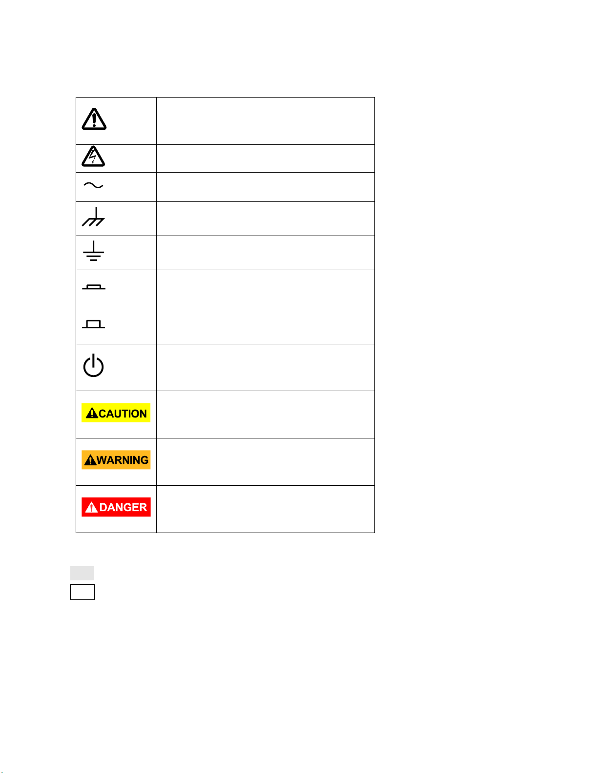
Safety Symbols
Refer to the user manual for warning
information to avoid hazard or personal
injury and prevent damage to instrument.
Electric Shock hazard
Alternating current (AC)
Chassis (earth ground) symbol.
Ground terminal
On (Power). This is the In position of the
power switch when instrument is ON.
Off (Power). This is the Out position of the
power switch when instrument is OFF.
Off (Supply). This is the AC mains
connect/disconnect switch on top of the
instrument.
CAUTION indicates a hazardous situation
which, if not avoided, will result in minor or
moderate injury
WARNING indicates a hazardous situation
which, if not avoided, could result in death
or serious injury
DANGER indicates a hazardous situation
which, if not avoided, will result in death or
serious injury.
Notations
TEXT – Denotes a softkey.
TEXT – Denotes a front panel button.
viii
Page 10

Contents
Safety Summary ..................................................................................................................... i
Compliance Statements ............................................................................................................... vi
Safety Symbols ........................................................................................................................... viii
Notations ............................................................................................................................ viii
1 General Information ...................................................................................................... 15
1.1 Product Overview ............................................................................................................ 15
1.2 Package Contents ............................................................................................................ 15
1.3 Product Dimensions ......................................................................................................... 16
1.4 Front Panel....................................................................................................................... 17
Front Panel Description ................................................................................................... 17
1.5 Rear Panel ........................................................................................................................ 18
Back Panel Description .................................................................................................... 18
1.6 Display Information ......................................................................................................... 19
User Interface Description .............................................................................................. 19
User Interface Functionality ............................................................................................ 20
2 Getting Started.............................................................................................................. 23
2.1 Input Power Requirements ............................................................................................. 23
2.2 Line Voltage and Fuse Requirements .............................................................................. 23
2.3 Preliminary Check ............................................................................................................ 25
Security Lock .................................................................................................................... 25
Verify AC Input Voltage ................................................................................................... 25
Connect Power ................................................................................................................ 25
Adjust the Support Feet .................................................................................................. 26
2.4 Power-on Inspection........................................................................................................ 26
Self-Test ........................................................................................................................... 27
Self-Calibration ................................................................................................................ 27
Check Model and Firmware Version ............................................................................... 27
Connect the Probe ........................................................................................................... 27
Probe Compensation ....................................................................................................... 27
Probe Safety .................................................................................................................... 28
Probe Attenuation ........................................................................................................... 29
3 Main Functions and Operating Descriptions ................................................................... 30
3.1 Menu and Control Buttons .............................................................................................. 30
3.2 Connectors ....................................................................................................................... 32
Analog and Digital Connectors ........................................................................................ 32
Miscellaneous Connectors .............................................................................................. 32
ix
Page 11

Rear Panel Connectors .................................................................................................... 33
3.3 Vertical System ................................................................................................................ 33
To Enable the Channel ..................................................................................................... 34
Adjust the Vertical Scale .................................................................................................. 34
Adjust the Vertical Position ............................................................................................. 35
Specify Channel Coupling ................................................................................................ 35
Specify Bandwidth Limit .................................................................................................. 35
Specify Probe Attenuation Factor ................................................................................... 36
Specify Channel Input Impedance ................................................................................... 36
Specify the Amplitude Unit ............................................................................................. 36
Deskew ............................................................................................................................ 36
Inverting a Waveform...................................................................................................... 36
3.4 Horizontal System ............................................................................................................ 37
Horizontal Scale Knob ...................................................................................................... 38
Adjust Trigger Delay ........................................................................................................ 38
Roll mode ......................................................................................................................... 38
The Zoom Function .......................................................................................................... 39
3.5 Run Control ...................................................................................................................... 40
3.6 Multi-Function Control .................................................................................................... 41
3.7 Universal Knob ................................................................................................................. 42
Adjust the waveform intensity ........................................................................................ 42
Universal Knob................................................................................................................. 42
3.8 On-line Help ..................................................................................................................... 42
4 Sample System Configuration ........................................................................................ 44
4.1 Run Control ...................................................................................................................... 44
4.2 Overview of Sampling ...................................................................................................... 44
Sampling Theory .............................................................................................................. 44
Sampling Rate .................................................................................................................. 44
Oscilloscope Bandwidth and Sample Rate ...................................................................... 46
4.3 Memory Depth ................................................................................................................ 47
4.4 Sampling Mode ................................................................................................................ 48
4.5 Waveform Interpolation Method .................................................................................... 48
4.6 Acquisition Mode ............................................................................................................. 51
Normal mode (default) .................................................................................................... 51
Peak Detect ..................................................................................................................... 51
Average ............................................................................................................................ 52
Eres (Enhanced Resolution) ............................................................................................. 54
4.7 Horizontal Format ............................................................................................................ 55
4.8 Sequence Mode ............................................................................................................... 56
Using the Sequence Mode: ............................................................................................. 56
Replaying a sequence of captured waveforms ............................................................... 57
5 Trigger .......................................................................................................................... 58
x
Page 12

5.1 Overview of triggering ..................................................................................................... 58
5.2 Auto Setup ....................................................................................................................... 59
5.3 Setting the Trigger ........................................................................................................... 59
5.4 Trigger Source .................................................................................................................. 60
5.5 Trigger Mode ................................................................................................................... 60
5.6 Trigger Level .................................................................................................................... 61
5.7 Trigger Coupling ............................................................................................................... 62
5.8 Trigger Hold Off ............................................................................................................... 62
5.9 Noise Rejection ................................................................................................................ 63
5.10 Trigger Types ................................................................................................................... 64
Edge Trigger ..................................................................................................................... 65
Slope Trigger .................................................................................................................... 66
Pulse Trigger .................................................................................................................... 68
Video Trigger ................................................................................................................... 70
Window Trigger ............................................................................................................... 73
Interval Trigger ................................................................................................................ 75
DropOut Trigger............................................................................................................... 76
Runt Trigger ..................................................................................................................... 79
Pattern Trigger................................................................................................................. 81
Serial Trigger .................................................................................................................... 83
6 Math Functions ............................................................................................................. 93
6.1 Math Operations and Their Units .................................................................................... 93
6.2 Addition and Subtraction................................................................................................. 93
6.3 Multiplication and Division .............................................................................................. 94
6.4 FFT (Fast Fourier Transform) ........................................................................................... 94
6.5 Differentiation ................................................................................................................. 96
6.6 Integration ....................................................................................................................... 97
6.7 Square Root ..................................................................................................................... 99
7 Cursors ......................................................................................................................... 100
7.1 Manual ........................................................................................................................... 100
7.2 Track .............................................................................................................................. 101
8 Auto Measurement ...................................................................................................... 102
8.1 Type of Measurement ................................................................................................... 103
Voltage Measurements ................................................................................................. 103
Time Measurements ..................................................................................................... 104
Delay Measurements .................................................................................................... 104
8.2 Statistics ......................................................................................................................... 105
8.3 Gate ............................................................................................................................... 105
8.4 To Clear Measurement Parameters .............................................................................. 106
8.5 All Measure .................................................................................................................... 106
xi
Page 13

9 Display Settings ............................................................................................................ 106
Display Type ................................................................................................................... 106
Color-Grade ................................................................................................................... 108
Persistence .................................................................................................................... 109
Clear the Display ............................................................................................................ 109
Grid Type ....................................................................................................................... 110
Grid Brightness .............................................................................................................. 110
Waveform Intensity ....................................................................................................... 110
Transparency ................................................................................................................. 110
10 Save and Recall ............................................................................................................ 112
10.1 Save Type ....................................................................................................................... 112
Setups ............................................................................................................................ 112
Reference ...................................................................................................................... 112
Binary ............................................................................................................................. 112
BMP (screen picture) ..................................................................................................... 112
CSV ................................................................................................................................. 112
MATLAB® ..................................................................................................................... 113
10.2 Setup Internal Save and Recall ...................................................................................... 113
Save setup to internal memory ..................................................................................... 113
Load setup from internal memory ................................................................................ 113
10.3 External save and recall ................................................................................................. 113
External Save ................................................................................................................. 113
Recall an external file .................................................................................................... 114
10.4 File Management ........................................................................................................... 114
Create a New File or Folder ........................................................................................... 115
Delete a file or folder .................................................................................................... 116
Rename a file or a folder ............................................................................................... 116
Security erase ................................................................................................................ 116
11 Utility ........................................................................................................................... 117
11.1 View the System Status ................................................................................................. 117
11.2 Self Calibration ............................................................................................................... 117
11.3 Sound ............................................................................................................................. 118
11.4 Language ........................................................................................................................ 118
11.5 Pass/Fail ......................................................................................................................... 119
Perform a Pass/Fail Test ................................................................................................ 119
Save and Recall Test Mask ............................................................................................. 121
11.6 I/O Remote Communication .......................................................................................... 121
Communicating via USB ................................................................................................ 121
Communicating via a LAN.............................................................................................. 121
Auxiliary Output ............................................................................................................ 123
11.7 Quick-Cal ........................................................................................................................ 123
xii
Page 14

11.8 Update Firmware and Configuration ............................................................................. 124
11.9 Perform a Self-test ......................................................................................................... 125
Screen Test .................................................................................................................... 125
Keyboard Test ................................................................................................................ 125
LED Test ......................................................................................................................... 126
11.10 Screen Saver .................................................................................................................. 126
11.11 Option Management ..................................................................................................... 127
12 Reference Waveforms .................................................................................................. 128
To Save a Reference Waveform to Internal Memory ................................................... 129
To Display a Reference Waveform ................................................................................ 129
To Adjust the Reference Waveform Position ................................................................ 129
To Clear the Reference Waveform ................................................................................ 130
13 History Function ........................................................................................................... 130
14 Default Setup ............................................................................................................... 132
15 Serial Bus Decoding (DC2560) ....................................................................................... 135
15.1 I2C Serial Decode ........................................................................................................... 135
Setup for I2C Signals ...................................................................................................... 135
I2C Serial Decode ........................................................................................................... 135
15.2 SPI Serial Decode ........................................................................................................... 137
Setup for SPI Signals ...................................................................................................... 137
SPI Serial Decode ........................................................................................................... 139
15.3 UART/RS232 Serial Decode ........................................................................................... 141
Setup for UART Signals .................................................................................................. 141
UART Serial Decode ....................................................................................................... 142
15.4 CAN Serial Decode ......................................................................................................... 143
Setup for CAN Signals .................................................................................................... 143
CAN Serial Decode ......................................................................................................... 144
15.5 LIN Serial Decode ........................................................................................................... 146
Setup for LIN Signals ...................................................................................................... 146
LIN Serial Decode ........................................................................................................... 146
16 Digital Channels (LA2560 + LP2560) .............................................................................. 148
16.1 Connecting Digital Probes to Device under Test ........................................................... 148
16.2 Acquiring Digital Waveforms ......................................................................................... 149
16.3 Displaying Digital Channels ............................................................................................ 149
16.4 Turning a Single Digital Channel On or Off .................................................................... 151
16.5 Turning All Digital Channels On or Off ........................................................................... 151
16.6 Changing the Logic Threshold for Digital Channels ....................................................... 151
16.7 Displaying Digital Channels as a Bus .............................................................................. 152
xiii
Page 15

17 Arbitrary Waveform Generator (FG2560) ...................................................................... 153
17.1 Wave Types and Parameters ......................................................................................... 153
Sine Waveform .............................................................................................................. 155
Square Waveform .......................................................................................................... 155
Ramp Waveform............................................................................................................ 156
Pulse Waveform ............................................................................................................ 156
DC Waveform ................................................................................................................ 157
Noise Waveform ............................................................................................................ 157
Cardiac Waveform ......................................................................................................... 158
Gaus Pulse ..................................................................................................................... 159
17.2 Arbitrary Waveforms ..................................................................................................... 159
17.3 Output Impedance ......................................................................................................... 160
17.4 Set Default Values.......................................................................................................... 161
17.5 AWG Self Cal .................................................................................................................. 161
18 Troubleshooting ........................................................................................................... 162
19 Specifications ............................................................................................................... 164
Test Equipment Depot - 800.517.8431 - 99 Washington Street Melrose, MA 02176
TestEquipmentDepot.com
xiv
Page 16

1 General Information
DSO Model
2563
2565
2566
2567
2568
2569
MSO Model
2563-MSO
2565-MSO
2566-MSO
2567-MSO
2568-MSO
2569-MSO
Bandwidth
70 MHz
100 MHz
200 MHz
200 MHz
300 MHz
300 MHz
Channels
4 4 2 4 2
4
1.1 Product Overview
The B&K Precision 2560 series includes 6 Mixed Signal Oscilloscopes (MSO) and 6 Digital Storage
Oscilloscopes (DSO). The MSOs and DSOs have high bandwidths that allows them to capture
signals with real time sampling rates of up to 2 GSa/s. All of the oscilloscopes have a waveform
update rate up to 140 thousand waveforms per second and a maximum memory depth of 140
million points. A screen with up to 256 levels of intensity and a color display allow these units to
capture and display more details of a signal for subsequent analysis.
Features:
Single channel real-time sampling rate of up to 2 GSa/s. Dual channel interleaved 1 GSa/s
Up to 140 thousand points of memory depth
8” Color TFT LCD display (800x480 pixels)
Trigger types: Edge, Slope, Pulse, Video, Window, Runt, Interval, DropOut, Pattern, Serial
Waveform acquisition function
36 automatic measurements: voltage and time parameters
Standard interfaces: USB Host, USB Device (USBTMC), Pass/Fail signal output, LAN, trigger
output signal
Optional features
o MSO license option (LA2560): Enables the 16 digital channels and the Digital button.
The 16 channel logic probe (LP2560) is used conjunction with the license.
o Decode license option (DC2560): Serial decode functions: I2C, SPI, UART, CAN, LIN.
Enables the Decode button.
o Function generator option (FG2560). 25 MHz function generator and arbitrary
waveform generator
1.2 Package Contents
Please inspect the instrument mechanically and electrically upon receiving it. Unpack all items
from the shipping carton and check for signs of physical damage that may have occurred during
transportation. Report any damage to the shipping agent immediately. Save the original packing
carton for possible future reshipment. Every instrument is shipped with the following contents:
1 x 256X digital storage or mixed signal oscilloscope
1 x AC power cord
1 x USB type A to type B cable
Page 17
Passive oscilloscope probe, one per channel
1 x Digital logic probe (MSO models only)
1 x Certificate of calibration
1 x Quick start guide
Verify that all items above are included in the shipping container. If anything is missing, please
contact B&K Precision.
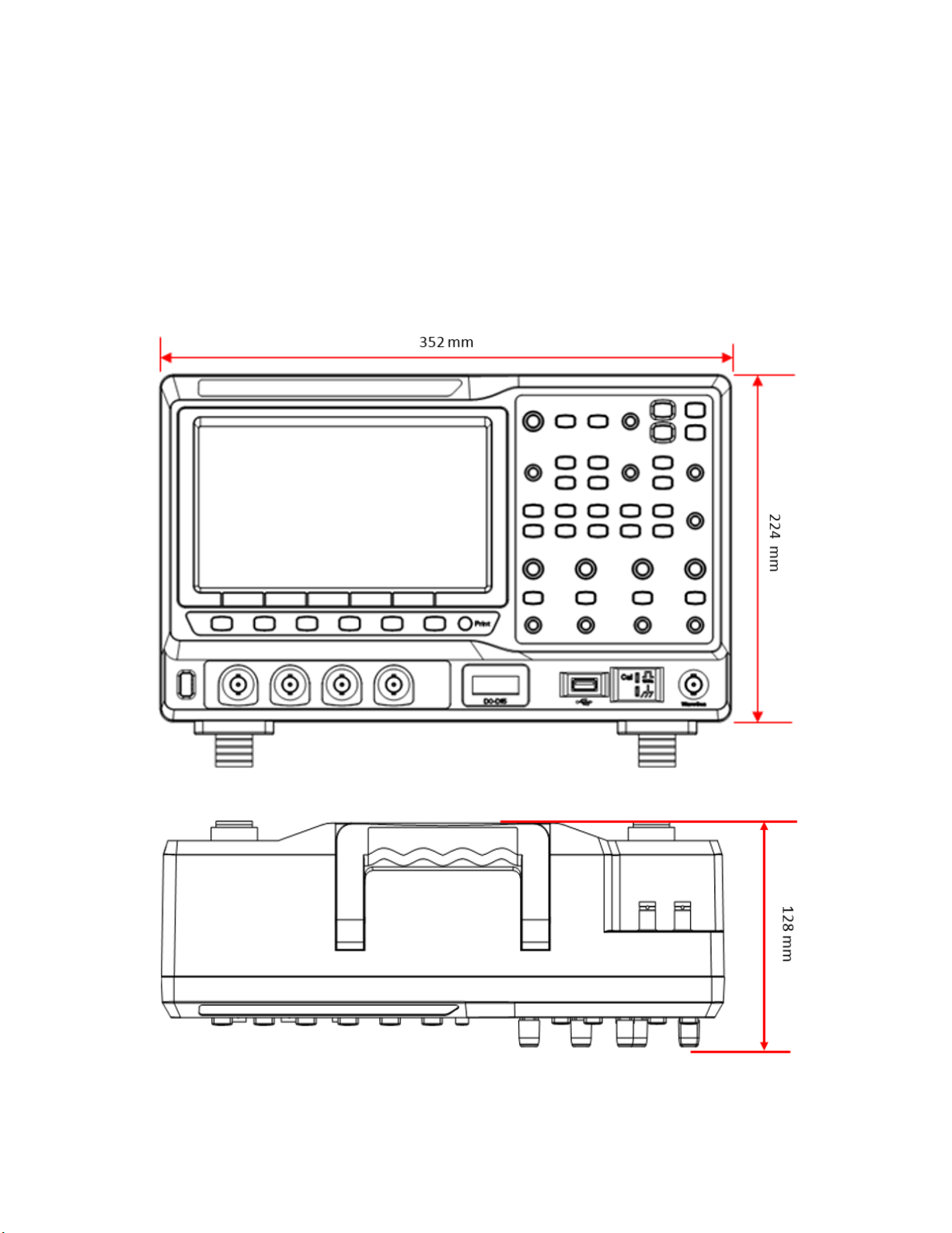
1.3 Product Dimensions
Figure 1 - Product dimensions
16
Page 18
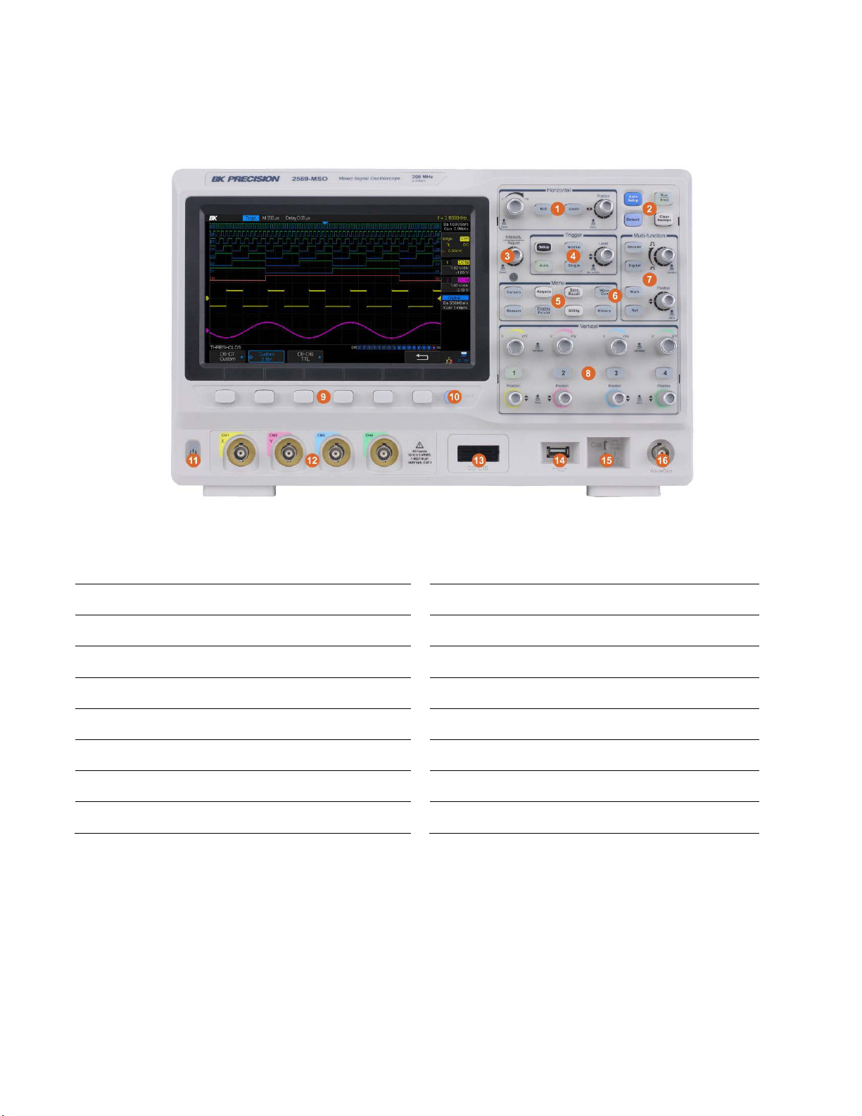
1.4 Front Panel
①
Horizontal Control
⑨
Menu Softkeys
②
Auto/Run Control
⑩
Print Button
③
Universal Knob
⑪
Power On/Off Button
④
Trigger Control
⑫
Analog Inputs
⑤
Function Menus
⑬
Digital Inputs
⑥
Wave Gen Control
⑭
USB Host Port
⑦
Multi-function control
⑮
Probe Compensation Terminal
⑧
Vertical Control
⑯
Wave Gen Output
Figure 2 - Front panel
Front Panel Description
17
Page 19
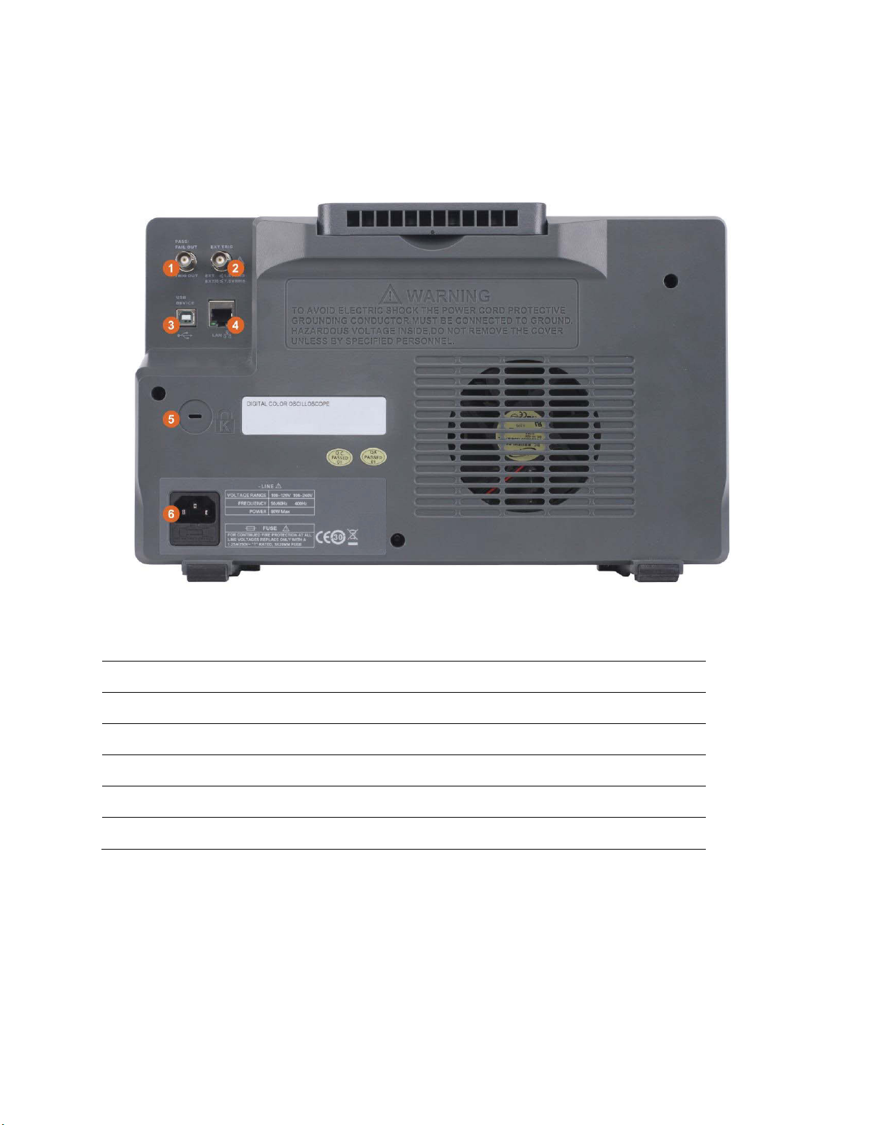
1.5 Rear Panel
①
Pass/Fail or trigger output
②
External trigger input
③
USB④LAN⑤Safety lock (Kensington style)
⑥
AC power input connector
The following images show back and side panel connection locations.
Back Panel Description
Figure 3 – Rear panel
18
Page 20
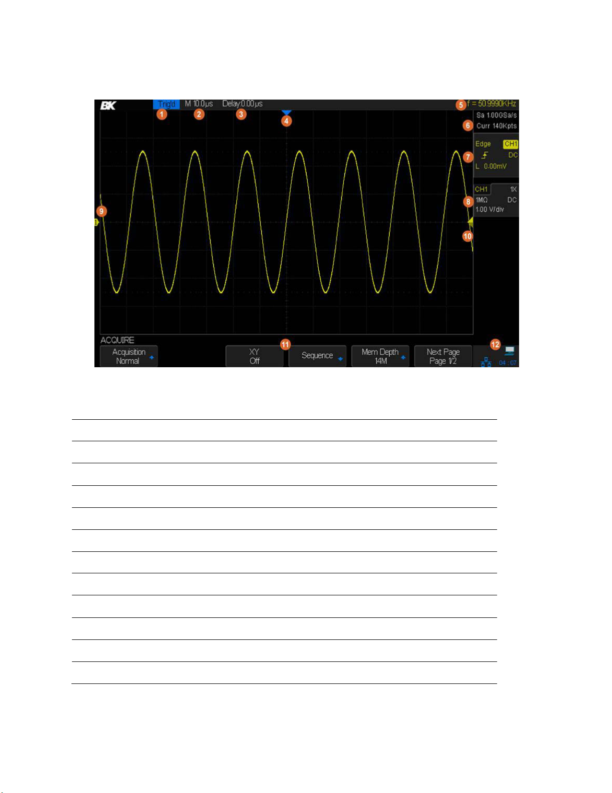
1.6 Display Information
①
Operating state
②
Horizontal timebase setting
③
Trigger point position relative to center of display
④
Trigger point on waveform
⑤
Frequency counter (measures frequency of trigger signal)
⑥
Sample rate and memory depth
⑦
Trigger settings
⑧
Channel settings
⑨
Channel label and zero volts position marker
⑩
Trigger voltage level (color indicates trigger source)
⑪
Softkeys (capitalized word shows with button's menu is in use)
⑫
I/O connection status
User Interface Description
Figure 4 – Display screen
19
Page 21
Test Equipment Depot - 800.517.8431 - 99 Washington Street Melrose, MA 02176
TestEquipmentDepot.com
User Interface Functionality
1. Operating state
The states are Arm, Ready, Trig’d (triggered), Stop, Auto.
2. Horizontal Timebase
Represents the time per division on the horizontal axis. Turning the horizontal scale knob (the
left knob in the Horizontal control area) changes the time per division setting from 1 ns/div to 50
s/div.
3. Trigger position parameter (delay)
Shows the time difference between a trigger point and the center of the screen. Turn clockwise
or counterclockwise to make the waveform move right or left, which will cause the delay
parameter to decrease or increase, respectively. Press the horizontal position knob to reset the
delay parameter to zero (the trigger position mark will then be in the middle of the screen).
4. Trigger position mark
Displays the trigger point on the waveform. The delay parameter is zero at this point.
5. Frequency counter
Displays the frequency of the trigger source waveform.
6. Sample rate/memory depth
Displays the current sample rate (Sa) and memory depth (Curr) of the oscilloscope. Use the
horizontal scale knob to modify the parameters.
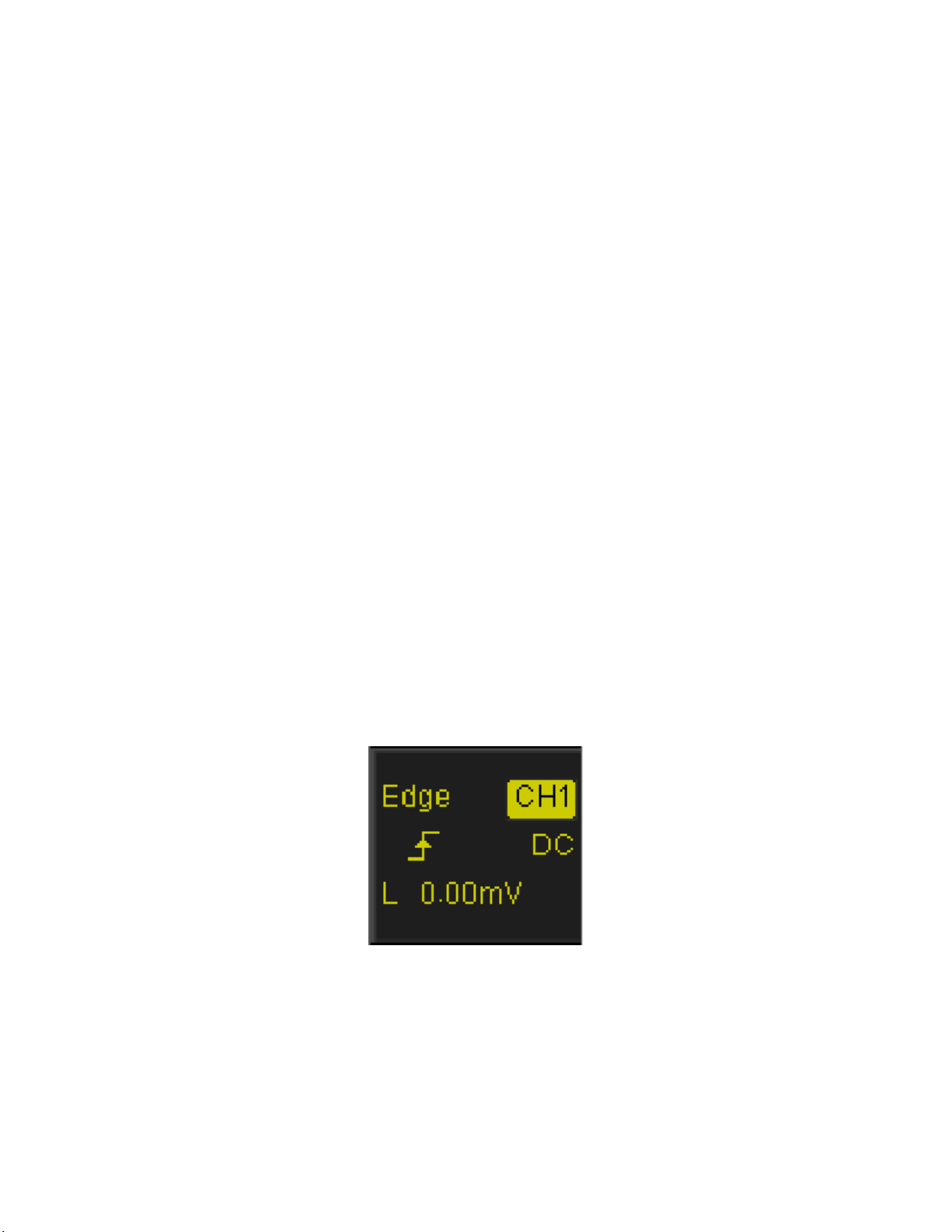
7. Trigger settings
The trigger settings are always displayed on the upper-right side of the screen.
Figure 5 - Trigger settings display
20
Page 22
Icon
Function
Description
Trigger Type
Displays the currently selected trigger type and trigger
condition setting. Different labels are displayed when
different trigger types are selected.
Trigger Source
Displays the trigger source currently selected. Different
labels are displayed when different trigger source are
selected and the color of the trigger parameter area will
change accordingly.
Trigger Slope
Displays the current trigger slope.
Trigger Coupling
Displays the coupling mode (DC/AC/LF Reject/HF Reject)
of the current trigger source.
Trigger Level
Displays the trigger voltage or current level of the
current waveform. Press the Universal Knob to set the
level to 50% of the waveform's amplitude.
Table 1 - Trigger settings
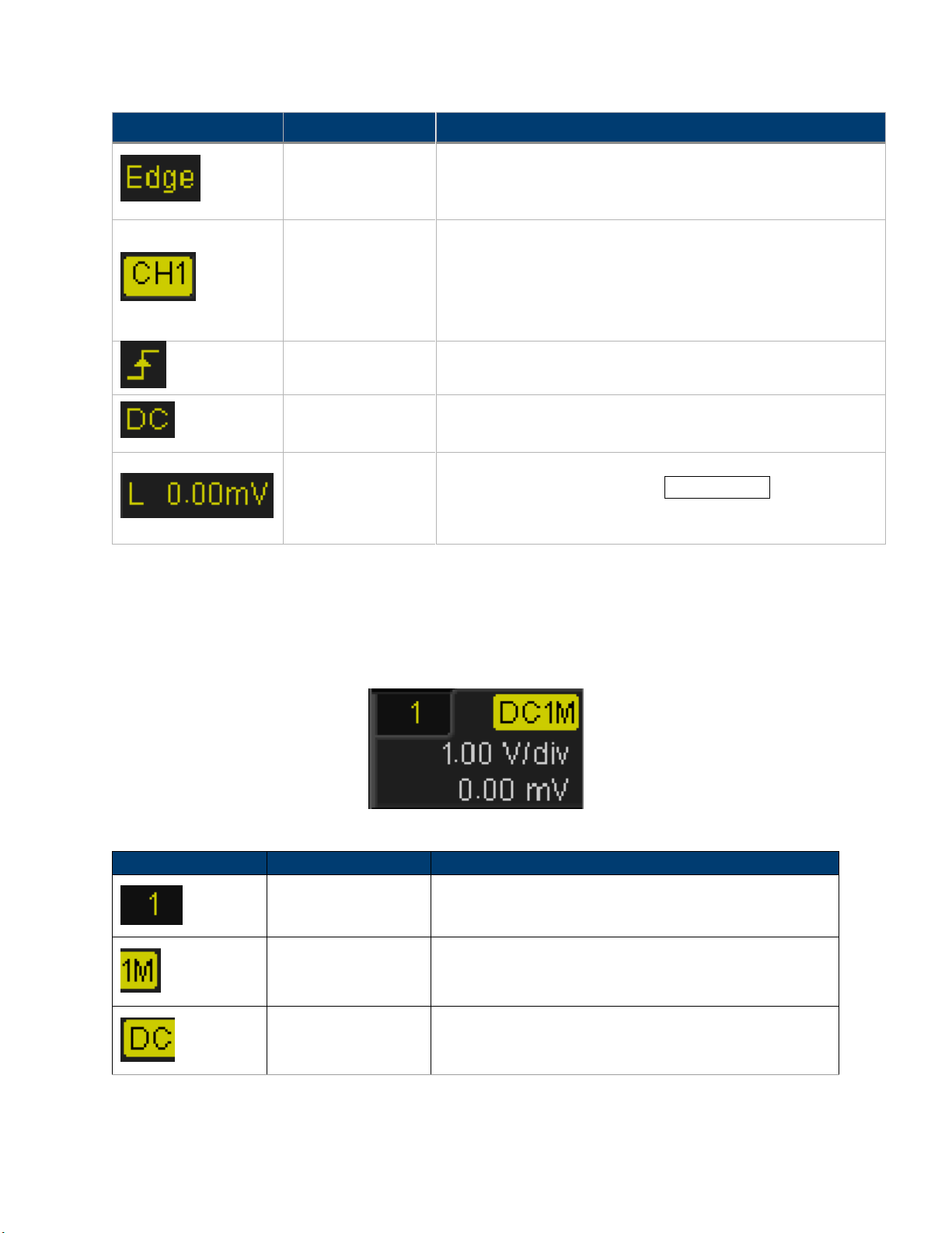
Icon
Function
Description
Channel Number
Represents the channel number
Input impedance
Displays the currently selected input impedance of
the channel (1 MΩ or 50 Ω).
Channel coupling
Displays the coupling mode of the current channel.
The modes are DC, AC, and GND.
8. Channel settings
The channel settings are displayed when the represented channel is enabled. If no channel is
enabled there will be no channel setting display.
Figure 6 - Channel settings display
21
Page 23
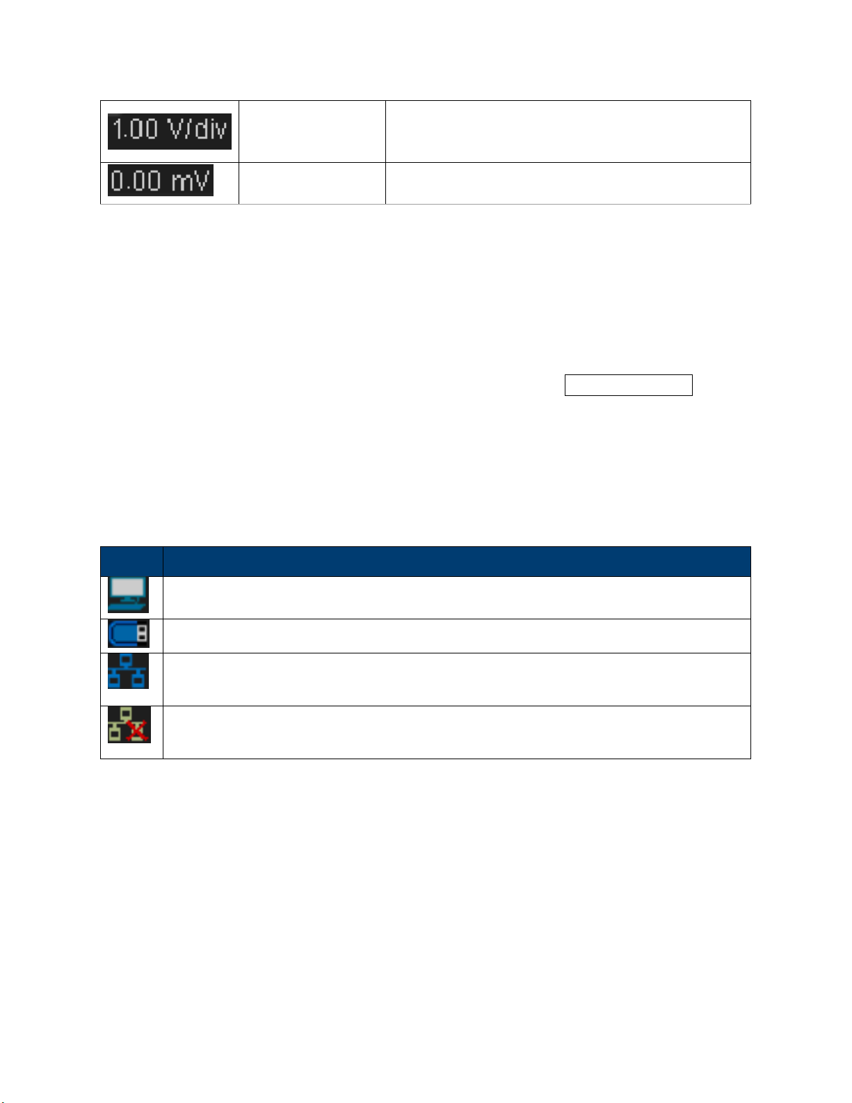
Vertical Scale
Represents the voltage value of each vertical main
division on the screen.
Vertical Offset
Represents the vertical displacement of the trace in
voltage above or below the center of the screen.
Table 2 - Trigger settings
Icon
Function
Displays the connection status of the USB host, USB device, and LAN port. Indicates
when the USB Device (USBTMC) is connected.
Indicates that the USB Host is connected.
Indicates there is a LAN connection.
Indicates there is no LAN connection.
9. Channel label/waveform
Indicates the active channel. Different channels are displayed in different colors and the color of
the waveform matches the color of the channel on the front panel. The indicator on the left-hand
side, with the channel number in it, points to the channel's current point on the vertical axis.
10. Trigger level position
Displays the position of the current channel trigger level. Press the Trigger Level Knob to reset
the trigger voltage to the center (50% point) of the waveform.
11. Softkeys
The six softkeys display the current menu’s options. The left most capitalized word above the
softkeys reflects the button pressed on the main panel.
12. I/O connection status
Table 3 - I/O Connection Status
22
Page 24

2 Getting Started
The included AC power cord is safety certified for this instrument operating in rated
range. To change a cable or add an extension cable, be sure that it can meet the
required power ratings for this instrument. Any misuse with wrong or unsafe cables
will void the warranty.
Before replacing fuse, disconnect AC input power cord first to prevent electric shock.
Only use same rating of the fuse. Using a different rated fuse may damage the
instrument.
Model
Fuse Specification
All Models
T 1.25 A, 250 V
Before connecting and powering up the instrument, please review and go through the
instructions in this chapter.
2.1 Input Power Requirements
The supply has a universal AC input that accepts line voltage input within:
Voltage: 110 V to 240 V (±10%)
Frequency: 50 Hz to 60 Hz (±5%) / 400 (±5%)
Power supply power range: ≤ 80VA
Before connecting to an AC outlet or external power source, make sure that the power switch is
in the OFF position and verify that the AC power cord. Once verified, connect the cable firmly.
2.2 Line Voltage and Fuse Requirements
An AC input fuse is necessary when powering the instrument. The fuse is located at the back of
the instrument. In the event the fuse needs to be replaced, make sure the AC input power cord
is disconnected from the instrument before replacing it.
Table 4 - Fuse Requirements
Follow the steps below to check or change fuse.
Check and/or Change Fuse
1 Locate the fuse box next to the AC input connector in the rear panel.
23
Page 25
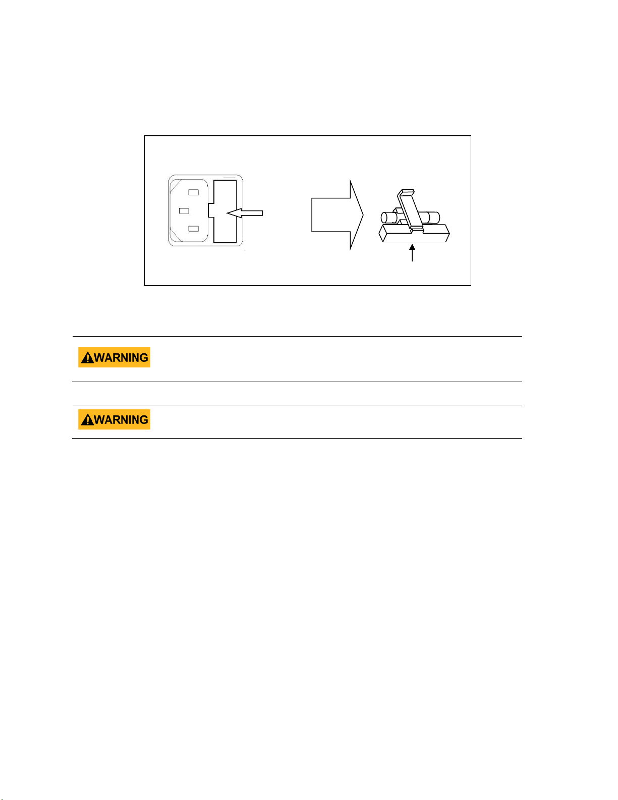
2 With a small flat blade screwdriver, insert into the fuse box slit to pull and slide
Do not connect power to the instrument until the line voltage is configured
correctly. Applying an incorrect line voltage or configuring the line voltage
improperly will damage the instrument and void all warranty.
Any disassembling of the case or changing the fuse not performed by an authorized
service technician will void the warranty of the instrument.
out the fuse box as indicated below.
3 Check and replace fuse (if necessary).
Figure 7 - Replacing Fuse
Test Equipment Depot - 800.517.8431 - 99 Washington Street Melrose, MA 02176
TestEquipmentDepot.com
24
Page 26
2.3 Preliminary Check
Complete the following steps to verify that the oscilloscope is ready for use.
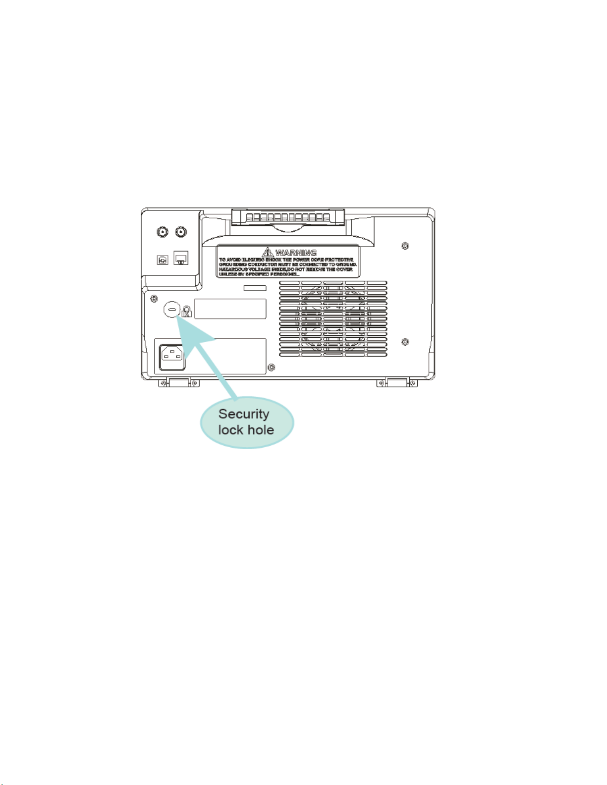
Security Lock
Provisions for a Kensington-style lock are provided on the rear panel of the oscilloscope (a lock is
not included). Align the lock with the lock hole and insert, turn the key clockwise to lock the
instrument and then remove the key from the lock.
Figure 8 - Security lock
Verify AC Input Voltage
Verify the proper AC voltages are available to power the instrument. The AC voltage range must
meet the acceptable specification given in the safety section.
Connect Power
Connect the AC power cord to the AC receptacle in the rear panel of the oscilloscope and the
plug the opposite end of the power cord into an outlet.
25
Page 27
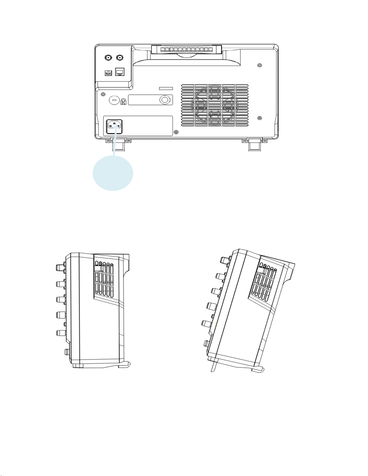
Figure 9 - Connecting to the power line
Power
socket
Adjust the Support Feet
Pull out the support feet to tilt the oscilloscope backwards for better visibility.
If
Figure 10 - Supporting feet adjustment
2.4 Power-on Inspection
After connecting the oscilloscope to the AC power, press the power switch at the lower left
corner of the oscilloscope to turn the instrument on (the LEDs in all translucent keys will turn on).
26
Page 28

During the start-up process, the instrument performs a series of self-tests and displays a splash
Oscilloscope
Model
Bandwidth
Channels and number of
probes supplied
Probe
Model
Probe Type
2563
70 MHz
4
PR150B
150 MHz, X1/X10
2565
100 MHz
4
PR150B
150 MHz, X1/X10
2566
200 MHz
2
PR250B
250 MHz, X10
2567
200 MHz
4
PR250B
250 MHz, X10
2568
300 MHz
2
PR500B
500 MHz, X10
2569
300 MHz
4
PR500B
500 MHz, X10
screen. After the self-tests are finished, the normal screen will be displayed and the oscilloscope
is ready for use.
To turn off the scope, press and hold the power button. Hold the button down until the scope
turns off.
Self-Test
The instrument has the capability of doing self-tests for the screen, keyboard, LED-backed
buttons.
To perform the self-test, please refer to the Perform a Self-test section for further instructions.
Self-Calibration
This option runs an internal self-calibration procedure that will check and adjust the instrument.
To perform the self-calibration, please refer to the Self Calibration section for further
instructions.
Check Model and Firmware Version
The model and firmware version can be checked by pressing the Utility key and pressing the
System Status softkey. The number of startup times, software version, FPGA version, hardware
version, product type, serial number and Scope ID will be displayed. Press the Single key to exit.
Connect the Probe
B&K Precision provides passive probes for the 2560 Series oscilloscope. Please refer to the
probe’s user manual for more detailed information. Before connecting probes, please read and
understand the Probe Safety section.
Table 5 Analog Probes
Connect the BNC terminal of the probe to one of the channel BNC connectors on the front panel
(see the safety information below). Connect the probe tip to the circuit point under test and the
ground alligator clip of the probe to a grounded point in the circuit.
Probe Compensation
All oscilloscope probes should be properly compensated before their first use with the
oscilloscope. A non-compensated or inadequate compensated probe can cause inaccurate
measurements. The following steps illustrate the proper probe compensation procedure.
27
Page 29
1. Press the Default button to reset the oscilloscope to its factory default setup state.
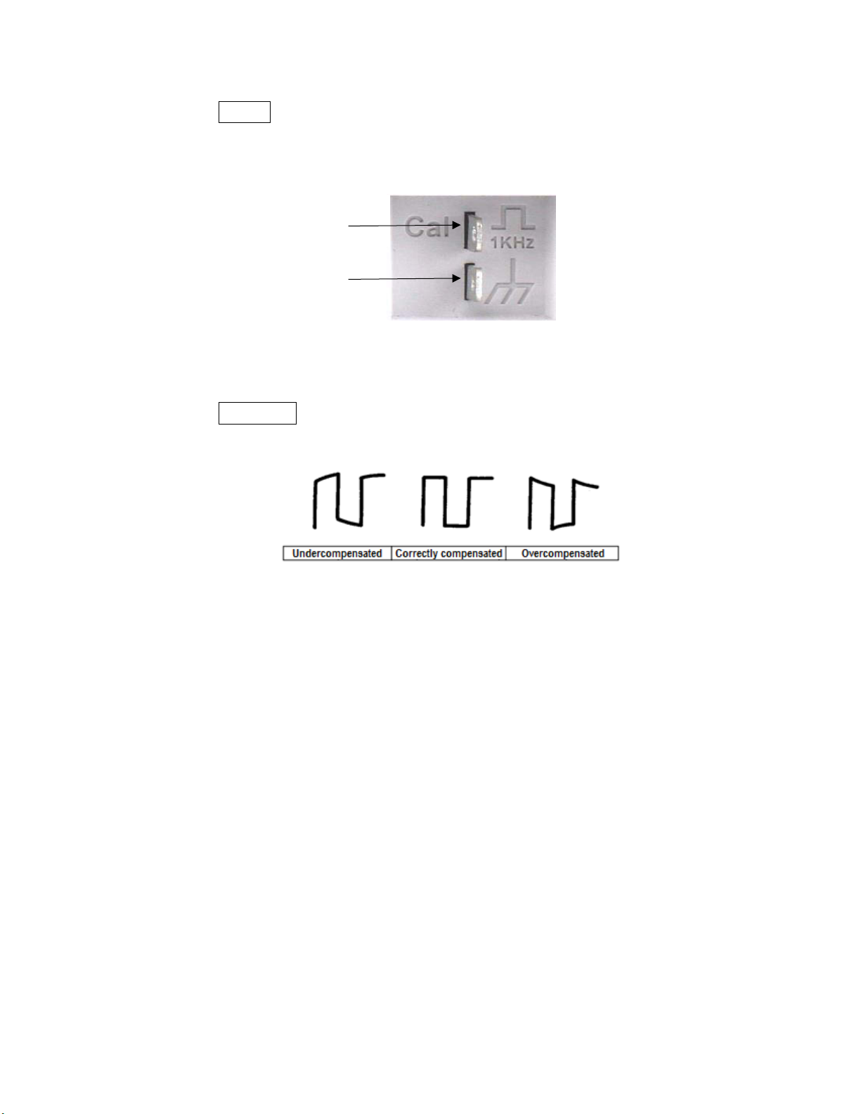
Ground terminal
Compensation signal
output terminal
2. Connect the ground alligator clip of the probe to the ground terminal under the probe
compensation signal output terminal.
Figure 11 -Compensation terminals
3. Connect the probe to channel 1's BNC connector. Connect the tip of the probe to the
compensation signal output terminal.
4. Press the Auto Setup button.
5. Observe the waveform on the screen and compare it to the following figure.
Figure 12 -Waveform compensation
6. Use a nonmetallic flat-head screwdriver to adjust the low-frequency compensation
adjustment screw on the probe until the waveform matches the “Correctly compensated”
waveform above.
We recommend you check probe compensation daily or after the probe has been used on
another instrument.
Probe Safety
A guard around the probe body provides a finger barrier for protection from electric shock.
28
Page 30
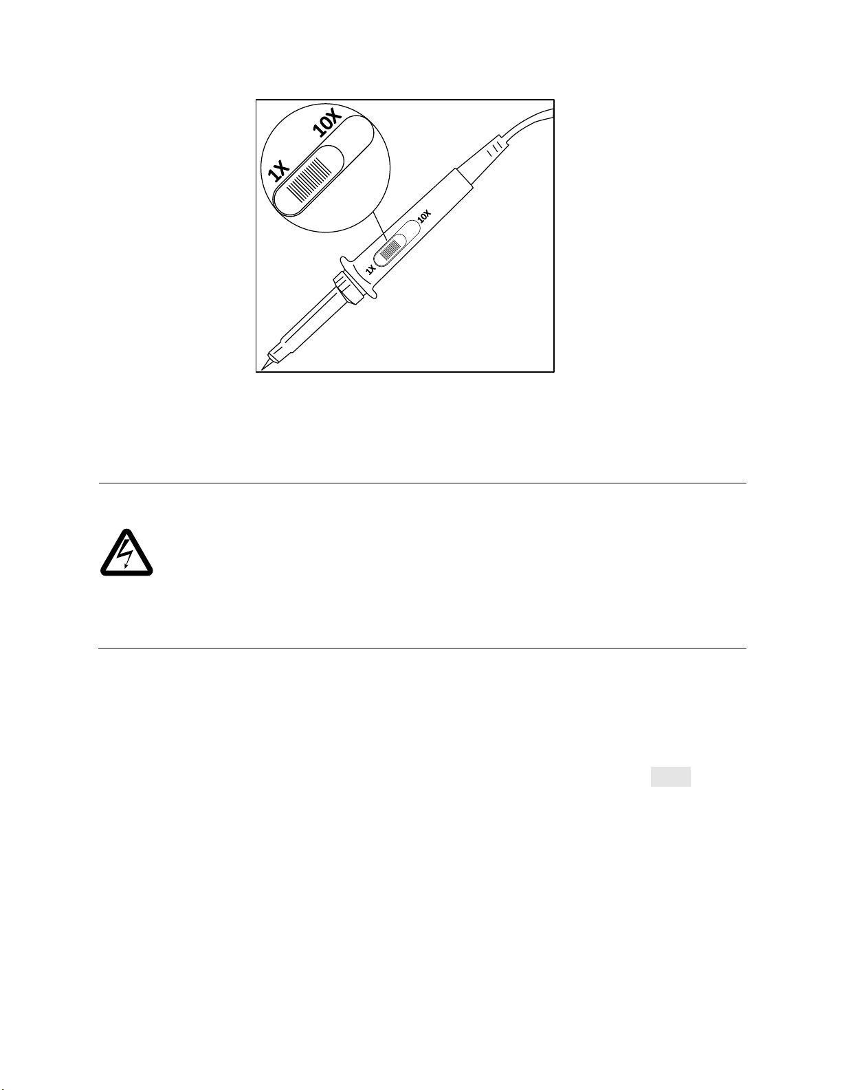
Figure 13 – Oscilloscope probe
WARNING: SHOCK HAZARD
To avoid electric shock when using the probe, please make certain that the insulated wire of
the probe is in good condition and do not touch the metallic parts of the probe when it is
connected to a high voltage.
Do not connect the probe's ground lead (e.g., using the supplied alligator clip) to any point in
a circuit that is not at ground potential. If you're not sure whether a point you want to
connect to is at ground potential, first check it with a known-working high-impedance digital
voltmeter.
Connect the probe to the oscilloscope and connect the ground terminal to ground before you
take any measurements.
Probe Attenuation
Probes have attenuation factors that can affect the vertical display of the signal. Before making
measurements with the probe, verify the probe's attenuation matches the attenuation setting of
the oscilloscope channel it is connected to. Push the numbered button corresponding to the
channel the probe is connected to and ensure the attenuation factor shown on the Probe softkey
matches that of the probe. Failure to do this will result in significant measurement error.
Test Equipment Depot - 800.517.8431 - 99 Washington Street Melrose, MA 02176
TestEquipmentDepot.com
29
Page 31

3 Main Functions and Operating Descriptions
Button
Purpose
Turns the measurement cursors on and off. These are used to make voltage and
time measurements on the displayed waveform. Manual and tracking modes are
available.
To use your oscilloscope effectively, you need to learn about the following oscilloscope functions:
• Menu and Control Buttons
• Connectors
• Vertical System
• Horizontal System
• Run Control
• Universal knob
• Display System
• Measuring waveforms System
• Utility System
• Storage System
• Online Help function
In the following material, ButtonName indicates a button on the right-hand main panel of the
oscilloscope. Softkey denotes a softkey for a menu selection on the softkeys below the screen.
3.1 Menu and Control Buttons
Figure 14 - Menu
Pressing the white buttons enter the indicated menu. The lighted buttons show whether the
indicated feature is on and off besides entering the feature's menu.
30
Page 32

This menu lets the user choose the acquisition method (normal, peak-detect,
averaging, and Eres (enhanced resolution), turn XY mode on and off, turn the
sequence feature on for capturing sequences of waveforms, set the size of the
waveform memory buffer, set the interpolation type (Sinx/x or linear), and set the
acquisition mode (fast or slow).
The save/recall menu lets you save waveforms and instrument settings to internal
memory or an external flash drive device connected to the front-panel USB
connector. You can save the instrument settings, a reference waveform, or the
waveform(s) displayed on the screen (either as a bitmap or in binary, CSV, or
MATLAB formats).
Turn on and off the optional function generator with 11 types of waveforms.
Turn on and off the oscilloscope's measuring functions. A variety of waveform
parameters can be measured (e.g., amplitude, frequency/period, rise time, etc.).
An All Measure button lets you see all of these parameters at once. You can also
collect the statistics mean, minimum, maximum, standard deviation, and count
(number of samples) for selected parameters over time.
This menu lets you set the display type (dots: the sampled points, vectors: lines
are drawn between the dots), turn on the Color-Grade display (a type of
histogram using color), persistence (how long a particular trace stays on the
screen), the grid type and intensity, the trace intensity, and the transparency of
dialog boxes. It is also used to quickly turn the persistence on and off.
Perform utility tasks such as:
Viewing information about the instrument (model, serial number,
firmware version, etc.)
Self-calibration
Turn the key click sound on and off
Select language
Set up pass/fail testing and USB/LAN settings
Update the firmware or configuration from a flash drive
Perform a self-test (screen, keyboard, or LED)
Set the screen-saver time
Add options and view which options are installed
Turn history mode on and off. The history feature allows you to save a series of
waveform traces, then review them one-at-a-time or display them sequentially at
a specified rate. The Sequence softkey in the Acquire menu lets you set up how
many waveform traces (frames) you want to record. Up to 80,000 frames can be
recorded.
31
Page 33

3.2 Connectors
Analog and Digital Connectors
Figure 15 – Analog and digital connectors
Analog Input Connectors (CH1, CH2, CH3, and CH4): connect your probes and analog
signals to these BNC connectors.
Digital Input Connectors (DO-D15): connect the logic analyzer digital breakout cable to
this connector (cable provide and digital functions enabled with the MSO option).
Miscellaneous Connectors
Figure 16 - Miscellaneous connectors
USB Host: Setups, waveforms, screenshots, and CSV for files can be saved to or recalled
from a USB device.
Probe Compensation: 1 kHz square wave for probe compensation.
WaveGen: Output for the optional built-in function generator.
32
Page 34
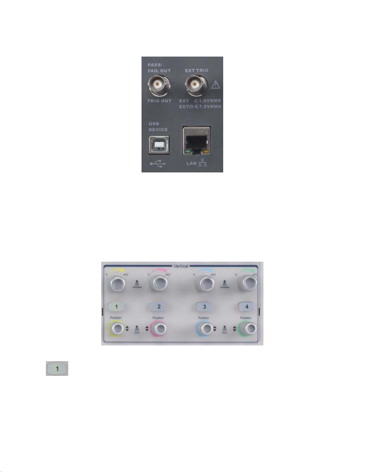
Rear Panel Connectors
Analog Input
Channels
The colors correspond to the color of the traces on the
screen and on the input channel connectors. Press the
numbered button to turn the corresponding channel
trace on and off and display the channel's menu.
Figure 17 - Rear panel connectors
PASS/FAIL TRIG OUT: BNC connection.
Rear panel external trigger input: BNC connection.
USB: USB port for remote device control.
LAN: Ethernet connection.
3.3 Vertical System
Figure 18 - Vertical
33
Page 35

Vertical Scale
Knob
Adjust the volts/division for the channel. As this knob is
adjusted, the displayed waveform will change its height
on the screen. Press the knob to switch between coarse
and fine adjustments. The scale setting is displayed in the
channel information at the right side of the screen.
Vertical
Position Knob
Adjust the waveform position (offset) on the screen. The
offset voltage or current will be shown at the right side
of the screen under the scale setting. Press the knob to
set the offset to zero.
To Enable the Channel
Note: To stop displaying the channel's trace on the screen, press the channel button until its light goes
out.
The oscilloscope's analog channels vertical settings are independently controlled. The controls
for each channel are analogous. CH1 will be used in the following discussion.
Connect a signal to the CH1 analog input connector. Press the 1 button in the VERTICAL control
area of the front panel to turn on channel 1. The channel can be displayed on the screen when
the 1 button is lit. The channel's vertical menu is displayed on the softkeys and you will see the
CH1 annotation at the left of the screen above the softkeys, which tells you which channel's
settings can be modified by the softkeys.
Adjust the Vertical Scale
By pressing the vertical scale knob, the knob can be used for coarse or fine adjustments:
The coarse adjustment sets the vertical scale in 1-2-5 steps, such as 1 mV/div, 2 mV/div, 5
mV/div, 10 mV/div, etc. The range of the settings will depend on the probe attenuation factor
set. For an attenuation of 1X, the settings range from 500 µV/div to 10 V/div.
The fine adjustment changes the vertical scale in smaller increments (depending on the set
value). For example, if you set the coarse adjustment to 1 V/div and press the button to
change to fine adjustment, one counterclockwise click of the knob will change the scale to
1.02 V/div.
The fine adjust mode can be used to make the waveform take up the whole screen, which will
improve the resolution of measurements taken from the screen's graticule (i.e., the grid).
When the scale control is adjusted, the words Fine or Coarse will appear in the Adjust softkey
(you can use this softkey to toggle between fine and coarse adjustment modes).
To convert a vertical distance on the screen to a voltage or current, read the channel's scale value
from the right-hand side of the screen and multiply it by the number of vertical divisions covering
the feature of interest.
34
Page 36

Volts/div Setting
Range of Vertical Adjustment
2 mV/div to 100 mV/div
±1 V
102 mV/div to 1 V/div
±10 V
1.02 V/div to 10 V/div
±100 V
Test Equipment Depot - 800.517.8431 - 99 Washington Street Melrose, MA 02176
TestEquipmentDepot.com
Adjust the Vertical Position
Turn the VERTICAL Position knob to adjust the vertical position of the channel's waveform on the
screen. Push the knob to set the 0 volts or amperes position on the waveform to the center of
the screen. The current adjustment value is shown by the channel's marker on the left side of the
screen and in the channel's data on the right side of the screen.
The following table shows the range of vertical position adjustment according to the volts/div
setting (1X probe attenuation factor).
Table 6 - Volts/div scale vs. vertical position
Specify Channel Coupling
There are three channel coupling settings: DC, AC, and GND. Suppose the signal being input is a
square wave with DC offset.
When the coupling is set to DC, both the DC and AC components of the signal will be
displayed.
When the coupling is set to AC, the DC offset of the signal is blocked.
When the coupling is set to GND, both the DC offset and AC components of the signal are
both blocked.
Press the 1 button on the front panel, then press the Coupling softkey and turn the Universal
Knob to select the desired coupling mode. The default coupling is DC.
The current coupling mode is displayed in the channel label at the right side of the screen. You
can also press the Coupling softkey repeatedly to switch between the coupling modes.
Specify Bandwidth Limit
Set the bandwidth limit to reduce displayed noise. For example, the input signal is a pulse with
high frequency oscillations.
When the bandwidth limit is set to none, the high frequency components of the signal under
test can pass the channel.
When the bandwidth limit is set to 20MHz, the high frequency components above 20 MHz
are attenuated.
Press the 1 button on the front panel, then press the BW Limit softkey to select none or 20M.
The default setting is none. When the bandwidth limit is enabled, the character B will be
displayed in the channel label at the right side of the screen.
35
Page 37

Specify Probe Attenuation Factor
Set the channel's attenuation factor to match the attenuation of the probe you are using to
ensure correct voltage or current measurements. To do this, press the 1 button on the front
panel, then press the Probe softkey and turn the Universal Knob to select the desired
attenuation. Push the knob to select the chosen value. The default is 1X. You can also press the
Probe softkey repeatedly to change the channel's probe attenuation factor.
Specify Channel Input Impedance
Select the channel input impedance: 1 MΩ and 50 Ω. Do not exceed a voltage input of more than
5 V absolute value for a 50 Ω impedance input or 400 V absolute value for a 1 MΩ impedance
input. A high impedance of 1 MΩ minimizes loading the device under test.
Press the channel button on the front panel, then press the Impedance softkey to toggle between
1 MΩ and 50 Ω. The default is 1 MΩ. The channel's input impedance is displayed in the channel
label at the right side of the screen.
Specify the Amplitude Unit
You can display the channel's measurement unit as volts (V) or amperes (A). When the unit is
changed, the unit displayed in the channel label will change accordingly. The default setting is V.
1. Press the 1 button on the front panel to display the CH1 menu.
2. Press the Next Page softkey.
3. Press the Unit softkey to select V or A.
Deskew
Use the Deskew softkey to time-coordinate probe measurements, as they can have small delays
that can result in significant power waveform errors. The adjustment ranges from -100 to 100
ns. A common use is to reduce cable length induced delay. Make these adjustments when you
first connect the probes, then subsequently when the measurement hardware or the
temperature change.
Inverting a Waveform
When Invert is set to On, the voltage of each measured point is multiplied by -1, which inverts
the waveform. Note this also multiplies the trigger voltage by -1 so that a stable display is
maintained. Inverting a channel also affects the results of math functions and measure functions.
1. Press the 1 button on the front panel to display the CH1 menu.
2. Press the Next Page softkey to enter the second page of the CH1 function menu.
3. Press the Invert softkey to turn on or off inverting display.
36
Page 38

Roll Button
Enter roll mode, which displays slow waveforms
like a strip chart recorder.
Zoom Button
The zoom function splits the screen into two
portions and displays a "magnified" image in time
of the waveform(s) in the top portion in the bottom
section. Turn the scale knob (the knob on the left)
to adjust the size of the viewing window. This
features lets you see detail in waveforms not easily
visible in the unzoomed display.
Position Knob
Sets the horizontal location of the trigger event on
the display. The waveform will move left or right
when you turn the knob. The delay value at the top
of the screen will change as the knob is turned.
Press the knob to reset the trigger delay to zero.
3.4 Horizontal System
Figure 19 - Horizontal menu
37
Page 39

Horizontal
Scale Knob
Sets the timebase (horizontal sweep speed) in units
of one division per indicated time unit. Press the
knob to enter Zoom mode.
Horizontal Scale Knob
Turn the Horizontal Scale knob to adjust the horizontal time base. Turn clockwise to reduce the
time per division and counterclockwise to increase.
The time base information at the upper left corner of the screen will change accordingly during
the adjustment. The range of the horizontal scale is from 1 ns/div to 50 s/div.
The Horizontal Scale knob works (in the Normal time mode) while acquisitions are running or
when they are stopped. When in run mode, adjusting the horizontal scale knob changes the
sample rate. When stopped, adjusting the horizontal scale knob lets you zoom into the acquired
data.
Adjust Trigger Delay
Turn the Horizontal Position knob to adjust the trigger delay of the waveform. This will cause the
displayed waveforms to move left or right. The delay number at the top of the screen changes
accordingly. Press this knob to reset the trigger delay to zero.
Changing the delay time moves the trigger point (blue inverted triangle at the top of the screen)
horizontally and indicates how far it is from the time at the center of the screen.
All events displayed left of the trigger point happened before the trigger occurred. These events
are called pre-trigger information and they show the events that led up to the trigger point.
Everything to the right of the trigger point is called post-trigger information and these are events
that occurred after the trigger. The amount of delay range (pre-trigger and post-trigger
information) available depends on the time/div selected and memory depth.
The position knob works (in the Normal time mode) while acquisitions are running or when they
are stopped.
Roll mode
Press the Roll button to enter roll mode.
In Roll mode, the waveform moves slowly across the screen from right to left. It operates only on
time base settings of 50 ms/div and slower. If the current time base setting is faster than the 50
ms/div limit, it will be set to 50 ms/div when the Roll button is pressed.
38
Page 40
In roll mode, triggering is not supported. The time reference point on the screen is the right edge
Normal time
Zoomed time base
of the screen and refers to the current moment in time. Events that have occurred are scrolled
to the left of the reference point. Since there is no trigger, no pre-trigger information is available.
If you would like to stop the display in roll mode, press the Run/Stop button. To clear the display
and start another acquisition in roll mode, press the Run/Stop button again.
Use roll mode on low-frequency waveforms to yield a display a waveform much like a strip chart
recorder does. At slow sweep speeds, you may want to capture a single trigger (press the Single
button in the Trigger section). When the sweep is finished, the waveform's information will stay
on the screen.
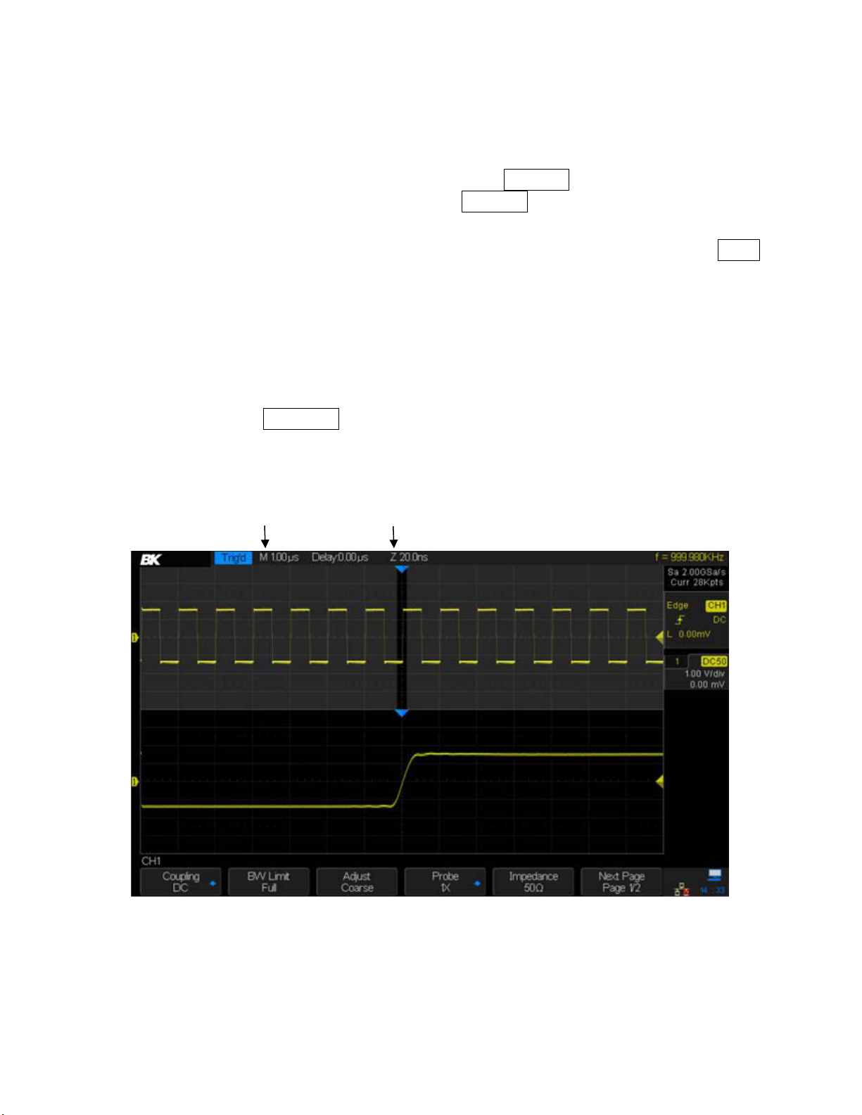
The Zoom Function
Zoom is a horizontally-expanded version of the normal display. You can use Zoom to locate and
horizontally expand part of the normal window for a more detailed (higher-resolution) view of
signals.
Press the HORIZONTAL Scale Knob to turn on the zoom function; press the button again to turn
off the zoom function. When Zoom function is on, the display divides in half. The top half of the
display shows the normal time base window and the bottom half displays the waveform at a
faster sweep speed.
The area of the normal display that is expanded is outlined with a dark box and the rest of the
normal display is gray. The darker area shows the portion of the normal sweep that is expanded
in the lower half of the screen.
Figure 20 – Zoom function
39
Page 41
To change the time base for the Zoom window, turn the Horizontal Scale knob. The Horizontal
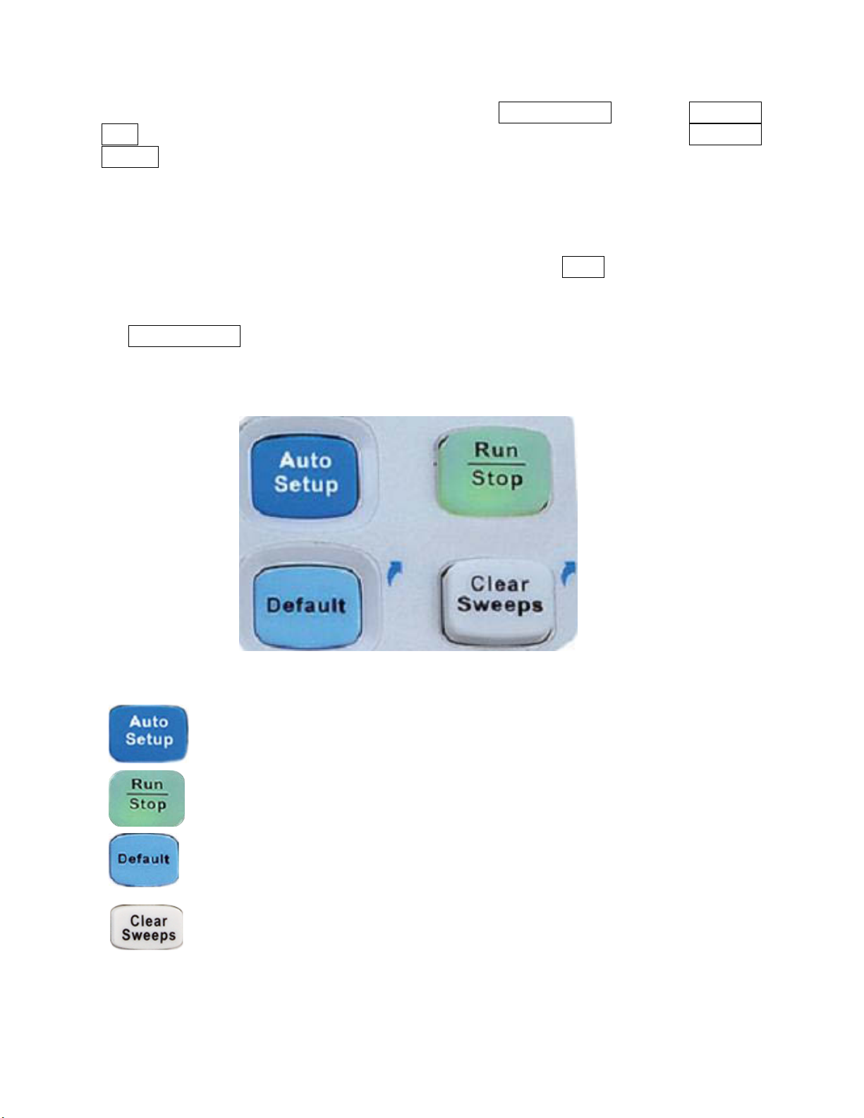
The Auto Setup button automatically adjusts the oscilloscope's settings to get
a stable display.
Use this button to set the state of the instrument to RUN or STOP. In the RUN
state, the button glows yellow; in STOP state, the button glows red.
Press the button to reset the oscilloscope to its default setup state. This is a
useful starting point to let you manually adjust the oscilloscope for your
needs.
This button has two effects. When measurement statistics are being displayed,
pressing this button will set the statistics to zero and start accumulating data
again. When screen persistence is turned on, pressing this button will clear the
persisted waveforms.
Scale knob controls the size of the darker zoom window on the upper waveform. The Horizontal
Position knob sets the position of the zoom window. Negative delay values indicate that a portion
of the waveform before the trigger event is displayed, and positive values indicate a portion of
the waveform after the trigger event.
If the zoomed time/div (prefaced with Z at the top of the screen) is substantially smaller than the
main time/div, you may see significant jitter on things like the edges of fast-rising pulses. You can
get a stable display for making measurements by pressing the Single trigger button. Turn
persistence on to measure jitter.
To change the zoomed time base of the normal window, turn off the Zoom function and adjust
the Horizontal Scale knob.
3.5 Run Control
Figure 21 - Run control buttons
40
Page 42

Decode
Button
Press the Decode button to open the decode menu (Decode is an
optional feature). The 2560 Series supports two 8-bit serial buses for
decoding. Supported serial protocols include I2C, SPI, UART/RS232,
CAN, and LIN.
Digital
Button
Press the Digital button to open the digital menu for the 16-channel
logic analyzer (optional).
Math
Button
Press the Math button to open the Math menu. The operations
include adding, subtracting, multiplying, and dividing two waveforms,
taking the FFT of a waveform, if integrating it, differentiating it, or
taking its square root.
Ref
Button
This button lets you store reference waveforms. A reference
waveform can be compared to an on-screen waveform. Up to four
reference waveforms can be saved.
Ref/Math
Vertical
Position
Knob
Sets the vertical offset of Math or Reference waveforms. Press the
knob to reset the offset to zero.
Ref/Math
Vertical
Scale
Sets the vertical scale of Math or Reference waveforms. During the
modification, the amplitude of the waveform will increase or decrease
and the scale value displayed on the right side of the screen will
Test Equipment Depot - 800.517.8431 - 99 Washington Street Melrose, MA 02176
3.6 Multi-Function Control
TestEquipmentDepot.com
Figure 22 - Multi-function control
41
Page 43

Knob
change accordingly. Push the knob to switch the vertical scale
adjustment modes between Coarse and Fine. In addition, the knob
can be used to change a digital channel.
3.7 Universal Knob
Figure 23 - Universal knob
Adjust the waveform intensity
In non-menu-operation mode, (the menu is hidden or no softkey is actuated by a recent
press), turn this knob to adjust waveform intensity (0% to 100%). Turn clockwise to increase
the brightness and counterclockwise to reduce. You can also press Display/Persist →
Intensity and use the Universal Knob to do adjusting. Adjusting grid brightness (0% to 100%)
and transparency (20% to 80%) are done in a similar fashion.
Universal Knob
When a menu's softkey has been pressed, this knob can be used to select the desired
setting. Press the knob to select the highlighted item. The knob is also used to modify
parameters and to input a file name.
3.8 On-line Help
The oscilloscope has an online help function for its features. Press any button for 2 seconds to
enter the on-line help.
You can change the language the help is displayed in by using the Utility → Language button.
Only Chinese and English are currently supported (the other language choices are for screen
labels).
42
Page 44
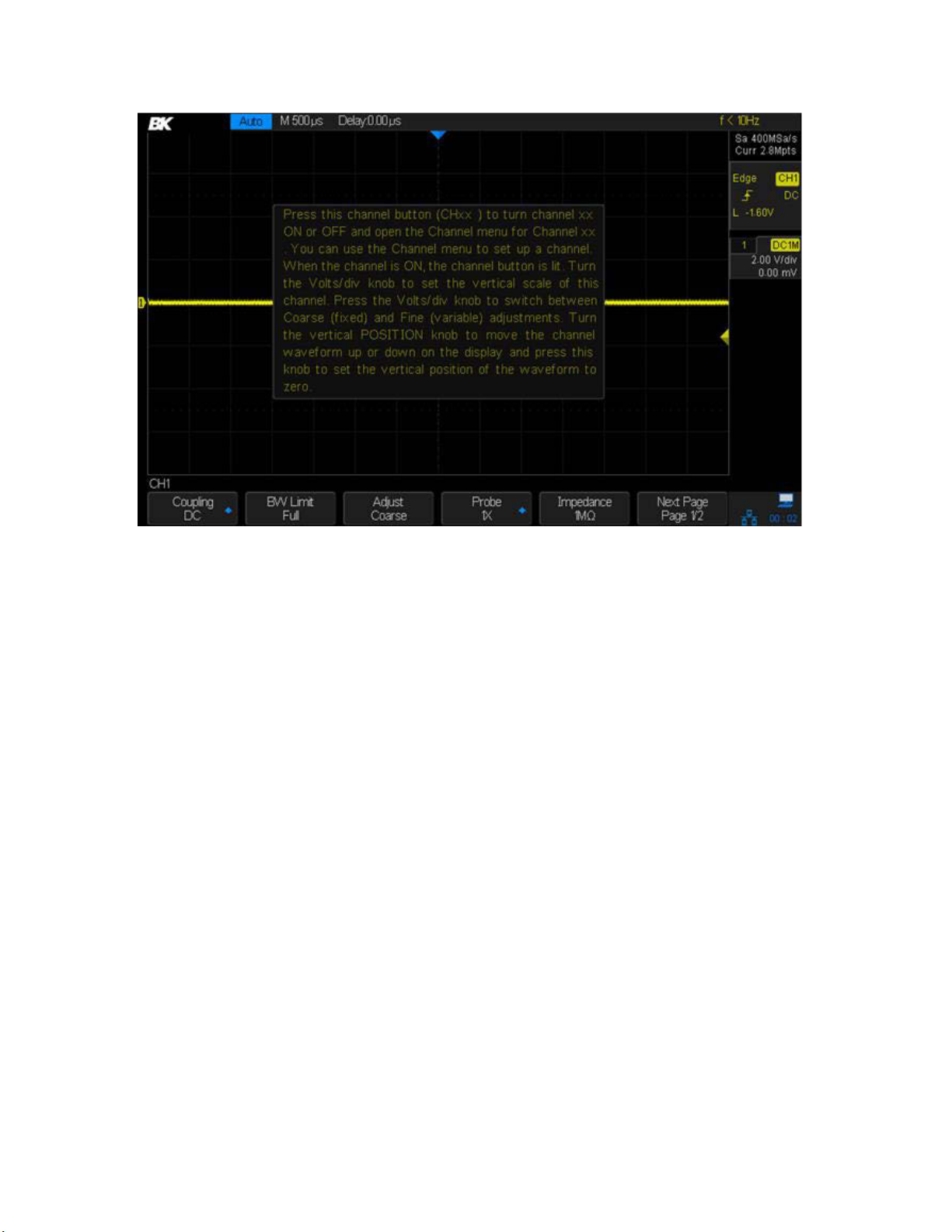
Figure 24 - Help message
43
Page 45

4 Sample System Configuration
This chapter shows how to use the run control and set the sampling system of the oscilloscope.
4.1 Run Control
Press the Run/Stop or Single button on the front panel to run or stop the sampling system of the scope.
When the Run/Stop button is green, the oscilloscope is running (acquiring and storing data
when the trigger conditions are met). To stop acquiring data, press the Run/Stop button.
When stopped, the last acquired waveform is displayed.
When the Run/Stop button is red, data acquisition is stopped. A red "Stop" is displayed next
to the B&K logo in the status line at the top of the display. To start acquiring data, press
Run/Stop.
To capture and display a single acquisition (whether the oscilloscope is running or stopped),
press Single. The Single run control lets you capture single-shot events without subsequent
waveform data overwriting the display. Use Single when you want maximum memory depth
for pan and zoom.
When Single is pressed, the display is cleared and the trigger mode is temporarily set to Normal
to keep the oscilloscope from auto-triggering immediately. The trigger circuitry is armed and the
Single key is illuminated. The oscilloscope will wait until a user-defined trigger condition occurs.
After triggering, the captured waveform is displayed and the oscilloscope is stopped (the
Run/Stop button will be red).
Press Single again to acquire another waveform. You can save the stored waveform to a flash
disk if you wish.
4.2 Overview of Sampling
To understand the sampling and acquisition modes of the oscilloscope, it is helpful to understand
sampling theory, sample rate, and oscilloscope bandwidth.
Sampling Theory
The Nyquist sampling theorem states that for a band-limited signal with a maximum frequency
compliment f
maximum frequency f
The other requirement of the theorem is that the samples be taken at equal intervals.
Sampling Rate
The maximum sampling rate of the oscilloscope is 2 GSa/s. The actual sampling rate of the
oscilloscope is determined by the horizontal scale. Turn the Horizontal Scale knob to adjust the
sampling rate.
, the equally-spaced sampling frequency fS must be greater than twice the
MAX
for the signal to be accurately reconstructed without aliasing.
MAX
f
= fS/2 = Nyquist frequency (fN) = folding frequency
MAX
44
Page 46

The current sampling rate is displayed in the information area at the upper-right corner of the
Pulse disappears
screen.
When the sampling rate is too low, the sampled waveform may contain distortion, aliasing, and
leakage.
1. Waveform Distortion: When the sampling rate is too low, waveform details are lost and the
displayed waveform is different from the actual signal.
Figure 25 - Waveform distortion
2. Waveform Aliasing: When the sampling rate is lower than twice the Nyquist frequency, the
frequency of the waveform reconstructed from the sample data is lower than the actual
signal frequency. The most common aliasing is jitter on a fast edge.
3. Waveform Leakage: When the sampling rate is too low, the waveform reconstructed from
Figure 26 - Waveform aliasing
the sample data does not contain all the actual signal information.
Figure 27 - Waveform leakage
45
Page 47

0 dB
-3dB
fN f
S
Frequency
Test Equipment Depot - 800.517.8431 - 99 Washington Street Melrose, MA 02176
TestEquipmentDepot.com
Oscilloscope Bandwidth and Sample Rate
The bandwidth of an oscilloscope is usually stated as the lowest frequency at which a sine wave's
amplitude is measured as 30% lower than its actual value (this is equivalent to a 3 dB drop in
power because 20log(1/sqrt(2)) is -3).
At the oscilloscope bandwidth, theory says the required sample rate (the Nyquist frequency) is
fS = 2fBW. However, the Nyquist sampling theorem assumes the signal is band-limited. Here, that
means there are no frequency components in the signal above fBW. This is unrealistic in many
practical measurements because it would require a "brick wall" filter:
Attenuation
Figure 28 - Bandwidth and sampling rate
However, digital signals have frequency components above the fundamental frequency (square
waves are made up of sine waves at the fundamental frequency with an infinite number of odd
harmonics), and typically, for 500 MHz bandwidths and below, oscilloscopes have a Gaussian
frequency response.
46
Page 48

Aliased frequency
components
Attenuation
f
S
/4 f
N
f
S
-3dB
Frequency
0dB
Limiting oscilloscope bandwidth (fBW) to ¼ the sample rate (fs/4)
reduces frequency components above the Nyquist frequency (f
N
).
Figure 29 Bandwidth and Nyquist frequency
In practice, an oscilloscope's sampling rate should be four or more times its bandwidth: fS = 4fBW.
This way, there is less aliasing and the aliased frequency components have a greater amount of
attenuation.
4.3 Memory Depth
Memory depth refers to the number of points sampled from the waveform that the oscilloscope
can store in a single trigger sample. It directly reflects the amount of sample memory. There is
separate memory for each interleaved channel set (CH1 and CH2 interleaved, CH3 and CH4
interleaved). The oscilloscope provides up to 140 Mpts memory depth (70 Mpts if two interleaved
channels are being displayed).
To change the memory depth
1. Press the Acquire button on the front panel.
2. Press the Mem Depth softkey.
3. Turn the Universal Knob to select the desired value and press the knob to confirm.
4. Pressing the Mem Depth softkey repeatedly can also select the desired value. The current
memory depth is displayed in upper-right corner of the screen.
The following equation relates memory depth D (in samples), sampling rate R (samples per
second), and waveform length T (seconds):
𝐷 = 𝑅𝑇
47
Page 49

Limiting the oscilloscope bandwidth (fBW) to 1/4 the sample rate will reduce frequencies above
the Nyquist frequency.
4.4 Sampling Mode
The oscilloscope only supports real-time sampling. In this mode, the oscilloscope samples and
directly displays the waveform containing a trigger event. The maximum real-time sample rate
of the oscilloscope is 2 GSa/s.
Press the Run/Stop button to stop the sampling and the oscilloscope will display the last
waveform sample. Use the vertical and horizontal controls to explore the waveform in more
detail.
4.5 Waveform Interpolation Method
With real-time sampling, the oscilloscope acquires a single set of samples in real time. You can
display these samples using dots by pressing Display → Type and choosing Dots. Switch between
the dots and vector display to see how the display methods differ. The vector display method
draws lines connecting the dots; this is called interpolation. Most users seem to prefer an
interpolated waveform, as it coincides with the notion of a continuous function.
There are two interpolation methods provided: x and Sinx/x. The first type connects the dot with
a straight line. Sinx/x interpolation connects the dots with curves, leading to a more accurate
display for real-world signals.
Press the Acquire button and go to page 2 of the ACQUIRE menu. Press the Interpolation button
to select either x or Sinx/x for the interpolation method.
x: Sample points are directly connected using a straight line. This method is
recommended for square waves and pulses to maintain fast rising and falling edges.
Sinx/x: This interpolation method connects the sampled points with curves. When the
sampling rate is 3 to 5 times the bandwidth of the system, Sinx/x interpolation method is
recommended.
48
Page 50
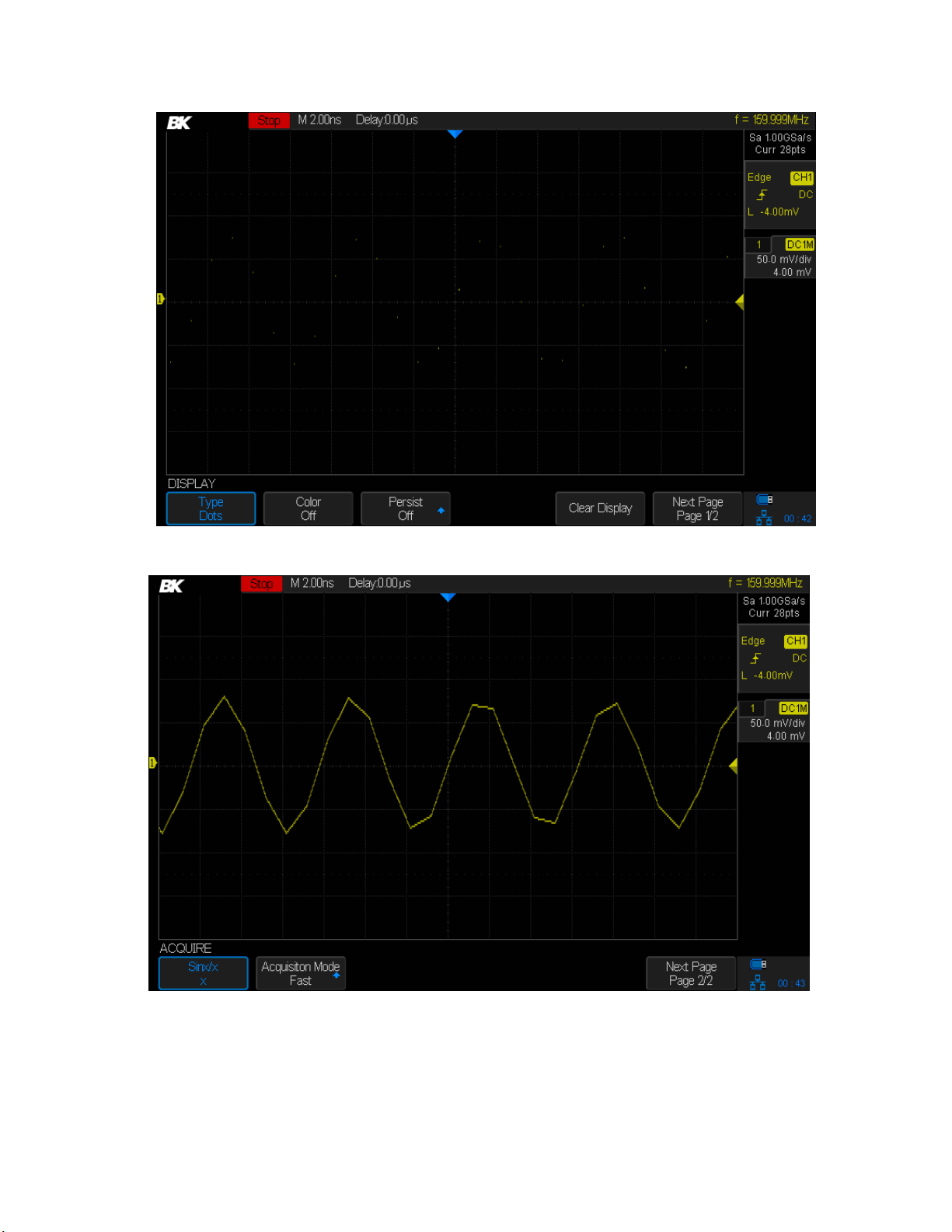
Figure 30 - Display type set to dots
Figure 31 - x interpolation (i.e., connect the dots with lines)
49
Page 51

Figure 32 - Sinx/x interpolation
50
Page 52

Figure 33 - Acquisition, Normal
Test Equipment Depot - 800.517.8431 - 99 Washington Street Melrose, MA 02176
TestEquipmentDepot.com
4.6 Acquisition Mode
The acquisition mode controls how the waveform's points are displayed from sampled points.
The oscilloscope provides the following acquisition modes: Normal, Peak Detect, Average and
Eres.
1. Press the Acquire button on the front panel to enter the ACQUIRE menu.
2. Press the Acquisition softkey and turn the Universal Knob to select the desired acquisition
mode. Push down the knob to confirm.
Normal mode (default)
In this mode, the oscilloscope samples the signal at equal time intervals to reconstruct the
waveform. For the majority of waveforms, normal mode is probably the best choice (you will use
other modes for problematic waveforms). Normal is the default acquisition mode.
Peak Detect
In peak detect mode, the oscilloscope acquires the maximum and minimum values of the signal
within the sample interval to get the envelope of the signal. Signal aliasing is prevented, but the
displayed noise may be larger.
Two common uses for peak detect are to show narrow pules during slow sweeps and show the
envelope of a waveform, which is useful when it has noise on it. Pulses as short as 1 ns can be
seen with peak detect on.
51
Page 53

Figure 34 - Pulse with 0.1% duty cycle, normal mode
Figure 35-Pulse with 0.1% duty cycle, peak detect mode
Average
In this mode, the oscilloscope averages the waveforms from multiple frames to reduce the
random noise of the input signal and improve the vertical resolution.
52
Page 54

When the number of waveform averages is large, the noise will be lower and the vertical
resolution will be better. However, the response time for changes in the signal will be lower
because of the need to capture the extra frames.
The number of frames averaged are 4, 16, 32, 64, 128, 256, 512, and 1024. The default is 16.
To select Average mode, press the Acquire button, press the Acquisition key, and select Average.
Press the Averages key to select the sample size to average by turning the Universal Knob.
Figure 36 - With random noise, normal mode
53
Page 55

Figure 37 - Random noise averaged out
Eres (Enhanced Resolution)
Eres mode uses a digital filter to reduce the random noise on the input signal and generate
smoother waveforms. Eres can be used on both single-shot and repetitive signals and it does not
slow down the waveform update speed. Eres mode limits the oscilloscope's real-time bandwidth
because it acts like a low-pass filter.
54
Page 56

Figure 38 - Eres mode
4.7 Horizontal Format
To choose the horizontal format, press the Acquire button. Pressing the XY softkey toggles between
XY and YT mode. The default mode is YT.
YT: This is the normal viewing mode for the oscilloscope and displays the channel's voltage or
current as a function of time.
XY: This is a scatter plot of channel 1's samples versus channel 2's samples. An example use is in
curve tracing, where a component's current is plotted vertically against the voltage across the
component in the horizontal direction. Look up "Octopus tester" on the web for more details.
XY mode can be used to compare frequency and phase relationships between two periodic
signals that are changing in time. It is used with transducers to display strain versus displacement,
flow versus pressure, voltage versus frequency, etc.
The phase deviation between two sinusoidal signals with the same frequency can be measured
via the Lissajous method and the XY display of the oscilloscope. The figure below shows the
measurement schematic diagram of the phase deviation:
55
Page 57

Figure 39 - Calculating phase difference with Lissajous figure
The phase difference between the two sinusoids is:
𝜃 = 𝑠𝑖𝑛−1(
If the principal axis of the ellipse is within quadrant I and III, the phase difference should be in
quadrant I and IV (between 0 to π/2 or 3π/2 to 2π). If the principal axis of the ellipse is within
quadrant II and IV, the phase difference will be within quadrant II and III (between π/2 to π or π
to 3π/2).
𝐴
⁄ )
𝐵
4.8 Sequence Mode
Sequence mode is used to capture a series of frames. The waveforms are not displayed during
capture, letting the oscilloscope focus its resources on collecting the sample data. This improves
the waveform capture rate. The maximum capture rate is more than 500,000 waveforms/s. An
infrequent event is more likely to be captured using sequence mode.
You set the number of frames to capture (called segments) and the oscilloscope will run until the
specified number of frames has been acquired. The oscilloscope keeps running and filling data
memory in segments for each trigger event until the memory is full. Then you can use the History
button to view the captured data.
Using the Sequence Mode:
1. The HORIZONTAL Format must be set to YT
2. Press the Acquire button on the front panel to enter the ACQUIRE menu.
3. Set the horizontal format to YT by pressing the XY button until it displays Off.
4. Press the Sequence softkey to enter the SEQUENCE menu.
Figure 40: SEQUENCE menu
5. Press the Segments Set softkey and turn the Universal Knob to select the desired value.
56
Page 58
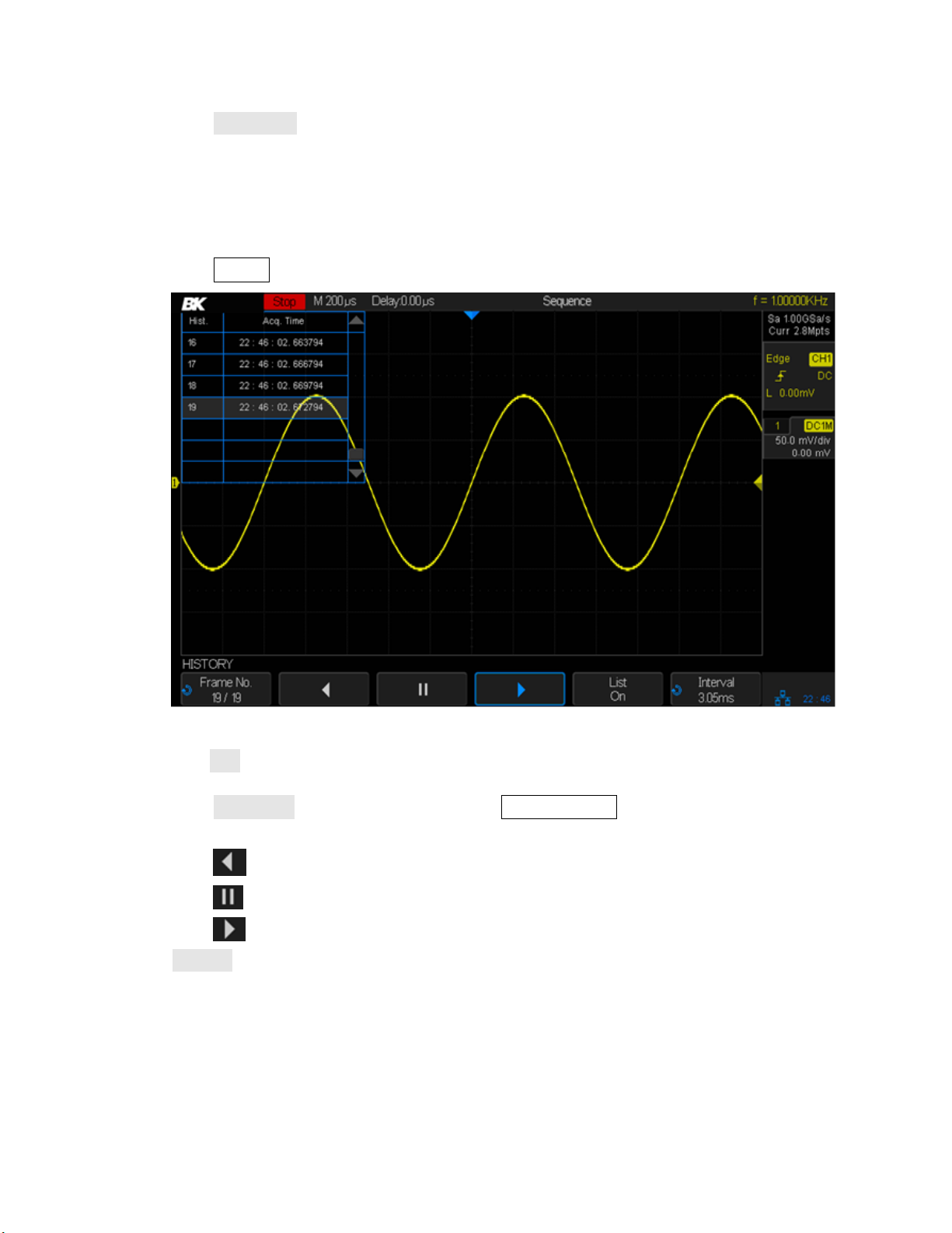
Test Equipment Depot - 800.517.8431 - 99 Washington Street Melrose, MA 02176
TestEquipmentDepot.com
6. Press the Acq. Mode softkey until it displays On.
7. You will see a message at the lower right of the screen saying the segments are being
acquired.
Replaying a sequence of captured waveforms
1. Press the History button to enable the HISTORY menu.
Figure 41 - HISTORY menu
2. Press the List softkey to turn on the list display. The list shows the acquisition time of every
frame and highlights the frame number that is displayed on the screen.
3. Press the Frame No. softkey; and then turn the Universal Knob to select the frame to
display.
4. Press the softkey to replay the waveform from the current frame to the first frame.
5. Press the softkey to pause the replay.
6. Press the softkey to replay the waveform from the current frame to the last frame.
7. The Interval softkey sets the time between frames. You can view the sequentially-captured
waveforms like a movie and quickly find unusual behavior.
57
Page 59

5 Trigger
Setup: Press this button to open the trigger menu. This menu lets you control
how the oscilloscope's capture system decides when to capture a waveform.
This oscilloscope provides a variety of trigger types: Edge, Slope, Pulse, Video,
Window, Interval, Dropout, Runt, Pattern and Serial Bus
(I2C/SPI/UART/RS232/CAN/LIN).
Auto: Auto triggering is a triggering method that always lets you see a trace on
the screen. If the normal triggering scheme does not trigger after a certain time,
the oscilloscope generates a trigger.
Normal: Normal triggering has the oscilloscope trigger (i.e., capture the
waveform into memory and display it) when the trigger conditions are met. After
the waveform is displayed, the oscilloscope arms the trigger and waits for
another trigger event and displays the next waveform when triggered.
Single: This is the same as normal triggering except the trigger is disabled after
the first waveform is captured. This allows you to see the details of the waveform
that caused the trigger. It is useful for capturing transient events that don't
repeat.
Trigger Level Knob: Sets the voltage or current level that the oscilloscope will
trigger at. This trigger level is displayed in the upper right portion of the display.
Press the knob to set the trigger level to 50% of waveform's amplitude.
Figure 42 - Trigger
5.1 Overview of triggering
The trigger determines when the oscilloscope starts to acquire data and display a waveform.
When a trigger is set up properly, the oscilloscope converts unstable displays or blank screens
into meaningful waveforms
58
Page 60

Note: the 2560 Series oscilloscopes allow the use of either voltage or current units for waveform
Softkey
Description
Multiple cycles
Shows multiple cycles. This is the default behavior.
One cycle
Shows one cycle of the waveform.
Rising edge
Puts a rising edge at the center of the screen by changing the
trigger slope to positive.
Falling edge
Puts a falling edge at the center of the screen by changing the
trigger slope to negative.
Restore previous settings
Go back to your previous settings. This acts like an undo button.
Noisy sine wave
Changes to averaging mode with a sample size of 16 to reduce
noise.
measurements. The remainder of this chapter will refer to just voltages, but it applies to current
levels, too.
5.2 Auto Setup
The oscilloscope automatically identifies the waveform type, trigger level, and scales to produce
a usable display of the input signal.
Press the Auto Setup button to perform the function and the following softkeys will be available.
If the waveform is out of the Auto Setup's range, a dialog window will is displayed explaining that
Auto Setup did not work.
5.3 Setting the Trigger
Digital oscilloscopes capture the waveform continuously, but will not display the captured
waveform unless the oscilloscope is triggered. A stable display needs a stable trigger. The
triggering circuitry generates a trigger event when the logical trigger conditions are satisfied by
the waveform.
Here is a schematic diagram of the acquisition memory. The position of the trigger event in time
is defined to be the zero-time location. Waveform samples before the trigger event are in the
pre-trigger buffer and samples after the trigger event are in the post-trigger buffer. By default,
the trigger event is shown at the center of the screen, but turning the horizontal position knob
lets you put other portions of the buffer in the center of the screen.
59
Page 61

Choosing the right trigger mode and setting it up correctly can take some practice and it is best
Figure 43 - Acquisition Memory Schematic
done if you know something about the signal you are trying to capture. The oscilloscope provides
a variety of triggering types and logical conditions for generating a trigger event, such as Edge,
Slope, Pulse, Video, Window, Interval, Dropout, Runt, Pattern and Serial triggering. These
triggering types will be discussed in the following sections.
5.4 Trigger Source
The trigger source is the signal that will be compared to the logical conditions you set to generate
a trigger event. The most common trigger source is the signal on one of the analog input channels,
but the EXT BNC connector on the front panel can be used to trigger on an external signal. If you
are looking at waveforms that are derived from the AC line power, you'll probably want to use
the AC line as the trigger source. For example, to measure the 120 Hz ripple in a voltage regulator
circuit, you'd want to trigger on the 60 Hz AC line for a stable signal.
Press the Setup button in the Trigger section on the front panel to enter the TRIGGER menu.
Press the Source softkey and then turn the Universal Knob to select the desired trigger source.
The current trigger source is displayed at the upper right corner of the screen.
The edge trigger type allows triggering from the analog channels, an external signal on the EXT
input terminal, or the AC line. The remaining triggering types use only the analog channels as
their source.
If you select the Serial trigger type, the Source softkey changes to the Protocol softkey.
For the analog and external triggers, the trigger level can be set from -4 to 4 screen divisions.
5.5 Trigger Mode
The three trigger modes are Auto, Normal and Single.
After the oscilloscope begins to capture data, the oscilloscope operates by first filling the pre-
trigger buffer. The oscilloscope starts searching for a trigger after the pre-trigger buffer is filled
and data continues to flow through this buffer while it searches for the trigger. While searching
for the trigger, the oscilloscope overflows the pre-trigger buffer and the first data put into the
buffer is pushed out.
60
Page 62

When a trigger is found, the pre-trigger buffer retains the events that occurred just before the
Trigger Level
Negative Slope
Positive Slope
Trigger Point
Input Signal
trigger. Then, the oscilloscope fills the post-trigger buffer and displays both buffers on the screen.
Press the Auto, Normal or the Single button on the front panel to select the desired trigger mode.
The lighted button indicates the current trigger mode.
Auto: The oscilloscope waits for the trigger logical conditions to be satisfied, but if the trigger
conditions are not satisfied after a period of time, the oscilloscope generates an internal trigger
event, causing the trace to be displayed. Auto mode is useful for measuring DC voltages and
unknown signals. Once a signal is displayed, you may want to change to Normal mode.
Normal: The oscilloscope waits for the trigger logical conditions to be satisfied; when they are, a
trigger event is generated and the trace is displayed. The triggering circuitry re-arms itself and
again waits for the trigger logical conditions to be satisfied. Use normal triggering when you do
not want to see the horizontal line when the input is DC or there's no signal.
Single: This mode is the same as the normal mode, except the oscilloscope is put into the Stopped
state after the trigger event has occurred. The single trigger mode is commonly used to capture
infrequent transient events that do not repeat in time. One example of use is to capture the
contact bounce of a mechanical switch.
5.6 Trigger Level
The level and slope define the trigger point for an edge trigger. The trigger level can be adjusted
for an analog channel or external signal by turning the Trigger Level knob.
Push the Trigger Level knob to set the level to the middle of the waveform. If AC coupling is used,
pushing the Trigger Level knob sets the trigger level to approximately 0 V. The position of the
trigger level for the analog channel is indicated by the trigger level icon (if the channel is on)
on the right side of the display. The value of the analog channel trigger level is displayed in the
upper-right corner of the display. The color of the icon tells you which channel is providing the
trigger signal (more detailed information is in the trigger box in the right column of the screen.
Figure 44 - Trigger level for an edge trigger
61
Page 63

Note: Trigger coupling is different from channel coupling.
Test Equipment Depot - 800.517.8431 - 99 Washington Street Melrose, MA 02176
TestEquipmentDepot.com
5.7 Trigger Coupling
Press the Setup button on the front panel to enter the TRIGGER menu, then press the Coupling
softkey and turn the Universal Knob or press the Coupling softkey continually to select one of
the following trigger coupling modes:
• DC: Allows both DC and AC components into the trigger path.
• AC: Blocks the DC components and attenuates signals lower than 8 Hz. Use AC coupling
to get a stable edge trigger when your waveform has a DC offset.
• LF Reject: Blocks the DC components and rejects the low frequency components below
900 kHz. Use LF Reject coupling to get a stable edge trigger when your waveform has low
frequency noise, power line harmonics, etc.
• HF Reject: Reject high frequency components higher 500 kHz.
5.8 Trigger Hold Off
Trigger Hold Off can be used to stabilize the triggering of complex waveforms such as series of
pulses. Hold off time is the amount of time that the oscilloscope waits after a trigger event
before re-arming the trigger circuitry. The oscilloscope will not trigger until the hold off time
expires.
Use the Hold Off option to trigger on repetitive waveforms that have multiple edges (or other
events) between waveform repetitions. You can also use the Trigger Hold Off to trigger on the
first edge of a burst when you know the minimum time between bursts.
For example, to get a stable trigger on the repetitive pulse burst shown below, set the hold off
time to be greater than 200 ns but less than 600 ns.
Figure 45 - Trigger hold off
To set the Hold Off:
1. Press the Run/Stop button to stop waveform capture, and then use the Horizontal Position
knob and the Horizontal Scale knob to find where the waveform repeats.
2. Measure this time using cursors or using the screen's graticule.
62
Page 64

3. Press the Setup button on the front panel to enter the TRIGGER menu. The trigger type must
Note: Adjusting the time scale and horizontal position will not affect the hold off time.
be Edge.
4. Press the Holdoff Close soft key until it reads Holdoff Time.
5. Turn the Universal Knob to set the desired hold off time.
6. When you no longer need a holdoff time, press the Holdoff Time soft key until it reads Holdoff
Close.
5.9 Noise Rejection
Noise Reject adds additional hysteresis to the trigger circuitry. By increasing the trigger hysteresis
band, you reduce the possibility of triggering on noise. This decreases the trigger sensitivity so a
slightly larger signal is required to trigger the oscilloscope.
Press the Setup button on the front panel, and then press the Noise Reject softkey to turn noise
rejection on or off.
If the signal is noisy, you can set the oscilloscope to reduce the noise in the trigger path and on
the displayed waveform. To reduce noise from the trigger path:
1. Connect a signal to the oscilloscope and obtain a stable display.
2. Press the Setup button.
3. Press the Coupling softkey and choose LF Reject or HF Reject. Alternatively, you can press
the Noise Reject softkey until it says On.
4. Optional: Press the Acquisition button and choose the Average option to reduce random
vertical noise on the displayed waveform.
63
Page 65

Figure 46 - Turn off noise reject
Figure 47 - Turn on noise reject
5.10 Trigger Types
The oscilloscope provides multiple advanced trigger functions, including various serial bus
triggers.
64
Page 66

Edge Trigger
An edge trigger's logical condition is met when the waveform passes through a set voltage level
while increasing (positive slope) or passes through a set voltage level while decreasing (negative
slope).
In the following diagram, the trigger event will occur when the slope is positive at the left-most
trigger point. Conversely, the trigger event will occur at the right-most trigger point for a negative
slope.
Figure 48 - Edge trigger
To set the Edge Trigger
1. Press the Setup button on the front panel to enter the trigger menu.
2. Press the Type softkey. Turn the Universal Knob to highlight Edge and push the knob to select.
3. Press the Source softkey. Turn the Universal Knob to select one of the analog channels, EXT,
EXT/5 or AC Line as the trigger source.
4. Press the Slope softkey. Turn the Universal Knob to select the desired trigger edge (Rising,
Falling or Alter), and then press the knob to confirm. The current trigger slope is displayed at
the upper right corner of the screen. Alter is an alternating trigger that will trigger on
alternate rising and falling slopes.
5. Adjust the Trigger Level knob to get stable trigger.
65
Page 67

Note: Pressing the Auto Setup button will set the trigger type to Edge and the slope to rising.
Figure 49 - Edge trigger
Slope Trigger
The slope trigger's logical condition is a transition between two voltage levels when the time of
the transition meets a condition. The transition time can be greater than or less than a specified
number, within a specified range of times, or outside of a specified range of times. The slope of
the waveform can be set to rising or falling. The following figure shows a positive slope time,
which is defined as the time difference between the two crossing points of trigger levels A and B
on the positive slope of the waveform.
Figure 50 - Positive slope time
To set the Slope Trigger:
1. Press the Setup button to enter the TRIGGER menu.
2. Press the Type softkey. Turn the Universal Knob to select Slope and push the knob to confirm.
66
Page 68

3. Press the Source softkey. Turn the Universal Knob to select the analog channel you wish to
use as the trigger source.
4. Press the Slope softkey to choose between rising and falling slope. The current trigger slope
is displayed at the upper right corner of the screen.
Figure 51 - Slope trigger
5. Press the Limit Range softkey.
6. Press the softkey to the immediate right of the Limit Range softkey to adjust the slope time(s).
7. Turn the Universal Knob to select the desired slope condition and push the knob to confirm.
< (Less than a time value): Trigger when the slope time of the input signal is less than the
specified time.
> (Greater than a time value): Trigger when the slope time of the input signal is greater
than the specified time value.
[--,--] (Within a range of time values): Trigger when the slope time of the input signal is
greater than the specified lower limit and less than the specified upper limit.
--][-- (Outside a range of time values): Trigger when the slope time of the input signal is
greater than the specified upper limit or less than the specified lower limit.
8. Press the Next Page softkey and press Lower Upper softkey to set the Lower and Upper
trigger levels.
9. Turn the Trigger Level knob to adjust the position. The trigger level values are displayed at
the upper right corner of the screen.
67
Page 69

Note: The lower trigger level cannot be larger than the upper trigger level. In the trigger state
message box, L1 means the upper trigger lever while L2 means the lower trigger level.
Positive Pulse Width
Negative Pulse Width
Trigger Level
Figure 52 - Pulse Trigger
Test Equipment Depot - 800.517.8431 - 99 Washington Street Melrose, MA 02176
TestEquipmentDepot.com
Pulse Trigger
This trigger is used to trigger on a positive or negative pulse with a specified width.
To set the Pulse Trigger:
1. Press the Setup button to enter the TRIGGER menu.
2. Press the Type softkey. Turn the Universal Knob to select Pulse and push the knob to confirm.
3. Press the Source softkey. Turn the Universal Knob to choose which analog channel to use for
the trigger source.
4. Turn the Trigger Level Knob to adjust the trigger level. The pulse width will be measured at
this voltage on the waveform.
5. Press the Polarity softkey to trigger on a Positive or Negative pulse. The current trigger
polarity is displayed at the upper right corner of the screen.
6. Press the Limit Range softkey. Turn the Universal Knob to select the desired condition.
< (Less than specified time): Trigger when the measured pulse width is less than the
specified time.
For example, for a positive pulse, if you set the pulse width < 100 ns, the oscilloscope will trigger
on the following waveform:
68
Page 70

> (Greater than specified time): Trigger when the measured pulse width is greater than
the specified time.
For example, for a positive pulse, if you set the pulse width >100 ns, the oscilloscope will trigger
on the following waveform
[--,--] (Within a range of specified times): Trigger when the pulse width is between the
lower and upper specified times.
For example, for a positive pulse, if you set the pulse width) between 100 ns and 300 ns, the
oscilloscope will trigger on the following waveform
--][-- (Outside a range of specified times): Trigger when the pulse width is greater than
the upper limit or lower than the lower limit. This is the logical complement of the
previous triggering interval.
Figure 53 - Pulse trigger
69
Page 71

Video Trigger
Standard
Type
Sync Pulse
NTSC
Interlaced
Bi-level
PAL
Interlaced
Bi-level
HDTV 720P/50
Progressive
Tri-level
HDTV 720P/60
Progressive
Tri-level
HDTV 1080P/50
Progressive
Tri-level
HDTV 1080P/60
Progressive
Tri-level
HDTV 1080i/50
Interlaced
Tri-level
HDTV 1080i/60
Interlaced
Tri-level
Custom
Softkey
Frame rate 25 Hz, 30 Hz,
50 Hz, 60 Hz
Of Lines
300 - 2000
Of Fields
1, 2, 4, or 8
Interlace
1:1, 2:1, 4:1, 8:1
Trigger Position
Line
Field
(line value)/1
1
(line value)/2
2
Video triggering is used to get stable displays of analog video signals and allows you to view any
portion of a video frame. For NTSC (National Television Standards Committee), PAL (Phase
Alternating Line), 1080i (50 Hz or 60 Hz), or custom video signals, you can trigger on a selected
line or field. For the HDTV (High Definition Television) 720p and 1080p signals (either 50 or 60
Hz), you can trigger on a selected line.
To set the Video Trigger:
1. Press the Setup button on the front panel to enter the TRIGGER menu.
2. Press the Type softkey. Turn the Universal Knob to select Video and push the knob to confirm.
3. Press the Source softkey. Turn the Universal Knob to select an analog channel as the trigger
source.
4. Note the Trigger Level knob does not change the trigger level because the trigger level is
automatically set to the sync pulse.
5. Press the Standard softkey to select the desired video standard. The oscilloscope supports
the following video standards:
The following table shows the parameters of the Custom video trigger:
70
Page 72

(line value)/3
3
(line value)/4
4
(line value)/5
5
(line value)/6
6
(line value)/7
7
(line value)/8
8
Of Lines
Of Fields
Interlace
Trigger Line
Trigger Field
800 1 1:1
800
1
800
1, 2, 4 or 8
2:1
400
1, 1-2, 1-4, 1-8
800
1, 2, 4 or 8
4:1
200
1, 1-2, 1-4, 1-8
800
1, 2, 4 or 8
8:1
100
1, 1-2, 1-4, 1-8
Standard
Field 1
Field 2
NTSC
1 to 262
1 to 263
PAL
1 to 312
1 to 313
HDTV 720P/50, HDTV 720P/60
1 to 750
HDTV 1080P/50, HDTV 1080P/60
1 to 1125
HDTV 1080iP/50, HDTV 1080i/60
1 to 562
1 to 563
The table below takes Of Lines as 800 as an example to explain the relation between Of Lines, Of
Fields, Interlace, Trigger Line and Trigger Field.
6. Press the Sync softkey to select Any or Select trigger mode.
Any: Trigger on any of the horizontal sync pulses.
Select: Trigger on the line and field you have selected. Press the Line or Field softkey;
then turn the Universal Knob to set the value.
The following table lists the line numbers per field for each video standard:
The following exercises will help familiarize you with video triggering.
Trigger on a Specific Line of Video
Video triggering requires greater than 1/2 division of sync amplitude with any analog channel as
the trigger source.
The example below sets the oscilloscope to trigger on field 2, line 124 using the NTSC video
standard.
1. Press the Setup button on the front panel to enter the TRIGGER menu.
71
Page 73

2. Press the Type softkey. Use the Universal Knob to select Video and push the knob to confirm.
3. Press the Source softkey. Turn the Universal Knob to select the channel that has the video
signal as the trigger source and press the knob to confirm.
4. Press the Standard softkey. Turn the Universal Knob to select NTSC and press the knob to
confirm.
5. Press the Sync softkey and set the option to Select. Press the Line softkey and turn the
Universal Knob to select 022 and push the knob to confirm. Press the Field softkey and turn
the Universal Knob to select 1 and push the knob to confirm
Figure 54 - Video Trigger
To Use the Custom Video Trigger
Custom video trigger supports frame rates of 25 Hz, 30 Hz, 50 Hz and 60 Hz. The line range
available is from 300 to 2000. The steps below show you how to set custom trigger.
1. Press the Setup button on the front panel to enter the TRIGGER menu.
2. Press the Type softkey. Use the Universal Knob to select Video and push the knob to confirm.
3. Press the Source softkey. Turn the Universal Knob to select the analog channel that has the
video signal as the trigger source and push the knob to confirm.
4. Press the Standard softkey. Turn the Universal Knob to select Custom and push the knob to
confirm.
5. Press the Setting softkey to enter the custom setting function menu. Press the Interlace
softkey. Turn the Universal Knob to select the desired value.
6. Press the Of Field softkey. Turn the Universal Knob to select the desired value.
72
Page 74

7. Press the Sync softkey to enter the TRIG ON menu to set the line and field.
Press the Type softkey to select Any.
If the Type option is set to Select, press the Line softkey; turn the Universal Knob to select
the desired value.
Press the Field softkey. Turn the Universal Knob to select the desired value.
Window Trigger
The window trigger provides two trigger voltage levels, high and low. The oscilloscope triggers
when the input signal enters or exits the defined voltage window.
There are two kinds of window types: Absolute and Relative. They have different trigger level
adjustment methods.
Absolute Window Trigger: The lower and the upper trigger levels can be adjusted via the
Level knob.
Relative Window Trigger: Adjust the Center value to set the window center. Adjust the
Delta value to set the window height. The lower and the upper trigger levels will move
together.
Figure 55 - Window trigger
If the lower and the upper trigger levels are both within the waveform amplitude range, the
oscilloscope will trigger on both rising and falling edges. This will display two traces on the
screen.
If the upper trigger level is within the waveform amplitude range while the lower trigger level
is outside of the waveform's amplitude range, the oscilloscope will trigger on the rising edge
only.
If the lower trigger level is within the waveform amplitude range while the upper trigger level
is outside of the waveform's amplitude range, the oscilloscope will trigger on the falling edge
only.
Setting Window Trigger via Absolute window type:
1. Press the Setup button on the front panel to enter the TRIGGER menu.
2. Press the Type softkey. Use the Universal Knob to select Window and press the knob to
confirm.
Test Equipment Depot - 800.517.8431 - 99 Washington Street Melrose, MA 02176
TestEquipmentDepot.com
73
Page 75

3. Press the Source softkey. Turn the Universal Knob to select one of the analog channels as the
trigger source.
4. Press the Window Type softkey to select Absolute.
5. Press the Lower Upper softkey to select the Lower or Upper trigger level. Turn the Level knob
to adjust the position. The trigger level values are displayed at the upper right corner of the
screen. Note the two left-facing pre-trigger level indicators on the right side of the screen.
The Lower trigger level cannot be located higher than the Upper trigger level. In the trigger
state message box, L1 means the upper trigger level while L2 means the lower trigger level.
Figure 56 - Absolute window trigger
Setting Window Trigger via Relative window type:
1. Press the Setup button on the front panel to enter the TRIGGER menu.
2. Press the Type softkey. Use the Universal Knob to select Window and push the knob to
confirm.
3. Press the Source softkey. Turn the Universal Knob to select one of the analog channels as the
trigger source.
4. Press the Window Type softkey to select Relative.
5. Press the CenterDelta softkey to select Center or Delta trigger level mode.
6. Then turn the Level knob to adjust the position. The Center and Delta values are displayed at
the upper right corner of the screen.
In the trigger state message box, C means Center, the center value of the lower and upper
trigger levels. D means Delta, half the difference between the upper and lower levels.
74
Page 76

Figure 57 - Relative window trigger
Trigger
Trigger
Interval Trigger
This trigger should be used when the time difference between neighboring rising or falling edges
meets the one of the time limit conditions (<, >, [--,--], --][--).
Figure 58 - Interval trigger
Setting Interval Trigger:
1. Press the Setup button to enter the TRIGGER menu.
2. Press the Type softkey. Use the Universal Knob to select Interval and push the knob to
confirm.
3. Press the Source softkey and turn the Universal Knob to select one of the analog channels as
the trigger source.
4. Press the Slope softkey to select rising or falling edge.
Press the LimitRange softkey. Turn the Universal Knob to select desired condition:
< (less than a time value): trigger when the positive or negative pulse time of the input
signal is less than the specified time value.
75
Page 77
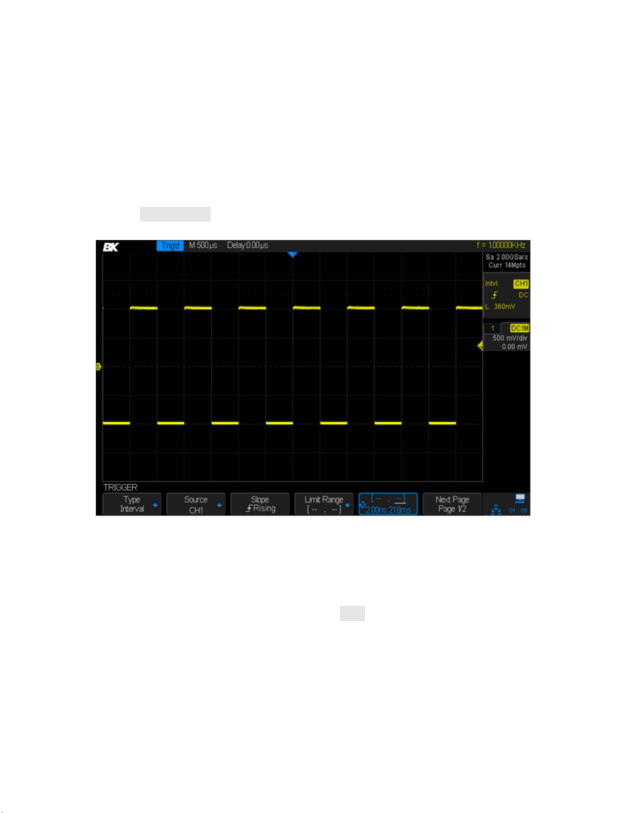
> (greater than a time value): trigger when the positive or negative pulse time of the
input signal is greater than the specified time value.
[--,--] (within a range of time value): trigger when the positive or negative pulse time of
the input signal is greater than the specified lower limit of time and less than the specified
upper limit of time value.
--][-- (outside a range of time value): trigger when the positive or negative pulse time of
the input signal is greater than the specified upper limit of time and less than the
specified lower limit of time value.
5. Press the Time Setting softkey (<, >, [--,--], --][--), turn the Universal Knob to select the
desired value.
Figure 59 - Interval trigger
DropOut Trigger
There are two types of DropOut triggers: edge and state. The oscilloscope will trigger when a
signal edge disappears for longer than a specified time. For example, if you had the oscilloscope
monitoring a digital system's clock, you could set the Time value to slightly longer than the clock
period. The oscilloscope would then trigger on a missing clock pulse.
Edge
Trigger when the time interval (△T) from when the rising edge (or falling edge) of the input signal
passes through the trigger level to when the next rising edge (or falling edge) passes through the
trigger level is greater than the timeout time set, as shown in the figure below.
76
Page 78
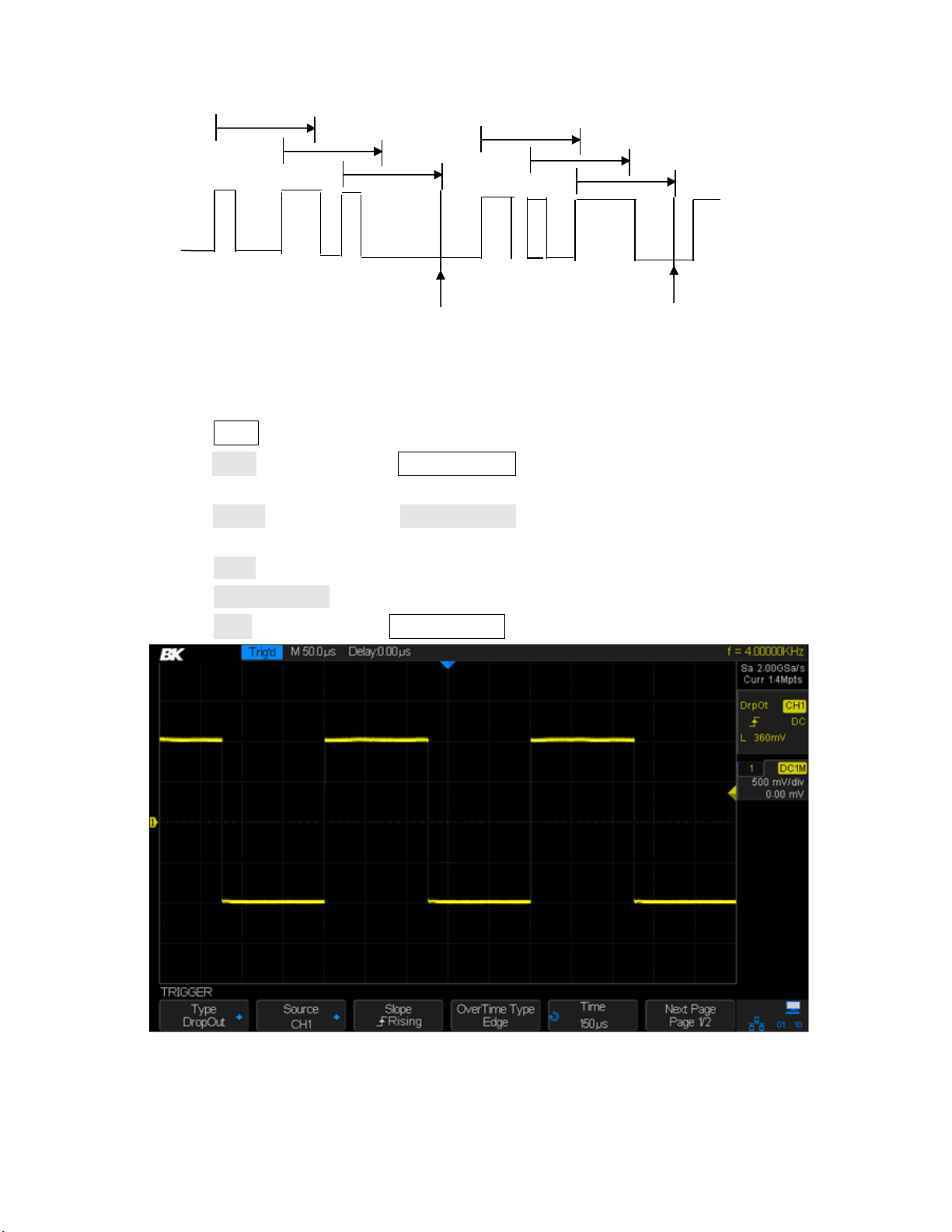
Setting Edge DropOut Trigger
Figure 60 - Edge dropout trigger
Trigger
Trigger
1. Press the Setup button to enter the TRIGGER menu.
2. Press the Type softkey. Use the Universal Knob to select Dropout and push the knob to
confirm.
3. Press the Source softkey. Turn the Universal Knob to select one of the analog channels as the
trigger source. The current trigger source is displayed at the upper right corner of the screen.
4. Press the Slope softkey to select the rising or falling edge.
5. Press the OverTime Type softkey to select Edge.
6. Press the Time softkey. Turn the Universal Knob to select the desired value.
Figure 61 - Edge DropOut trigger
77
Page 79

Trigger when the time interval (△T) from when the rising or falling edge of the input signal passes
Figure 62 - State trigger
Trigger
Trigger
through the trigger level to when the next edge of opposite slope passes through the trigger level
is greater than the timeout time set, as shown in the figure below.
An example of use would be a digital system clock where an isolated pulse gets stretched in time.
Setting the trigger value to slightly more than half the clock's period could find such stretched
pulses.
Setting State DropOut trigger
1. Press the Setup button to enter the TRIGGER menu.
2. Press the Type softkey. Turn the Universal Knob to select DropOut and push the knob to
confirm.
3. Press the Source softkey. Turn the Universal Knob to select an analog channel as the trigger
source.
4. Press the Slope softkey to select rising or falling edge.
5. Press the OverTime Type softkey to select State.
6. Press the Time softkey. Turn the Universal Knob to select the desired value.
Test Equipment Depot - 800.517.8431 - 99 Washington Street Melrose, MA 02176
TestEquipmentDepot.com
78
Page 80

Figure 63 - State DropOut trigger
Low Level
High Level
Positive runt pulse
Negative runt pulse
Figure 64 – Runt Trigger Description
Runt Trigger
The Runt trigger looks for pulses that cross one threshold but not another as shown in the picture
below.
Triggering will occur when
• A positive-going pulse crosses a lower threshold but not an upper threshold.
• A negative-going pulse crosses an upper threshold but not a lower threshold.
To trigger on a runt pulse
1. Press the Setup button to enter the TRIGGER menu.
2. Press the Type softkey. Turn the Universal Knob to select Runt and push the knob to confirm.
79
Page 81

3. Press the Source softkey. Turn the Universal Knob to select an analog channel as the trigger
source.
4. Press the Polarity softkey to select a positive or negative pulse to trigger on.
5. Press the LimitRange softkey. Turn the Universal Knob to select the desired condition (<, >,
[--,--] or --][--).
To adjust the time setting, press the softkey immediately to the right of the Limit Range softkey.
Enter a time by turning the Universal Knob to select the desired value.
Figure 65 - Time setting runt trigger
6. Press the Next Page softkey to enter the second page of the TRIGGER menu. Press the Lower
Upper softkey to select Lower or Upper trigger level. Turn the Universal Knob to set the
position.
80
Page 82

Figure 66 - Runt trigger
Pattern Trigger
The Pattern trigger identifies a trigger condition by looking for a specified pattern. The pattern
trigger can be expanded to incorporate delays similar to other triggers. Pattern durations are
evaluated using a timer. The timer starts on the last edge that makes the pattern “true”. Potential
triggers occur on the first edge that makes the pattern false, provided that the time qualifier
criterion has been met. The oscilloscope provides 4 patterns: logical AND, OR, NAND and NOR
combination of the channels. Each channel can set to low, high or invalid.
81
Page 83

Figure 67 - Pattern Trigger
To set pattern trigger
1. Press the Setup button to enter the TRIGGER menu.
2. Press the Type softkey. Turn the Universal Knob to select Pattern and then push the knob to
confirm.
3. Press the Source softkey to select each channel and press the softkey to the right to select
Don’t Care, High or Low for that channel.
Low sets the pattern to low on the selected channel. A low is a voltage level that is less
than the channel's trigger level or threshold level.
High sets the pattern to high on the selected channel. A high is a voltage level that is
greater than the channel's trigger level or threshold level.
Don’t Care sets the pattern to don't care on the selected channel. Any channel set to
don't care is ignored and is not used as part of the pattern.
However, if all channels in the pattern are set to Don't Care, the oscilloscope will not trigger.
Adjust the trigger level for the selected analog channel by turning the trigger Level knob. An
Invalid channel doesn’t need its trigger level set.
4. Press the Next Page softkey to enter the second page of the pattern trigger menu.
5. Press the Logic softkey and turn the Universal Knob to select the desired logic combination
AND, OR, NAND or NOR.
6. Press the Hold Off Close softkey to turn on the Hold Off function and turn the Universal Knob
to select the desired value.
82
Page 84

Figure 68 - Pattern trigger
Serial Trigger
I2C Triggering
After the oscilloscope has been set up to capture I2C signals, you can trigger on a stop/start
condition, a restart, a missing acknowledge, an EEPROM data read, a read/write frame with a
specific device address and data value, or on a data length.
1. Press the Setup button on the front panel to enter trigger menu.
2. Press the Type softkey. Turn the Universal Knob to select Serial and press the Protocol softkey
to select I2C.
3. Press the Signal softkey to configure the channels to be either SCA or SCL and their logic
voltage threshold levels.
4. Press the softkey and press the Trigger Setting softkey, press the Condition Softkey,
and turn the Universal Knob to select the trigger:
83
Test Equipment Depot - 800.517.8431 - 99 Washington Street Melrose, MA 02176
TestEquipmentDepot.com
Page 85

Start - The oscilloscope triggers when SDA transitions from high to low while the SCL
clock is high. For triggering purposes (including frame triggers), a restart is treated as a
start condition.
Stop - The oscilloscope triggers when data (SDA) transitions from low to high while the
clock (SCL) is high.
Figure 69 – Start vs stop condition
Restart - The oscilloscope triggers when another start condition occurs before a Stop
Condition.
No Ack -The oscilloscope triggers when SDA is high during any Ack SCL clock bit.
EEPROM -The trigger looks for the EEPROM control byte value 1010xxx on the SDA line,
followed by a Read bit and an Ack bit. It then looks for the data value and qualifier set by
the Limit Range softkey and the Data1 softkey. When this event occurs, the oscilloscope
will trigger on the clock edge for the Ack bit after the data byte. This data byte does not
need to occur directly after the control byte.
Figure 70 - EEPROM trigger
To set the oscilloscope to trigger on an EEPROM Data Read condition:
a) Press the Limit Range softkey to set the oscilloscope to trigger when the data is
= (equal to), < (less than), or > (greater than) the data value set in the Data1 softkey.
84
Page 86

The oscilloscope will trigger on the clock edge for the Ack bit after the trigger event
is found. This data byte does not need to occur directly after the control byte. The
oscilloscope will trigger on any data byte that meets the criteria defined by the Byte
Length and Data1 softkeys during a current address read, a random read, or a
sequential read cycle.
7-bit Address & Data Condition - The oscilloscope triggers on a read or write frame in 7-
bit addressing mode on the 17th or the 26th clock edge if all bits in the pattern match.
For triggering purposes, a restart is treated as a start condition:
Figure 71 - 7-bit address and data condition trigger (17th clock edge)
Figure 72 - 7-bit address and data condition trigger (26th clock edge)
To set the oscilloscope to trigger on a 7-bit address read or write frame condition or
a 10-bit read or write frame condition:
a) Press the Addr softkey and turn the Universal Knob to select the 7-bit or 10-bit device
address.
You can select from an address range of 0x00 to 0x7F (7-bit) or 0x3FF (10-bit)
hexadecimal. When triggering on a read/write frame, the oscilloscope will trigger
after the start, address, read/write, acknowledge, and data events occur. If "don't
care" is selected (0xXX or 0xXXX) for the address, the address will be ignored. The
trigger will always occur on the 17th clock for 7-bit addressing or 26th clock for 10bit addressing.
b) Press the Data1 or Data2 softkey and turn the Universal Knob to select the 8-bit data
pattern on which to trigger. You can select a data value in the range of 0x00 to 0xFF
85
Page 87
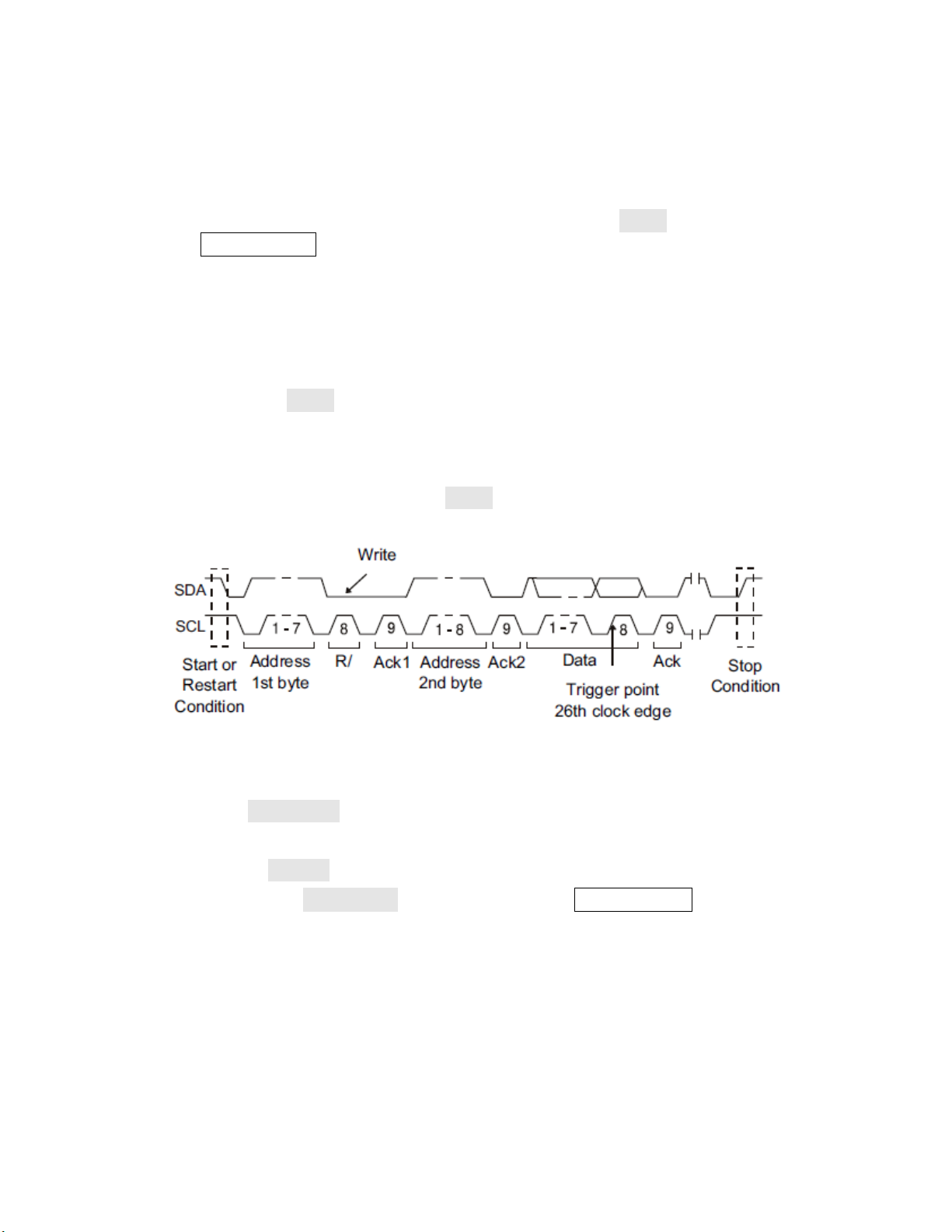
(hexadecimal). The oscilloscope will trigger after the start, address, read/write,
acknowledge, and data events occur.
c) If "don't care" (0xXX) is selected for data, the data will be ignored. The trigger will
always occur on the 17th clock for 7-bit addressing or 26th clock for 10-bit addressing.
If you have selected a three-byte trigger, press the Data2 softkey and turn the
Universal Knob to select the 8-bit data pattern on which to trigger.
10-bit Address & Data Condition - The oscilloscope triggers on a 10-bit write frame on
the 26th (or 34th) clock edge if all bits in the pattern match. The frame is in the format:
Frame (Start: Address byte 1: Write: Address byte 2: Ack: Data). The oscilloscope triggers
on a read or write frame in 10-bit addressing mode on the 26th clock edge if all bits in the
pattern match. Data2 shows 0xXX. For triggering purposes, a restart is treated as a start
condition.
Frame (Start: Address byte 1: Write: Address byte 2: Ack: Data: Ack: Data). The
oscilloscope triggers on a read or write frame in 7-bit addressing mode on the 34th clock
edge if all bits in the pattern match. Data2 is available. For triggering purposes, a restart
is treated as a start condition:
Figure 73 - 10-bit address & data condition
Data Length - The oscilloscope triggers when the SDA data length is equal to the value
set in the Byte Length softkey.
To set the oscilloscope to trigger on data length condition:
a) Press Address to set the SDA address length to 7-bit or 10-bit.
b) Press the Byte Length softkey and turn the Universal Knob to select the byte
length.
c) The range of the Byte Length is 1 to 12.
SPI Triggering
After the oscilloscope has been set up to capture SPI signals, you can trigger on a data pattern
that occurs at the start of a frame. The serial data string can be specified to be from 4 to 96 bits
long.
86
Page 88

1. Press the Setup button to enter the TRIGGER menu.
2. Press the Type softkey.
3. Turn the Universal Knob to select Serial.
4. Press the Protocol softkey to select SPI.
5. Press the Signal softkey to assign signals to the different channels and its respective
threshold.
6. Press the softkey and press the Trigger Setting softkey to enter the SPI TRIG SET menu.
Figure 74: SPI TRIG SET menu
7. Press the Trigger Type softkey to select the trigger condition.
MISO DATA (Master-In, Slave-Out) - for triggering on the MISO data signal.
MOSI DATA (Master-Out, Slave-In) - for triggering on the MOSI data signal.
8. Press the Data Length softkey.
9. Turn the Universal Knob to set the number of bits in the serial data string. The number of bits
in the string can be set from 4 bits to 96 bits. The data values for the serial string are displayed
in the MISO/ MOSI data string in the waveform area.
10. For each bit in the MISO/ MOSI data string:
a. Press the Bit Roll softkey. Turn the Universal Knob to select the bit location. As you rotate
the Universal knob, the bit is highlighted in the Data string shown in the waveform area.
b. Press the Bit Value softkey to set the bit selected in the Bit Roll softkey to 0 (low), 1 (high),
or X (don't care).
11. Pressing the All Same softkey will set all bits in the data string to 0 (low), 1 (high), or X (don't
care) at once.
12. Press the Next Page softkey to see the last menu item Bit Order.
13. Press the Bit Order softkey to set the bit order to LSB (least significant bit) first or MSB (most
significant bit) first. This will determine which bit will be used first when displaying data in the
serial decode waveform and in the Lister.
87
Page 89

Figure 75 - SPI trigger
UART Triggering
To trigger on a UART (Universal Asynchronous Receiver/Transmitter) signal, connect the
oscilloscope to the RX and TX lines and set up a trigger condition. RS232 (Recommended Standard
232) is one example of a UART protocol.
1. Press the Setup button to enter the TRIGGER menu.
2. Press the Type softkey.
3. Turn the Universal Knob to select Serial.
4. Press the Protocol softkey to select UART.
5. Press the Signal softkey to configure the channels to be either RX or TX and their voltage
threshold levels.
6. Press the key and press the Trigger Setting softkey to enter the UART TRIG SET menu.
Test Eq
uipment D
epot
- 8
517.8431 - 99 Washington Street Melrose, MA 02176
00.
TestEquipmentDepot.com
88
Page 90

Figure 76: UART TRIG SET menu
7. Press the Source Type softkey to select TX or RX.
8. Press the Condition softkey and set up the desired trigger condition:
Start - The oscilloscope triggers when a start bit occurs.
Stop - The oscilloscope triggers when a stop bit occurs on RX.
Data - The oscilloscope triggers on a data byte that you specify. For use when the device
under test data words are from 5 to 8 bits in length
a. Press the Compare Type softkey and choose an equality qualifier. You can choose
equal to, less than, or greater than a specific data value.
b. Use the Value softkey to choose the data value for your trigger comparison. This
works in conjunction with the Compare Type softkey. The range of the Value is 0x00
to 0xff.
Error - The oscilloscope triggers when a parity error.
Figure 77 - UART trigger
CAN Triggering
To set up the oscilloscope to capture a CAN signal:
89
Page 91

1. Press the Setup button to enter the TRIGGER menu.
2. Press the Type softkey.
3. Turn the Universal Knob to select Serial and press the Protocol softkey to select CAN.
4. Press the Signal softkey to configure the channels and assign to them the High or Low CAN
signal and to configure the SOURCE, which can be CAN_H, CAN_L, or CAN_H-CAN_L.
5. Press the Trigger Setting softkey to enter the CAN TRIG SET menu.
6. Press the Condition softkey and turn the Universal Knob to select the trigger condition:
Start - The oscilloscope triggers at the start of a frame.
Remote - The oscilloscope triggers on remote frames with the specified ID.
a. Press the ID Bits softkey to select the ID number 11 bits or 29 bits.
b. Press the Curr ID Byte softkey and turn the Universal Knob to select the byte to be set.
c. Press the ID softkey and turn the Universal Knob to set the ID.
ID - The oscilloscope will trigger on remote or data frames matching the specified ID.
a. Press the ID Bits softkey to select the ID number 11 bits or 29 bits.
b. Press the Curr ID Byte softkey and turn the Universal Knob to select the byte to be set.
c. Press the ID softkey and then turn the Universal Knob to set the ID
ID+DATA - The oscilloscope will trigger on data frames matching the specified ID and
data.
a. Press the ID Bits softkey to select the ID number 11 bits or 29 bits.
b. Press the Curr ID Byte softkey and turn the Universal Knob to select the byte to be set.
c. Press the ID softkey and then turn the Universal Knob to set the ID.
d. Press the Data softkey and then turn the Universal Knob to set the value of the first byte.
e. Press the Data softkey again to toggle between fields and then turn the Universal Knob
to set the value of the second byte.
Error -The oscilloscope will trigger when any form error or active error is encountered.
7. Press the Bus Configure softkey to enter the BUS CONFIG menu.
Press the Baud softkey and turn the Universal Knob to select the baud rate that matches
your CAN bus signal. The CAN baud rate can be set to predefined baud rates from 5 kb/s
up to 1 Mb/s or a custom baud rate from 1 b/s to 1 Mb/s. If the desired baud rate is not
listed, select Custom on the Baud softkey. Press the Custom softkey and turn the
Universal Knob to set the desired baud rate.
90
Page 92

Example
Figure 78 - CAN trigger
The picture below triggers on ID, the ID is 14b2d4ff, and the baud rate is 100 kb/s:
LIN Triggering
LIN triggering can trigger on the rising edge at the Sync Break exit of the LIN single-wire bus signal
(that marks the beginning of the message frame), the Frame ID, or the Frame ID and Data.
A LIN signal message frame is shown below:
1. Press Setup to enter the trigger menu.
2. Press the Type softkey.
3. Turn the Universal Knob to select Serial and press the Protocol softkey to select LIN.
4. Press the Signal softkey to select source channel for the LIN SIGNAL and its threshold level.
5. Press the Source softkey and select the channel for the LIN signal.
6. Press the Threshold softkey and turn the Universal Knob to select the LIN signal threshold
voltage level. The threshold voltage level is used in decoding and it will become the trigger
level when the trigger type is set to the selected serial decode slot.
7. Press the key to return to the TRIGGER menu.
8. Press the Trigger Setting softkey and turn the Universal Knob to select the trigger condition:
Break - The oscilloscope triggers when a start bit occurs.
ID (Frame ID) - The oscilloscope triggers when a frame with an ID equal to the selected
value is detected. Use the Universal Knob to select the value for the Frame ID.
ID + Data (Frame ID and Data) - The oscilloscope triggers when a frame with an ID and
data equal to the selected values is detected. Use the Universal Knob to select the value
for the ID, Data1 and Data2.
Data Error - The oscilloscope triggers when it detects data error.
91
Page 93
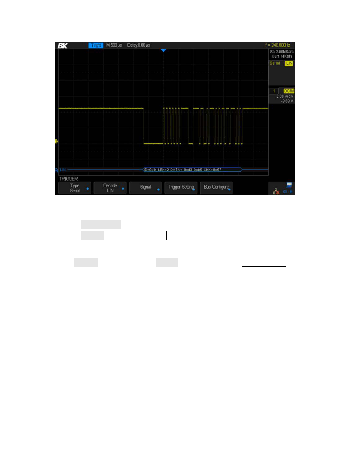
Figure 79 - LIN trigger
1. Press the Bus Configure softkey to enter the BUS CONFIG menu.
2. Press the Bit Rate softkey and turn the Universal Knob to select the baud rate that matches
your LIN bus signal. The LIN baud rate can be set to predefined baud rates from 600 to 19200
or a custom baud rate from 300 to 20000. If the desired baud rate is not listed, select Custom
on the Bit Rate softkey. Press the Custom softkey and turn the Universal Knob to set the
desired baud rate.
Test Equipment Depot - 800.
517.8431 - 99 Washington Street Melrose, MA 02176
TestEquipmentDepot.com
92
Page 94

6 Math Functions
Math Operation
Symbol
Unit
Addition or subtraction
+ or -
V, A
Multiplication
*
V∧2, A∧2 or W (Volt-Amp)
Division
/
Ω, S, or None
FFT
FFT
dBVrms, Vrms, dBArms, Arms
Differentiation
d/dt
V/s or A/s
Integration
∫dt
Vs or As
Square root
√
sqr(V) or sqr(A)
Note: If the analog channels used with the math function are truncated (waveforms do not display
on the screen completely), the resulting math waveform will also be truncated.
The 2560 Series oscilloscopes support math operations between the analog channels and
reference waveforms, including addition ( + ), subtraction ( - ), multiplication ( * ), division ( / ),
FFT, differentiation ( d/dt ), integration (∫dt), and taking the square root (√). The resulting math
waveform is displayed in white and labeled with the letter M at the left of the screen.
6.1 Math Operations and Their Units
Use the channel function menu (page 2) to set the unit of each channel to V or A. The
oscilloscope’s math operations are:
Addition, subtraction, multiplication, and division require two waveforms. FFT, differentiation,
integration, and taking the square root operate on a single waveform.
6.2 Addition and Subtraction
When you select addition or subtraction, The Source A and Source B values are added or
subtracted point-by-point and the result is displayed.
1. Press the Math button to enter the MATH menu.
2. Press the Operation softkey and turn the Universal Knob to select + or -.
3. Press the Source A and Source B softkeys and use the Universal Knob to select the two
sources to add or subtract. The analog channels and the reference waveforms (REF) can be
used as sources.
4. Press the Invert softkey to invert the result.
5. Press the Scale softkey and turn the Universal Knob to scale the V/div.
6. Press the Position softkey and turn the Universal Knob to move the result’s vertical
position.
93
Page 95

6.3 Multiplication and Division
Note: Spectral leakage can be decreased when the proper window function is used. The
oscilloscope provides four kinds of FFT window functions which have different characteristics and
are applicable to different waveforms. Please read the table below to make an appropriate
window choice.
When you select multiplication or division, the Source A and Source B values are multiplied or
divided point-by-point and the result is displayed. Division by a waveform that passes through
zero can result in positive or negative spikes in the graph.
1. Press the Math button to enter the MATH menu.
2. Press the Operation softkey and turn the Universal Knob to select * or / to multiply or divide.
3. Press the Source A and Source B softkeys and turn the Universal Knob to select the two
sources for the math operation. The analog channels and reference waveforms can be used
as sources.
4. The Invert softkey is available to invert the result.
5. Press the Scale softkey and turn the Universal Knob to scale the V/div.
6. Press the Position softkey and turn the Universal Knob to move the result’s vertical position.
6.4 FFT (Fast Fourier Transform)
The FFT operation is used to compute the fast Fourier transform of the analog input channels or
the reference waveforms. The FFT takes the digitized time record of the waveform and
transforms it to the frequency domain. When the FFT function is selected, the FFT spectrum is
plotted on the oscilloscope display as magnitude in dBVrms or Vrms (or corresponding current
units) versus frequency. The readout for the horizontal axis changes from time to frequency
(Hertz).
Some uses of the FFT operation are:
Measure harmonic components and distortion in a system.
Measure the noise characteristics of DC power.
Analyze vibration.
Evaluate the effectiveness of a filter.
To display a FFT waveform
1. Press the Math button to open the MATH menu.
2. Press the Operation softkey and turn the Universal Knob to select FFT. The resulting FFT
waveform is displayed in white.
3. Press the Source softkey and turn the Universal Knob to select the source for the FFT
operation. The analog channels can be used as the source.
4. Press the Window softkey and turn the Universal Knob to select an appropriate window.
94
Page 96

Window
Characteristics
Applications
Rectangle
The best frequency
resolution, but the poorest
amplitude resolution. Similar
to when no window is
applied.
Transient or short pulses. Sine
waveform with the same amplitude
and rather similar frequencies. Wide
band random noise with relatively
slowly changing waveform spectrum.
Hanning
Better frequency resolution;
poorer amplitude resolution.
Sine, periodic and narrow band
random noise.
Hamming
Somewhat better frequency
resolution than Hanning.
Transient or short pulse, the signal
levels before and after the
multiplication are rather different.
Blackman
The best amplitude
resolution; the poorest
frequency resolution.
Single frequency signal, search for
higher order harmonics.
Table 7 - FFT window instructions
5. Press the Center softkey and turn the Universal Knob to set the frequency of the center
vertical line.
6. Press the Hz/div softkey and turn the Universal Knob to set the vertical range of the display.
7. Press the FFT Zoom softkey and turn the Universal Knob or turn the horizontal scale knob to
select the desired magnification (1X, 2X, 5X, 10X). Set the FFT Zoom to a higher magnification
to see more details of the FFT waveform.
8. Press the Scale softkey to select the units per division for the vertical axis. The units of the
vertical axis can be dBVrms (logarithmic) or Vrms (linear). If you need to display the FFT
frequency spectrum with a large dynamic range, dBVrms is recommended.
9. Press the Reference Level softkey and turn the Universal Knob to adjust the position of the
FFT's vertical position.
10. Press the Unit softkey and turn the Universal Knob to display with a Vrms (linear) or dBVrms
(logarithmic) vertical scale.
11. Press the Display softkey to select Split, Full Screen, and Exclusive display mode.
Split: the source channel and the FFT operation results are displayed separately. The time
domain and frequency domain signals are displayed on separate portions of the screen.
Full Screen: the source channel and the FFT operation results are displayed in the same
window to view the frequency spectrum more clearly and to perform more precise
measurements.
Exclusive: only the FFT operation results are displayed in full screen.
95
Page 97

Table 8 - FFT waveform in split mode
6.5 Differentiation
The differentiation operation (d/dt) calculates the discrete time derivative of the source
waveform:
di = approximation to the derivative at the i
y = data point from the source channel
i = data point index
Δt = point-to-point time difference
th
point
The dx softkey under d/dt math function operation menu shows the point-to-point time
difference, and it is adjustable from 0.02 divisions to 0.40 divisions. Since the oscilloscope has 50
pixels per division, the number of samples in Δt is 50*dx. Higher values of dx reduce the noise
that is an artifact of numerical differentiation but will reduce the calculated slope at
discontinuities. Conversely, lower values of dx increase the noise but represent slopes at
discontinuities better. If the signal is periodic, averaging the waveform may help reduce noise.
96
Page 98

Figure 80 - Differentiation function
n
0i
i0n
ytcI
You can use the differentiation function to measure the instantaneous slope of a waveform. For
example, the slew rate of an operational amplifier may be measured using the differentiation
function. Note your measured values will depend on your choice of dx.
6.6 Integration
The MATH operation ∫dt (integration) calculates the numerical integral of the selected source.
∫dt calculates the integral of the waveform's data using the trapezoidal rule. The equation is:
I
= approximate numerical integral of waveform with respect to time
n
c
= arbitrary constant
o
Δt = point-to-point time difference
y
= sampled data point of selected analog channel or reference waveform
i
i = data point index
The integration menu provides an Offset softkey that lets you set a DC offset correction for the
input signal. Small DC offsets in the integration function input (or even small oscilloscope
calibration errors) can cause the displayed integrated waveform output to ramp up or down. This
offset correction helps you level the integrated waveform.
Test Equipment Depot - 800.
517.8431 - 99 Washington Street Melrose, MA 02176
TestEquipmentDepot.com
97
Page 99

Figure 81 - Integral without offset
Figure 82 - Integral with offset
Like the other math functions, the Scale and Position softkeys are supplied to enlarge or reduce
the displayed waveform's amplitude and position it vertically on the screen.
Press the Gate softkey to open the Gate menu. Use the cursors to limit or gate which section of
the waveform gets integrated.
98
Page 100
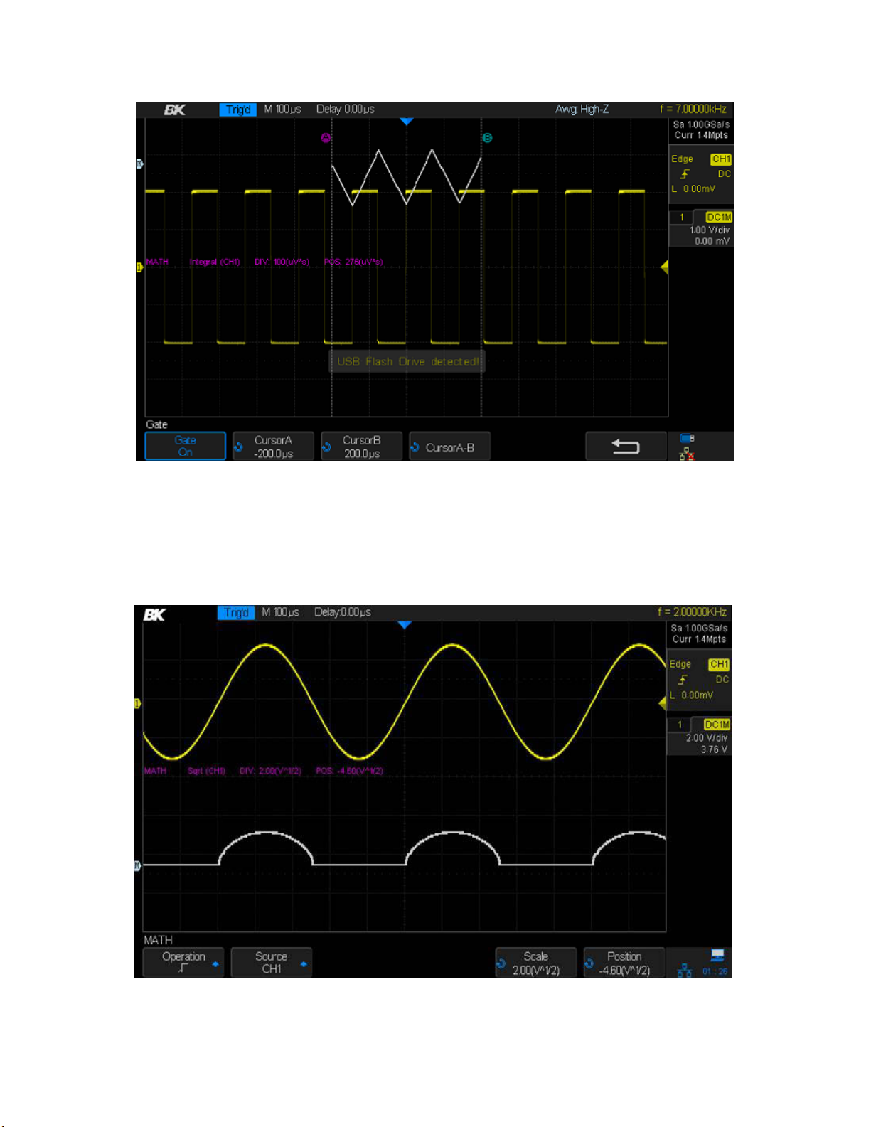
Figure 83 - Integrate gate function
6.7 Square Root
This function calculates the square root of the selected source. Points where the waveform's data
are negative are set to zero.
Figure 84 - Square root
99
 Loading...