

Page 1
F
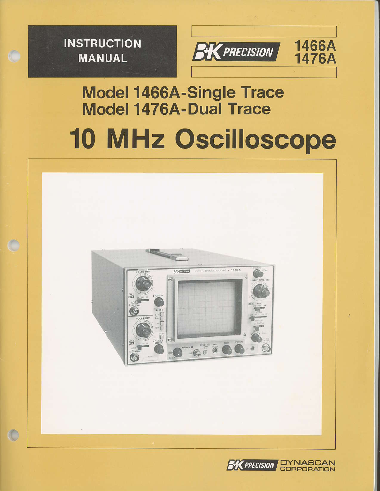
1466A
1476A
Model 1466A-Single
Model
10
MHz
1476A-Dual
Oscilloscope
'4t"r-
Trace
Trace
&
--F
g
"L
@-,a,
&:
*.-
b
(,J
-'-.''l''."-a.]&:|
ffi@@tg#"le,aN
Page 2

TEST INSTRUMENT
WARNINC
SAFETY
Normcl use of lest equipment exposes
shock becouse tesling musl oflen be
electricol shock cousing l0milliomps
humon heorlbeots.
hozordorrs
on even
normol work hobits
exposed high voltoge, ond tho+ will
conloci wilh o high voltoge.
observe the
2.
3.
4.
q
since it con
greoter
following sofety
Don'l expose high volloge needlessly in the equipment under test. Remove houslngs ond
covers
voltoge circui+s.
lf
high
points
Use on insuloted floor moieriol or q lorge, insuloted floor mot to slond on, ond on
insulqled work surfoce on which 1o
oomp
Use the time-proven
probe,
provide o good ground
When
porlaon.
When
some
time the equipmenf is connected lo on oc ouilef, even if the equipment is turned off.
only when
possible,
voltoge
in defective equipmeni.
ol weT.
using o
iesfing
power
Voltoge
threot becouse such volloge con more eosily
should include oll occepted
fomiliorize
poinls.
porticulorly
Be
probe,
oc
inpuf circuits such os the on-off switch, fuses,
os low os 35 volts dc or oc rms should be considered dongerous ond
produce
necessory.
Dischorge
powered
o lelhol current under certoin condiiions. Higher voltoge
s+eer
will
You
precoulions:
Turn off
high-voltoge
yourself
However, remember thot high voltoge moy oppeor ol unexpecled
"one
hond
coreful
return
+ouch only the
pqth,
equipmenf, remember fhot
you
to o cerloin omounf of donger from elecfricol
performed
of
current to
currenl owoy
significontly reduce the
wiih ihe equipmeni being tested ond the locolion of its
ploce
in ihe
ovoid
io
where exposed high
poss
through the heorf will
produce
proctices
equipment while
copocifors
eqrJipmeni; moke cerioin such surfoces
pockef"
confocting o neorby metol object thot could
insuloted
lechnique
por+ion.
ihoi will
your
from
moking
ofter removing
while hondling on inslrument
Never louch the exposed iip
oc
line
voltoge
a lelhol current, Your
prevent
heorf in cose of occidentol
risk
foctor if
lest
connections
power.
voltoge
power
is
tronsformer, efc. ony
present.
is
contoct with
you
usuolly
An
s+op most
poses
know
presenl
ond
in high-
cre nof
on
7.
Some equipmenl wilh o lwo-wire oc
plugs,
equipmenl. A
When ihe
touched.
instrumenfs or the equipmenf under iest moy result from
mosf iesi inslrumenls
ments in
oc ouile+ ond
Tronsformer, or
To be on the sofe side, treqf oll fwo-wire oc
you
8. Never work olone.
CPR
is the
ore sure it hos on isololed chossis or on eorth
(cordio-pulmonory
"hot
chossisrriype. This includes
ploslic
cobinet
Not only does ihis
iihot
chossisr equipmenl, olwoys conneci dn isololion lronsformer
lhe eouiDment under fest. TheB&K-PrecisionModel TR-l!0 lsolotion
Model 1653
or wooden cqbinef insuloles the chossis lo
is removed for servicing, o serious shock
present
(including
or
1655 AC Power Supply
Someone
resuscitoiion)
should be neorby to render oid if necessory. Troining in
power
this oscilloscope) lo o
first
cord, including some with
most
o dongerous shock hozord,
powered
oid is highly recommendeo,
polorize{ power
recenl felevision receivers
prolecl
lhot
eqr.ripment
ground
hozord
connecling
chossisr!. To moke mecsure-
is suifoble
chossis.
exisfs if the chossis
but domoge fo
lhe
for mos+
"hot
qs
qnd
oudio
the customer.
is
tesi
ground
between
opplicotions,
chossisr'unless
leod
of
the
Page 3
lnstruction
Manual
for
Model 1466A-Single
Model
10
ThiE sylnbol oD oscilloscope
Il1anual fo! furthe!
syEbol
inforEatiod
appears ir the Danual
1476A-Dual Trace
MHz
given.
is
OscilloscoPe
meaas
precautionaty
ntefet
iofolbation".
\there the corre8ponding
Trace
to iD8truction
This
DYNASCAN
COF|PORATION
West Cortland Street
6460
Chicago,
Illinois 60635
Page 4
TAsLE
OF CONTENTS
page
TEST INSTRUMENT SAFETY
FEATURES
bPrru.Lt luA ltuN b .
CoNTROLS AND INDICATORS.
OPERATING INSTRUCTIONS .
Safety Precautions
EquiphentPlotectionPrecautions.,,......,13
Opelating Tips
Initial
Single
Dual Trace Display,
Tliggeling
Magnified Sweep Operation,
X-Y OpelatioD
Video Sigrral Obselvation.,,.
APPLICATTONS
SINGLE-TRACE APPLICATIONS..
DUAL-TRACE
x-Y MODE APPLTCATIONS
Statting Procedure . . .
Tlace Display,.
DC Voltage
Peak-to-PeakVoltageMeasureErents
TitDe MeasureDents
Flequency MeasuteEents
Pulse Width MeasureDents
Relative
Tirle Diffelence
Elimination
Phase Difference
Phase Measurements..
Flequency
MeasulerDents ...
MeasuleEerts.
APPLICATIONS.
Meaaurements.
of an
Undesiled Signal CoEponent
MeasulemeBts
Response Measrferients
. . . . inside front
.............1
. . .. ...,......2
.... ..........5
...... 13
........,,,..13
..,.,...14
........,,,,.15
,.......,.15
........,...15
,,,,.......16
......18
....... . 19
,,,,.........19
,,....... 20
......... 20
.......... Z0
......21
. ......... 21
....
. ,
. , . . .
., .......,,,
. .,..
, .........22
,.,.,......23
.. , ....... 24
....,......27
.,,..,...27
.,,,,,,21
.,,. .. . ,. 28
...........
....... 31
cove!
o
,, 30
30
OPTIONAL ACCESSORIES
MAINTENANCE
Fuse ReplaceEent
Case Ren:oval
Pedodic
Calibration
InstruEent
Additional Servichg
WARRANTY
LIMITED
ONE-YEAR \IIARRANTY
.
Adjustmeats ......
Cbeck ..,
Repair Selvice. .
SERVICE
,. ,
Informatio
INSTRUCTIONS
...... 32
33
33
34
.
34
34
.,,,,, . . . . . . .
inside
inside back
back cover
cover
Page 5
FEATURES
c
FEATURES
AND DUAI-TRACE MODELS
CRT FEATURES
Rectangula!
mete! viewing alea. High blighttess, Z kV
accelelation voltage. Internal 8 x 10 divi-
glaticule
sion
Trace lotation electrically adjustable flol!
panel.
front
10
MHz BANDWIDTH/3s ns RISE
Conselvatieely rated
to 10 MHz. Tliggeling beyond 10 MHz.
HIGH SENSITIVTIY
width. Selectable I ov/die sensitivity to
7 MHz, Pellrlits the low capacitance,
iEpedance 10:1
all DeasuleDents, thus assuring minimuD
ci!cuit
CALIBRATED
Acculate tiroe
on 19
0.5
fo!
Sweep
b!ated !anges.
X1O
AUows closel examination of waveforms,
increases baximurr sweep rate to
loading.
caliblated ranges from 0.5 s/div to
tb/div,
viewing wavefolms from dc
SWEEP MAGNII"ICATION
plovides
ti[|e fully adjustable between cali-
OF SINGLE-TRACE
CRT with large 8
elihinates
-3
dB
probe
TlME MEASUREMENTS
(pe!iod)
to be used fo! neally
measuleroents
evely sweep rate needed
x 10
pa-lallax
TIME
bandwidth is dc
to
10
50
centi-
euor.
high
(j3%)
M}Iz.
ns/div.
1TRSATILE TRIGGERING
Selectable INTernaI, LINE
ExTernal tliggelirg. Fully variable trigger
LE\EL control.
VIDEO SYNC
Selectable FRAME o! LINE tliggering for
observing composite video wavefolms.
X-Y OPERATION
Extelnal trigge! input
trace Inodel)
(X-axis)
(charnel
vertical deflection
Z
AXIS INPUT
Intensity modulation capability. Tlace
blightens with
patible.
BUILT-IN PROBE ADJUST SQUARE
A 0,5 V
pelrDits probe
DUAL TRACE
Two identical veltical
rnit sihultaneous viewing of two waveforms. Alternate or
at all
deflectior while the vertical input
ADDITIONAL FEATURES
sweep rates,
can be applied as holizontal
1on dual-tlace
(Y-axis).
positive
p-p,
1 kHz
compersation ailjustment.
DUAL.TRACE
square wave
chop sweep selectable
(50/60
(channel
sigrali TTL com-
MODEL
input cha]nlels
2
model)
OF
on
plovides
WAVE
generator
Hz),
dual-
or
pe!-
CALIBRATED VOLTAGE MEASUREMENTS
Acculate voltage measueDents
12 calibrated langes Irot! 1 rnv/div to 5 V/
div. Vertical
calibrated
AUTO SWEEP
Selectable AUTO sweep
witlout tligger input, automatically
to tliggered sweep operation when adequate
trigger is applied.
gain
!anges.
fully adjustable betpeen
plovides
{J370)
sweep
levetts
otr
SUM
AND DIFFERENCE CAPABILITY
Permits algebraic addition
chanDel 1 alld channel 2 waveforms, dis-
played
ential voltage and distoltion measurements.
EXPANDED
Selectable CH 1. CH Z. or V. MODE
Ir V. MODE, each wavefolm displayed
becomes its
ing
as
a single trace. Useful fo! diffeF
INTERNAL TRIGGERING
own trigger
in ALT dual-sweep mode).
or subtraction of
(alteltrate
triggeF
source.
Page 6
PECIFICAIIONS
)
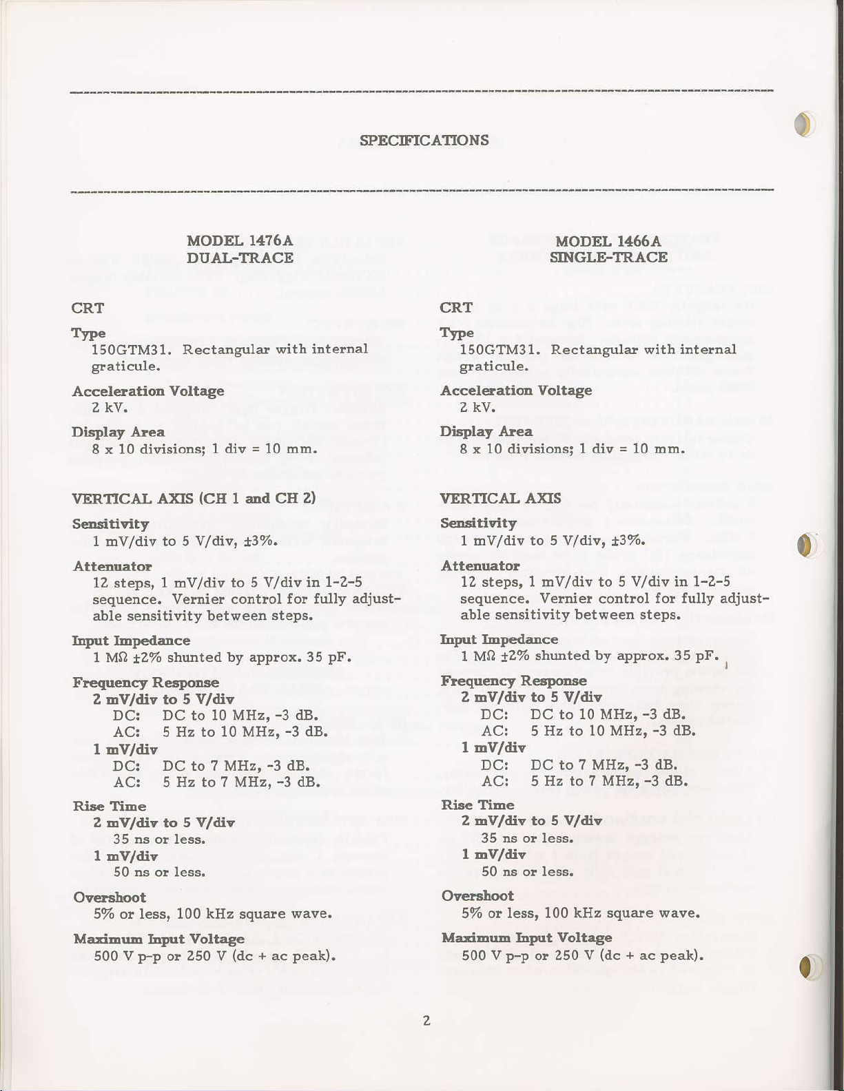
MODEL 14?6A
DUAI-TRACE
CRT
Type
150GTM31.
graticule, graticule.
Accel€ratioa Voltage
Rectan8ular
with internal
2 kv.
Dtsplay Area
8 x 10 divisions;
i2%
AXIS
shunted
VERTICAL
Sensitivity
1 rDv/div to 5
Attesuato!
12 steps, 1 mv/div
sequence.
able sensitivity between steps,
Lnput Ibp€dance
1
Mn
Frequency Re6porBe
2 Dvlti? to 5
Dc: DC to 10
AC: 5 Hz to 10 MHz,
I
mV/div
DC: DC to ? MHz,
AC! 5 Hz to 7
Rise fiEe
2 bV/diy to 5 V/div
35 ns or less.
I DV/diY
50 rs o! less.
I div = 10 mm.
(CII
I and CI{ 2} VERTICAL AXIS
!/?\a,
Vemier contlol fo!
v/dtv
t3%.
to 5 V/div in
by applox, 35
MI{z,
-3
-3
-3
dB.
-3
dB.
dB.
Mltz,
1-z-5 12 steps, I mv/div to 5
fully adjust- sequence. verIrier control fo! fully adjust_
pF.
dB. AC: 5
CRT
TYpe
150GTM31, Rectangular with irrternal
Acceletation Voltage
2 kv.
Display Atea
8!
SeDsitivity
t hv/div to 5 V/dia'
Atteluatoa
able sensitivity
Lq'lrt ImPedance
1 MO
Ftequency
z hv/div to 5 v/diY
l mv/div
Rise TiEe
2 EV/div to 5 V/diY
l mv/div
MODEL 14664
SINGLE-TRACE
10 divisionsi l div= l0 ncm.
t3%.
V/div
between stePs.
shunted
Jz%
Re4onse
DCr DC
Hz to 10 MHz'
DC: DC to ? MHz'
AC: 5 Hz to ? MHz,
ns or less.
35
50 ns or less.
by aPprox.
10 MHz'
to
-3
-3
-3
dB.
-3
dB.
dB.
in
35
dB.
1-2-5
PF.
0
,
OyetBhoot
57o or less, 100 kH? squale
MariErb
500 V
Lqrut
p-p
Voltage
or 250
v
(dc
Ovelshoot
wave. 57o ot less, 100 kHz
Mati|bub IrFrt Voltage
+
peak).
ac
500 V
Fp
or 250
square wave.
{dc
+
ac
V
peak).
fr
Page 7
SPECIFICATIONS
MODEL 1,{?6A
DUAI.-TRACE
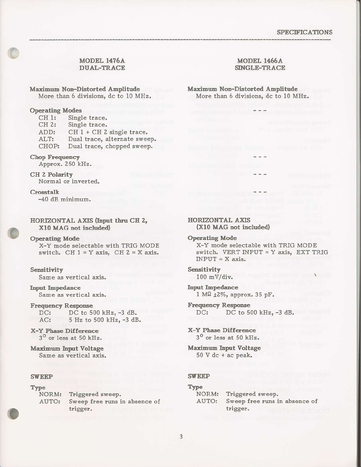
MariDuD Nc-Distolted AElrfitude
Mole tha! 6 divisions, dc to 10 MHz.
OpeatiDg Modes
CH 1:
CH 2r Single tlace.
ADDI CH
ALT: Dual tlace, alternate
CHOPI
Chop Frcquercy
Applox. 250 kllz.
CIl 2
Potaity
Nolrnal o! invelted.
Crosstall
-40
HORZONTAL AXIS
xlo
Op€latirg
X-Y
switch, CH
Single trace.
+
1
Dual tracel choppeil sweep.
dB
minif|um.
MAG Dot includeo
Mode
mode selectable
1=Y axiE, CH2
2 single trace.
CH
(IDput
with TRIG MODE
thu
sweep.
cE z'
=X
axis.
MODEL 1466A
SIIIGLE-TRACE
Majrimurn Nd-Dbtolted ADplitude
Mole than 6 divisions. dc to l0 MHz.
EOR.ZONTAI AXIS
(Xlo
MAG Dot iaduited)
Op€tr.ting Mode
switch. VERT INPUT = Y axis,
INPUT = X
axis.
MODE
EXT TRIG
SeDsitivity
Sa!!e as vertical axis.
InFrt IEIr€daDce
Same as veltical
Frequelcy R€slroDse
X-Y
DC:
AC:
Phaae
DC to 500
5 Hz
Differ€dce
axis.
500 kHz,
to
30 o! less at 50 kHz.
Mariorrln
l4rtt
Voltege
Same as vertical a:is,
SWEEP
Tt?e
NORM: Triggeled sweep.
AUTO: Sweep
free runs
trigge!.
kgz,
-3
dB.
-3
dB.
absence
in
ot
ScDsitivity
100
Dv/div.
hput
IDpeilarcc
1 MA
,ZVo,
applox. 35
pF.
Freq|rescy R€6Pdse
DCI DC to 500 kHz,
-3
dB.
X-Y Phare Differeoce
30 o! less at 50 kHz.
Maxirrnb
50 V dc + ac
l4nrt
Voltege
peak.
SYEEP
TyPe
NORM: Tliggeled sweep,
AUTO: Sweep free lrlns in absence
tligge!.
of
Page 8
SPECIFICATIONS
MODEL
DUA-L-TRACE
1476A
0
MODEL 1466A
SINGLE-'TRACE
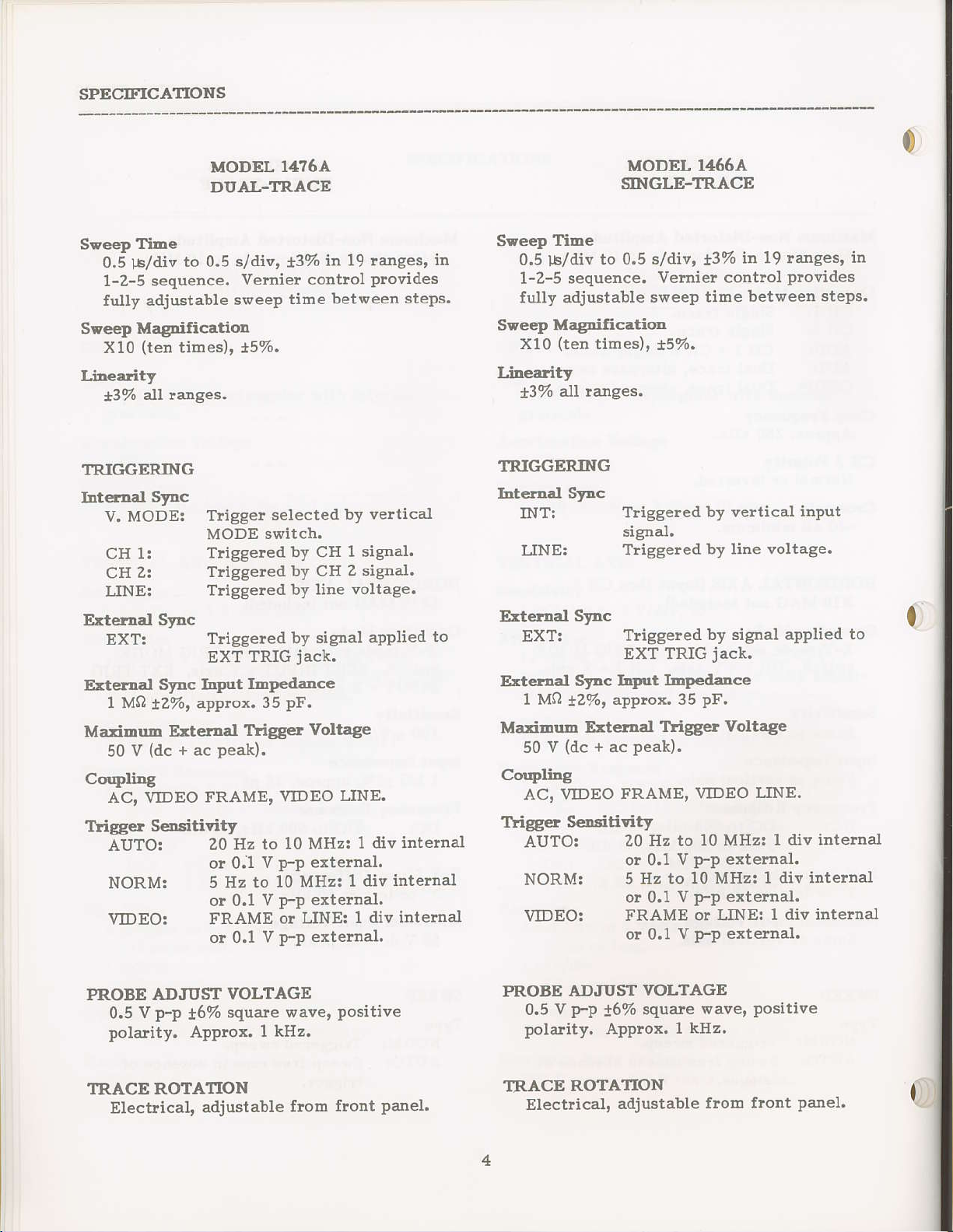
Sveep
SPeep MagnificatioE
Linearity
TRIGGERING
htefltal
ExteEnel
E:terdal
Ma:iDnb
Coupling
Ttigget
TiEe
0.5
lb/div
1-2-5
fully adjustable
X10
f3%
V. MODE:
CH 1l
cH
LINE:
ExT:
1 MQ
v
50
AC, VIDEO FRAME,
AUTO!
to 0.5 s/div,
sequence.
(ten
tihes)' *5%.
all rances.
SFc
z:
SFc
SFc lq'|tt
approx.
tzvo,
E:ternal
(dc
+
ac
Seltsitivity
Tligger
MODE switch.
Tliggeled
Triggered
Triggered
Triggered
EXT
peak).
20 Hz
o! 0.1
NORM: 5 Hz
o! 0,1
VIDEO:
FRAME ot LINE:
or 0.1 V
13%
Vemie!
s\oeeP
time
selecteil
TRIG
IEPedance
pF.
35
1ligger
VIDEO
to 10 MHz:
V
P-P
to 10
V
P-P
p-p
in 19 ranges'
control
between steps.
by Yeltical
by CH
by CH
by line
by signal
jack.
1 signal.
Z signal.
voltage.
Voltage
LINE,
1 div
extelnal.
MHz: 1 div
external.
1 div
extetnal.
plovides
aPPlied
internal
internal
intemal
to
in
Sideep
Seeelr
Lin€aiity
TRIGGERING
htetlal SFc
Eternal
TiEe
0.5
l-b/div
1-2-5 sequence.
Jully
Xl0
t3%
INT:
LINE:
to 0.5 s/div,
adjustable swee? time
Magdfication
(ten
times),
all langes.
Tliggered by veltical
signal.
Triggered
SFc
EXT!
Triggeled
EXT
Erteraal SFc hlirt
1 Mn
Maxinu.E
50 v
(dc
!2%,
E
+
(tetnal
approx. 35
ac
coqrliDg
AC, \,TDEO
FRAME,
Ttigg€t SeDsitivity
AUTO:
Z0 Hz to
o! 0,1
NORM:
5 Hz to
or 0.1
VIDEO!
FRAME
or 0.1
t3va
vernie! contlol
15%.
by
by signal aPPlied
TRIG
jack.
lDpedance
pF.
TrigS€t Voltage
peak).
VIDEO LINE.
10 MHz: 1 div
p-p
v
10 MHz: 1 div
p-p
v
or LINE: I div
p-p
V
19 langes, in
in
plotides
bet\aeen stePs.
input
voltage.
line
external.
internal
et ternal.
extetnal.
to
internal
intemal
J6%
VOLTAGE
square
PROBE ADJI'ST
p?
v
0.5
polality. Applox.
TRACE ROTATION
Electrical,
adjustable
wave,
I kHz.
frorn front
Positive
Panel
PROBE
0.5
polarity.
TRACE
Electlical,
ADJUST
p-p
v
!6%
Approx.
ROTATION
VOLTAGE
squate
1 kHz.
adjustable
\taver
positive
froDl flont
panel.
Page 9
SPECIFICATIONS
c
MODEL 14?6A
DUAI-TRACE
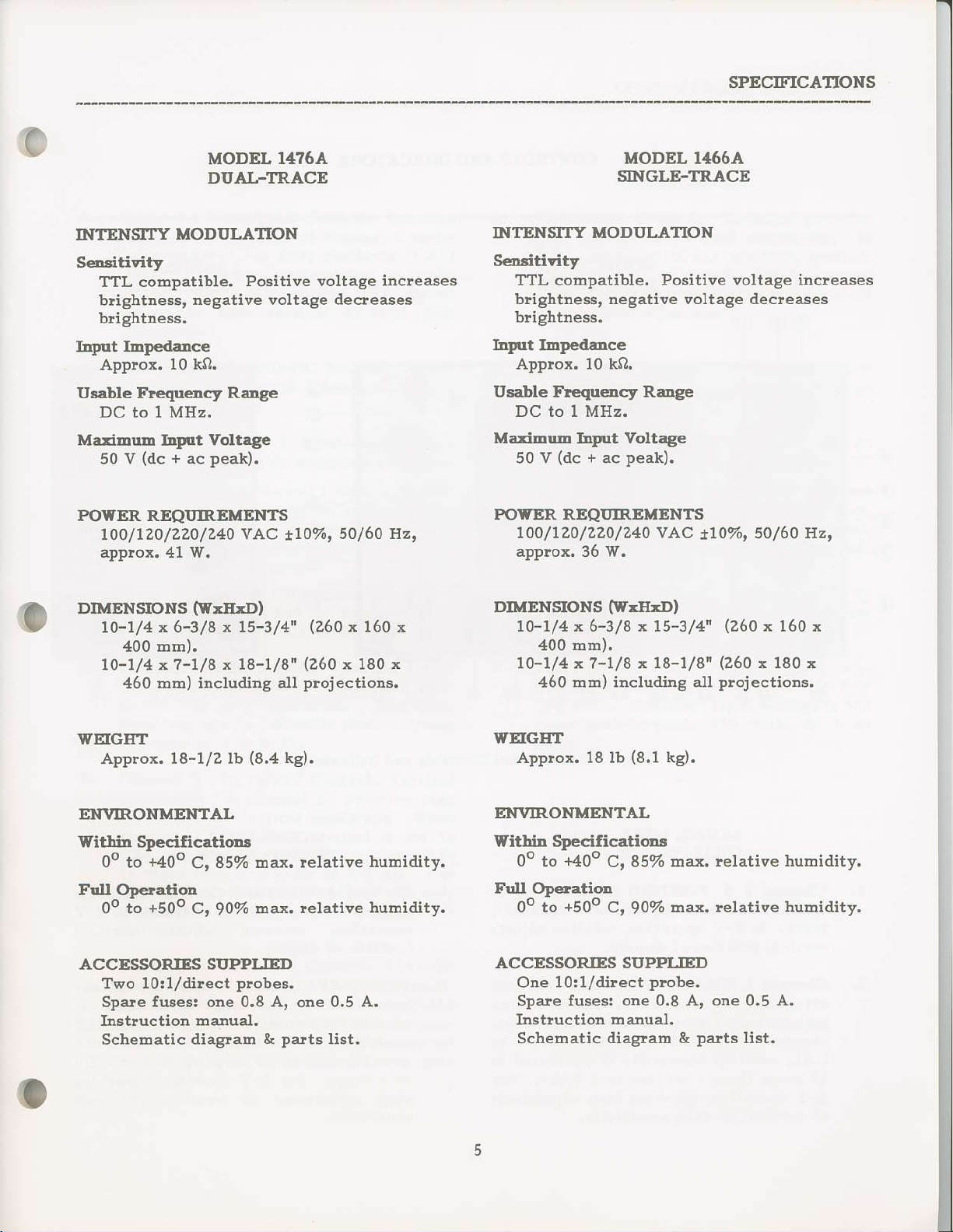
INTENSIIY
SeDsitivity
TTL compatible.
brightness,
blightness.
IrFt
IEp€dance
Approx.
Usable FlequeDcy
DC to 1MHz.
MaritDuo lq'lt
50 V
POWER REQI]IREMENTS
MODUI.ATION
Positive voltage
n€gative voltage decleases
10 kO. Applox. 10 kQ.
RaDge
Voltage
(dc
+
peak).
ac
1oo/1Zo/ZZ0/240 v AC
applox. 41 w.
tro%,
INTENSITY MODULATION
S€lritivity
incleases TTL comPatible.
brightness, negative voltage decreases
brightness.
lrFrt ImPedance
Usable Frequency Range
DC to lMHz.
Marimuh lrFtt Voltage
V
50
POWER REQI'IREMENTS
50/60 llz,
100/720/220/240 VAC
apprcx.36 w.
(dc
UODEL 1466A
SINGLE.TRACE
Positive voltage increases
peak).
+ ac
!10%'
50/60 Hz'
DTENSIoNS
(wJIxD)
10-1/4 x 6-3/8 x 15-3/4"
4oo mm).
10-1/477-1/8x 18-1/8"
460 mlr|) including all
WEIGFT
Approx. 18-1/2 lb
(8.4
ENVIRONMENTA'-
Within SpecilicatioD.s
to
+40o
85% Elax. lelative
C,
0o
Full ODetatioa
oo io
+5Oo
C,90%
max. relative bumidity.
ACCBSSORIES SUPPIJED
Two lo:1/direct
Spare fusesi one 0.8
plobes.
A,
Instruction roanual.
ScheEatic diag?am
&
(260
(260
x 180
projections.
kg).
0.5 A.
one
parts
list.
x 160 x
x
huhidity.
DIMENSIoNS
10-1/4 x 6-3/8 x 15-314"
(wrl{tD)
(260
4oo mm).
10-1/4
z?'7/8
460 mm) including all
r 18-1/8'(260 x 180 x
plojections.
WEIGET
(8,1
Applox. 18 lb
kg).
EIOVIRONMENTAL
Yithin Specilicationa
++oo
O" to
C, 85%
max. relativ€ humidity.
Fnll OpetatioD
+5Oo
Oo to
c, 9O7o hax. lelative huEidity.
ACCESSORIES SUPPLIED
One
lo:1/direct
probe.
spare fuses: one 0.8 Ar one 0.5 A.
Instruction
Schematic diaS"arD &
flanual.
patts
x 160 x
lisi.
Page 10
COIITROLS AND INDICATORS
MODEL 1,176A'
DUAL-TRACE
MODEL I,166A
SINGLE-TRACE
Fip. 1. Front Panel
MODEL
DUAI-TRACE
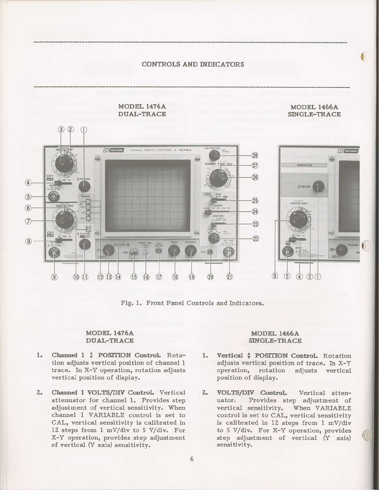
Charrel 1 i POSIIION C@trol. Rota-
adjusts vertical
tion
tiace. IJI X-Y operation, lotation adjusts
veltical
Chalrel l.LTS/DMcrDttoL Vertical
attenuator Io!
adjustEent
chajlnel MRIABLE
CAL,
12 steps tfolt| 1 nv/div to 5 V/div, For
X-Y operation,
of
vertical
position
of veltical sensitivity, Igle,l
vertical
(Y
14?6A
position
of display.
channel 1. Plovides step
sensitivity is calibrated in
provides
axis) sensitivity,
of clannel 1
cortrol is set to
step adjustoent
Contlols
l.
and
Iirdicators.
MODEL li166A
SINGLE-TRACE
V€ctical
adjusts vertical
operation, lotation
position
VOLTS/DW C.dbol.
uator. Ploviiles
vertical sensitivity.
contlol is set to CAL,
is calibrated in 12
to 5 V/div.
step adjustoert of vertical
sensitivity.
POSIrION
i
position
of display.
step adjustbent of
steps from 1 rhv/div
t-or X-Y operation,
Coltrot- RotatioD
of tface. In X-Y
adj$ts
Veltical atten-
V/hen VARIABLE
vertical sensitivity
ve.tical
plovides
(Y
axis)
Page 11
CONTROLS AND INDICATORS
(
MODEL 1,176A
DUAL-TRACE
MODEL 1466A
SINGLE-TRACE
3.
CharDel
plovides
cal sensitivity. In fuUy clockwise
position,
brated. For X-Y operation, this contlol
selves as fine vertical
adjustment.
Charre! 1 AC-GNIFDC S*itcbposition
AC;
I.RIABLE
fine control of chadrel 1velti-
vertical attenuator is cali-
leve! s\ditch selects channel
Channel 1 input capacitively
C@t
oL Rotation
{Y
coupledi dc component blocked.
GND:
Opens
glounds
lifie!. This
signal, zero-volt dc base line
for refelence.
channel 1 signal
input to vertical
provides
DC: Channel 1 input ditect coupled;
both ac arld dc component of
waveform displayed.
ChaDDel I INPUT Jach- Channel 1 ve!-
tical input conn€ctol; Y axis input
nector for X-Y
input voltage is 500 volts
250 volts dc + ac
opelation. Maximum
peak-to-peak;
peak.
axis)
path
a zero-
(CAL)
gain
Three
and
amp-
con-
3.
VARIABI.E
fine
contlol of vertica-l sensitivity. In
fully
attenuato!
ation, this control serves as fine veltical
(Y
4.4.
AC-GND-DC Svitcb- Tbree-position
1
Ieve!
Iing:
AC: Input
GND: Opens signal
clockwise
axis)
switch selects veltical input coup-
Control. Rotation
(CAL)
is calibrated. For X-Y opeF
gain
adjustment.
capacitively coupled! dc
component blocked.
input to vertica.I amFlifie!.
This
zelo-volt dc base line for ref-
plovides
position,
path
a zero-sigtral,
and
provides
veltical
grounds
DC: Iflput direct coupled; both ac
and dc component oI wavefou
displayed.
VERT INPITT
necto!; Y axis
opelation. Maxirnum input
volts
peak.
peak-to-peab
JacL
Vertical input
input connecto! for
voltage is 500
250 volts dc +
con-
X-Y
ac
6.
ChaDlel Z VOLTS/DM@IIoL
attenuato!
adjustment of veltical sensitivity. V/hen
chanrel 2 VARIABLE cortrol is set to
CAL,
12 steps from 1 mv/div to 5 V/div. Fo!
X-Y opelatio& this contlol
adjustment
tivity.
CbaDnel
ptovides
cal sensitivity.
position,
brated.
serves as fine horizontal
adiustment.
fo! chan[el 2. Plovides step
veltical sensitivity is caliblated in
plovides
horizontal
of
Z VARIABLE Coltrol. Rotation
fine contlol of
In fuUy clockwise
channel
Fo! X-Y opelation, this control
2 attenuato! is cali-
(X
axis) sensi-
channel
(X
vertical
2 verti-
axis)
step
(CAL)
eain
Page 12
COIfIROLS AND
INDICATORS
MODEL 1476A
DI'AL-TRACE
8. Chanel
position
Z
AC-GNI>DC
lever switch
Channel
coupledi
GND:
Opens
grounds
lifie!.
signal, zelo_volt
fo! !efe!ence.
DC: Channel
both ac
wavefolrrr
Chrnlel 2INPltT Jacttical input
/f\
necto! fo!
l!\
input voltage is 500 volts
250 volts dc
conrecto?;
X-Y operatioD.
+
ac
Swit(i-
selects channel
2 input
capacitively
dc component
channel 2 signal
input to
This
2 input
and dc component
displayed.
peak.
vertical
plovides a zelo-
dc base
direct coupled;
Channel
X axis input con-
peak-to-peak;
Three'
blocked.
path
and
amP-
Iine
of
2 ver-
Maxilr|um
MODEL 1466A
SINGLE-:IRACE
Z
Cg Z IN'g Purhbutton
10.
signal invelted with
inverted
subtraction of CH I
with
ADD mode.
11.
1?,.
CleDnd
Rotation
channel
lotation
dbplay.
MODE S*itch
pushbutton
operating
a button leleases
cH l: Only
Zt Only the input
CII
ADD:
SwitcL Channel
butto! engaged;
with button leleased.
2 i POSIION/
adjusts veltical
Z trace. In
adjusts
switch assembly
mode of oscilloscope;
-
CH 2 when
<>
X-Y Cortol.
X-Y opelationt
horizonta.I
Arsebbly. Interlocking
selects
previous
the
the input to
displayed
displayed
Enabled
plessing
tors; the inputs
anil c}lannel
added and the sum is
a single tlace.
as
as a single tface.
to channel
as a single tlace.
by simultaneously
1 and CH
CH
flotr| chat']tel I
Z are a.lgeblaically
Eon-
Provides
used
position
position
pressing
selection:
of
of
basic
channel I is
2 is
z but-
displayed
2
Page 13

CONTROLS
AND INDICATORS
c
ALT:
CHOP:
I3.
POIgER Switch.
tation
scope.
Ioscope.
MODEL
DI'AL-TRACE
Dual trace
and
nate
less of 6weep
displayed
channel
sweep).
Dual tlace
and channel
sweep is selecteal
svreep time
itrto segments
tween
to display both traces).
(OFF
Clockwise
1476A
disPlay of
channel 2 inputs.
sweep is
challflel 1
position) tuns off
lotatior
selected
tiDce
during one
Z duling
display of
Z inputs,
(swee?
and svtitched
Counterclockwise
cha$el 1
Alte!-
legard-
(channel
the [ext
channel 1
regatdless
is chopped
alld channel 2
turns on oscil-
1
sweeP,
ChoP
of
be-
ro-
oscillo-
is
13.
POWER
tation
scope,
loscope.
MODEL 1466A
SINGLE-'TRACE
Ssitch. Countelclockltise
(OFF
Clockwise
position) turns off oscillo-
rotatiofl tu!I$ on
!o-
oscil-
14.
16.
18.
r9.
zo.
zt.
/l\
Pilot
tuhed or1.
GND TerEinavBiDiting
chassis
PROBE
p-p
TRACE ROTAIION
INTENSITY C@boL
Light. Lights
ground.
AI)J Tcleinal.
squate
l kHz;
adjustm ent.
FOCITS C@lrol.
increases brightness
As'flc
EXT TRIG JacL
telnal tligger
voltage is 50
wave signalr
useful
(AstigmatbE)
for
signal.
volts dc + ac
when oscilloscope
Earth 6nd
0.5 volt
approxihately
comPensation
ol.
rotation
peak.
probe
Cont
Clockwise
of tlace.
Conbol.
Irrput
Post.
Provides
teldlinal fo!
MaximuE
is
ex-
inPut
Pilot Light.
14.
turned
GND
15.
chassis
PROBE
16.
p-p
I kHz; useful
adjustment.
TRACE
FOCUS Ccmbol.
18.
INTENSIrY
19.
incleases blightness
ASIIG
20.
EXT
zt.
external trigger
for external
operation. Maximum
volts dc + ac
on.
T€rtfinat/BiDdiDg
ground,
ADJ Terminet.
square wave
ROTATION
(AstigratisE)
TRIG
Lights
Coltro|. Clockwise
JacL
hoiizotrtal input
peak.
when oscilloscoPe
PoBt. Earth
Protides 0.5
signalr approximately
probe
for
CodhoL
of tlace.
Coot'ol.
Input
signal. Input terminal
input voltage
compensation
terDinal tor
is
and
volt
rotation
in X-Y
is 50
Page 14

COrfIROLS
AND
INDICATORS
2e.
Zf.
I^gtrEL/pIJLL
perfolus
tion
furctioq
SLOPE
LEIEL!
s$ritch f
Rotation
forE
The
rEgative
the
positive
LEVEL
\phen
LINE
SLOPE:
Sweep
going
when pushed
going
(PULL
COUPIING
s\aitch
selects
MODEL
14?6A
DUAL-'TRACE
sLOpE
trigge!
(-)
LE1EL
pusb?ull
unction:
adjusts
where
(-)
direction
tdggering poirt
(+)
direction
tdggedtrg point,
contlol
llDEO
trigge!
is
slope
FRAME
coupling
triggered
of
Elope
SLOPE
Seitch.
Tbree.positioD
coupliDg
C@boL
Rota-
adjustEeDt
actiot perfotEts
point
tliggering
otr
equals
wave-
occuts,
a Eore
and
equals a
Eore
The
has
no effect
or
\aIDEO
is rjed.
positive-
on
sy:rc
waveford
in, on
\rhen pulled
negative_
out
-).
lever L3.
fo!
sync t!igge!!
zz-
IJYEL/PUII
perfolms
tion
ftmction;
rL\JrE
LEVEL:
SLOPE:
COUPIING
switch
awltcn
selects
tdoDEL
1466A
SINGLE-TRACE
sLoPE
tligger
push-pull
tunctron:
Rotatio!
foru
The
negatiee
the
positive
LEI|EL
when
IjNE
Sweep
going
when pushed
goidg
(PULL
Sritc.b-
adjusts point
whele
(-)
dilection
triggeriDg point
(+)
dilection
triggeling poirt.
control
VIDEO
tligger
is tliggered
slope
slope
coupling
of
SLOPE
Three?orition
(-)
conbol.
LEVEL
action
triggeling
FRAME
coupliDg
ini on
vrhen puued
-).
for
equals
equals
has
ol1
sync
sFc
adtiustbent
perforos
on
Do effect
oi VIDEO
is
positive.
wavefo
negative-
trigge.:
Rota-
waveoccurs,
a
Eole
and
a lDore
Tbe
u.sed.
out
lever
D
71.
AC:
FRAMEI
LINET
SOURCE
switch
V,
MODE:
Trigge!
this
position
coEposite
Veltical
posite
fo!
ha.s
HolizoDtal
coEposite
selected
also
nals.
affa^+
S*itch.
selects
The
mined
selection.
Eot
sitrce
becoEes
is
capacitively
is
the host
for all
?ideo.
sFc pulses
eideo
triggeting.
Do effect.
fo!
be used
LEVEL
Five-position
sweep
triggeling
trigge!
by
possible
tte
the triggei,
conpledi
cornDonly
signals
of
a corn-
signal
sync
video
fo!
SFclEonization
are
LELEL
pulses
signa.l
triggering.
noE-video
control
soulcel
source
veltical
in
chopping
is deteF-
CHOP rlrode,
selected
control
has
MODE
u.sed
except
of a
ate
May
siF
no
leve!
is
signal
A.
AC!
FRAME!
LINE!
SOITRCB
switch
INT|
LINE|
Tligge!
this
position
composite
Vertical
posite
fo!
ha.s
Holizontal
composite
selected
also
nals,
effect.
SsttcL
selects
The
is
uaed
Sweep
voltage
i6
capacitively
is
the
most
for
video,
sFc
yideo
tliggelidg.
Do
effect.
for
be
used
LEVEL
Three-position
sweep
wavetorm
triggering
as sFc
is
tliggeted
(50/50
coupled;
coDrDonly
all sigaals
pulses
signal
slDc
video
triggeting.
for non-video
tligger.
Ez).
of a
are selected
LEVEL
pulses
signal
control
soulce:
being
observed
by
used
except
coE-
control
of
aie
May
sre-
has
ao
leve!
line
a
10
Page 15

CONTROLS
AND INDICATORS
0
I
MODEL 1t176A
DI'AI..TRACE
CH 1r Sweep is triggeled
sigDal rega-rdless
MODE.
CH Z:
LINE:
EXT|
TRIG MODE
leve! switch
'AUTOT
NORM:
X-Y!
Sweep is triggered by
signd
MODE,
Sweep is triggered
voltage
Sweep is
applied
Tliggered
when tdgger
automatically generates
(free
signal.
Nolha-I triggeled
ation.
trigger
X-Y operation.
input
(Y
input
{X
X-Y
MODE
effect.
legardless o{
(50/50
to EXT TRIG
Switcb- Tbree-positior
selects tliggedng model
runs) in absence
No trace uless
signal is applied.
signal
axis) deflection,
signal
axis)
opelation,
selection switch
Hz).
triggeled by signal
sweep
signai is
produces
produces
deflection.
by channel I
oI veltical
cbannel Z
veltical
line
\
jack.
opelation
present,
sweep
of tligger
sweep opei-
propet
Channel
veltical
channel
horizontal
Dudng
the vertical
has no
1
2
EXT:
25. TRIG
leve!
AUTO: Triggeled
NORM: Nolmal
X-Yt
switch
MODEL
1466A
SINGLE-TRACE
Sweep
applied
MODE Svitch-
when
automatically generates
(Iree
signal.
ation.
trigger
X-Y opelation.
signal produces
axis) deflection,
input signal ploduces
(X
is tliggeled
to EXT TRIG
Three-position
selects triggering
sweep opelation
trigger signal
!uns)
in absence
triggered
No trace
signal is applied,
Vertical
axis) deflection.
unless
by signal
jack.
rrlode,
present,
is
sweep
of trigger
sweep ope!-
ploper
input
verticat
EXT
horizonta.l
(Y
TRIG
26.
Sweep
sweep
clockwise
calib!ated.
27.
?,4.
I
SWEEP
holizontal
calibrated
0,5 s/div
VARIABLE
Horiz@td
CoDtroL Rotation
position
in X-Y operation.
selects
X10
X10
TiEe VARIABLE
time adjustment.
(CAL)
TIME/Dry
sweep tiEe
sweep tioes
ir 19 steps
contlol
<>
of tlace.
X10
MAG) when
MAG during X-Y
position,
is set to CAL.
POSITION/PULL
Rotation has no
sweep magnification
pulled
Codttol. Fine
In extreme
sseep time is
CoDtroL Coarse
selecto!. Selects
of 0.5
when sweep time
adjusts
Push-pull switch
out.
opelation.
ls/div
X10 MAG
lorizontal
effect
(PULL
Do not use
to
2'6.
S?eep fiEe
sweep
clockwise
calib!ated.
SWEEP TndE/DMonttoL
holizontal
calibrated
0.5 s/div
VARIABLE
Eoriz@tal
za.
C([trol.
position
operation.
sweep bagnification
when
during X-Y
tilne adjusttlent.
in 19 steps
of trace
pulled
VARIABLE
(CAL)
s\reep time
sweep times
control is set
<'
Rotation adjusts
opelation.
position,
POSIIION/PUII
in both sweep
Push?ull
out.
Do not use X10
C@trol. Fine
selector.
of
when
to CAL.
switch selects X10
(PULL
In extreme
sweep
0.5
tirlle is
Coarse
Selects
lb/div
sweep tiltle
X10 MAG
holizontat
and X-Y
X10 MAG)
to
MAG
11
Page 16

CONTROLS
AND INDICATORS
MODEL 14764
DUAT.TRACE
29. Z Alrls INPITT
modulatior inputi TTL
Positive voltage increases blightn€s",
30.
negative
Maximum
peak,
ac
Fuse
120 VAC opelation, 0.5 A fuse for 220 or
voltage decreases blightness.
input voltage is 50 volts dc
Eoliler.
240 VAC operation. 240 VAC operation.
Fis. 2. Rear Panel Contlols and
Jack
Use 0.8 A fuse for 100 o!
External iDtensity
co@patible.
Indicatols.
MODEL
1466A
SINGLE-TRACE
29. Z
A
A
+
30. Fr$e Holilec. Use 0,8 A fuse for 100 or
Ajr's INPUT JecX- External intensity
bodulation input;
Positive
[egative voltage
Ma,<imuEr input voltage
peak,
ac
120 VAC opelation, 0.5 A fuse
voltage increases brightness,
TTL compatible.
decleases bdghtness.
is 50 volts dc
+
tot ZZ0 or
tz
Page 17

I
OPERATING
INSTRUCTIONS
0
0
SAFETY
PRECAUIIONS
wlRMl{G
The
follo\uing
sereed to
Wh€n the oscilloscope is used to
1.
lneasurements
tains ligh voltage, thele is
certain
shock,
in such corlditions
electronics
tlained and
circumstances. Obselve
STRUMENT SAFETY
listed on
manual.
2. Do 'lot
case reooved
service
2,000 volts is
operating with the case
3. The
4. Special
glound
places
plug
oscilloscope at earth
3-wi!e
defeat the
Iloat the osciuoscope; to do so may
great
a
measure or ob6erve litre voltage \tavefolEs witl any oscilloscope.
followiflg
Do rxot
a.
the
The clip
and toucling it to the }lot side of
the line may
preccutions
prerent
amount of daJ}gel from electdcal
The
operate this oscilloscope
teclhiciat. I{igh
outlet, alld do not attempt
safety hazard.
plecautions
electric shock
in equiprlent that con-
person
tecbnician o! othelwise
qualified
the inside irodt cove! of
wile of
the
ground
procedurer
!!obe
using the oscillo6cope
should be a
uless
present
chassis and housing of the
connect the
to eithe! side of the
is
yotl
the
grormd.
wire connection or
aheady at eartl
nweldn
muat be ob-
Dake
always a
qualified
wolk in such
to
the TEST IN-
recommendations
this
with
the
are a
wlen the unit is
removed.
3-wire
are lequired to
qualified
voltage up to
powe!
ac
only a
Use
pose
Use the
groutrd
or
clip of
line.
gtound
"disinte-
to
graten
sible injuly,
the scope or
b. Inselt the
the line voltage receptacle, then
the othe!. One
tacle should be
the wavefolm. The othe! side of
the
no waveforln should lesult.
EQI'IPMENT
receptacle is the ac leturn and
PROTECTION PRECAUTIONS
plobe
the
plus possible
probe.
probe
tip arld cause
into one
tip
side of the lecepnhot"
C,AUIION
The
following
precoutiom
uill help avoid
domage to the oscilloscope,
1. The
2.
powe!
ment may be wiled to operate frorn
nominal line voltage of 100, lZ0, ZZ0, or
240 VAc, 50/60 Hz. Be sule the line
voltage selection is collect before
applying
colrect
to line
100 VAC
120
ZZ0 VAC opelation - 0.5 A.
240 VAC opelation - 0.5
Neve}
liance to remain stationary on t}le scleefl
fo! more than a few seconds. The screen
r:ray become
wiII occrD only when the scope is set up
fo! x-Y operation ard lro signal is
plied,
spot is
switch
tlansfolme!
power.
fuse value is used, corresponding
voltage as follows:
VAC
allow a small spot of ligh b I-
pelmalently
Either reduce the intensity so the
balely visible, apply signal, or
back
to
Also, make sule the
operation - 0.8 A.
operation
normal sweep operation.
of
-
0.8 A.
bumed. A spot
damage
produce
aid
this
A.
pos-
side
instlu-
ap-
to
of
13
Page 18

OPERA'IING INSTRI'CTIONS
3. Do rot rest
scope or otherwise obstruct
ing holes ia the case, as this
the intemal tehperatue.
Excessive
jacks
rDaxihum latings
follolps:
Never
scope dttqt
Alrpays couect a cable froI! the
telmidal of the oscilloscope to
sis of the
this
the equipment
through
cilcumstances. Such conditions
also
ground
Tbe probe glound
6cope
only
Erder
rbay damage
l€RT INPUT
500
CE 1 and CH 2
500
EXT
50 V dc + ac
Z
AXIS INPUT
50 V dc + ac
qpply
plecaution,
pose
to the coEdron oi
test.
objects o!1 top of the oscillo-
voltage applied to the
the oscilloscope. The
of the inputs are as
(single-tlace
p-p;
V
V
TRIG INPUT
equipDrent unde! test. Without
the
cable
glound
250 V dc + ac
(dual-tlace
p-p;
250 V dc + ac
(both
peak.
bodels)l
{both
peak.
extemdl roltage to oscillo-
laclc.
the entire current for
under test Day be ibawn
prcbe
a salety lazard,
clip lead under
plevent.
will
clips a.re at oscillo-
and should
the ventilatwill inclease
input
@odel):
peak.
lDodel):
peak.
models)l
glound
the chas-
celtain
could
which the
be connected
the equipmeEt
point
not lely solely
wire in lieu
undesiled
z.
Avoid the following operating
Occasionally
compensation,
bration
uaing the
TENANCE
The cilcuit
Probe
ect
mode,
the DIRECT
wheneve! possible
loading
response,
quiled
observed
Terminate
ator in
EiniEize
has fast
pulses.
output of a square
be
minatidg resisto!
oscilloscope l'ith
near the
a. Dilect
b.
High teEperature
c. Mechalicalvibration.
d, Electlical
ic fields, such
power
(which
probes)
compared
only
its chaiactelistic
teuiDated into a.n
point
on ar external ground
of the
sigtrals rtlay be
sunlight,
noise and stlong
supplies, transforDers,
check trace rotation,
astigrnatism, and
acculacy of
procedu.es
section of this manual,
loadilg effect
is tnical
is 10 MO and 18
to 1 MQ and 100
Drode.
and improved
The DIRECT position
when the waveforms
are below 20 mV
the output
ringing, e+ecially
edges such as
For exabple,
anil connected
50 Q coaxial
of Eeasureoent.
probe
as near large motols,
fot lr|inirruE
wave
gtotmd
induced.
and burnidity,
the oscilloscope
found in t}le MAIN-
of the PR-40
of Drost 10!1/dit-
pF
Use X10
high
!F'p.
of a signal
impedance
square waves
tbe typical
gerelator
extemal 50 O rer
clips as
corditionst
llagnet-
etc.
probe
in the X10
pF
attenuation
cilcuit
frequency
is re-
to be
gene!-
it the signal
should
to the
cable.
Do
cali-
to
o!
50
iD
O
OPERATINGTIPS
me f oltowing rccommendattotl,s
obtain
tte best
peiomtonce
fipm
scope.
1. Always use the
best tesults,
ploie
ground
attached to a circuit
will help
thg
osclllo-
clips
ground
for
14
Probe compensation
6.
plobe
the
best lesults,
adjusted initially,
plobe
used. On dual-trace
salDe
chamel 1 arrd channel
to the input
from
probe
adjustrnert Datches
ot the scope.
corapensation
ther readjusted
a different oscilloscope
oscilloscopes,
should always
2 iesDectivelv,
should be
srhen a
used lrith
Fo!
is
tbe
Page 19

OPERAIING
INSTRUCTIONS
I
V.
MODE
INT
CENTEB CEN TER
Fig. 3. lnitial Control Settings.
I
INTTIAL
Until
of all codtrols, the 6ettings
Eay be used as a
tlace on
1. Turtl the POWER contlol clockwise;
Z. Set the TRIGGER MODE switch to
3.
SINGI;B TRACE DISPLAY
The following
the single-tlace model, or fo! single-tlace
operatioE of the dual-trace Drodel. Eithe!
cha.nnel 1 or chamel 2 may be used fo! singletrace opelation on the dual-trace Dodeli the
STARTING PROCEDURE
you
familiadze
reference
the
unit will be tulned on arld the
will be illuhinated.
AUTO, and on the dual-trace
the veltical MODE switch to CH 1.
A trace should appear on the CRT.
Adjrlst the tlace blightness
INTENSITY control,
CRT
in
plocedule
you$elf
shown in Fig. 3
point
prepa.lation
and
the tlace
lnay be used fo!
for wavefolE
with the use
to obtain a
the
pilot
light
nodel, set
witl the
sha.rp-
advantage of using channel Z is that the waeefolm
or tbe display can be iDvelted if desired
with the CH 2 INV switch.
parentheses
1. PelforE the steps of the
ProcedrEe'.
are for
the dual-tlace
(Set
(hocedures
model.)
'Initial
the MODE switch to
within
Statting
cH z).
2.
Connect the
jack (CIt
3. Connect the
chassis
urder test,
point
of measurement.
4. If
5, The display olr the CRT Eay
no
waveforEs
sensitivity by turning the VOLTS/ DIV
cofltrol
clockwise to a
divfuions
syncblodred. Refe! to the
paragraphs
on setting tliggering and sweep time
controls to obtain a stable
ins the desiled
plobe
2 INPUT
o!
common
Connect
(CH
vertical
in this section
jack).
plobe ground
2 VOLTS/DIV contlol)
position
deflection.
nuDber
to the I'ERT INPUT
clip to the
of the equipDent
probe
the
appear, iDcrease
that
waveforms.
of
tip to the
gives
"Triggering'
procedures
for
display
Z to 6
be
show-
the
un-
l5
Page 20

OPEX..-IINGINSTRITCUONS
DUAL 1RACB DISPLAY
(Dual-Trace
In obselqing srmulteneous
channel 1 arld 2, the
lelated
is sFchroaized to the othe!,
basic
waveforEs have tro
tionship, there
both wavefolrns siEultareously. However,
with
not related in frequeflcy o!
sibultaneously viewed.
1. Connect
2. Connect the
3. In the ADD uode
4. Ilx the
5. In the CHOP mode, the s\peep
in frequeDcy, or one o! tbe waveforms
frequencies ale different. If the tFo
V, MODE
INPST
the chaseis o! corlmon
rmder test. ConDect the tips
plobes
whele waveforiDs are to be Eeasureil.
buttons
CE
trace. Whe! tbe CH 2 INV
engaged,
u- l - ufl zls olsDlaveo,
channel 1 sigDal anil the
plays
ing
sequence.
ally used
high-speed \ravefoiEs at sweep tiEes
1 ds/div and faster, but may be selected
a.Ily
at
at an approxieate 250
ewitched
Del 2. chop sweep is nolEally used
low-flequency o! low-speed $ravefolms
at
sweep times of 1 ms/div
a,
Model OnD
waveforms on
wavefo ns ale usually
a.Ithough the
phase
is seldom leason to obsetve
triggeling,
plobes
j
acks.
Found
to the two
engaged), the algebraic suE of
+
1
.a.f,f *oa., orr. s$reep displays the
the channel
sweep tiEe.
Z is displayed as a single
CH
the algebraic
Altemate sweep is no!m-
fo! viewing high-ftequency or
between
If chop sweep
or frequedcy rela-
eveD two waveforEs
period
both
to
2 signal ilr an altemat-
CH
clips of the
of the equipBent
poiats
(both
channel
ir the citcuit
cH I and CH Z
difference oI
next
kl{z late and
arld slower.
can be
I and CH Z
plobes
of the
button is
sweep
is chopped
I and chan-
is used at sweep
to
dis-
of
for
tiDes ol 0.2 Ers/div and faster, the
chop late
pottion
tecoEea a
significant
of the sweep and rnay be.coDe visible itl the displayed waveforr!. Eorreve!,
you
eay select
chop sweep at any sweep tihe fo!
+ecial
applications. For exaEple,
the only way to obselve sidultaneous eveats on a dual-trace scope
at any sweep rate
sweeP.
b. Note tbat s]'nchlonization of
display is not
hode of opelation
SOURCE
because
the chopping signal itself. Use ALT
mode instead,
SOURCE of CH 1 or CH 2-
6, Adjust the CII 1 and CH 2 POSITION
coDtrols to
above the channel 2 trace.
?. Set the CH I and CH 2 VOLTS/DIV
tlols to a
divisions
trace. If
unsyncbronized, refer to tbe
paragraphs
procedures
Jo!
sweep
display
rraveforrrs.
TRIGGERING
Venatility in sFc
ability
for most wavetotEs. The
depend upoD the t'?e of \ravefolEs being
observed and the type of Eea$r.lerDent desired. Arr ex?lanation of
whicb affect sFchronizatio! is
you
select the
lalrge of conditions.
TRIG MODE Sritci
1. The
tliggereil s$reep opelation. The sweep
lernai'ts at lest until the selected trigge!
source signa.l closses
set by the LEVEL control. The trigge!
causes o$e sweep
whicb the sweep again lernains at rest
until tliggered. In the NORM
there
ttigger signal is
tioe coutrols to obtain a stable
obtain a stable,
to
NORM
will be no
place
position
of vertical deflection for each
the
in this section of the lnanual
sho\ring the desiled nuhber of
ploper
possible
switch set to V. MODE.
the trigge! source becomes
ot select a ttigger
the channel 1 trace
display on the scre€n is
fo! setting triggedng and
triggeling
the
settiog ove! a wide
position plovides
be
to
trace rEless an adequate
plesent,
is with chop
in the
with the tligget
gives
that
'Tliggedng'
provides
jitteFfree
proper
various
given
the threshold
generated,
(Ir
the ALT
the
CHOP
con-
2 to
the
display
settings
contlols
to help
normal
level
after
position,
3
Page 21

OPERATTNG INSTRUCTIONS
rnode of dual-trace opelation with the
SOURCE switch
will be
and charnel
ttiggering.)
duce even 1/2 division of
tion are adequate
snreep operation.
2. h the AUTO
operatioD is selected.
sweep
free
trigge! Eignal. Ho\pevet, it autoEat-
ically switches to triggered sweep opera-
tion if an acceptable trigger source
signal is
handy when
observe a wavefolrni it
for wavelolE obsetvation until
coDtrols can be
conttols are set, operation
switcheal
rDode. since it is mole sensitive.
batic sweep Eust be used fot
urenreDts and signals of such low
tude that they \rill lot trigge!
In the X-Y
3.
and tligge og cilcuits are disconnected
and
(cH
and the EXT TRIG irput
provid€s
SOURCE Swit.i
The SOURCE switch selects the
used as the sFc t!igge!.
1. When
aal sFc), the veltical iDput
used to tligger the eweep.
ner,
cotbes its own tdgger signal.
2. U the SOURCE switch is 6et
positio4
input
useful for oeasurements that ale
to
J. -n tae s(JuKuil s\tltcn ls ser ro
position,
no
operation, the sweep
runs to
presert.
back to the NORM triggering
poeitioD,
have do effect. The VERT INPUT
1 INPUT)
X axis deflection.
(Silgle-llace
the INT
wavefolE
the
triggering
Iine voltage
line frequency.
the signal applied to
set to v. MODE' there
trace
firet settilrg
rhless both chadel 1
2 signals are ailequate fo!
T}I)ically' signals that
veltical deflec-
for nolhal
position,
generate
properly
provides
position
autoEatic Eweep
In autobatic
a sweep without a
The AUTO
u?
plovides
set. Once the
the sweep
Y axis deflection
(CH
ModeD
is selected
being
is
(50/60
obselved be-
dedved lroIrl the
Hz), This is
pro-
triggeted
generato!
position
scope to
the
is often
dc meas-
the sweep.
genelato!
2INPUT)
signal to tle
signal is also
In this lnaD-
to the LINE
is
sweep
othe!
Auto-
ampli-
(iate!-
related
the EXT
the EXT
TRIG
This signa.I must have a
ship to the
synchronized display.
SOITRCE Switcl
The SOURCE switch selects
usedl as the sFc t!igge!.
1, virhen
the trigger soulce is
veltical MODE selection. Ir this lnanner,
comes its own trigge! sigual.
If the SOURCE switch is set to CH 1
CH Z), the chamel I
becoEes the tligge! soutce legatdless of
the vertical MODE selection. CH 1 o!
CH 2 is ofte[ used as the tligger source
Io!
ute!ceDts.
jack
becornes
displayed
(Dual-Ttace
V. MODE
the
each wavefolo
a. When the veltical mode
frolrl CH I to CH Z, the tligger
soulce is also chalged flom CH 1
to CH
very convenient fo! sidgle trace
operatiotr.
b. when the ALT dual-trace veltical
I!ode i6 selected, the trigger source
altehates betweed
witb each sweep. Ttris is colrvellient fo! checking aEplitudes, waveshape, o! wavefolro
urements, and even
taneous
folDs which are
flequency or
setting is not suitable for
tirDing coEparison measuremeuts.
Fot such n:easureloeJrts, both
traces lr|ust be tliggered by the
same sFc signal,
c. When the CHOP dual-tlace veltical
Eode is selected, sFchronization
of the display is not
cause
tbe t!igge!. Use the ALT hode
instead, or
switcb setting to CH I o! CH Z.
phase
2,
observation of
the chopping
or tiEiDg compaiison tneas-
the trigger source.
tiEing relation-
waveform for a
Model)
the sisnal to
position
dependent
being
vice vefsa. This is
ajld
CI{
peliod
permits
not related in
pedod.
change the SOURCE
(or
Howeve!, this
signal
chamel Z) signal
be
selected,
is
upon tbe
observed be-
is
changed
I and
possible
two
phase
becomes
CH
rDeassiEul-
wave-
or
be-
(or
2
17
Page 22

OPERATING
INSTRUCTIONS
The LINE
3.
single-trace
flom the input Iine
TIe EXT
single-trace model; t}le sienal
the
to the
ger
sorEce.
COUPIJNG Switch
1.
2.
the AC
Use
of waveforms except composite
waveforms. Thc tligge! signal is capacitively coupled and may be used fo! all
signals flom 5
The \tDEO
are
video waveforrhs.
circuit sepalates
pelmits
vertical
gering,
gering level so a sweep is
high or low
LEVEL
position
wavefolms to utilize the autodatic
triggeling level
procedures
folms
position
[todel; triggering is derived
position
EXT TRIG
position
positions
primarily
selection of
(FRAME)
automatically sets the tlif
and
control has no effect. The LINE
may also be used with non-video
for observing video wave-
given
is
is the same as ior the
voltage
also the same as for
is
jack
for viewing aII tt?es
Hz to over 10 MHz.
(FRAME
fol viewing composite
sync
horizontal
s].nc
amplitude sienals. The
feature. Additional
late! in this section of t}le
(50/60
becomes the trig-
A sync separator
pulses
pulses
generated
Hz).
applied
video
aJId LINE)
ftoln videot
(LINE)
fot
or
trig-
frorD
form. On sine Fave signals, the
which sweep begins is valiable. Note
the LEVEL contlol is rotated
tleme + o!
oped in the NORM tligge! mode because the
triggeling threshold [oay e:<ceed the
alnplitude of the syflc signal.
Slope Selection
(Refer
Normally, a sweep tligger is developed
from
the tligger soulce wavefolm
a thleshold level in
When the LEVEL contlol is
SLOPE
the trigger source wavefolm as it closses the
tlleshold level in a
-
setting,
to Fis. 4)
-),
a
sweep trigge! is developed from
no
sweep may be devel-
positive-going
a
negative-going
toward its ex-
pulled
phase
that if
as it
crosses
dilection.
(PULL
out
dilection.
at
peak
I
Fig. 4. Functior of Slope
ajld Level
Controls.
LEVEL Control
(Refer
ger
level. Rotation of
the threshold
triggeling thleshold shifts to a more
vatue, and in the - dilection, the tdggeling
threshold shifts to a Erore
When the contlol is centeled, the threshold
level is set at
signal used
adjustment
the display.
sweep to alxoost any desired
to Fig. 4)
A sweep tligget is
source signal closses a
level. In the + dir€ction, the
the
as
the
of
this
The LE\IEL contlol adjusts the start of the
developed when the tlig-
pleset
tle LEVEL control varies
negative value.
apploxincate avelage of the
tliggeling souce. Plope!
control usually synchronizes
point
thieshold
positive
on a wave-
SSEEP TIME C@hol
Set the SWEEP TIME/DIy cofltiol to
the desiled
If tbere are too Elany cycles displayed
good
tihe. If only a line is displayed, tly a slowe!
sweep time. When the sweep
than the wavefolm being observed, only
will be displayed,
of it
straight lide fo! a squa-le wave or
form.
MAGNIFIED SWEEP
Since herely shortening the sweep tihe to
magniiy a
can result in the desiled
off the sceen, such magnified display siould
pelformed
be
l8
null)be!
lesolution, switch to a faste! sFeep
poltion
using
of cycles
OPERATION
of aJI obse?ved wave{olm
MAGNIFIED SWEEP.
of the wavefolm.
time is faster
which
rnay
poltion
appear
pulse
disappearing
display
for
part
as a
wave-
Page 23

OPERATING
INSTRUCfiONS
I
Using
adjust
cente! of the CRT. Pull out the PULL Xlo
MAG knob to Eagnify
For this type
SWEEP TIME/DIV setting divided by
X-Y OPBRATION
X-Y opeltion
perform
conventional sweep operation.
play
instanteneous
dilect coEparisod of the
vectorscope display
terns. Itowever,
graph
transducer is used
(frequency,
voltage. One colnmon
leaponse DleasureEents,
colrespodds
corresponds
For
X-Y
axis
ptovide
tivity
VOLTS/DIV and VARIABLE
and Y
r>
(
contlols lespectively.
Fo! the single-trace rhodel, selection
X-Y
ptovide
EXT TRIG
izontal)
fully adjustable
and VARIABLE
is fixed at apploximately
izontal input
ally
VIDEO
The
LINE
or horizontal
I
wheD viewidg
the horizontal
the desiled
of dfuplay the sweep tiEe is the
many oeasureEetrts not
becoEes all electlonic
voltages, The display
almost any dynamic
teEpelature,
to signal abplitude and
to flequenc-y.
the dual-trace |Dodel, selection
Dode connects chalnel
(ve!tica-l)
X-axis
(gain)
X-Y) POSITION
llode co::nects the VERT INPUT
satisfactoly.
positioffi) peleits
is adjusted
positioas
Y-axis
input signal to
deflection. Y-a:is
signal
SIGNAI, OBSERVATION
COUPLING s$/itch
sync
conoposite video waveforDs.
<>
POSmON
poltion
pelEits
the
to change the characteristic
deflection
(horizoDtal)
ale adjusted with
(vertical)
with the vertical VOLTS/DIV
contlole, but X-axis sensitivity
of about I volt
pulses
of lraveform
di6play
the
the oscilloscope
Tbe CRT dis-
glapb
two voltages such as
of video color bar
X-Y
Eode ca! be used
characteiistic if
;elocity, etcJ into a
application is ftequency
where the Y axis
1 to
and channel 2 to
deflection. Sensi-
by the cha.nnel 1 ajld Z
controls. The X
alld CH 1 i POSmON
deflection and
provide
seDsitivity
100 ov/div. A hor-
(VIDEO
selectiotr
for
s\reep tliggering
coDtlol,
to the
ten times.
10.
possible
the X axis
provide
X-axis
p-p
FRAME and
of
with
of two
Eay be a
pat-
of the
the CH 2
of the
sigoal to
the
(ho!-
(gaiD)
is usu-
vertical
Y-
In
the LINE
ale selected
hotizonta.l
about 10
lines of
contlol can be
of waveforms
In the
are selected
to
to
is
veltical Iields atrd
tirde of Z
fields
frames
posite
is, the
is
a
wavefolrr i6
eideo wavefolm
are
case, use
the sync
and applied through
cilcuit.
Stable
Ngh
be a valuable
ceivers. WheD
appears
each field,
FRAME coupling
vertical
div
pand
3.2 lines
iatere6ted
19th
control to display
video.
expanded
adjustiag VARIABLE
video
use the ALT dual-tlace
ard CH 2
because the VII|S
for field 1
of rideo, and
(two
At Erost
video signal
sFc
positive.
positive
Ir the VIDEO
ttiggeli[g is autoEatica.Ily provided
or low arlplituile
The Vertical lnterval
on the 17th, 18th,
slmc
wiu display about
the sweep by using X10
of video are displayed,
lines), rotate
The sweep
(without
For the dual-trace
positioD,
as triggers
lires
F/div
video. The
FRAME
Es/iliv is appropriate
{+)
pulses
The LEIIEL
iD the VTTS
by s\ritching
probes
tharl fo! field 2.
of video.
is appropdate
set to display
dlesiied,
position,
as tliggels
intellaced
points
pulses
In this
taken at a circuit
is inverted,
ajld
the viileo is negative.
SLOPE.
FRAME and LINE
are
aid in servicing
this signal
To view the
to ttiggei the
pulses.
X10
to the
signal is soEetiEes
holirontal
to
sweep tiEe
vertical
to
flames of
5 Es
fields) of video.
of oeasureEent,
is of the
are negative
case, use
separated frorn
a! autohatic
contlol has no
cornposite video
Test Signal
lTfS naveforrr, select
A sweep tiEe of
32 lines of video.
signal
the hodzontal
the desiled
can be soEewhat fulthe!
to 0.1 Es/div
fo! about
MAG).
Eodel, it is
MODE. with
point
putses
s]'nc
pelEit
A s\reep
the exact
pelEit
video. A
/div
(-)
(-)
is tlansoitted,
and 19th lines
MAG; now about
(l?th,
of
viewing
tiEe of
for
disptaying
VARIABLE
ruEber
pulses
sFc
viewing
sweep
for viewiag
for
complete
a com-
polarity,
altd the video
SLOPE.
point
the sFc
tligger level
television !e-
sweep froE
Since we are
three liEes of
20 lines
prefetred
DeasuleEcent,
If the
\rhele the
pulses
In this
positions,
the video
effect.
signals.
(VTTS)
0.2 Ds/
18th,
POSITION
both CH 1
different
of
ot
that
for
can
it
of
Ex-
and
and
of
to
10
Page 24

APPLICAIIONS
following siDgle-trace
The
applicable
Dua.l-Tlace
single-trace
DC VOLTAGE
tHerel
to Single-Tlace
Model 14?6A when
mode.
MEASUREMENTS
ro ! rg. J/
The following technique
measure the instantaneous
portion
of a wavefolm'
voltage whele
1. Connect the
VERT INPUT
DIV and SWEEP
obtaid a
be measured. The
to
control oust
Z. Set the
TRIG MODE switch
the AC-GND-DC
establishes
elence.
control,
!efelence
no wavefolm
signal to
normal display of the
be set to CAL,
a trace at
Using t}le veltical
adjust the trace
Ievel
o! to
jack
and set
TIME/DIV contlols
switch
position, making sure Dot
to disturb tlis setting
Set t}le AC-GND-DC
3.
obselve
comporent.
ence level
the wavefolnor
If an inapplopriate !efe!-
position was selected in
o! an inappropriate
was made, the
yisible
at this
\raveform may not
point
ideflected
ly off the sc!een). This
when the dc component
les?ect
so, leset the
to the waveform
VOLTS/DIV contlol
repeat steps 2 and 3
and the zelo
reference are
SINGII-TRACE
applications are
Model 1466A,
or to
operated in a
be used to
Inay
dc level at any
measure a dc
is
PreseIlt.
be measuted
to the
the VOLTS/
to
waveform
verticaMRIABLE
to AUTO ajld
to GND' which
the zero volt
!ef-
POSnON
to the desired
orce made.
switch to
DC to
including its dc
steP Z
VOLTS/DW setting
be
completa'
is €specially tlue
is larg€ with
amplitude.
arld
until the FaveforD
both on the
APPLICATIONS
4.
5. Measure the veltical
6. Mdtiply the
If
The measurehent is summarized
followirlg
DC level = Velt div x VOLTS/DW
rrererene
@sron
i
Fig, 5.
DC Voltage MeasuteFent.
Use tle holizontal POSITION
bring the
measuled
uation line of the
portiod
of the
to the cente! vertical
gaticule scale.
r'n€)
control to
waveform to be
distance ilom the
zero leference
measured
(at
level to the
least 3
divisions desirable
point
for best accuracy). The reference
be !echecked by morhentarily
can
ing the AC-GND-DC
switch to GND,
distance measuled above
the VOLTS/DIV setting
att€nuation latio
as well. Voltages
above tie leference
and voltages below
negative.
a!e
aJId the
level a.re
the lefereDce level
equation:
x Probe
g!ad-
be
to
level
retuln-
by
probe
positive
by the
z0
Page 25

Silgle-ftace
APPIICATIONS
I
the exaEple shown ir Fig. 5, the
For
being Iaeasured is 3,8
ence level
($ound
Dfv contlol is set to 0.2
used, the dc
voltage level is calculated as
divisions frol! the tefe!-
potential).
If the VOLTS/
v ard a 10:1
point
plobe
is
follows!
(div)
DC level = 3.8
PEA.K-TO-PEAX VOLTAGE MEASUREMENTS
u(eret
peak-to?eak
voltage diffeleDce betrtreen any two
1.
I
ro ! rg,
plocedule may be used to measute
This
Connect the signal to be measuled to
VERT INPUT
switch to AC. Set the VOLTS/DW and
SWEEP TIME/DW conttols to obtain
nolllel display of the saveform to be
Eeasured. The vertical VARIABLE contlol
Using tbe vertical
adjust the wavefolE
one
horizontal
o,
voltages, o!
Doust be set to CAL.
of the two
graduation
x
jack,
points
(v/die)
0.2
for measuring the
Set the
POSITION conttol,
position
falls on a Eajor
line.
r 10
points
AC-GND-DC
such that
on
the
a
I
.t
:3
l.
Fig. 6. Voltage Measurehe[t.
Fo! the exaEple shown in Fig. 6, the two
poiots
ly, ff the VOLTS/DIV setting is 20 mV
10:1
foUowsl
are separateil by 4.4 dirisiolrs vertical-
probe
Voltage
is used,
=
4.4
voltage i6 calculated as
the
(div)
=
880
x 20
hv
(mV/div)
x 10
and
a
0
Using the
adjust the
the center ve ical
Measure
the two
able fo! best accuracy),
nuErber of divisions by the setting of the
VOLTS/DIV control. If a
further nrultiply this by the
uation latio.
holizonta.l POSnON contlol,
second
the
points
point
veltical distance betweed
(at
least 3 divrsioDs
to coincide with
gladuation
ptobe
line.
Multilly tbe
is used,
!!obe
The DeagureErent is suEmatized by the
follo$ring equatior:
Voltage = Velt div x VOLTS/DrV x
desi!-
atten-
plobe
IIME MEASI'REMENTS
(Refer
(period)
a wavefotE. The two
beginning ard eflding of
to Fig, ?)
This is the
measurements
plocedure
betweer! two
one cornplete cycle if
to! Eaking time
points
Inay be
desited.
l. Cotuect the sigral to be nreasured to the
VERT INPUT
and SWEEP TIME/DIV
a no!fia.l
rieasured,
IABLE
contlol is Eet to CAL.
jack.
Set
VOLTS/DW
the
conttols to obtain
diE)lay of the wavetorln to be
Be sule the sweep tioe VAR-
21
poiDts
orx
the
Page 26

APPIICAIIONS
SiDgle-'ILace
2, Using the vertical POSITION control, set
one of the
euce to coiDciile \rith the horizoDtal
center line. Use the holizontal POS-
mON cortrol to set thfu
intersection of any vertica.l
line.
Measure the horizontal distance between
3.
the two
able Jor best accuracy). Mu.ltiply this by
the setting of the SWEEP TIME/DIV
control
poitrts,
two
furthe!
this
The EeasurerDetrt is
foUowing equationl
Time = t{o! div x
(x
points
points
to
{at
obtain
If X10 MAG tu used, eultiply
bv 1/10.
1/10 if X10 MAG is used)
be used a6
to
least 4 divisions desi!-
the time
suDoharized by the
a !efe!-
point
between
at the
graduation
swEEP TIME/DW
Fo! the exabple shown in Fig. ?, the hori-
zoDtal distance between the
two
pointe
5.4 divisions. If the SWEEP TIME/DMS
0.2 Dos aad
X10
MAG fu Dot used, tbe titse
Deriod is calculated as follows:
the
FREQI]ENCY MEASUREMENTS
Method No. I
(Refer
rneasudng
waveforE and calculating the flequency,
which
1. Set
Z. Measure the tilDe
40
the
lated as follows:
is
to Fig. 8)
Ftequency EeasuieDlents are Eade by
the tiDe
equals the reciplocal of the tirne
up the oscilloecope to display one
cycle of wavelorh
calculate the frequency as
_1
lreq
h the exaople shown in Fig.
is obselved.
15
above equation, the frequeDcy
Freq
peliod
period
=
-
Substituting this value into
=
--j-_
'
of ofle cycle
(see
Fig.
of one
Peliod
8).
cycle a.tld
follows!
peliod
a
8,
is calcu-
of
pedod.
of
40 x 10-o
i
I
Tibe
=
Fis. ?. TiEe MeasureEeDt.
5.4
=
(div)
1,08 ms
x 0,2
(ms/div)
Posrr|oN
i
=
2.5 x 104
=
kIlz
25
1 cycl.=,lo/irl5/./dav. x
Fig. 8, Frequency Measurelrent.
adiv.l
zz
Page 27

SlDgle-Itace
APPIICATIONS
0
I
Method
(Refer
telies upon
cycle, the frequency
No. Z
to Fig.
'l,yhile
9)
the
direct
previously
period
eay also be lDea$|red by
counting the numbe!
given
1. Set up
tioe
period.
the oscilloscope to display several
cycles of the \iraveforrr. The
VARIABLE
2. Count
betrtreen a
tion lines
3. Multiply
sions tinres
to calculate the
leciptocal
of cycles
X10 MAG
by 10.
displays having
The
measurer:lent is
control nrust
number
the
choseD set of vertical
(see
Fig.
the nuEbe!
the SWEEP TIME/DIV
tiue span. MuMply
of this value times
plesent
is used, rbultiply
Note that elrols
oDly a few
following equation:
No of cycles
div
Ho!
desclibed hethod
measurebent
of cycles
present
of one
sweep tinre
be set to
of cycles
of waveforrn
CAL.
sladua-
9).
of holizontal divi-
settiDg
tbe nurDber
in the
tille span. ff
this further
will occut for
cycles.
surolralized bv the
(x
10 fo! X10
x SWEEP TIMEiDIV
MAG)
irx a
the
For the
l0 cycles \eithin
TIME/DMS
frequency
Freq
PUI.SE
(Refe!
1.
Appty the
INPUT
Z.
Use the
ABLE controls
the
the vertical
tion the
gladuation
POSnON
edge
graduation
3. Measure the distance
irg edge and
(alotrg
line), Be sure
IABLE
exataple
5
is calculated
=
?
VIDTII
to Fig.
l0)
jack.
VOLTS/DIV
rraeefolm
pulse
of the
the ceDte! horizontal graduation
contlol is set
showr! itl Fig.
7 divisions.
and X10
lb
as follows:
(cycles)
10
(div)
x 5
MEASUREMENTS
pulse
to adjust
is easily
POSITION
over the
liDe. Use
contlol to align
pulse
lines.
with one of
tlailing edge
that the
9,
If the SWEEP
MAG is not
=
285.? kHz
(ts)
signal
to CAL.
to the VERT
and verticaMRl-
the display
observed.
contlol to
cente! holizontal
the holizontal
the leading
the vettical
between
of the
sweep tiEe VAR-
there
used. the
the lead-
ale
Use
posi-
pulse
so
0
Fig.
9.
Frequency
AlterDate
Measuredrent.
Metbod of
Fig.
10, Pulse Width
MeasuierDert.
Page 28

APPLICA1IONS
Multiply
4.
6ions
X1O
value
bY the
MAG
by 1/
nuDbet
the
SWEEP
is usedl'
10.
hotizontal
of
TIME/DW'
furthe!
and
tnultiPly
Single-'Dace
f'
ahvi-
if
this
measurement
The
lowing
Pulse
equation:
widtl
(x
For the
width
sions.
X10
at the
If
MAG
the SWEEP
is used'
as follows:
4.6
RBLATTVE
If the
eDce
meaiured
be
the
DreasuleDent
refelence
aEplitude
sisnal
VARIABLE
is suhmalized
=
1/10
exaEple
center
dliv
Hor
x10 MAG
if
shown
of the
TIME/DIV
the
Pulse
Pr se YYlotn
(div)
x 0.2
=
.092
MEASUREMENTS
knowlr,
are
for
haile
is
signal'
(ns/div)
ms
a.nd
aDoplitude
cortrols
in uxits
x SWEEP
is used)
Fig.
in
Pulse
is 0.2
width
=
x 1/10
or
92lE
and
set
of some
peliod
to
lelative
Peliod
an unkflown
by the
fol-
TIME/DW
4.6
os
pulse
divi-
and
10r the
is
is calculated
refer-
signal
CAL.
rl|ay
without
The
the
to
11. Voltage
Fig.
Relative
t
MeasuteEe[tt
Method.
RdatiY€
(refer
to
1. Apply
iack
waveform
VOLTS/DrV
ihat
signal
sions.
disturb
cont!ol.
Calculate
Z.
ficient
Voltage
11)
Fig.
the lefelence
adjust the
and
display'
aEPlitude
the
occupies
Afte!
the
the veltical
follows:
as
vertical
Meafl[etEeota
signal
display
Adjust
VARIABLE
ald
fixed
a
adjustiDgr
setting
coefficient
to
the
of
number of
be sue
the
of
calibratiou
the INPUT
for a
norEal
veltical
the
contlols
leference
not to
VARIABLE
c
so
divi-
coet-
24
=
C
(in
=
D
(i]t
=
E
Remove
unl(nown
the
jack,
using only
adjust
to
tio:r
setting).
Measure
waveform,
(do
ADplitude
volts).
Atiplitude
divisions),
voLTS/Dw
leference
the
signal
the
the aEplitude
disturb
uot
the aDrplitude
dieisions.
in
oI leference
refetence
of
setting.
signa.I
to the
VOLTS/DfV
VERT INPUT
for easy
VARIABLE
the
ol the
MultiPly
signal
signal
apply
and
control
obsetva-
displayed
the
Page 29

Sirglel}ace
APPIJCATIONS
0
0
0
DuEbe! of divisions times the
DW setting ard the vertical coefficient
flom above
rrnkno$[ voltage.
The heasureme[t is sumEatized by the
folloFing equation:
Uaknown Voltage = Velt
For the exaEple shown
VARIABLE
of
tude
the reference signal is
VOLTS/DIV
ficieat is 0.5i which was calculatedl
veltical coefficient
contlol
reference signal is 4 divisioEs. If
the
setting
to find the value of the
div x
x vert coefficient
in Fig. 11, the
is adjusted so the aEpli-
2.0 volts
is I V, the veitical coef-
=
(div)
4
=
0.5
vOLTs/
VOLTS/DIV
p-p,
and the
as follows:
2(1')
x 1(v/div)
Fo! the example sho\rn in Fig. 11, the
aEplitude of the urknow! sigDal
a]rd the
pleviously
cient is 0,5. If the
calculated vertical coeffi-
vOLTs/ Dw setting is 5 v'
tbe lmknown siglal is 7.5 V
calculated
3
as follows:
(div)
Unk'nowd Voltage
(v/div)
x
5
x 0.5
is 3 divisions,
p-pi
which was
=
(ve!t
coef)
NO?E
preferuble
b
It
oge be
prevlow
the
exomple. The meosurement
holds tnre
reference
is
use cm nns \talue
wltdge, The
thqt the refercnce
peak-to-peak
d,ll
for
waveforms
uJeA tt b olso
for
tmlalowtr
\oltoge lvlue will
abo b€ ln rms, but t}Ie
wlue,
possiblg
the reference
measwement
lolt-
ds In the
if o
holds true onty tf both the refercnce and
l'*flonn ore undlstorted slne udvea.
p-p
to
Relative P€liod MeastreDests
(lefer
to Fig. 12)
1, Apply
INPUT
the reference signal to the VERT
jack
and adjust fo! an easily
observed waveforrD display. Using tbe
SWEEP TIME/DIV and VARIABLE contlols, adjust one cycle of the reference
signa.I
to occupy a fixed nuEbe! of
holizontal divisions. After this is done,
be sule not to disturb the VARIABLE
contlol setting.
2. Calculate the srpeep
(horizontal)
calibration coefficient using the following
equatio
Sweep coefficient
GxH
Whe!e!
3. Remove the lefelence signal and apply
the
using only the SWEEP TIME/DW contlol
adjust width of
to
distulb the VARIABLE setting).
Measure the width of
4.
dieplayed wavefolm, in
ply
SWEEP TIME/DIV setting tioes the
sweep coefficient flolrl above to find the
period
The
EeasureEent is suEEarized by
following equatioD:
Unknown Period
SWEEP TIME/DW
p.,i^it
=
F
(seconds).
G = Ilolizontal
signal
H = SWEEP TIME/DW setting.
unknown signal
the lumber of &visions tiEes the
of the unknown \paveform.
6f,Ffp,Fn.. <id,l
\pidth
(divisions).
to the INPUT
the
=
HorizoDtal divisions x
x sweep coefficient
of
display
one cycle of the
divisions.
refelence
jack,
(do
Multi-
not
the
Page 30

APPIJCArlONS
Sirgle-tlace
!Lt
\
X
is
5
signal
exaEple
adjusted
horizonta.I
is 1.?5
is 0.1
Fo! the
control
occupies
ence
DW control
1.143! which
sweep
unknown
ously
the
peliod of the
calculated
?
coefficient
For the
calculateil
SwEEP
(div)
exaEple
signal
as follows:
x 0.2
in Fig.
12' the
so the
divisions.
kHz' and
the s\peep
Esr
the SWEEP
was ca.luculated
(div)
5
=
1.143
in Fig.
is ?
seeep
TIME/DIV
un}.lrown
Unknoqn
(ms/div)
=
12' the
divisiotls,
coefficlent
setting
is 1'6
Petiod
x 1.143
1.6 Dls
VARIABLE
lefelence
If the
coefficient
follows:
as
kl{z-\
1.?5
x 0.1
widtb
alld the
i5
is 0.2
\Phich was
Ersi
=
(sweeP
signal
refe!TIME/
(ms/div)
oI the
preYi-
1.143.
ms' the
coef)
is
If
0:
12. Petiod
Fig.
Relative
MeasuleDentt
Metbod'
rii
26
Page 31

Dual-Trace
APPIICAT1ONS
c
c
TIME DIFFERENCE
(Refer
time difference between
sFcltonized to
time.
1. Apply
Z. Select
3. Use the
to Fig. 13)
This plocedule
the two signals
CH Z INPUT
CHOP or
display,
flequency
f!equency
the
SWEEP TIME/DIV
easily obselved display.
superimpose both
the cente! horizontal graduation
shown in Fig.
POSnON
signal
g!aduation
CHOP is usually
the faster of the two
SOURCE
coincident with one
MEASUREMEiM!;
is usefrd
two signa.Is that are
one anothe! but skewed
jacks
ALT ltlode for dual-tlace
signals
signals.
and use the VOLTS/DW
vertical POSTION
contlol to set the lefelence
Iines.
and select either
and ALT fo! high
controls to obtain
\ravefolms
13. Use the
DUAI,-TRACE
in measuleinent of
to tbe CH 1 and
the
chosen fol low
siguals as
and
an
controls to
to intersect
lire as
horizontal
of the vertical
APPIJCATIONS
4. Measrre
in
The measuleoent
following
Fo! the
holizontal
If the
MAG is not
lated as
EIIMINATION
COMPONEITT
(Refer
holizontal
tlle
the
two signals and
(in
divisions) times
settidg.
this again by 1/10.
equation:
Time
=
(x
1/r0 if X10
exaEple shown
distance
SWEEP TIME/DrV
used, the time
follows:
TiDe
to Fig.
X10
If
Ho! div x SWEEP
=
4.4
=
0.88
OF AN
14)
distance
multiply this distance
the SWEEP TIME/DIV
MAc is
is sumEarized
MAG is used)
Exeasured
(div)
x 0.2
ms o! 880
UNDESIRED SIGNAI.
used, rnultiply
TIME/DIV
in Fig.
is 4.4 divisions.
is 0.2
diflererce
ms arld X10
(ms/div)
tb
betweed
by
the
13, the
is calcu-
c
Fig, 13.
Time Difference Measurerient.
The
ADD Erode
cancel out the
cornponent which
you
vrisl
60 1{z hula
1. Apply the
coEcponeDt
the undesited
CH 2 INPUT
2. Set t}l€
SOURCE
trols
sholvn in Fig.
Z trace
leverse polality.
levelsed by
z7
can be conveniently
effect of
is superiEposed
to obs€rve
supelimposed
signal containing
to the
signal itself alone
jack.
MODE switch
switch
to display
14. Verify that
replesents
pressing
an undesiled sienal
on the
(for
example,
on an rf
CII 1 INPUT
to CIIOP and the
to CH 2. AdjuBt
two signals, such
the lmwattted signal
polarity
The
CH 2 INV.
undesiied
signal).
a.Il undesiled
jack
the chamel
may be
used to
signal
and
to the
con-
as
in
Page 32

APPITCATTONS
Dual-llace
the CH 2 VOLTS/DIV
contiols so that the
corrpo:rent is cancelled
sible.
signal
free of the
PEASE DIFFERENCE MEASI'REMENTS
Metbod No. I
lKetet
The lernaining sigral should be tle
you
wish to obselve a.lone, arrd
unwarted signal.
rrg, rf,
!o
and VARIABLE
undesired signal
as much as
,t
pos-
s'giarconta
lB,okenrnes
nns uidesrcd
Undesrcdcomponenr
componenr
undes,edcomponenrenveope)
ssnal
procealure
This
phase
quency,
diffelence of signals of
1. Apply the
CH Z INPUT
ALT
dis?lay.
Z. Set the SOURCE
which is leading
VOL?S/DIV controls
wavefores so they
tude.
3. Use the vertical
position
cente! of the
TIME/DW and
adjust tbe
reference signal occupies
hoiizontally
LEITEL a.nd holizonta.I
ale also useful
Tbe display
where one division
phase,
or CHOP Eode
is usefit in Eeasuring
two signals to the CH
jacks,
the $raveforhs
display so one cycle of the
(see
should be as showr
the
the sattte fre-
I and
seleciing eithe! the
for ilua.I-trace
switcb to the
phase
in
to adjuat
a.!e equal itx am?li-
POSITION controls
scleen. Use the SWEEP
VARIABLE controls
Fig.
POSrION controls
in acNeving thie
now replesents 45" in
aJrd use the
itt the veltical
8 divisions
15). The trigge!
signal
the two
to
to
display,
in Fig,^15'
f
wrhour under,.d com@n€nt
S,9nar
Fig. 14. Eliminatirg
Signal CoEpoueut.
Now set the MODE
SOURCE switch
the
An Undesired
$titch to
ADD and
to V. MODE,
Adjust
4. Measule the
colresponding
forEs.
sions) tifies
phase
the
Th€ ldeasuleEent is
foUoeing
Phase
equatioD:
diflerence
za
holizontal distance between
points
Multipry' the distance
45"
difference.
=
on the trto wave-
per
dieision to
suEEadzed bv the
I{or div
x 45oldiv
(in
obtain
divi-
D
Page 33
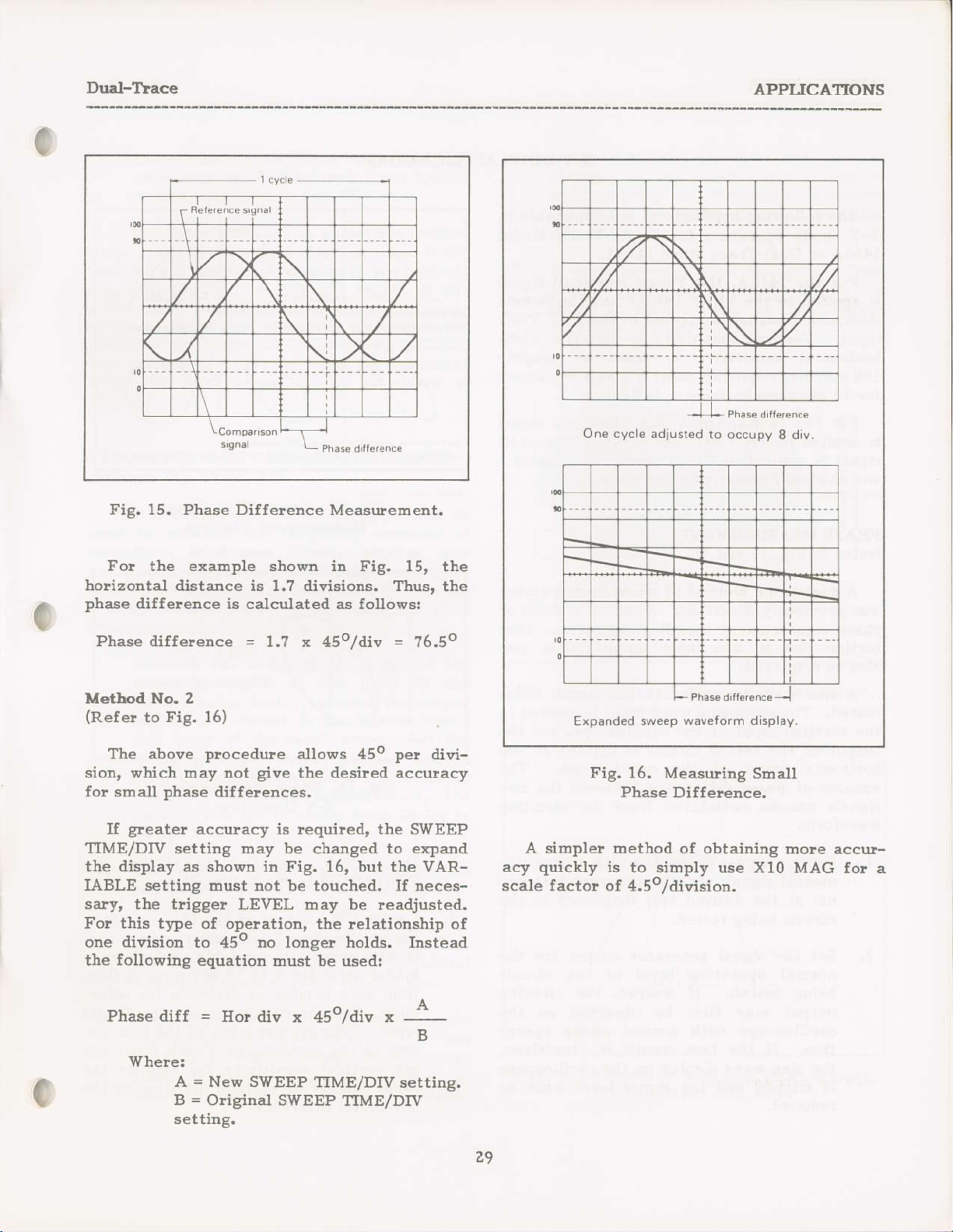
e
DuEl-llace
APPLICAfiONS
0
Fig. 15. Phase Difference MeasrEeEent.
Fo! the example
horizontal
phase
Phase difference
Metbod No. 2
(Refer
The above
sion, which l]1ay not
fo! small
greater
If
TIME/DrV
the display as
IABLE setting
sart
For this t]?e of
one divisioD
foUowing
the
distance is 1.? divisions. Thus, the
differeDce is calculated as follows!
Fig,
to
the trigge! LEVEL tnay be readjusted.
16)
procedure
phase
differe[ces.
accuracy is lequiled, the SUTEEP
setting oay
shown in Fig. 16, but the
Eust not be touched. If neces-
to 45o no loDger holds. Instead
equation
shown iD Fig. 15, the
=
1.7 x 45o
allows 45o
give
the dlesired accuraqy
be
operation, the relationship oI
Eust be used!
/div
changed
=
16.50
per
divi-
to expand
VAR-
One cyc e adjlsred
Expanded sweep
Fig. 16.
Phase Difference.
A simple! Eethod of obtaining
quickly
acy
scale factor of 4.5oldivision.
is
to siroply use X10 MAG
to occupy
waveform d splay.
Measuling Small
8 d,v.
Brore accur-
for a
c
Phase diff
'w
he!e:
A = New
B = Oliginal
setting.
=
Ho! div
x aSolai*,
SWEEP TIME/DrV
SWEEP TIME/DIV
-L
*
settirg.
29
Page 34

APPITCAIIONS
X-Y MODE
X-Y Mode
l^
APPIICATIONS
The fouowing applications are applicable
X-Y fiode operation for Single-Trace Model
1466A o! Dual-Trace Mode
FoI the 1466A, the Y-axis
is applied to the VERT INPUT and the X-axis
(horizontal)
input,
horizoDtal sensitivity
100 mv/div, rcquiring about
for l0 divisions holizontal deflection.
For the 14?6A,
is applied
sighal is applied to CH Z. Both the
and channel 2 sensitiqity are variable.
PEASE MEASUREME}IIS
(refe!
was
phase
toltion due to non-lin€ar amplification
also be displayed.
tested. The same sine wave input is applied
the veltical input of tie oscilloscope, and the
output of the tested cilcuit is aFplied to
holizortal input
ariount of
signals can
to Fig. 17
A dual-trace hethod of
pleviously
measulet:1ent uses
A sine wave is applied to the circuit being
signal is applied to the EXT TRIG
Vertical
to CH 1 and the X-axis
phase
sensitivity is va.riable, while
the
arld 18)
desclibed. A second method of
of the oscilloscope. The
difference between
be
caluclated flolrl the resulting
14?64.
(veltical)
is fixed at loughly
a 1 volt
Y-axis
{veltical)
phase
X-Y
rneasuternent
operation. Dis-
signal
signal
I,.-p
signal
(horizontal)
channel
the two
can
the
to
to
/l/
Noamp rde d s'on,on
Noanpnudeiraro4'oni AhpftudedGronon
1
Fig. 18. Phase Measurement,
lamplrude
no
i
to
Fig. 17. TyPical X-Y
Measurerhent Displays.
X-Y
vu or
o,o%
r
Operation.
daroiton
phale
"
stNE 0
WhereC. Phase
r30
o
o.rd..4"
lqo
Phase
.;
;
6nqle
1. Using a signal
usoidal signal, apply a sine wave test signal at the desired test frequency to the
cilcuit being
Set t}le signal
normal opelating
being tested. If desired,
output may firsi be obselved on
oscilloscope
tion. If
the sin€ \pave display
is clipped and the signal
!educed.
generator
tested.
genelato!
level of the circuit
\rith nolEal sweep opela-
the test cilcuit is overilriven,
with a
output
the cilcuit's
on the oscilloscope
level must be
pure
for
sin-
the
the
30
Select X-Y
TRIG MODE in the X-Y
Connect the output
the oscillGcope
izontal
model
tion; note number
ence. TeDporarily disconnect
input. Connect the input
cuit to the oscilloscope Y-axis
set veltical sedsitivity for
salhe numbe!
horizontal refe!ence.
sensitivity
only) to! 5 to 10 divisions
opelation by
of the test cilcuit
X-axis
(variable
of divisions lor !efe!-
of vertical divisions as tbe
placing
position.
input a.ndl set ho!-
or dual-trace
of the test ci!-
the
to
deflec-
the X-axis
itput ajld
exactly the
U
Page 35

X-Y Mode
APPLICATIONS
0
5. Leave the Y-axis input
reconnect the
results
If
the two signals are in
scope trace is a straight diagonal line. If the
veltical and holizontd
adjusted, this lide is at a 45o angle. A
phase
pattern.
ploduces
The aErormt o!
from the oscilloscope display as
Fig. 18.
FREQI'ENCY
(lefer
used to Eea6ure
aEplifiels, band
works,
ment needed
B & X-Pr€cision Model
Sweep/Function
shift
to Fig. 19
The X-Y llode of this oscilloscope Eay be
are shown
produces
Phase shift of leBs
an elliptical oscilloscope
RESPONSE 1dEASI]REMENIS
etc. The only additional test equip-
is a sweep
X-axis
in Fig. 17.
sensitivity are
a circular oscilloscope
phase
and
Gene!ato!.
shift can be
20)
flequency
the
pass
filters,
geDelato!,
3020, 3025,
connected and
input. Some t]'pical
phase,
(or
more) than
coupling
oscillo-
the
ploperly
90o
90"
pattern.
calculated
shorrD i1
regponse of
net-
such as the
o!
3030
frequencies at the left side of
display. If the
positive-going
the higher frequencies
side of the display.
A detnodulato!
5.
book" tlequency lesponse display as
shown in Fig.
operation beyond 10 MIIZ.
rrlttlttttl
20K 1aK 16K 14K 12K
sweep ramp voltage is
as flequency incleases,
are at the light
plobe
20, ard can a.lso extend
toK 8K 6K 4K 2K
will
give
20
the
a'text
-12
3E
-t8EE
EE
1.
Connect the
sweep
circuit under test.
of the test circuit to the Y-axis
cal) input of the oscilloscope. Set the
sweep
band of flequencies. Fo! a typical audio
f!€quency
generator
generator
genelato!
audio
response oeasulement, the
is set to sweep flou 20 IIz to
o! rf output of the
the input
to
Connect
to sweep the desiled
the
Connect tbe s\reep larnp voltage of tbe
sweep
generator
to the
X-axis
tal) i[put of the oscilloscope.
Set
the TRIGCER MODE switch to X-Y
and adjust the veltical and horizo:ital
seBsitivity Jo! a suitable viewing size.
A standard
ope display such
plobe
will result itr an envel-
as showD in Fig. 19. The
exahple i! Fig. 19 resrdts flol! a negative-going sweep
flequency increaeea,
lamp voltage as
with the higher
of the
output
(verti-
{horizotr-
Fig. 19.
Frequency ReE onse MeasureBent,
Envelope Response.
t-'
L,^,.,.
Fig. 20. Frcquency Response Measurement,
Derlrodulated
ResDonre.
Page 36
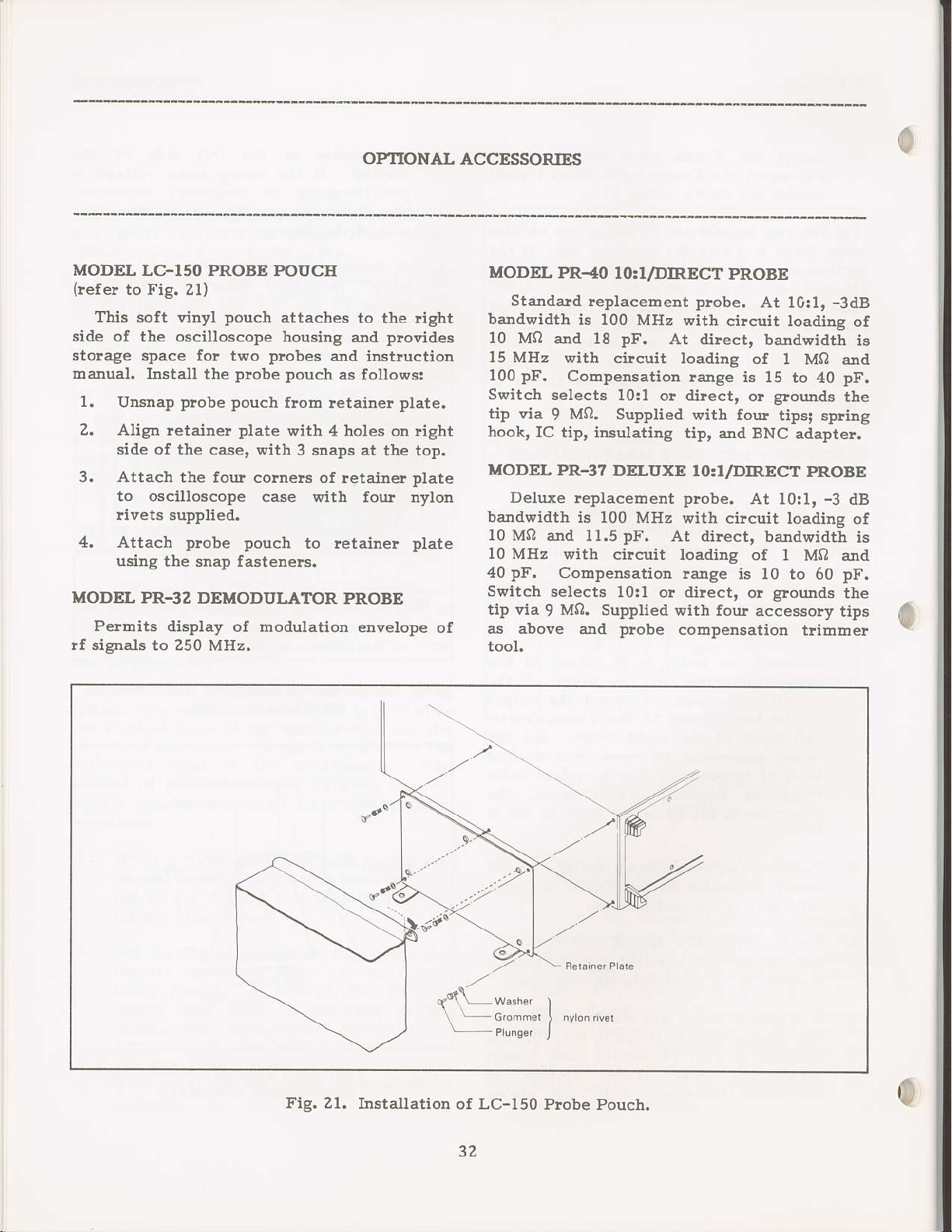
OPIIONAL
il
ACCESSORIFS
MODEL
(!efe!
Tlis soft vinyl
side
storage space fo!
ha.Ilual.
1,
2, Align letaine!
3. Attach the
4. Attach
MODEL
PelEnits
!r slpnals to z5u Mttz.
LC-150 PROBB POUCE
to Fig. 2l)
pouch
of the oscilloscope
two
Install the
Unsnap
side of tie
to oscilloscope
!ivets supplied.
using
plobe pouch
case, with 3 snaps at
four cornels of retaine!
plobe
the snap fastenels.
PR-32 DEMODI'LATOR
display of
attaches to the
housing anal
probes
probe pouch
plate
case with lour nylon
pouch
modulation envelope
and instruction
as follows:
from
retaider
with 4 holes
retainer plate
to
PROBE
the top.
tight
ploeides
plate.
dght
on
plate
of
MODEL
Standald
bandwidth
l0 MQ
15 MHz
100
Switch selects
tip via
hook,
MODEL PR-3?
Deluxe replacemeEt probe,
bandwidth is 100
10 MQ and
10 MHz with
pF.
40
Switch
tip via I
as
PR-40
and 18
with circuit Ioading
pF.
Compensation
9
IC tip,
Conpensation range
selects 10:1 or direct,
MO. Supplied with
-above
Io.1/DIRECT
replacerrent
is 100 MHz with
pF,
10:1 or direct,
M0. Supplied with
insulating tip, and
DELUXE I0:I/DIRECT
MHz with circuit
l1,5pF. At dilect,
circuit loading
and prcbe
At dilect, bardwidti
PROBE
probe.
lange is
compensation
At
circuit loadine
oi
15 to 40
glorijlds
o!
four
BNC adapter.
At
bandwidt-h
of 1 M0 ard
is 10 to 60
glounds
o!
four accessory
-3dB
l0:1,
of
I Mn and
pF.
tbe
tipsi spling
PROBE
-3
l0:1,
loadins of
tlimDel
dB
pF.
the
tips
is
is
1?
Fig,21.
Installation of LC-l50
Prcbe Pouch.
0
Page 37

c
MAINTENAIiICE
W/.RMNG
The
folloving
qucll/ted
awtd electficol
instructlons
servlce
shoclg do not
oJty senticlng other
operutlng
q.&Iified
High
wltQge up to
u,hen
owrctlng,
moy
instmctions
to do so.
coyera are rcmoyd
Rememtur that hlgh
be reteind Inaleflnttely
wttage cq.Wcltors.
oc
ltne wltoge is
inp.rt
pluggd
off.
cfrcuits ony
into
UnpW the
chorge high
petf
orming
servtce
present
ttme
ar oc
\eltage capactto'tr-
F.USE RTPI.ACEMENT
If
the fuse blows,
a.Ird
the oscilloscope
fuae should not
has developed
and
correct
teplace
ratidgi
o! 0.5 aEp
fuse is located
the cause of the
only
with a fuse of the
0.8 at1lp
for 220
DotEally open
in
on
the
the unit. Tty to detelmine
for 100 o! 120 volt
or 240 ?olt opelation.
the reai
o't?
Wrcormel
for
qrly.
ttse
W
To
perform
thon contotned
tztless
21000 wlts ls
ttr the
lr'ou
present
or€
atld the tmlt
yoltsge
q
high
remember
ALso
t'].e
on tine
inrtrumgnt
that
\roltdge
outlet, e\ren lf tumed
oscilloscop€ @rd
dls-
beforc
pwcadures,
pilot
light \rill go
will not operate,
unless a
blown fuse,
prope!
panel
(see
probleD
current
operation
Fig. 2).
is
is
out
The
then
The
PERIODrc
Scre\rihiver adjustEents
checked and
coEpensation,
adjustEents
Ptocedutes
Prcbe CoElrcusati@
1,
tlace rnodel.
plobe).
2. Touch
inal.
Adjust oscilloscope
3
at 5 or 6
Adjust
for
overshoot,
to Fig. 22.
ADJuSTMENTS
adjusted peliodicaUy.
tlace rotation,
are included
giveD
aie
Comect
(CH
or
ptobes
1 aid
4 cycles of PROBE
optiEuE
CH Z INPUT
Repeat
tip of
probe
divisionE a4plitude.
coDpensation
lounding
below.
squale wave
ot y need
and astigEatisE
in
to VERT
jacks
plocedute
to PROBE
controls
ADJ
ttimEer
off, and
this
cat€goly.
INPUT
for
to! each
ADJ terh-
to display
squaie wave
otr
(tliniouE
tilt). Refer
to be
probe
iack.
iuat-
plobe
CASE
the
frou
bandle. The
slightly
panel
Ually le|Doved by
(two
reEoved)
REMOVAL
To redrove
nine
each side)
rDdet the lip
bezel. The bottorD
additional at
the top
screw6
ald lilt
flont
aDd lifting off
cover,
(tbree
ol the top
forroed by
removing
sides if
tbe bottoE
siEply lerlove
froD
off the cover by
top and
cover slides
the frcdt
cove! tiay be
the tbree
top cove!
screws
cover,
tbtee
is not
tbe
siD-
33
Fig.
ZZ. hobe
Coopensation
Adjustrnent.
Page 38

MATNTENANCE
Tlace Rotation AaljustEedt
l. Set oscilloscope controls fo!
trace display, and with the AC-GND-DC
switch
2. Use the veltical POSnON contrcl to
position
holizontal line on the
The
th€
3. Use the TRACE ROTATION adjustment
on th€ flont
tilt.
AFtiSbatish
1. Set the TRIG MODE switch to X-Y and
AC-GND-DC switch(es) to
will
Z. lgith INTENSITY set about
adjust both
trols fo! the shatpest, loundest spot. Do
not leadjust
(Neve!
lianc€ to remain
fo! more than a few seconds. The scleen
may be
set to GND.
the trace ove! the center
graticule
trace 6hould
horizortal
ArljustE€nt
ploduce
allow a sl]|a.ll spot of high b!il-
permanently
be
eractly
line.
panel
a spot on the screen.
the
to eliDinate
ASTIG
ASTIG aJte! this step.
stationary on the scleen
and FOCUS coll-
burnedJ
a single-
parallel
any
GND.
Did-range,
scale.
with
tlace
This
at 0.1 V/div sensitivity
di!ect). With
be five divsions
sensitivity. The VARIABLE
set to CAL duling
fo! cha.nnel 1 and
hodeI.
The PROBE
general
a
a signol
plobe
this check. Repeat check
ADJ stgnal moy b€ uaed only os
check of colibrution occuracy, not
so&rce
for
odiustments; o srgnol
(with
set for
aEplitude at 10 mv/div
channel 2 on dua.I-tlace
perfotming
source of t 0.5qo or
better dccuracy ls r€quired
ddiu.stm
ents.
probe
10!1, there should
contlol E|ust be
set for
rccalibration
callbratlon
for
INSTRUMENT REPAIR SERVICE
Because of the specialized
equipment requiled
caliblation, Eany custorDers
upon
maintain
ized service agencies for this
thi6 selvice, even if the oscilloscope
longer rmder
given
TION
inal charge fo! instlurrents out of warranty.
B & K-Precisid for this
a detwork of B & K-hecisioD
wallanty, follow the instluctions
in the ISARRANTY
portiorl
of this rtanual. There is a nom-
for instruEent fepai! and
skills and test
prefe!
selvice, We
purpo6e.
SERVICE INSTRUC-
to tely
author-
To
os
use
is ao
I
a
g
CAIJBRATION CfiECK
genelal
A
be
Eay
PROBE ADJ
telminal
(within
displayed wavefolE amplitude
made by displaying the output of the
J
check
telminal
plovides
6%). This signal should
of
calibration accuract
on the scleen.
a squale wave of 0.5 V
of
ploduce
five
This
p-p
divisions
ADDITIONAL SERVICING INFORMATION
A cohplete selvice manual
aeailable fo! the Model 1466A ajld
Oscilloscopes. Requests
manual should be sent
Service Depattoent address listed in
a
}iTARRANTY
sure to sDecifv Model
SERVICE INSTRUCTIONS. Be
to the B & K-hecfuid
arrd setial nuEber.
for tbe selvice
34
will soo[ be
14?6A
the
Page 39

WARRANTY
(For
U.S.A. ond its Overseos Territories)
SERVICE INSTRUCTIONS
1, Refe!
adjustments that may be applicable.
2,
If the
pack
describing t}te
(UPS
list enclosedl with unit).
your
If
distlibuto! fo! the name of
to the MAINTENANCE section of
above-mentioned does not correct
it seculely
preferred
list of
autlolized
(pleferably
probleEr
in U.S.AJ to the nearest
in the oliginal carton o! double-packed). Enclose
and include
B & K-Precisioat
your
[earest service agency, or write to:
your
selvice agencies
your
problem you
the
name and address. Delive!
B & K-Precision
B & K-Precision, Dyncscon
Fcctory
4050 Nor+h
Service Operoiions
Rovenswood
Chicogo, lllinois 605
(312)
Tel
327-7270
Telex:25-3475
Also use this address for tecbnical inquiries and replacement
LIMITED ONE-YEAR WARRANry
DYNASCAN CORPORATION warlants to the original
ploduct,
Eaterials
and tle component
peliod
fo!
a
of one
parts
yea!
thereof, vfu be free flom defects in
floE
the date of
purchase.
B & K-Precision
are expeliencing with
authorized
has
been misplaced, contact
Corporotion
Avenue
l3
purchasel
instluction
to, or ship PREPAID
service agency
parts
that its
orders.
B & K-Precision
wolkmarship a$d
manual fo!
your
unit,
a letter
(see
your
DYNASCAN wiu, without charge, Iepai! or replace, at its option, defective
co&lonent
factoly
receipt.
?o obtain {rarranty
mailing the enclosed
Coltland Street, Chicago, nlinois 60635 within fifteen
ErcluJronsi this vcrronty does not opply
rcsult of
parts
service
upon delivery to all autholized B
department, accompanied by
covelage in tle U.S.A., this
wa}ranty registlation card to
unduthorizd alterotlorrs
repoirs.
or
selvice contractor or the
date in the
B &
K-Precision,
proof
of
product
{15)
trr the e\ent
& K-Precision
pulchase
the
must be registered by cofipleting and
DYNASCAN,
days from the date of
of
misuse or ab,6e of the
It is rroid if the senol twmber is altered,
product
folm of a sales
6460 West
pu}chase.
prcduct
or as a
defaced or
o!
remoted.
DYNASCAN
damages lesu.lti[g from loss of use. SoEre states do not allow limitation of
consequential damages, so the above limitation
This
warlanty
state to state.
you!
Fo!
authodzed
selvice cannot be obtained locally,
4050 North Ravenswood Avenue, Chicago, nlinois
shipD
(
teldtolies. In
seIls,
ent.
B & K-Precision Test Instluments warrants
convenience we suggest
to make lepairs oI can lefer
othet coudtlies, each dist buto? watlants the B & K-Precision
not
shall
gives you
be liable
specific lights and
for
any consequential damages, including without limitation
you
please
o! exclusion may not apply to
you
lnay also have othe!
contact
you
send the unit to B
your
B & K-Precisiotr
to the nearest
60613,
ploducts
ploperly packaged
sold only in the
sereice contractor. If warranty
& K-Precision
iDcidental o!
you.
rights shich vary from
distlibutor,
Service Department,
to avoid damage in
U.S,A, and its overseas
who lnay be
ploducts
wlich
it
45511 PRTNTED lN JAPAN B5O 7505 00
o
(G)
Page 40

trlYNASCAN
COF|PTORATION
6460 West
Chicago,
Cortland Street
lllinois
60635
480-378-9'001
 Loading...