

Page 1
v
SMHz
OSCILLOSCOPE
f
{t
K'
Page 2

IEST
INSTRUTUENT
SAFETY
WARNIilG
\,
Normal
amount
exposed
through the
should
eertain
more easily
praetiees
away
eantly
1, High
2.
3. If
use of test equipment
of
high voltage
be eonsidered
eonditions.
thCt
from
reduee the
voltage up to 1r400
high voltage
that
a
anode
and
removing
Dontt
sary.
Diseharge
possible,
high voltage
points
and servieing
danger from eleetrieal
present.
is
heart
produee
your
high
expose
in defeetive
will stop
dangerous and
Higher
iethal eurrent.
a
prevent
will
nealt
eap.
power.
Turn
high-voltage eapaeitors
familiarize
in
ease of aeeidental
faetor if
risk
preeautions
voltage
high
off
points.
eharge
-Discharge
voltage
equipment
However,
equipment.
An
human heartbeats.
most
voltage
eontaet
you
volts
when the
may be retained
needlessly.
yourself
of
shoek
eleetrieal
poses
know and
is
high voltage
while
beeause
shock
hazardous sinee
even
an
Your normal
exposed
with
eontaet
observe
present
is operating
unit
Remove
making
removing
after
equipment
the
with
remember
test equipment
testing
eausing
Voltage
greater
work
high voltage,
servieing
when
indefinitely,
eapaeitors
test eonneetions
high voltage
that
must often
10
as
it
with a
the
housings and
produee
ean
threat
habits should
high
following
with
with
power.
being
exposes
be
milliamps
low as
and
this
the
espeeially
a
tested
35
lethal
a
beeause
that
voltage.
safety
oseilloseope.
removed.
ease
grounded
eovers
high-voltage
in
and the
may appear
you
to a
performed
of eurrent
de or
volts
eument
voltage
sueh
inelude all
steer eurrent
will
You
will
preeautions:
Observe
Remember
CRT
the
at
test
when
only
loeation
unexpeeted
at
eertain
where
pass
to
ae rms
under
ean
aeeepted
signifi-
soeket
after
lead
neees-
eireuits.
of
all
its
4.
Use
insulated
are
5. Use the
probe.
provide
When using the oseilloseope, the
6.
ehassis
ground
hazard.
1.
When using a
portion.
8. When testing ae
on some
any
off.
insulated floor
an
surfaee on whieh
work
damp
not
Be
and
wire eonneetion or
time the equipment
or wet.
time-proven
partieularly
good ground
a
housing of
probe,
powered
power
input eireuits sueh as
rfone
return
toueh only
material or a
hand in the
eareful
the
is
eontinued
to
path.
oseillos-eope
float the oseilloseope;
equipment,
eonneeted
large,
plaee
to
poeketn
avoid
ground
at
the insulated
remember
the
to an
inside baek
on
insulated
equipment;
teehnique
eontaeting
of the
wire
portion.
outlet,
ae
ground.
that ae
switeh,
eover
earth
on-off
floor
make
and
while
nearby
a
3-wire
Do
to do so
Never
line
fuses,
even
mat to stand
eertain sueh
handling an
metal
ae
not attempt
may
voltage
power
the equipment
if
objeet
power
pose
toueh
the exposed
is usually
transformer,
plug
a
and an
on,
surfaees
instrument
that eould
pla_ees
defeat the
to
great
safety
present
turned
is
the
tip
ete.
v
Page 3
v
SERVICE
MANUAL
for
B
MODEL
SMHz
fhis senrice manual is intended
only. To
qnlified
I}
High voltage of
ment is operating.
whenever
is
turned off. Observe all high
is removed from
result in fatal
avoid electric shoclg do not
to do so.
approximately 1,400
AC line voltage is
the
power
ae
the oseilloseope.
eleetrie shoek.
eord is eonneeted to a live
K-PRECISION
&
14O3A and
1 4O5
OSCILLOSCOPE
WARlrllNG
use by
for
voltage
Contaeting
qwlifi.ed
perform
volts de
present
safety
preeautions
electronfcs technfcians
senlicing
present
is
on the input
outlet,
exposed
urless
when
even
when
high voltage eould
you
this instru-
power
eireuits
if the seope
housing
the
are
{lF
K'
tulA€
6470 W. Contland
Telephone
use this
-
address
for
teehnieal inquiries
luTERm,ATtotuAt coRP.
|
St. . Chicago,
2) 889-1 448
[31
and
lL
replaeement
60635
parts
orders
Page 4
TABLE
TESTINSTRUMENTSAFETY
OF
o o o... o
CONTENTS
r.....
r o..
o..inside
front
v
Page
eover
INTRODUCTION
SPECIFICATIONS..
CONTROTS
CIRCUIT
ADJUSTMENTS ..
MAINTENANCEo
TROUBLESHOOIjNG... o....... r r.
PARTS IJST.
VOLTAGE
CIRCUITBOARD
SCHEMATIC DIAGRAM o... o r........
HISTORY
DESCRIPTION........... .......
CHART.... r o... r...
OF
.......
o........ o....
INDICATORS. r... r
AND
o I o. o.. o.. o........
o. r. o o. r
r . . . .
. . . . . . r r o . . . I
MAP.
PRODUCTTON CHANGES...
r.... o r..,
r. o.. r. r..
o
r...
o o.'. r.
'.
o..
r . . . .
r o r r.
o. a r....
r..
r. r..... o o..
o.
r. o o o. r o......
.... o o. o...
r o o o t. !.......
o o o r.. o r o. t.
o r
r.....
o..
o...... . r r.......
o . . o . | . . ] . .
o....
o..........
T
r o..... o.......
o. o.. o o.....
r o. o.,.......
o. o o..
o.....
r. o r....3
o. o.....
. o . t .
r.......
t.....
o. r.
t......1
...2
...
o. o.
. . . .
13
1?
20
24
.29
30
o.....
o...31
o ..32
ti
Y,
SERVICE
HINTTI
o..... r... r
...
BEFEBBN CE
Model 1403A
Instruetion
Modell40SASehematie
Model 1405
Model
Instruetion
1405Sehematie
Manual
Diagram &
Manual
Diagram & PartsList ...o...
' ' r r...
PI'BIICATIONS
o . . . . .
PartsList .
o... t.....
o..
o..........
r r..
. . . . . . . . . o . o
.
o o.......
o. o.... .
o o. o
33
o..
r.
480-17?-9-001
.
499-085-9-001
480-26?-9-001
499-164-9-001
v
Page 5
v
INTRODUClTON
SCOPE
This
Model
through
It also
produetion
manual.
the
loose
The
tion,
produetion
and repair of
DESCRTPIION
f
The B & K-Preeision
Oseilloseopes
general
waveforms.
round
whieh
viewed
also featues
divisions
The vertieal
to 5 M
Input
value
uator
variable
waveform
vided
frIANUAL
OF
serviee manual
1403A
the
Produetion
printing
ttAddendumrt
"History
at the rear
purpose
CRT with a 12 x tZ
overlays
on about 8 x 10
amplitude
Hz,
impedanee
for
offers 1:1, 10:1
gain
allow
to
from
end of
eovers Model
until
of this manual
ehanges
the instruments.
OF EQUTPMENT
are
These
a dB
ehannel has
and
sensitivity of 10
oseilloseopes.
eontrol
amplitude.
external
the start of
produetion.
the
ehanges
sheets.
of Produetion
of
the marrual,
whieh
eompaet,
instruments
oseilloseopes
the
CRT.
seale, refereneed
equals
is 1 Megohm,
eovers
1405
printing
Model 1403A
divisions.
and 100:1
offers fully
Terminals
B & K-Preeision
from
of this
whieh oeeur after
will be
Changes"
may
affeet servieing
single
for observing
division
Waveforms
The
0 dB.
bandwidth
a
A three-step
signals to be
produetion
start
the
eovered by
itemizes all
and
use a 3-ineh
gratieule
gratieule
mV/division.
the standard
steps,
adjustable
are
also
of
serviee
see-
1405
traee,
ean be
to
six
of de
atten-
plus
a
pro-
applied
direetly to
the
CRT.
The horizontal
sweep,
to
span the 10
be synehronized
ean
observed
tivity of
available, with
peak.
X-Y
In
beeomes a variable
m aximum
Bandwidth is up to 250 kHz.
provided
DIFFERENCES
1405
AND
Eleetrieally, the
nearly identieal.
hardware
The Model 1405
Model
ease eolor,
the
in
m
EXCLUSTON
1403.
in funetion
major
ieations.
1403A
front
the
anual.
This
Although the Model 1403 has
differenees
the vertieal
ehannel uses
with four
(internal
1 division.
operation, the
sensitivity
for
and meehanieal
panel.
rrParts
serviee manual does not
ranges
Hz to
syne) with a
a sensitivity of 2
gain
intensity
BETWEEN
Model 1403A
However,
beeame a replaeement
in
19?9,
and many eosmetie differenees on
All differenees
Listn seetion of this
mODEL 1403
OF
to
Model 1403A, there
in eireuit design and speeif-
defleetion
and
100 kHz
to
the
External
X-axis
of 300
modulation, if desired.
parts
featured
and
plates
reeurrent
variable
a
band. The
waveform being
trigger
syne
volts
horizontal
amplifier with
mV
A Z-axis
ITIODEI.S 1403A
and
almost
are different.
are itemized
eontrol
sweep
sensi-
is also
peak-to-
ehannel
per
division.
input is
1405
all external
for the
different
a
serviee
eover
Model
a similarity
are
several
of
type
are
rl7
Page 6
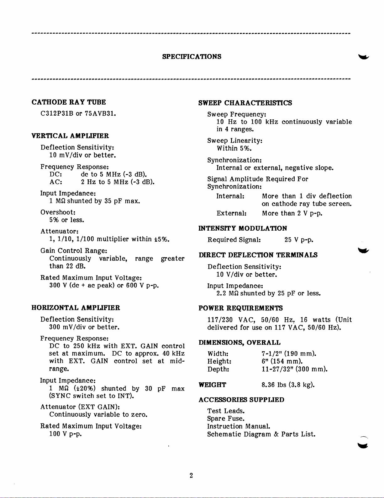
SPECIFICATIONS
Y/
CATHODE BAY
C3L2P31B or 75AV831.
VERTICAL
Defleetion
10
mV/div
Frequeney
DC:
AC: 2 Hz
Input
Impedanee:
1 MO
shunted by
Overshoot:
5% or less.
Attenuator:
t, 1-/L0,
Gain Control Range:
Continuously
than 22
Rated Max,imum
300
V
TUBE
AMPIIFTER
Sensitivity:
better.
or
Response:
de to
1/100 multiplier
dB.
Input Voltage:
(de
+
ae
35
(-3
pF
max.
or 600
5 MHz
to 5 MHz
variable,
peak)
Og).
(-3
dB).
within
range
p-p.
V
t596.
greater
SWEEP CHARACITRISTICS
Sweep
Sweep Linearity:
Synehronization:
Signal Amplitude Required For
Synehronization:
INTENSITY IIIODULAIION
Required
DIBECT DEFLECTION
Defl eetion
Input Impedanee:
Frequeney:
10 Hz
in 4 ranges.
Within
Internal
Internal: More than 1 div defleetion
External:
10 V/div
2.2 MQ
100 kHz
to
5%.
or external,
on eathode ray
More
Signalz
Sensitivity:
or better.
shunted
by 25
eontinuously
negative
than 2 V
25
TERMINATS
pF
p-p.
p-p.
V
or less.
variable
slope.
tube
sereen.
V
HORIZONTAL
Defleetion
300 mV/div
Frequeney
DC
to 250 kHz
set
with
range.
Input
1
(SYNC
Attenuator
Continuously
Rated
100
maximum.
at
EXT.
Impedanee:
(120%)
M0
switeh
Maximum
p-p.
V
AfrTPLIFIER
Sensitivity:
or better.
Response3
with
GAIN
shunted by
to
set
(nXt
GAIN):
variable to zero.
Input
EXT. GAIN eontrol
DC to
eontrol
INT).
Voltage:
approx.
set at
30
40
pF
kHz
mid-
max
POWER
delivered for
DIUENSIONS,
Width: 7
Height: 6o
Depth:
WEIGIIT
ACCEf|SORIES SUPPLIED
Test Leads.
Spare
Instruetion
Sehematie
RBQIIIREMENTS
Ll?
/230
VAC, 50/60 Hz,
Fuse.
use on
OVERALL
Manual.
Diagram &
117
-L/2"
(154
IL-27
8.36 lbs
/32n
VAC,
(1gO
mm),
(300
(3.8
Parts
16 watts
50/60 Hz).
mm).
mm).
kg).
List.
(Unit
^.
v
Page 7

v
CONTROIS AND
INDICATORS
BOTTOM
@ @ @rnoruTpANELO)
@
PANEL
l8ffE
sreec,.eer6s1r.y
I
Z
axrS
rNPut
crr9
2t
v
otq
REAR
PANEL
i*tr?F
l-5'{-r
L,mn,,,J
;''6':
-
FRONT
PANEL
INDICATORS
1.
Neon
Pilot
operating.
2.
POWER
3.
EXT SYNC/HOR
external syne or
signal.
adjaeent
4.
+
Jaek
Fig. 1. Model 1405
CONTROIS
Lamp.
Lights
Switetu Power
INPUT
external
Conneet
ground
Earth
signal eom mon to
terminal.
and ehassis
AND
when
seope
ON-OFF switeh.
Jaek
Input
horizontal
ground.
Controls And Indieators.
VERT
5.
INPUT
signal
adjaeent
is
AC-DC
vertieal input
vertieal
and, therefore, de
for
bloeked,
eomponent only.
the
input
is direetly
allows both de and ae eomponents of
signal
to eause vertieal defleetion.
Jaelc
Input
for vertieal
Conneet signal eommon to the
ground
Switetr. Seleetor
input
permitting
jaek.
switeh
eoupling. In AC
position,
is eapaeitively eoupled
eomponent of signal
observation of ae
position,
DC
In
eoupled and,
vertieal
therefore,
for
is
It
Page 8
CONTROI,SI
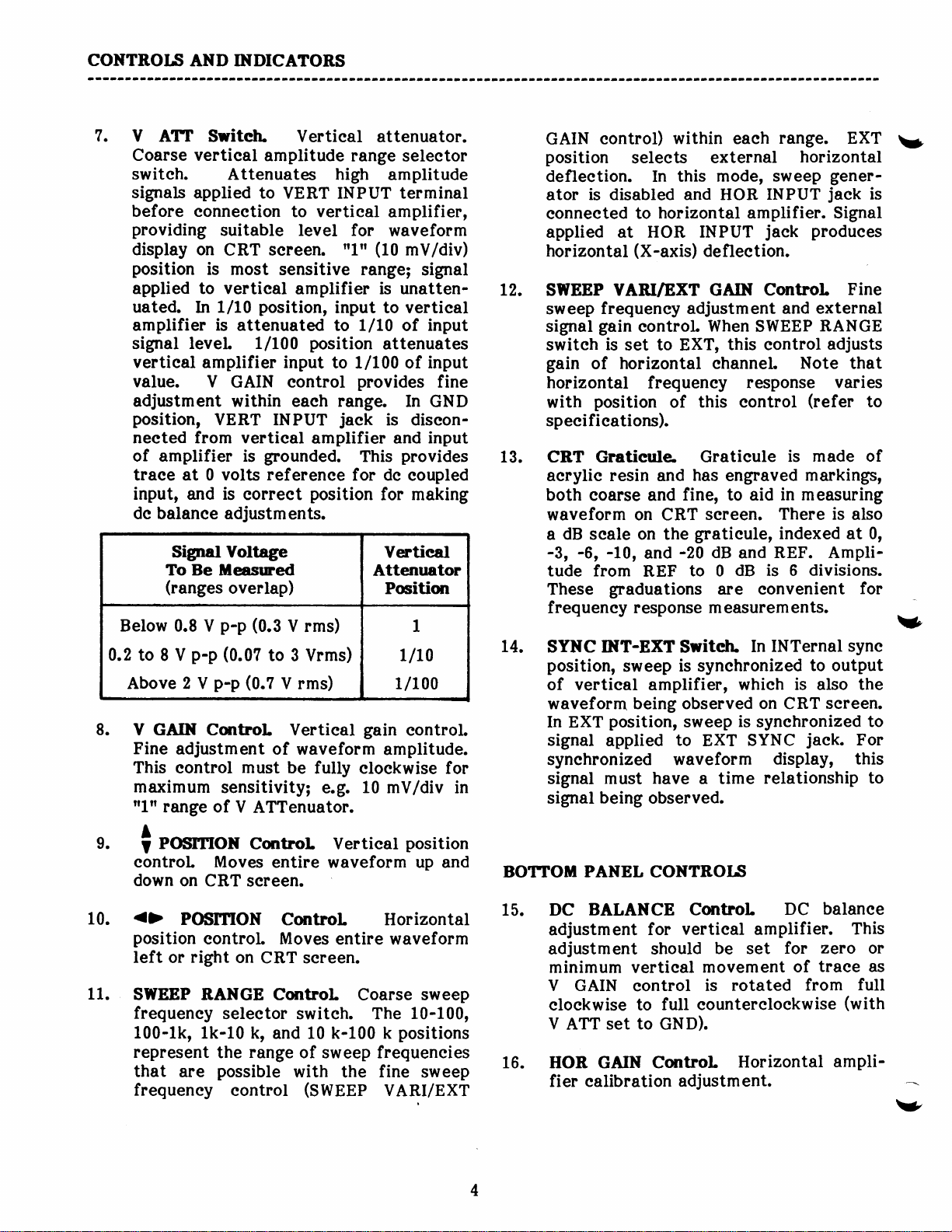
7.
V
Coarse vertieal
switeh.
signals applied
before eonneetion
providing
display
position
applied to vertieal
uated.
amplifier
signal
vertieal amplifier input
value.
adjustment
position,
neeted from vertieal
of amplifier is
traee at 0
input, and is
de balanee adjustments.
Below
0.2
to 8 V
AND INDICATOBS
ATT Switeh. Vertieal
amplitude
Attenuates high
to VERT INPUT terminal
suitable level for
on
is most
1/10
In
is
level 1/100
V GAIN eontrol
VERT
volts referenee
Signal Voltage
To Be ileasrned
(ranges
p-p
0.8 V
p-p
sereen.
CRT
position,
attenuated to l/10
within eaeh
INPUT
grounded.
eorreet
overlap)
(0.3
(0.0?
to 3 Vrms)
Above2Vp-p(0.?Vrms)
8.
V GAIN Cmtrol Vertieal
Fine
adjustment
This eontrol
maximum
ftlff
range of
sensitivity;
of
must
V
ATTenuator.
attenuator.
range
to vertieal
n1n
sensitive range;
amplifier is unatten-
input to vertieal
position
to 1/100 of input
range.
jaek
amplifier and input
for de
position
V
rms)
seleetor
amplitude
amplifier,
waveform
(10
mV/div)
signal
of
attenuates
provides
In GND
is diseon-
provides
This
eoupled
for making
Ventieal
Attenuator
Pcition
1
LlLO
1/100
gain
control.
waveform amplitude.
be
fully eloekwise
10
e.g.
mV/div in
input
fine
for
GAIN
position
defleetion. In this
ator
eonneeted
applied at
horizontal
L2.
SWEEP VARI/EXT GAIN
sweep
signal
switeh
gain
horizontal
with
speeifieations).
CRT Gratieule-
13.
aerylie resin and
both eoarse and
waveform on CRT
a
-3, -6,
tude from
These
frequeney response m easurem
L4.
SYNC INT-BXT
position,
of vertieal amplifier,
waveform
In EXT
signal
synehronized waveform
signal m
signal
eontrol)
is
disabled
frequeney adjustment
gain
is
set to EXT,
horizontal ehanneL Note that
of
position
dB seale on
-10,
graduations
sweep
position,
applied
ust
being
within
seleets
and HOR
horizontal amplifier. Signal
to
HOR INPUT
(X-axis)
eontrol
frequeney
of
has
fine, to aid
gratieule,
the
-20
and
to 0
REF
Switeh.
is synehronized
being observed on CRT
sweep
to
have a time
observed.
range. EXT
eaeh
external
mode, sweep
defleetion.
When
this eontrol
response varies
this eontrol
Gratieule
engraved
sereen.
dB
and
dB is 6
are eonvenient
In
whieh is also the
is
EXT SYNC
horizontal
INPUT
jaek
Control
and external
SWEEP
is
in
m easuring
There is
indexed at 0,
REF. Ampli-
ents.
lNTernal syne
synehronized
display, this
relationship
gener-
jaek
is
produees
Fine
RANGE
adjusts
(refer
made of
markitrgs,
divisions.
to output
jaek.
to
also
for
sereen.
to
For
to
Y
v
9.
10.
11.
POSITION
t
eontrol Moves
down
{>
position
left or
SWEBP RANGE
frequeney
100-1k,
represent
that
frequeney
Control Vertieal
entire
on CRT
POSffiON
right
are
sereen.
Control Horizontal
eontrol Moves
on
CRT sereen.
Control Coarse
seleetor switeh. The
1k-10 k,
the
possible
and 10 k-100 k
range
eontrol
of sweep frequeneies
with the
(SWEEP
position
waveform
entire waveform
up and
sweep
10-100,
positions
fine
sweep
VARI/EXT
BOTTOIII
15. DC
16. HOR
PANEL
BALANCE Control
adjustm ent
adjustment should
minimum vertieal
V GAIN
eloekwise
V
ATT set
GAIN
fier ealibration adjustment.
CONTROII;
for
eontrol
to full
to
GND).
Control
balanee
DC
vertieal amplifier.
ze?o
be set
movement
rotated
is
eountereloekwise
for
of
from
Horizontal
traee as
This
or
full
(with
ampli-
v
Page 9

CONTROI^S
INDICATORS!
AND
v
REAR
L7.
18. POCUS Control
19.
20.
2L.
PANEL CONTROTS
INTENSITY ContrcL Adjusts brightness
of traee.
trace.
Z
AXS
,
intensity modulation.
an
ae
25 V
portion
negative
blanks
GND
ground.
V DIB Terminal Direet
terminaL
Adjusts elarity of
Terminal Input
This
voltage
p-p
to blank
of
signal
portion
sereen.
Terminal Earth
pulse
or
the
inereases
reduees
An external
terminal for
jaek
requires
of approximately
sereen.
defleetion input
signal ean be
Positive
intensity, and
intensity or
and ehassis
routed
tion
(eonneet
GND
switeh
division.
DIR-NOR
22.
vertieal deflection
position,
eonneeted to
for
VERT
DIR and GND input
neeted to
23.
CBT AfrJ.
Loosen and rotate
tilt.
Power
24.
direetly
plates
terminal), and setting DIR-NOR
to DIR. Sensitivity
normal
INPUT
Ccd.
to
by
eonneetion
signal
Switeh.
output of
vertieal defleetion
eommon to the adjaeent
vertieal defleetion
oseilloseope operation
jaek.
Tlaee rotation
CRT to eorreet traee
vertieal
CRT
to this terminal
is 10 volts
Seleets
plates.
vertieal
In
input to
DIReet
terminals are eon-
deflee-
per
CRT
NORmal
In
amplifier
plates
using
position,
plates.
adjustment.
is
V
rI'
rt
Page 10
EIRCIITT
DESCRIPNON
v
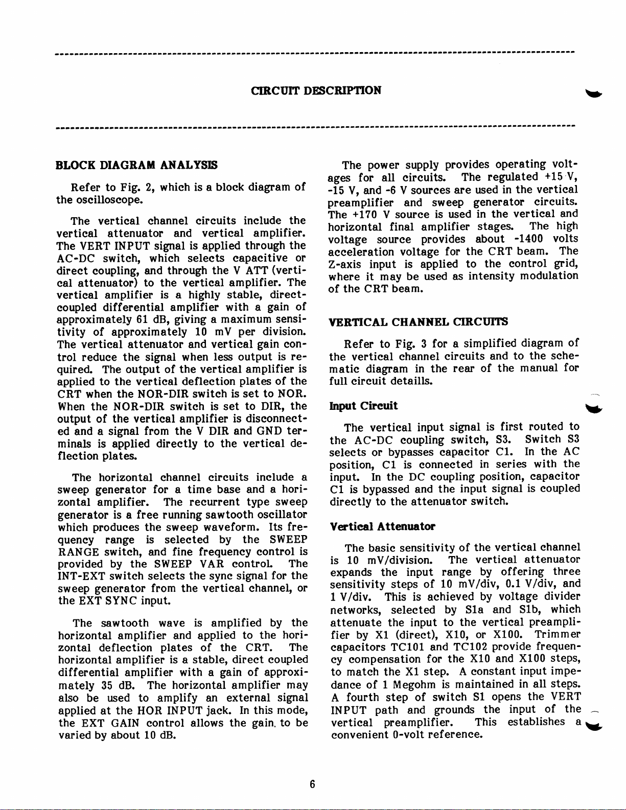
BLOCK DIAGBAM
Refer
the
The
vertieal attenuator
The
AC-DC
direet
eal attenuator)
vertieal amplifier
eoupled
approximately
tivity of approximately
The
trol
quired.
applied
CRT when
When
output of
ed and
minals is applied
fleetion
The
sweep
zontal
generator
whieh
queney
RANGE switeh, and
provided
INT-EXT switeh seleets
sweep
the
The sawtooth
horizontal amplifier and applied
zontal
horizontal
differential
mately 35
also be used to amplify
applied at
the
varied
to Fig.
oseilloseope.
vertieal ehannel
VERT INPUT
switeh,
eoupling,
differential
vertieal attenuator and
reduee the signal when
output of
The
to the
the NOR-DIR
NOR-DIR
the
the vertieal amplifier
a signal
plates.
horizontal ehannel eireuits
generator
amplifier. The
is a
produees
range
by the SWEEP VAR
generator from
EXT SYNC
defleetion
amplifier
amplifier
dB. The
the HOR INPUT
EXT GAIN eontrol
by about
ANALYSXS
2, whieh is a
and vertieal
signal
whieh seleets
Md through
to the vertieal
is a highly stable,
amplifier with
61
vertieal defleetion
from the V DIR and
free
the sweep waveform.
input.
10 dB.
giving
dB,
the vertieal amplifier
switeh is set
direetly to the
for
a time
running sawtooth
is seleeted
fine frequeney eontrol
the
wave
plates
is a stable,
with a
horizontal
bloek diagram
eireuits
is
applied
the V ATT
a maximum
10 mV
vertieal
less output
switeh is
base and
reeurrent type
by the SWEEP
the syne signal
vertieal ehannel,
is
amplified
of the CRT.
gain
an external
jaek.
allows
of
inelude
amplifier.
through
eapaeitive
amplifier.
a
per
gain
plates
set to NOR.
to
diseonneet-
is
GND
vertieal
inelude
oseillator
eontrol
to the
direet eoupled
of approxi-
amplifier
In this
gain.
the
the
the
or
(verti-
The
direet-
gain
of
sensi-
division.
eon-
re-
is
of the
the
DIR,
ter-
de-
hori-
a
sweep
Its fre-
The
the
for
or
the
by
hori-
The
may
signal
mode,
be
to
is
The
ages
-15
V,
preamplifier
+170
thg
horizontal
voltage souree
aeeeleration
Z-axis
where
the CRT
of
YEBIICAL
Refer
vertieal
the
matie
full eireuit
Input Cireuit
The
the
seleets
position,
a
input. In
is
Cl
direetly
Vertieal
is
The
10
is
expands
sensitivity
1
V/div.
networks,
attenuate
fier
eapaeitors
ey eompensation
mateh
to
danee
fourth
A
IN PUT
vertieal
eonvenient
power
for
and
input
it
diagram
vertieal
AC-DC
or
bypassed
basie sensitivity
mV/division.
by
of 1
supply
all eireuits.
-6
V sourees
and sweep
V souree
final amplifier
provides
voltage
is applied
may be
beam.
CHANNEL
to Fig.
detaills.
bypasses eapaeitor
Cl
the
to the attenuator
Attenuator
the
steps of
This is aehieved
seleeted
the input
Xl
TC101
the
Megohm
step
path
preamplifier.
0-volt
used as
3
ehannel
in
input
eoupling
is eonneeted
DC eoupling
and
input
(direet),
Xl step.
of
and
provides
The
are used
generator eireuits.
is used
for
for a
eireuits
the
the
range
10
by S1a and
to
X10,
and
for the
is
switeh
grounds the
referenee.
in the
stages.
about
the CRT
to
intensity
CIRCI'NS
simplified
of the
rear
signal
switeh,
in series
position,
input
switeh.
of the
vertieal
The
by offering
mV/div, 0.1
by
the vertieal
or
TC102
XL() and
eonstant
A
maintained
S1
This establishes
operating
regulated
in the
vertieal
-1400
beam.
eontrol
the
modulation
diagram
to the
and
manual
first
is
53.
Cl.
signal
vertieal
voltage
Slb'
X100. Trimmer
provide
X100
input
in all
opens the
input
volt-
+15
vertieal
high
The
volts
grid'
sehe-
routed
Switeh
In the AC
with
eapaeitor
is eoupled
ehannel
attenuator
three
V/div'
divider
whieh
preampli-
frequen-
steps'
impesteps.
VERT
of
V'
and
The
of
for
to
S3
the
and
the
a
;
v
Page 11
CIRCTITT
DESCRIPTION
v
CRT
V.AMP
Ol01l,0111
SWEEP
NERAT
12.
EXT
EXT SrYrC
I]IPUT
HOR
01
01
13
H.
AMP
0114-Q116
+15V +170V
POWE R
SUPPLY
|}
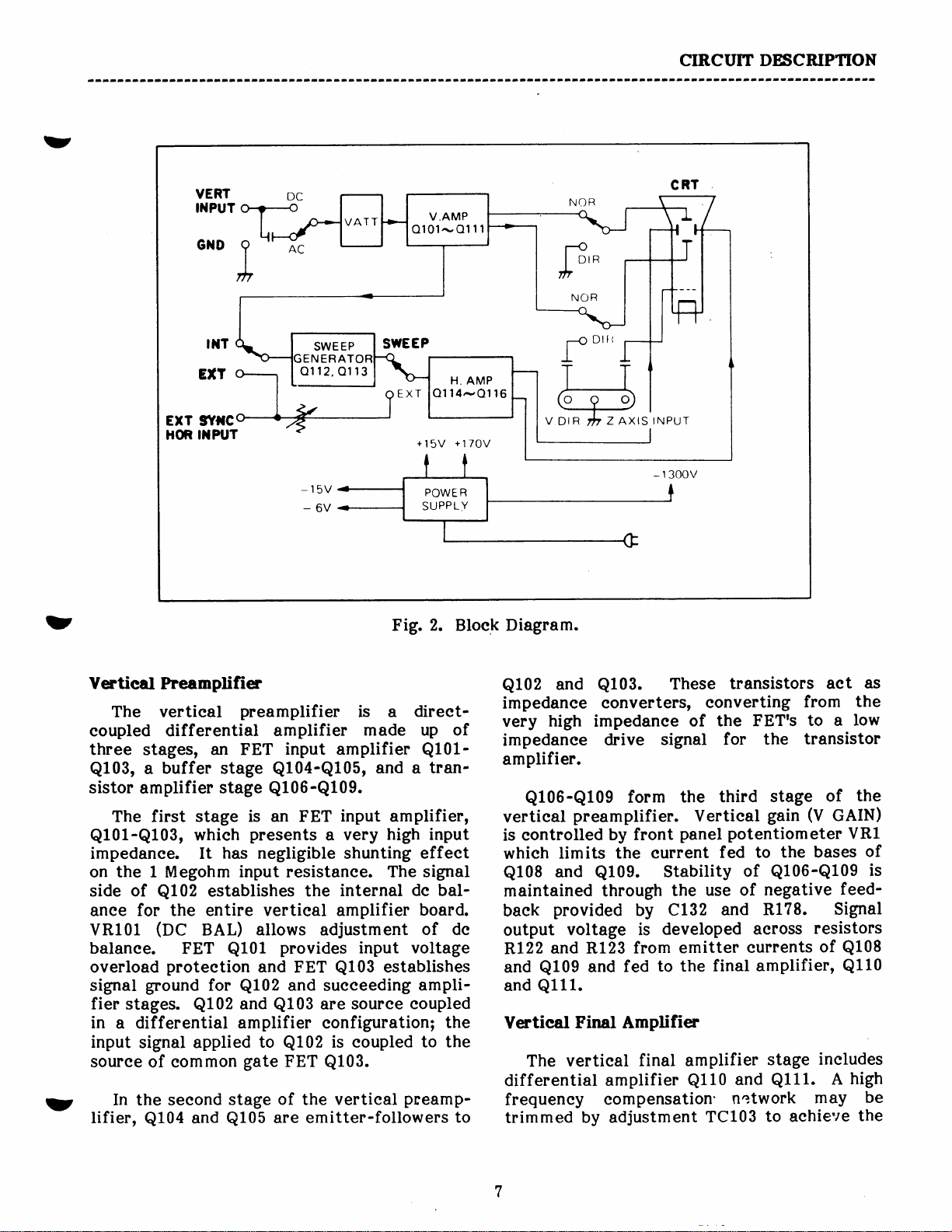
Vertieal
The vertieal
eoupled
three
Q103,
sistor
stages,
a
amplifier
The first stage
Q101-Q103,
impedanee. It
on the 1 Megohm
side of
for the entire vertieal amplifier
anee
VR101
balanee.
overload
signal
fier
in
input
ground
stages.
a differential amplifier eonfiguration;
signal applied
souree of eommon
In
rt
the seeond
lifier,
Q104
Preamplifier
differential
an FET
buffer
stage
stage
whieh
has negligible
Q102
(OC
establishes
BAL)
FET
Q101
proteetion
for
Q102
stage
and
Q105
2.
preamplifier
amplifier
input amplifier
Q104-Q105,
Fig.
is a
made up of
and a tran-
Bloek Diagram.
direet-
Q101-
Ql06-Ql09.
is an
presents
FET
a
input
very
amplifier,
high
shunting
input
effeet
input resistanee. The signal
internal de
the
bal-
board.
allows
and
Q102
and
Q103
adjustment
provides
FET
Q103
and
sueeeeding
are souree
input voltage
of de
establishes
ampli-
eoupled
the
to
gate
Q102
FET
of
is eoupled
Q103.
the vertieal
are emitter-followers
to the
preamp-
to
Q102
and
impedanee
very
high
impedanee
amplifier.
Q106-Q109
vertieal
eontrolled
is
whieh
Q10S
preamplifier.
limits the
and
maintained
baek
output
RL22
and
and
Ventieal
provided
voltage
and R123
Q109
Ql11.
Final Amplifien
vertieal
The
and
differential
frequeney
trimmed
by adjustment
Q103.
These
eonverters,
impedanee
form
signal
the
panel
drive
by front
eurrent
Q109.
through
Stability
the
C132
by
developed
is
from emitter
to the
fed
final amplifier
amplifier
transistors
eonverting
of the
Vertieal
FETrs
for
third
the
stage
gain
potentiometer
the bases
to
fed
of
Q106-Q109
negative
of
use
R178.
and
aeross
euments
final amplifier'
stage
and
Q110
Ql11..
eompensation'network
TC103
to aehieve
as
aet
from
to a
the
low
transistor
the
of
(V
GAIN)
VRl
of
is
feed-
Signal
resistors
of
Q108
Q110
ineludes
high
A
may
be
the
Page 12
CIRCIIIT
DESCRIPITON
MHz
5
tioning.
VRz,
and
the CRT are
and
NOR. At
volts
vertieal defleetion
eonneeted
ground.
output
eireuits for internal syne.
HOruZONTAL CHANNBL CIBCITrIII
the
sehematie
for full
Sweep Generator
reeurrent sweep sawtooth
around
lator operates
eonstant of
eireuit of
SWEEP
tanee eomponent of the
to the 10-100
ing
100-1 k
eapaeitanee
10 k
eapaeitanee of 390
10 k-100
the
SWEEP
series resistor
resistanee
RC time
fully
highest.
the
turned
bandwidth. Front
is
aeeomplished by
eOS,
I
Q111.
Q111,
With
A sample of
Refer
horizontal
The
The
a eapaeitanee
eireuit
sweep
when
this
per
division.
NOR-DIR switeh
direetly
is available to
to
diagram
eireuit
sweep
transistors
frequeney
Q113
RANGE switeh, 32,
position,
position,
position,
k
VARI/EXT GAIN eontrol, VR4,
eomponent
eonstant
eountereloekwise
The
eloekwise.
it shifts
as
The vertieal defleetion
fed from
NOR-DIR switeh
point,
to the V DIR terminal and
the
4 for
Fig.
ehannel
at
details.
generator
Q112
at whieh
determined
is
the eomponents
(Ca,
position,
of 0.47
C4
of 0.047
C5 is seleeted,
is
seleeted. In
R141, are seleeted as the
is
time eonstant is redueed and
RC
frequeney
panel
the de
the
the
waveform
55 set to
plates
vertieal final amplifier
the
a simplified
eireuits and to
the rear of
eireuit eonsists of a
and
C4, C5, VR4 and
RC eireuit:
C3 is seleeted,
UF;
is
seleeted,
pF;
when set to
pF;
and, when set to the
the stray
of
the
greatest
and its resistanee
is inereased
vertieal
potentiom
bias of
eolleetors of
of
the CRT
horizontal
oseillator
Q113.
the sawtooth
by the
in
seleets the
when set
eapaeitanee
eaeh
eireuit.
RC
when VR4
posi-
eter
Q110
plates
Q110
is
SS
set
is about
DIR, the
are
ehannel
diagram
the
manual
the
built
oseil-
time
RC
the
emitter
R141).
eapaei-
when
provid-
to the
providing
1 k-
the
providing
ease, the
and
The
V.R4 is
as
of
to
10
of
set
of
its
is
is
5 is a
Fig.
sweep
help illustrate operation
manner
applied.
portion
emitter),
voltage
With
eapaeitor
VR4 and
mined by the RC
deseribed. As the
voltage at the emitter
tively.
tively,
the threshold
threshold
Q113
sweep
lished by the voltage divider
VR4,
develops a
whieh
Ql12,
C108
for
the sawtooth
most
Q112
eolleetor,
of
eharge
is again
ramp begins. This eyele
peated.
a
approximately
limited
a
eapaeitor eharge eyele.
a
waveforms
Q112,
inverted
negative-going
inverted
of
oeeurs
sweep,
generator
First,
Q113
whieh deereases
The
eonduets and
range
and R141. This eonduetion
is fed
cutting
and R135 determine
Ql12.
point.
is inverted
Q113
period.
Now let us eonsider
syne
superimposed
Ql13.
just
partial
eireuit with
let us eonsider
of operation
During the
of
the sweep
Q112
at
R141. The
The voltage eontinues
negative-going
of eonduetion
to
eut off, and the
The sawtooth
to the
signal is
and applied
to
it will bias
eonduets
the base
off, the seleeted
eut
eharges toward
time eonstant
of
eonduetion
eapaeitor
negative
baek through
it
off.
This is the very short
waveform
The negative
to a
and is direetly eoupled
eontrol
At the end
+2
most linear
applied.
in Fig. 5. Syne
edge
positive-going
a
If this superimposed
before
sehematie
of the
where
negative-going
waveform
and establishes
of
Q113,
rate of eharge
eapaeitor
of
the bias
ramp
of
quickly
to
pulse
The RC
returns to
positive
sweep
the
waveform
volts to
eireuit
on the
to the
of the
the end
Q113
diagram
waveforms
eireuit.
the
no
eutting
-15
Q113
to ramp
is reaehed.
ends
Q113
diseharges
the de
of R138,
at
C108
time eonstant
the eutoff
pulse
this
of
negative-going
next
is
eontinuously
-2
portion
operation
Refer
signals
sweep
base of
syne
edge at
of a
into
eonduetion
of the
to
running
free
signal
syne
(at
sweep
volts through
is deter-
previously
as
eharges,
ramps
on
Q113,
when the
reaehed.
is
value
of
the eolleetor,
to the
interval when
positive-
its
the
at
pulse
to the base
eapaeitor
pulse,
ramps
volts, and
the sweep
of
again
are
reset
Q113.
input
signal
the
positive
free-running
is
ramp
Ql13
de
a
it off.
range
the
neganega-
until
the
estab-
Q113,
Q113
base of
of
period
base of
at the
dis-
Q113
re-
from
when
the
to
fed to
pulse,
base
edge
and
is
A
is
b
a
Yt
Page 13

CIRCUIT
DBSCRIPTION
v
POSITIONS
I
S
(sHowN)
r
t/to
t/
too
GNO
VERTICAL
FINAL
AMPLIFIER
Rr23
Rt
30
ml
tvDrRl I
-@-)
FET AMPL
o
Q
Q
vR
bc
lNoRl
:55
I
c6f
VERTICAL
lol
t02
ro3
rol
BAn
PREAMPLIFIER
BUFFER
CRT
6
TRANSISTOR
lvGArN
AMPL
I
ft
the sweep,
end
synehronization
observed.
Fig.
with three
used for internal
have
approaehing
However,
third
tive
edge
reaeh
sooner than
same
synehronizing
v
and for
forms.
HI FREO
COMP
Fig. 3. Vertieal
thus loeking the sweep
5 shows
eyeles
with
lrow
of
the waveform being
synehronization
square
syne. The
no
effeet, sinee
the sweep
the threshold of eonduetion.
the negative
edge
eyele of syne input
the base of
at
the threshold
in
the
prineiple
applies for
more
sine waves
The SIVEEP
Q113)
of
free
or less
or other types of . wave-
RANGE seleetion and
+I7OV
INT
TO
SWEEP
Channel
into
oeeurs
displayed and
wave
first
two eyeles
is not
yet
at the end of the
(inverted
eauses
to
a
Q113
posi-
eonduetion slightly
running
state. The
displaying
and
than three eyeles,
R3
SYNC
GEN
Cireuits, Simplified Diagram.
SWEEP
point
signal
Aetually,
of the sweep
state) must
between
pulses
VARI adjustment must
near
loeks
synehronization; then
the sweep
proper
for
generator
be a little longer
pulses
syne
when more
than
Syne Cireuit
to
The
vertieal
applied
other
may be seleeted by the
syne
signal may
ehannel or an
at the EXT SYNC
54. The seleeted
eoupled
level of
through
base
Q112
C107
syne
by
first be
into
synehronization.
syneronization,
(in
its free running
the
than the
(or
some
one eyele is
multiple of syne
viewed).
originate from
external
jaek.
syne
One
INT-EXT switeh,
signal
is
eapaeitively
and elamped to
diode D101.
to a
set
the syne
period
tirne
the
.signal
or the
de
the
Page 14
CIRCUIT DE.SCRIPIION
FET Buffen
buffer
FET
impedanee, low output
tween the sweep
final amplifier.
prevents
eonstant ramp rate.
Horizontal Amplifien
The
of a two transistor
Ql15
traee is
the front
supplied to
horizorrtal final
adjustment VR102, as
emitter eurrent available for
The
developed
the horizontal
to
"loading"
horizontal
and
Q116.
provided
voltage
Q114
panel)
base of
the
amplifier is
outputs
aeross R149
serves
impedanee
generator
In sweep operation,
of the RC
final amplifier
push-pull
Horizontal
by
VR3
as it
of
defleetion
and the horizontal
(
<>POS eontrol on
ehanges the dc bias
Q116.
it sets the limit of
Q115
and
plates
as a
positioning
preset
R150 and applied
high
input
stage
FET
Q
eharge time
is
eomposed
output stage,
of the
gain
The
Ql15
and
of the
by internal
and
Q116.
Q116
of the
CRT.
be114
are
final amplifier,
sweep operation, exeept
horizontal
the sweep sawtooth
LOW
Refer
the manual
of
The
whieh
operation, or
Taps also
tion. Neon
eonneeted aeross a
primtrV,
POWER switeh
A eenter-tapped
power
souree
signal
VOLTAGE POITBR SUPPLY
to
power
may
permit
eausing the
transform er
voltages
Ql15
is
the sehematic
for eireuit details.
transformer
be wired in
in
series
lamp
S106
of
and
being
signal.
parallel
for 230 VAC operation.
wiring
Nl and
100-volt segment of
lamp to
is
ON.
seeondary
provides
25 volts and
Ql16,
that the external
amplified
diagram
has two
for 100 VAC opera-
resistor R15?
just
instead of
at the
primaries
Ll?
for
light
winding
160 volts rms.
whenever
power
in
as
rear
VAC
are
the
the
of
supply
Y
EXTERNAL
When
eloekwise
generator
applied
provides
beam.
X-Y
operation,
duees X-axis
vertieal input
defleetion.
Refer to
diagram,
eireuit details. In this mode
switeh
generator
GAIN eontrol, VR4, is
FIOR INPUT
beeomes the
determines
m axim
At
zontal
division.
stant input impedanee
presents
lar
to
output
HORIZONTAL OPERATION
SWEEP RANGE
to the EXT
is disabled
at the
horizontal
This
or to the sehematie diagram for full
32 entirely
um
ehannel sensitivity
V.R4 is
negligible
Q102
of
EXT SYNC/HOR
mode
from
the level of signal
Ql14
of operation is
as
(horizontal)
produees
4 for
Fig.
Q114.
jaek
and FET buffer
Horizontal
(no
gain
eonneeted to
in the vertieal
is amplified
switeh
position,
and an external signal
defleetion of
the horizontal input
defleetion,
Y-axis
a simplified eireuit
diseonneets
The SWEEP
eonneeted
Gain eontrol,
applied to
attenuation), the
is about 300 mV
of 1 megohm.
shunting impedanee, simi-
by the
is set
52
the
INPUT
often ealled
of operation,
the sweep
VARI/EXT
between
Q114.
provide
ehannel..
fully
sweep
jaek
the CRT
pro-
and the
(vertical)
VR4
as it
Ql14.
hori
per
a
eon-
Q114
The
horizontal
the
Bridge reetifier D104
reetifieation, and
positive
1 17
C
regulates
+15
and Zener
side of the bridge to
the
reetifier
regulated to
These
plies",
tive,
horizontal ehannels.
A
voltage for the
amplifiers.
and
volt
whieh is
approximately
-
IIIGH
The
ation
voltage
and negative de voltages.
provide
the
volts.
diode
raw de from the
is
regulated
providing
high
+170
D103
peak)
volt
eonvert
filtered by
VOLTAGE
high
voltage for the CRT
is derived from
provides
is
eonneeted
filtering, and Zener
positive
C119 and
D106
dropped through
also
-6
volts
voltages
low
gain
stages
supply
vertieal and
Full wave
of the
+170
SUPPTY
voltage supply
side of the
C120
-15
by Zener diode
noise
160 volt
the
power
C114
volts.
provide
regulates the
volts. In
negative
are the
operation
in
the
provides
reetifier
transformer to de,
and
provides
500 volt winding
the
wave
full
provide
to
diode D105
side
rrelean
vertieal
the operating
horizontal final
diodes Dl02
output
rms
C115,
beam. The
both
C116 and
bridge to
filtering,
negative
addition,
of the
Rl55 and
D109.
of sensi-
providing
aeeeler-
sup-
and
(225
high
of
*
r
10
Page 15

CIRCTIIT
DESCRIPIION
v
SWEEP
GENERATOR
INT
FROM
A
SYNC
VERT
MPL
SYNC
CIRCUIT
at
c4
it-._*
c5
(--{
.,9
---lt----'
oilz
Qil3
v
o
POSITIONS
S2
(sHowN)
ro- roo
roo - rK
lK - roK
roK - roox
EXT
HMIZONTAL
FINAL
AMPLIFIER
IO2
VR
GAINI
I-noR
Fig.
4. Horizontal
Channel
Cireuits,
Simplified Diagram.
v
4",
___{€
co
I
-
*-1---lt------o
v
lcse
H+e
o\sz
\
SAWTOOTH
[l*€Etl
vanr
I
VR4
RUNNING_ NO
FREE
Qil5
EMITTER
Qil3
COLLECTOR
ll3
Q
EASE
WITH
YNC
S
sTGNAL
ll3
Q
I
EMITTER
oil3
COLLECTOR
Qil3
BASE
SYNC
J U
APPLIEO
m
SYNC
APPLIED
Fig.
5. Sweep Generator
power
the
v
eomposed
D108,
transformer.
of high
voltage diodes
and eapaeitors
voltage
A
C124, C12
doubler,
D107 and
5
and C126,
Cireuit Diagram and
eonverts the 500 volt
Filtering
vided by
lVaveforms.
for
the
high
eapaeitor
into
ae
voltage supply
C123.
The
-1400
-1400
volts de.
pro-
is
volts is
11
Page 16

SNCIIIT
DESCRIPIION
applied
sisting
R165,
fixed
age
0fuider
eontrol
the
eontrol
Beeause
erating
voltage
eontrol
voltage
CRT.
and
de
divider
eathode
aeross
of
high voltage
network
VR104.
grid
the anode
potential
divider
VR103.
to
a voltage
R159-R161,
R166.
be applied
The eontrol
network.
is
VR104
of the
voltage,
of
network
It seleets
divider
VR103'
available
Part
paralleled
adjusts
CRT
is
with
varying
thus
grounded,
1400 volts
also
a somewhat
the
to
network
R162'
grid
voltage
from
of the
by INTENSITY
the
respeet
total
I
is used.
ineludes
foeus
R163'
volt-
the
vol_tlg_!
voltage
to
brightness.
aeeel-
FOCUS
lower
grid
of
eon-
is a
at
the
The
the
final winding
A
provides
prevent a high
filament
the
volt
6.3
supply.
signal
A
terminal
eontrol
the
to
volts
late
amplitude
the
volts
6.3
and
winding
aPPtied
is eapaeitively
grid
beam.
CRT
the
of
the CRT
to
ae
potential
eathode
floated
is
at
the CRT.
of
more
or
power
differenee
the
of
the
to
Z
the
eoupled
A
intensity
will
transform
filament.
between
CRT'
voltage
high
AXIS
through
INPUT
signal
modu-
er
To
the
CLZL
25
of
b
3
L2
i,
Page 17
v
FUSE
ADJUSTTTIENTS
@trF-Cta
Printed
circuit
board
6
TC
lol
@
BAL
DC
101
VR
TC1
VR102
a
@
HOR
. GAIN
6
TC1
01
02
@
o
v
ADJUSTfrTENT
1.
2.
'-
3.
WARNIilG
The CRT
on the
rnltoges of
cnd
wltage sofety
inside
the
Allow
time
making this adjustment.
the operating
Set
SWEEP
EXT.
V ATT
I
i
vertieally on CRT.
With no
present
socket and cerAain
circuft
board
apprcximately
+170
lplts. Obsente
prccoutions
coven
front
OF DC
at least
for the
BALANCE
15 minutes
unit
RANGE
switeh to GND.
POSITION
signal
on
the CRT.
eontrol
applied,
to stabilize
eontrols
to any
6.
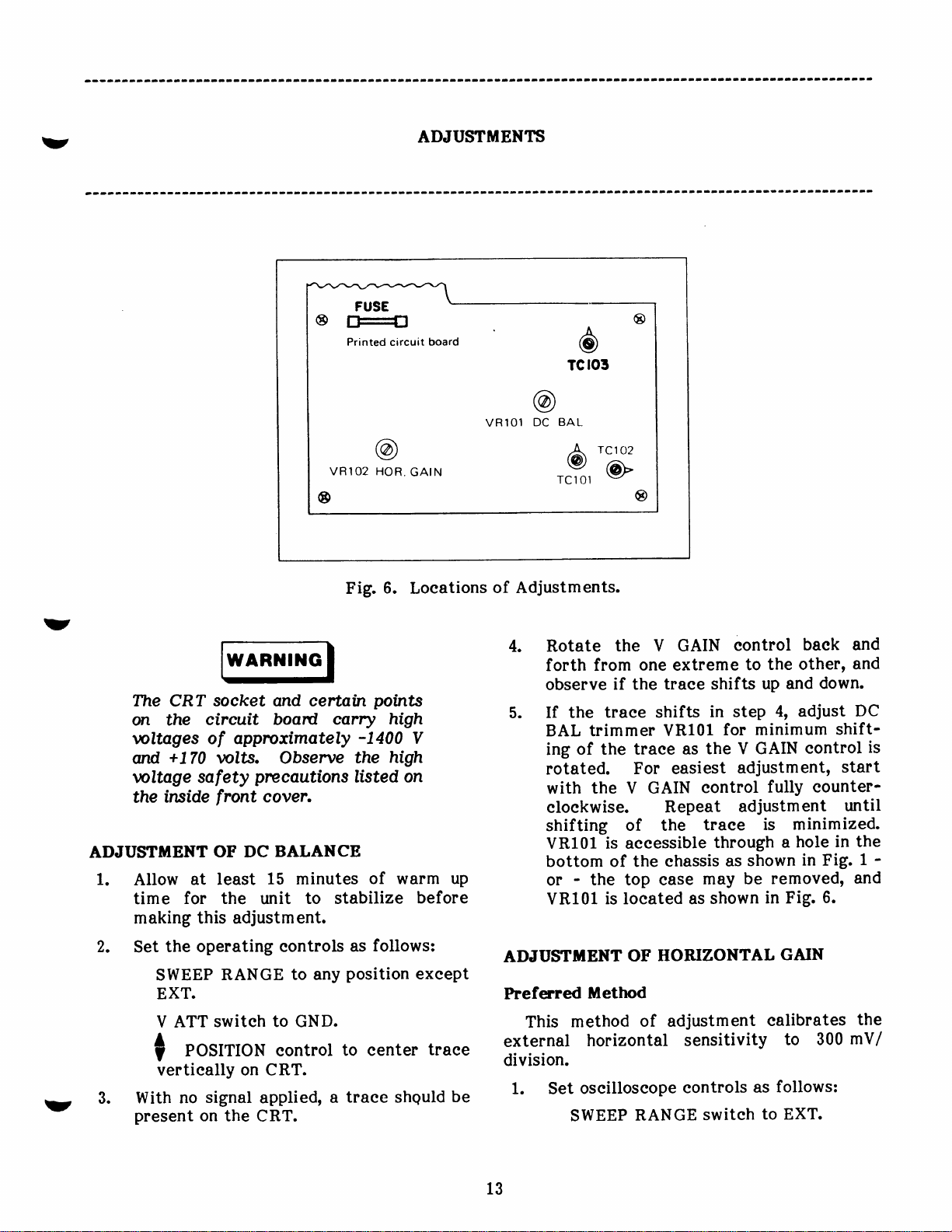
Fig.
Loeations
polnts
carry high
-1400
high
the
listed
on
of warm
follows:
as
position
to eenter
traee shquld
a
V
up
before
exeept
traee
be
of Adjustments.
Rotate the
4.
forth from
observe
If the
if the traee
traee shifts
BAL trimmer
of the traee
ing
rotated.
the V GAIN
with
eloekwise.
shifting
VRl01 is aeeessible
bottom of the
-
the top ease
or
VRl01
is loeated as
ADJUSTDIENT
Preferred
This
external
illetlpd
method
horizontal sensitivity
division.
1. Set
oseilloseope
SWEEP
V GAIN
one extreme
shifts
in step
VR101
for
as the
For easiest
eontrol
Repeat
of the
traee
through
ehassis
as
may
shown
HORIZONTAL
OF
of adjustment
eontrols
RANGE
switeh
eontrol
to
baek and
the other,
up and
down.
4, adjust
minimum
V GAIN
eontrol
adjustment'
eounter-
fully
adjustm
shown
ent
minimized.
is
hole
a
in Fig.
be removed,
in Fig.
6.
GAIN
ealibrates
to 300
follows:
as
to EXT.
and
DC
shift-
is
start
until
in the
1
and
the
mV/
-
13
Page 18

ADJUStrMENTlI
Length
horizontal
lection
def
b
of
Larger
H.
GAIN
Smaller
H.
GAIN
SWEEP
VARI/EXT
eloekwise.
V
ATT switeh
POS to eenter
?
2. Apply a ealibrated
square wave at
to the EXT
Conneet
the signal eom
1
SYNC/HOR
jaek.
3. Adjust
horizontal
HOR GAIN
defleetion
VR102 is aeeessible
bottom
of the ehassis
ease is removed,
shown
Alternate
This
length for
but
brated"
ilethod
method
10 divisions horizontal
external
The effeets
are shown in
1.
oseilloseope eontrols
Set
in
Fig. 7.
6.
Fig.
of adjustment
horizontal operation
of HOR GAIN
SWEEP RANGE
exeept EXT.
SWEEP
VARI/EXT GAIN
eloekwise.
V ATT switeh
POS
i
to eenter
7. Effeets
Fig.
GAIN eontrol
to
GND.
traee vertieally.
the
p-p
V
3
(with
kKz
trimmer
of
through a
(see
VR102
switeh
to GND.
traee
the
of HOR GAIN
fully
sine wave
no de offset)
INPUT
mon
VR102
10
jaek.
to the
J
for a
divisions.
hole in the
1). If the
Fig.
is loeated
sets the sweep
defleetion,
is uneali-
adjustment
follows:
as
to any
position
eontrol
fullY
vertieally.
or
as
Adjustment
2. A traee
3.
Adjust+POS
the traee
of the
edge of the CRT
4.
Adjust
traee length of
aeeessible
of the
removed, VR102
VR104.
should
be displayed
eontrol
is visible, and aligned
gratieule
markers
sereen.
HOR GAIN
trimmer
10
(see
a
Fig.
through
ehassis
is loeated
Fig. 6.
TRACE
netie
the
ROTAIION ADJUSTUENT
earthts
The
fields
oseilloseope
magnetie
may
eause
is
moved
field and
the
another. This adjustment
eomeet
1.
Set
for traee
the operating
SWEEP
tilt.
eontrols
RANGE
to anY
EXT.
applied,
CRT.
The
to GND.
the
traee
V
ATT
With no signal
2.
present
eontrol to
the CRT.
with the
traee tilt
switeh
on the
eenter
horizontal
is noted,
adjustm ent.
3.
Refer
to
Fig.
8.
Loosen
on the CRT.
beginning of
the
so
with one
near
the left
VR104 for a
divisions.
VR102
hole in the bottom
1). If
the ease
as shown
magwhen
CRT
exeePt
the
traee
one
from
rotates
as
Position
traee should
a
Adjust
other
to tilt
loeation
the
follows:
traee vertieally
parallel
should
gratieule
make the
be
following
two serews
the
line.
is
a
is
in
to
to
be
POS
on
If
b
L4
Page 19

ADJUSTMENTS
v
It
It
Fig. 8.
(A)
holding
the rear.
4. Plaee a wide blade serewdriver
(g)
the traee
gratieule
5. Carefully tighten serews
that the
serews
FREQUBN CY COMPENSATION
ADJUSTMENTS
1. Remove
2.
Set
3.
Appty
INPUT
to the
generator
turn the
to
oseilloseope eontrols as
V ATT switeh to
V GAIN
SYNC switeh
SWEEP RANGE switeh to
a
the
CRT
CRT
parallel
is
line.
traee does
are tightened.
the
eontrol
kHz
1
jaek.
jaek.
into its
from the unit.
ease
1
fully eloekwise.
to
INT.
square
Conneet the
Terminate
mounting
mounting
with the
not rotate
(10
wave to the
eharaeteristie
plate,
(A),
follows:
mV/DIV).
100-1
signal eommon
the
square
Tlaee
plate
into
horizontal
observing
when the
Rotation
at
slit
until
k.
VERT
wave
impe-
o@
Adjustment.
4.
5.
6.
1.
@a
danee
with an output
nate
Adjust
wave
tude of
Adjust
eontrol to
the square wave.
Adjust
position
CRT.
Adjust
most ideal square wave
shown in
If
adjustment
tion trim m
follows. Conneet
having a flat
least
the sweep
1 kHz to 5 MHz and
ize the oseilloseope
output
(i.e.,
into
50 n).
the output
generator
6 divisions on
the SWEEP
display two
tne $ POS and
thd display
trimmer
Fig.
desired,
il additional
5 MHz
of
the
for a square
9.
high frequeney
of
TC103
er
response
to
generator to
sweep
wave
impedanee
level
for a waveform
eapaeitor
vertieal
the
generator.
of 50
of the
the CRT sereen.
VARI/EXT
four eyeles
to
+
POS
in the eenter
TC103
waveshape,
eheek for
may be
a sweep
from
input.
sweeP
externally
sweep
to
generator
ff termi-
square
ampli-
GAIN
eontrols
the
of
for the
proper
eompensa-
rnade as
generator
kHz to at
1
Adjust
from
synehron-
trigger
the
fre-
The
of
to
as
15
Page 20
ADJUSTMENTS
I
__t__
h
I
I
a
\-
queney
on
output
the
referenee.
frequeney
peaks,
at
Next,
8.
inerease
response
the
CRT.
level
CRT at
and
least
4.2 divisions
set the V
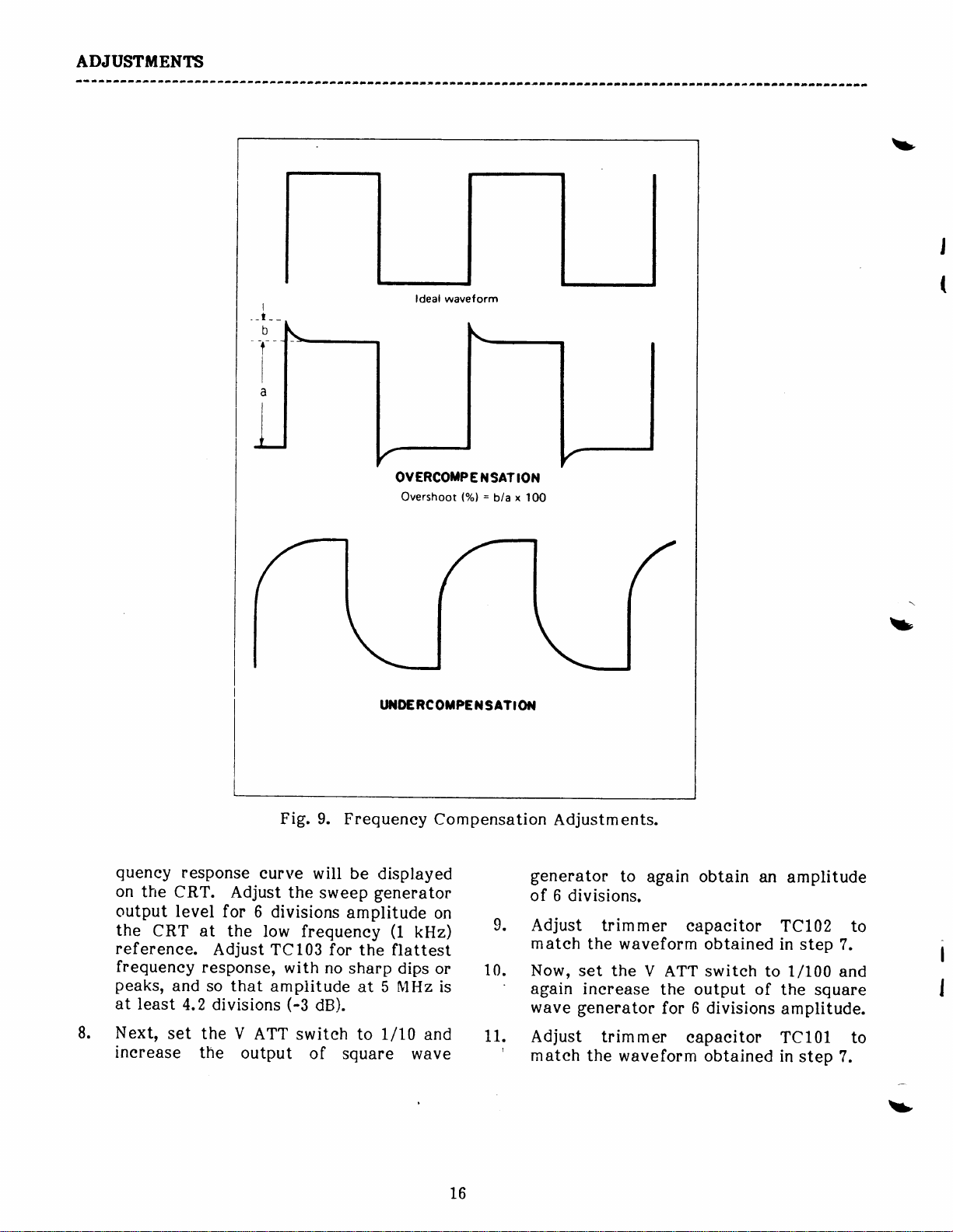
Fig. 9.
eurve
Adjust
for 6
Adjust
divisions
the
low frequeney
TCt03 for
response,
so that
amplitude
ATT switeh
the
output
Frequeney
will be
the
sweep
amplitude
with
no
sharp
(-3
dB).
of square
OY ERCOI{P
Overshoot
T'I{D€ RCOilPE
Compensation
displayed
generator
on
(t
kHz)
the flattest
dips
or
NlHz
at 5
L/10
to
and
wave
is
E N
l"/ol
il
ION
SAT
=
bla x 100
SATI Oil
9.
10.
'
11.
'
Adjustments.
generator
of 6
divisions.
Adjust
mateh
Now,
again
wave
to again obtain
trim mer
the waveform
set the
inerease
generator
Adjust trim
mateh
the
waveform obtained
eapaeitor
obtained
V
ATT
switeh
the output
for 6 divisions
mer
eapaeitor
an
amplitude
TCl02
in step
to 1/100
of
the square
amplitude.
TCl01
in
step ?.
to
7.
and
to
=
I
16
t>
Page 21

I}IAINTENANCE
I
t
Remove
these
screws
@
6
I
v
CASE REIIOVAL
these
Loosen
WARNIilG
screws several
turns
Fig.
I
I
I
I
10.
Case Removal.
3.
s
s
Grasp the
rear,
to
then lift
earrying
ease off.
handle
and
slide
High
voltage
present
rs
rcmoved
is operuting.
present
is
input
power
tive outlet,
POWER swrtch
sen e
prccautions
srde
I
ll
1.
Refer
from
2.
Loosen
the eenter
v
several
front
unl.
to
eaeh
the
turns.
when
and the
on
circufts
plug
rs
high
the
listed
cover
10.
Fig.
side
of
remaining
front
-l$A
to
W
the ccse
oscilloseope
AC line wltage
certain
any
connected
even if
fs
OFF. Ob-
wltage saf
on the in-
of
Remove
the ease
seetion
volts
Wvger
time the
thrs m@7-
as
serew
of
is
to a
the
ety
two
serews
shown.
loeated
eaeh side
at
FUSE REPLACEMENT
wARlililc
AIwoys
ac
fuse.
ent
ever the
nected
even
switch
1. Rernove
2. Remove the
(loeated
refer
the
operatior,
4[.9g6.prrri'rr'1.
outlet
on
to
proper
before
AC
line voltage rs
the
Wvoer
to o
tf
the scopets POW
rs
OFF.
the ease
fuse from the
on
the
Fig. 6)
value;0.5
0.3 A for 230 volt
fuseholder
and insert
:
r-(]i;:''
replacing
cord is
lrve ac
from the unit.
printed
fram
pres-
when-
con-
outlet,
ER
fuse
eireuit board,
a new fuse of
for
A
operation.
ct
holder
Il7 volt
t7
Page 22

TIAINTENANCE
3.
Troubleshoot
eause
malfunetioning
of
the blown
the
oseilloseope for
fuse and repair
eireuit.
the
the
1.
Remove the ease
2.
Remove the soeket from the CRT.
from the unit,
IINE YOLTAGE
7.
Aluays
ac antlet
age
conversion
age may be
tronsformer
power
live
ac
POWER switctr fs
After
fuse
for
Model
The
are faetory
line voltage.
volt
or 230 volt
the
power
ing
conversiorq replace
witlt
the new
A f or 100 V or
0.5
0.3 A
wired for Ll?
transformer
CONVERSION
WARNING
disconnect scope
bef ore startfng wlt-
AC line
present
whenever
cord ts
for
1403A
They m
50/60 Hz operation by
ionne cted to a
outlet,
the
230 V.
even
cotrect value
line wltage:
and
ay
OFF.
1405
be
as
from
volt-
on the
the
if the
the
777 Y.
Oseilloseopes
volt,
50/60 Hz ae
rewired for 1
shown in Fig.
00
rewir-
11.
Completely
3.
whieh attaeh
the rear
Remove
ehassis, ineluding the
CRT shield
5. Loosen the two elamping
the
CRT
from
the
6.
To replaee the CRT,
ure. Adjust
CRT
seetion.
FRONT PANBL
is installed; see ADJUSTMENTS
Handle the
Rough handlirry may berd or
cruck the
remove the two serews
the CRT
of the ehassis
the entire
(Fig.
12).
(Fig.
band
shield.
traee rotation when
RETIOVAL
pnel
putel.
mounting
(Fig.
CRT assembly from
mounting
12)
and
reverse the
carcfully.
plate
8).
plate
serews
slide
the CRT
to
and
from
proeed-
new
the
CRT
7.
REUOVAL
Alwcys
fully.
wrcuum.
may
glass,
Resulting
ments could
When replacing
careful
the socket wrth
tioned in
tfon
ace).
f
AND BEPLACEiTENT
lwndle
Tfl.e
cruck or
causfng
to
(when
WARilING
CRTts
CRT is under
Cclsless handling
weakqt
ttimplosfontt.
an
flytng
cculp injurry'.
place
the
viewed
glcss
the
the tube in
the key
Wper
tube,
left direc-
from
crrne-
high
the
rag-
f
be
posi-
the
Remove the ease.
1.
Loosen set serews and
2.
Unserew the
3.
SWEEP RANGE seleetor
Remove the
the
EXT SYNC/HOR
terminal.
J
5. Remove
seetion
seope).
6. Carefully
blaek serew from between
two
of the
pull
the
remove
mounting
INPUT
serews
front
from the lower
panel
panel
knobs.
all
nut from the
switeh shaft.
terminal and
(bottom
forward.
of
t/
18
Page 23

TIAINTENANEE
I 17
100
0
il7
t00
o
oc2re
Fig. 11.
6.3v
0.6A
!0ov
Power
cord
il7
r00
0
@
il7
r00
0
llTv
To
terminal
@
Line
Voltage Conversion.
Power
Power
cord
il7
r00
0
il7
t00
0
SW
Y
for
Clamping
Fig.
screws
C.R.T.
12.
CRT Removal and
Replaeement.
ry
19
Page 24

TROT'BI,ESHOOTING
v
The following
oseilloseope.
to
the
eorresponding
VOLTAGE
After repairs
repair has
CHART
fully
OPBBAIIONAL
1.
Conneet
Turn on POWER
light should be lit.
Set V ATT
RANGE switeh
snd<>pOSITION
and
INTENSITY
dot
should appear in
eenter
portion
Do
not
remain
thon
may
burned.
go
or
nOperational
They should be
nTroubleshooting"
seetion
are eompleted,
restored
performed
of
proper
CHECK
power
switeh to
to
eontrol to maximum.
of the
allow
stctroncry f or more
a
seconds.
few
become
Reduce
into
sweep mode.
to
eord
switeh.
GND and SWEEP
EXT. Set I POSITION
eontrols to mid-position
the approxim ate
sereen.
a bri.ght dot
fi7e
permanently
INfENSIfy
Cheeks" will eompletely eheek
in
the listed sequenee.
information
manual
this
"Operational
the
operation,
live
ae outlet.
neon
The
to
CRT
for normal voltages at all transistors
Cheeksft
and to
pilot
A
isolate
to
should be repeated to
make sure
pilot
No
failure
power
lamp Nl, R15?.
If unit
former seeondary windings
eheek
eheek
c115,
No
supply
pins.
winding
cl21-Cl26, R158-Rl67,
high
If
voltage. Cheek CRT
(power
that
light usually indieates a
in
the
transformer, POWER switeh
blows
for shorted
power
C116, C117, C118,
dot usually
or
CRT
high
If
of
voltage
removed).
funetional
If
the defeetive eireuit.
no
TB,OT'BI,ESHOOIING
power
fuses,
supply
power
seope
the
additional
input
diseonneet
power
filter eapaeitors C114,
indieates a
failure.
voltage
transform er,
normal, eheek CRT
filament with ohmmeter
operation of
fails
any
verify tha'
problem
eireuit.
one at a time
supply.
C119, C120.
high voltage
Cheek
abnormal,
VRl03, VR104.
voltages at CRT
step,
Refer
and the
blown
power
eheek 500 V
D107, D108,
t,
{
exists
fuse
Cheek fuse,
S106,
neon
trans-
Espeeially
power
filam
or
and
!t
ent
Rotate
extrem
beyond
Adjust dot to vertieal
es.
POSITION
t
Dot
top
the
should be adjustable
and bottom of sereen.
eontrol
eenter of
both
to
sereen.
Non-eentered
indieates vertieal ehannel
voltages
at
or laek of
Q101-Q111.
20
adjustment range
problem.
M
easure
v
Page 25

TROITBLESHOOT'ING
OPEBATIONAL
4. Rotate
extremes.
beyond. the
sereen.
of sereen,
Set SWEEP
5.
position.
the CRT.
6.
sharp,
A
by adjusting
eontrols.
<>POSITION
should
Dot
left and
to
Adjust
A traee
elear
dot
RANGE
should
traee
FOCUS
the
switeh
should
CHECK
both
eontrol
be adjustable
right edges
horizontal eenter
be displayed
and
to
of the
k-100
10
to
be
obtainable
INTENSITY
on
Non-eentered
indieates
voltages
ure
k
No
power
final
With
form
eheek
If sawtooth
waveform
voltages
Improper
INTENSITY
or
R158-R166,
horizontal
traee
amplifier.
another
indieates
supply,
emitter
at
voltages
at
at
Q114,
operation
TROUBTESHOOIING
adjustment
laek
or
at
Q114,
sweep
seope,
of
at
Q112,
present
Q115,
Q115'
eireuil
elzl,
of
ehannel
Q115'
failure
generator, or
eheek
Q113.
at
Q116
indieates
e122.
Q116.
for
Q113.
Q113'
eolleetors.
Q116.
Cheek
problem. Meas-
of low
sawtooth
If
eheek
failure
VR103'
range
voltage
horizontal
wave-
no sawtooth'
sawtooth
Measure
FOCUS
in
VR104'
!7.
8.
Rotate
treme to
shift
Apply
at
ATT
eontrol
and
be
defleetion.
be unsynehronized.
Set
9.
position.
adjust
Synehronized
be
tion
ized
V GAIN
the
more than
mV
40
Hz
100
switeh
to
AC-DC
approximately
SWEEP
SWEEP
obtainable.
1
to
display
eontrol
other.
p-p
to VERT
to
maximum
switeh
The
RANGE
Set
display
division amplitude.
should
The
1 division.
sine
rrlrt
(10
to AC.
4 divisions
waveform
SYNC
VARI/EXT
Reduee
still
from
traee
wave
INPUT
switeh
switeh
of waveform
(14
jaek.
mV/DIV)'
(futly
There
display
GAIN eontrol
vertieal
be obtainable.
ex-
one
should
eloekwise),
of
to
to
Synehron-
not
mV rms)
V
Set
GAIN
V
should
vertieal
may
10-100
and
INT
should
deflee-
Shift
adjustm
No
voltage
With
wave
at
If
sawtooth
another
able
VARI/EXT
VR104,
If
of
ent
vertieal
power
another
signal at
Q101-Ql11.
display
seope.
from
and
sawtooth
R132,
54,
traee
eannot
C10?,
indieates
VRl01.
defleetion
supply
seope,
Ql02-Q111.
wavef
about
orm
Make
GAIN
Ql12,
frequeney
D101.
need
indieates
or
eheek
be synehronized,
at
Q
sure
100
to
Hz
10
eontrol
Q113
eireuit.
is okay,
for DC
failure
vertieal
presenee
Measure
1 13 em
sawtooth
Hz
not,
If
eheek
BAL
in low
ehannel
sine
of
voltages
eheek
first
itter
with SWEEP
eheek
with
is adjust-
C3'
R131'
21
Page 26

TROI'BLESHOOTING
10. Apply
1 kHz
switeh
about 4 division
Synehronized
11.
obtainable
Apply
L2.
10 kHz to VERT
switeh
about
13.
Synehronized
obtainable
!4.
Leave sine
INPUT
SYNC/HOR
switeh
p-p.
should
OPERAIIONAL
p-p
V
0.4
VERT INPUT
to
to 1/10. Again
4 V
to
4 division of vertieal
jack
to EXT.
Synehronized
be obtainablq
sine wave
of vertieal
waveform
on 100-1 k SWEEP
p-p
sine wave
1/100. Again there
waveform
k-10
on 1
wave applied
and
INPUT
CHECK
jaek.
INPUT. Set
k
SWEEP
apply
also
jaek.
Reduee
waveform
(0.14
V rms)
V
Set
there
defleetion.
display should
RANGE.
(1.4
defleetion.
display should
RANGE.
to the
it to
Set
signal
ATT
should
V rms) at
ATT
V
should
VERT
the
EXT
SYNC
2 V
to
display
at
be
be
be
be
TROI'BI,BSHOOIING
no or
If
I/n
Cheek
no or ineorreet
If
ineomeet
attenuator
52.
C4,
51,
1/100 attenuator
TC101.
Cheek
Cheek
C5, S2.
R1, C2,
s4.
vertieal
R102,
vertieal
sl,
R106,
R101,
defleetion
C102'
defleetion
TC102.
Rl05,
eheek
v
eheek
Cl01,
:
15.
Set AC-DC
square wave
offset to
display should
about
divisions), Set
Waveform should
Apply 3 V
16.
60 Hz to EXT
Return
position.
eontrol
There should
of
sions
Ll.
Apply
GND terminals. Set
DIR.
amplitude
to
switeh
or sine
VERT INPUT
+2
divisions
p-p
sine wave
SYNC/HOR
SWEEP
Set SWEEP
maximum
to
be approximately
horizontal defleetion.
p-p
10 V
A waveform
signal
should
DC.
wave
jaek.
vertieally
be
(extend
AC-DC
be eentered
RANGE switeh
VARI/EXT GAIN
(fully
between
NOR-DIR
of about
be displayed.
Apply
with
Waveform
from 0
switeh
about
(1.05
V
INPUT
eloekwise).
V DIR
1 division
V
4
P-P
+2
V de
eentered
+4
to
to AC.
0.
at
rms)
jaek.
to EXT
10
divi-
and
switeh
to
Cheek
Ineorreet
indieates
vR102.
Cheek
S3, Cl.
55, C6,
amount
need
for
C7,
of
HOR
R2,
horizontal
GAIN
R3.
defleetion
adjustment
v
22
Page 27

TROTIBLESHOOTING
U
OPERATIONAL
18.
Return NOR-DIR switeh to NOR. Apply
60 Hz
Z-AXIS INPUT terminal and VERT
INPUT
display of
waveform
signal of
jaek.
a f ew eyeles. Displayed
should
at least 25 V
Adjust
CHECK
for
synehronized
be intensity
TROUBLESHOOITNG NOTES
p-p
to both
modulated.
TROUBLESHOOIING
Cheek R164,
elzl.
23
Page 28

PARTS IJST
IiIPORTANT
:
parts
This
end of
ordering
PRODUCTION CHANGES
diff erenees.
There
unless
aeeompanies
express
or
replaeement
list refleets
produetion,
parts
a minimum eharge
is
previous
for later version
U.$A.
open aecount
order.
eharges. Speeify
parts.
the
the
and
PARTS ORDERING
Advanee
ORDER
K-Preeision,
B &
Faetory Serviee
6460 West Cortland
REPLACET}IENT
Telephone:
Model
seetion at
for
Chieago,
1403A from
Model
1405
Model 1405,
eaeh
arrangements
remittanee
model and
Dynasean
Illinois
(312)
Telex:
start
the
the start
at
first eheek
this
the end
invoiee. Orders
Operations
25-3475
of
INFORIUAIION
have been
must eover
serial
PARTS
Corporation
Street
60635
889-8870
number
FROM:
produetion
of
produetion. When
of
HISTORY
the
manual
be shipped
will
made or
handling
for
remittanee
and
when
ordering
to the
OF
possible
C.O.D.
postage
;
24
U
Page 29

PARTS
ITST
v
SCHEUATIC
SYMBOL
DESCRIPTION
DYNASCAN
PART NO-
RESIfYTOBS
04-5-104
002-1
002-102-5-225
002-102-3-994
002-102-3-904
. .
002-102-5-105
002-102-3-105
002-001
.
002-001
-1
04-5-1 02
002
002-104-5-562
. . .
002-104-5-822
. . .
002-104-5-101
. .
04-5-682
002-1
.
002-104-5-101
002-1 04-5-222
.
002-104-5-332
. .
002-104-5-222
.
002-104-5-4?0
o.
002-1 04-5-472
002-104-5-391
002-104-5-221
. .
002-104-5-681
o.
002-104-5-330
. .
-003-5-392
1
01
.
002-104-5-L24
.
002-104-5-273
002-104-5
.
002-104-5-124
.
002-104-5-272
.
002-104
002-1 04-5-682
..
002-104-5-332
04-5-1 83
002-1
002-104-5-683
04-5-1
002-1
002-104-s-103
. . .
04-5-123
002-1
002-104-5-392
002-104-5-331
. .
011-002
002-104-5-333
.
002-104
-1
011
09-9-001
011-002-5-681
011-003
. .
002-102-5-t22
002-104-5-1
002-102-5-473
.
002-1 02-5-1
.
002-102-5-27
-9-024
-9-02
1
-472
-5-152
23
-5-223
-5-124
-5-47t
04
05
4
5
R1
3
R2,
R101
R10 2
R103
R104
R105
Rl06
R107,
108
R10I
R110, 111
Rl12
Rl13, 114
R115,
116
R11?
R118,
119
R120
Rl21
RL22,
1213
Rl2 4
Rl25, 126
RL27
R128
R129,
130
Rl31
R132,
133
R 134
R135
R136
7
R13
R138
Rl39
R140
Rl41
F"L42
Rl43
R144,
R146,
145
14?
Rl48
R149, 150
R151
Rl52
R153
4
R15
R155
6
Rl5
R157
R158
R159-161
R162
100 k0t5%,
2.2
Mfltl%, L/2 WrCarbon . . . . r r o o o
kO
990
900
kO
1
MO
tl%rL/zWrCarbon
1 MQ
tLyorL/2WrCarbon
I/4W,
Llz W,
t196,
tl%rl/zWrCarbon
10.1 kOtl%, l/2
111 k0
1 k0
5.6 kfltS%,
8.2 kfl
100
tlyorl/2
t596rL/4WrCarbon.
L/[WrCarbon .,
tlyorL/4W,
O
tl%rL/4WrCarbon .
Carbon
Carbon .,
W,
Carbon.
WrCarbon
Carbon,
6.8 kfltS%, l/4WrCarbon . . . . .
100
Ots%, t/4W,
2.2kntlyo,
kOtS%,
3.3
2.2kfl,tS%,
47
Atl%rL/4W,
4.7 k0
I/4 W,
L/4WrCarbon . r
L/4W,
L/4W,
t596,
Carbon.
Carbon . . o . .
Carbon .
Carbon...
Carbon
390 nt5%, L/4W, Carbon.......
,............
. . r . . . . . . . .
. . . . . . . . .
. .
. . . . . o. ...
....
. . . . . . .
..
. . .
. . . o
. . . r i
o
. . . . .
. . . . r . . .
. . . . . . o . .
. . .. . . . .
. . . . . . . .
. o . . . o . .,
. . . . . . . . o
. .
. . . . . . .
o............
. . . . . . .
. . . . . . . r,
. . . . . . r . . . .
r.........
. . . . o . .,
., . . .
o......
. . . .
220nts%, L/4W, Carbon . . . . . . r . . o, .
680
n tlyorL/4W,
33 n tl%rL/4
3.9 kfl
3
t596r
120 kfrtS%, L/4WrCarbon . . ., o . . r
27 k0t596rI/4WrCarbon
4.7 kQtS%,
120 kn
2.7 kfiltS%,
1.5
kfltS%, L/4WrCarbon
kfltS%, L/4WrCarbon
6.8
kO
3.3
kOtS%, L/4W,
18
68 kntS%,
12 kO
10 kO
12 kn
3.9
330
22 kntS%, 2 W,
33 kOtS%,
120 kO
820 Ot5%,
680
470 fltS%, 3
1.2 kfl
100 k0
47
1 MO
2?0
t596,
t596rL/4W,
tiyo,
k0
fltS%,
A
t'%r2WrMetalFilm.
kO
t5%,
Lli;yo,
kCItS%, L/2
I/4W,
t/4WrCarbon . . .
tlyo,
L/4W,
tl%rL/4WrCarbon
L/4WrCarbon
l/4W,
I/4W,
tl%rL/4WrCarbon
L/4WrCarbon
L/4W,
l/4WrCarbon
ti7o,
3
*,596,
l/2 W,
t596rl/4W, Carbon
t/z.W,
l/2 W,
Carbon............
W,
Carbon. . . r .
W, Metal Film ....
. . . .,, . r
.......
. . . .
. . . . . . . . . . .
. .
.
Carbon . .
. . . . . . . . . .
. . . . . . . . .
Carbon . .
Carbon .
Carbon .
Carbon o
Carbon .
Metal Filnl. . . r
Carbon . . .
W, MetalFilm. r . . .. . . . . ...
W,
Metal
WrCarbon ..
Film.
Carbon
Carbon .
Carbon . .
. . . . o . . . . o
. . .
. .
..
. . . . . r . . .
. .
. . . . . . .
..
o . . .,
..
. . . .
. .
. . . .
o.
. o
..
. .
.......
. . .
. . . . . . ..
o .. . . . .
o . . . . . . . .
. . . . . . . .
., . . . . . . .
. . o . . . . . r o .
. . o o ., . ., .
. . . . . . . . .
. . . . . . . . . .
. o . o . o o . . .
.
. . . . . . . . . .
. .
. . . . . . . . . .
.,
. .
. .
. o . . r . . . .
. . . . . . .
. . . . . o
. . . .
..
. . o .
. . o o .
. . . . .
r.....
. . . .
. . . . .
25
Page 30

PABIE
IIS'T
SCHBIATIC
SYiIBOL
R163
Rl64
R165
Rl66
R16?
R168,
169
Rl78
vRl
vR2
vR3
vR4
vR101
VR1O2
vR103, 104
c1
c2
c3
c4
c5
7
c6,
c101
c102
103
c
c104
105
c
c106
107
c
cl08
109
c
cl10
c111
cLt2
c113
c114,
c116
cl17
c118
cl19
c120
CIzL
CL22
cl23
cL24,
c126
CL27
c128
115
L25
DESCRIPIION
kntS%,
560
2.2
MntS%,
Llz W,
I/2WrCarbon
150 kntS%, L/2WrCarbon
180 k0t5%,
I/ZW,
100 kntS%, LlzWrCarbon
100
0t5%, Il4WrCarbon
180 kOtS%,
2 kO
Potentiometer
I/4WrCarbon
500 n Potentiometer
10
kQ Potentiometer
1 MO Potentiometer
Control). r . . ' . . . . . . . o . r . r
4.? kflTrimmer
1 kn
Trimmer Pot
1
Mn
Trimmer Pot
INTENSITY Adj)... o. r...
1
0.
15
0.47
0.047tIF
3900!F
0.47UFr 630 Vr Oil
680
68
0.01
0.01
180
15
1
11tr, 63 V,
15
390
10tlF,25V,
680
330
4?
220
220
220
220VFr
t00
0.01
0.22
0.1
0.1
0.1
100
0.01
630 Vr
llF,
pF
t5%,
t10%,
LiF
t10%,
pF
t5%,
pF
t5%,
t20%,
uF
t20%,
UF
pF
t5%,
pF
t5%,
50 V, Non-Polarized Eleetrolytie
tF,
Oil r. D... r..
500 V,
tfOX,
Polystyrene.
Polystyrene. . . . . r
Ceramie Dise .
Ceramie
Eleetrolytie . t r
pF
pF
Ceramie Dise . . . . . .
t5%,
t5%, Polystyrene. .,
Eleetrolytie . r........
pF
t2096,
pF
250 V,
tF,
UF,
1fi,50
pf
,
ljF,25V,
trF
ttF
t10%,
lIF
tIFt10%,
t10%,
uF
UF,
uF
Ceramie Dise . . . . . . . o .
t5%,
Eleetrolytie .
25
V,
Eleetrolytie . . . .
V,
Eleetrolytie ..........
25 V,
50
Eleetrolytie . .
V,
Eleetrolytic ..
Eleetrolytic . o.....
+t00/-lyor
tZO96,
1.6 kV,
1kV,Oil
2 kV,
50 V, Eleetrolytie . . . o r . r o .
t20%,
Carbon .
. . . ., o . o
. . . .,
Carbon
(V
(V
(H
(SWEEP
(nC
Pot
(HoR
(FOCUS
CAPACTTORS
Titanium..
Mylar
Mylaro.
500 V, Ceramie
Ceramie Dise . o
.,...,....
Mylar
..
Dise . o'
Ceramie
kV,
2
Mylar
..............
Oil ........
Oil ......,....,.
Ceramie Dise
o o......
. . ., r . . ..
o
.
.
CelN
Control).
pOS
Control) . . ., .
POS Control)...
BAL Adt .
GAIN
and
o..,
o r.
.
r o . r,
. o ...',..'
o.
. . r o . r . .
Dise........
. o . .
Ceramie
....o........
. . . . . . .. . . .
. . . . .
..
o.. . ..
r,.. r
o r ..
. .. . r . o..,.
. . . . . . . . . . ..
. , . .
,..
VAR/EXT
Adj) o .
o o... o.
o. o...
. ..
..
o . o o o r,,
. ., . . . . ....
o, r o r,. r....
. . . . . . . . .
Dise . o.....
. . . . . . . . . .
. ., . o, o o
r, . r . .
. . . . . . .
. . .
. ., . . .
. . . . . . . .
o.. o....
Dise .
...... o.
GAIN
. . . ! . o o .
. . . . . . .
. . . . r
o. o
. .. ..
...
r..
o... o o..
o.,. o o .
oa
ao
.
ta
o
ta
. . . .
aa
.
o
aaa
o
ooa
aat
. !
aaa
aaa
aoa
aao
r..
aaa
laa
o..
aaa
aaa
.
oaa
oaa
DY-ITASCAN
PART
002-102-5-564
.
002-102
NO.
-5-225
002-102-5-154
002-102-5-184
002-102-5-104
002-104-5-101
.
002-104-5-184
008-267-9-001
.
008-267-9-002
.
008-26?-9-003
008-194-9-002
008-155-9-002
008-155-9-005
008-267-9-004
024-009-9-002
020-158-9-001
025-076-9-003
025-104-9-001
.
025-0?6-9-001
024-009-9-001
030-01?-9-006
030-01?-9-003
.
020-1
-9-002
1 1
020-L42-9-01
020-158-9-002
020-096-9-005
034-006-9-001
022-140-9
-001
020-096-9-005
030-038-9-001
022-L30-9-002
020-158-9-003
020-158-9-004
021-057-9-001
022-086-9-003
022-073-9-006
022-086-9-003
022-073-9-006
022-t23-9-001
020-158-9-005
025-104-9-002
024-006-9-003
024-003-9-001
024-006-9-004
022-073-9-007
020-L42-9-012
U
3
2
U
26
Page 31

PARTS
t[fIT
I
SCHEilATTC
SYMBOL
c129-131
cl32
TC101,
102
TC1O3
Not Used
pF
68
10
50
t5%, Ceramie
pF,
Ceramie
pF,
Ceramie
DESCRIPNON
Dise .
. ., . . . . . . . . . .
Trimmer.,., r. . o.. o.. o.
Trimmer...,.
o o,.......
DYNASCAN
PABT NO.
020-144-9-005
028-032-9-004
028-020-9-001
DIODES
D101
D102, 103
D104
D105,
D107,
106
108
Dl09
D110
Q101-103
Ql04-109
Q110,
Q112,
111
113
Q114
Q115,
116
1N60r
VOSJI
Germanium... .. . .
Silieon
.. . . .. ....
S1QB60, Bridge
WZ'L50,
HVT-222-3,
WZ-061
151555,
(ruodet
2SK30A-OI
2SC535-Bt
2SC1507r
2SC458-CI
2SK30A-Or
2SC1507t NPN
Zenerr
High Voltage .
Zenerr
,
Silieon
1405
FET ........ o....
NPN
NPN
NPN ...........
FET . .
.. .. . . . .
... . . .. .'
Reetifier o . . . .
15 V...
6.1 V .,.. o.......
only). .
TRANSISITORS
. o............
r o.........
.. r. o...
r r..
o . . . . . . . . .
...
..... .. .. . ..
..
r.............
. . . . . . . .
r... o......
. o . ., . o .,
r. ' o....
o... t.....
o... r....
o . ...
....
. . o .
r r...
. . . . .
r o.....
t.
1 50-001
151
157-006-9-001
.
152-070-9-001
I
51
152-070-9-002
15 1
.
192-026-9-001
1?6-036-9-001
176-055-9-006
o
176-048-9-002
o
182-026-9-001
176-055-9-006
-9-005
-028-9-006
-041-9-001
-028-9-007
s1
s2
s3-6
Ft01
N1
SWITCHHI
Rotary(V ATT) ...
Rotary
slide
Switeh Stop
(swEEP
(INT-Exr,
(for
RANGE). .,
PowER, DC-AC,
NOR-DIR Switeh).
TXSEELLANEOUS
TestLeads....
Fuser 0,5
A,3AG
Fuser 0.3 A
Neon Lamp,
CRT,
CRT
Type 312P318 or
Soeket
o........
(ftZ
(230
V Operation)
NE2PH1
.... o o....
PowerTransformer.
Power
AC
Binding
(3
Cord, with 3-Prong
Post/Banana
used)
o......
r. I r..
r.
ELECTRICAL
V Operation)
.................
75AVB31 .........
. . . . . . . . . . .
. . .
Jaek,
r.. I r
Terminal Strip, 3-Terminal
(z-exls,
GND, v DIR) .
}TECHAMCAL PARIS
Case(1405)
(1403A)
Case
CarryingHandl€.
... r.... r r r......
...... r....
. . . .. . . o
o o. o.. r...
. .
. . . o
NOR-DIR)
. . . . . . .
PARTS
r........
, o.....
...... o....
'....
Black
.. o.. r ...
Plug o . . . . . .
o. o. r...
. . .. . o
o..........
. .. . o . . .
. . . . .
o....
. . . .
. .
. . .
o....
. . ..
99-9-001
083-1
083-145-9-001
084-022-9-002
763-149-9-001
523-149-9-001
r
t.
-251 -3-l
1
91
191-010-9-001
-01
401
230-011-9-001
749-080-9-001
22-9-001
065-1
.
420-01 3-9-001
345-054-9-001
345-031
..
272-L56-9-001
o.
2?2-09r-9-001
I
746-039-9-001
02
4-9-001
-9-001
27
Page 32

PABTS
IISI
SCHETATIC
SYiIBOL
DESCnIPNON
Front Panel, Molded
Front Panel,
Molded
Deeorative Panel
(1405)......
#1
(1405),....
#2
(1403A).
#1
(1403A)..
#2
Gratieule
Gratieule
Knob,
SWEEP
Knob,
Chassis
Chassis
Rubber
Aeeess
(Mooet
(1405).,......
(1403A).
Small
(V
VARI/EXT
Large
(V
(1405)
(1403A)
(4
Foot
Plate,
Bottom
140s
Rubber Bushing
Mounting Plate
CRT
CRTShield
Band
CRT
#la
*2.
. r......... r... t........
. . o o a o o .
.. . . t . . . . . . . l r .
Mounting Braeket,
Power
Mounting
Proteetion Plate, for
and INTENSITY Controls. . . , r r o . . o o ,
PC Board
Power
Transformer... o...
Plate, for Input Terminalsr . o r o .
Support, Plastic
Bushing
Cord
(1405)
(1403A).
(Front
''. r o o r r.
Panel Inlay)
o.. r. !.......
o o o o o o...
. ., . r . . . . .
., t
o....
r.'. o o o o..
o r o... r......
...... .. .. . ... o......
t.
o. o.
. o r . o o . o . . . . r r r
o.
GAIN,
GAIN,
swEEP
ett,
. .. . .............
o..
r...........
usgd).
only)o . . r .
(OC
o o . o r
BAL, HOR
(Rear
a r a . l
ete.) o
RANGE) . . . ,
o . . r o o r . r . o
r o r . o . . , r , o .
Panel) . .
. . o . r a . l a a . t
o t . o r l o . o r o . .
. . . . . . .
r o o. r....
GAIN)
for
o o. o o o., o o
FOCUS
(6
used) . o o o . .
(Strain
Relief) . . . .,
o o o...
o o o r ?
r....
t r .
.
o .
r . .
. . . o r .
. o o
o o
. o
DYNASCAN
PART NO.
255-1 95-9-001
255-139-9-001
260-228-9-001
260-229-9-001
260-0?3-9-001
260-07 4-9-001
380-354-9-002
380-255-9-001
.
-120-9-004
75 1
751-1
.
o
24-9-002
-L24-9-001
257
257-0?6-9-001
381-054-9-001
.
253-083-9-001
.
381-049-9-003
251-463-9-001
256-121-9-001
251-461'9-001
251-462-9-001
251-312-9-001
251-460-9-001
.
763-149-9-002
.
380-256-9-002
380-13?-9-004
:
!
PACKING PARTS
Carton
Carton
Paeking Material
Protgetive
PolyethyleneBag
TgSt
Instruetion Manual
Instruetion
(1405).
(1403A).
o.. ......, o r. . o..
o.. o... o r.
r. r r r...,..
Foamed Styrene
. . o . r . . . l . o
#1
.
a a a | . . | . o . . . . l
*2
a a
Cov€r .. ... . .
. . r, . I o o .. r o . . . r, r
LeadS.. o '. o.. o o. '.........
(1405)
Manual
(1403A)
. o . o . . . . o o . a
. o .
. o l o o o . r a . a t a
. . . .
. . . o o . .
. . . . . . ., . .
.
Sehematic Diagram & Parts List
Sehematie Diagram &
Parts
List
28
,....
., r .
.,,.
' D. '
. . . . . . .
(1405)
. .
(1403A)
500-446-9-001
500-2?5-9-001
502-091-9-001
r
502-10?-9-001
.
502-0?0-9-005
.
502-071-9-001
..
523-149-9-001
480-267
490-177
. .
499-164-9-001
. .
499-085-9-001
. .
.
-9-001
-9-001
!
Page 33

b
VOLTAGE
CHART
TRANSIf'TOB
(FET)
TBANSIf'TOR
VOLTAGES
(PET)
Q101
Q102
Q103
Q104
Q105
Q106
Q107
Q108
Q10e
Ql10
Ql11
Ql12
Q113
Ql14
Q115
Ql16
E
(s)
0.0
0.047
0.038
-0.643
-0.643
-L.344
-1.344
9.54
9.47
9.01
9.96
-L2.r2
-0.283
-0.434
-0.9'12
-0.980
B
(c)
1.19
0.0
0.0
0.047
0.038
-0.643
-0.643
10.25
10.1?
9.54
9.48
-11.48
-L.22
-0.280
-0.434
-0.448
c
o)
0,0
14.63
14.63
14.63
14.63
10.25
10.17
14.63
14.63
L22.9
131.3
-L.22
3,31
14.63
L04.2
104.8
YOLTAGES
CRT
11
139.7
NOTES:
1. Measurement
front
All
1/100, eoupling
no
signal
2. All
3.
4.
voltages
*
indieates
Probe
All
or equivalent.
voltages
high voltage.
Conditions:
panel
input.
measured
measured
variable eontrols
at DC,
4*
-1167
SWEEP
with
Measure
with
PIN
Megohm
10
with
respeet
29
3*
-1393
eenter
at
RANGE
multimeter.
PR-28
ehassis.
to
at
2+
-1438
rotation'
of
100-1
Voltage
High
k'
SYNC
at
at
INT'
V ATT
Multiplier
Page 34

CTRCTIIT
-t
!- - t!!r!-!!!
BOARD ITAP
!tt-t!!-r-tt!--!-----!r
t- - Mrtt-- -
D- trll -!t
!-!-t!-!
I
|'|
(!
Page 35

SCHEMATIC
DIAGRAM
I
x
o\
d
\o
€
6
{
lcl
l-l
PI
tzl
lo1
tzl
ts2t
fFl
tfl
tal
tzl
EI
txl
l<l
EIJ
r'*tF
(rg
e3
tEt
lol
Il
ttl
tGl
tol
t4
rt
o
:
E
ts
I
x
(D
ts
'
N
N
N
N
g
-
>anz
aut
?gta
E;fr Eil
ogtu
nr'6=Tnur
rgru
YI
tglu
ntz
b
t$C )|6'e
6Z18
!-(5-"2--,u;
I r-----'92
do€g rorf,
o
o
I
o
:
I
|r)
(o
x
L
d89 ZOr3
o
rB
I
,l\g x6I
-
lr
ge
A
Z/L
rotu
OCIU
-zf\
ogt
90rO
rzz
fltz
6rlu
o
!
c
(t
o
3
?t.,r-
<.)oo
888e
Y(r(Jo
.a
u,
3t
at
olNolsl
:
!d
ool
zl|u
xr
o
o
Loru
Etei
ll
6ts9
oooo
t6t
t(,l
tzl
t<l
l"l
tcl
ll!l
llrll
t'l
ll2l
I
AOCg r rl
lFl
lrl
e^
lJv-col
f,
ttt
l2l
lF'l
lal
llrJ I
tz
I
31
Page 36

HISTORY
PRODUCIION
OF
CHANGES
rrroDEL
produetion.
diode Dll0 is not
l\lodel 1403A and
IUODEL 1405
the
for any addenda
produetion
SERIAL
Original
SERIAL
l{03A
sehematie
The
The
sehematie
start
NO.
produetion
NO.
It
also
1405
diagram
produetion.
of
that may be issued
ehanges
95-00001
95{I?OO1
diagram in this manual refleets the Model 1405 at the start of
applies
used in
that may oeeur
version,
to all
Model 1403A. Meehanieal
are all itemized in
and
In
addition to the
95-0?000
TO
as
AND IIIGIIER
produetion
parts
refleeted
list in this
or inserted loose into
after this
versions
parts
the
manual
produetion
manual is
in the schematie diagram and
of Model
parts
list.
refleets
ehanges listed
printed.
1403A,
differenees between
the Model
manual whieh eover
the
exeept that
1405
at
below, wateh
parts
list.
C109 ehanged from 15
pF
C109
27
t5%,50
pF
to 27
t5%
V,
Ceramie
pF
t5%.
Dise .. r....
o..
o t......
020-374-9-001
!
32
Page 37

\,
SENVICE
HINIS
IODIFICAITON
RETBACE
Model 1403A and
The
TO ADD
BLANKING SYIIBOL
not inelude eireuitry
beam during
retraee
intensity settings,
is not objeetionable
This
helps to reduce
However,
if visible
objeetionable,
be
added.
sehematie
A
is shown below.
designed
to aeeept
basis, and the
proper
the
parts.
eireuit
loeation
parts
A
follows:
of
retraee
the eost
a retraee
The standard
eireuit
list
1405
Oseilloseopes
blank
to
the sweep.
may be visible.
to most users,
of
instrument.
the
retraee
blanking eireuit
diagram
eireuit board
this eireuit
board
legend
for eaeh
for
the
retraee
SCHEiIAIIC
the
At
do
eleetron
brighter
C131
Q118
and Transistor
R158
is
eonsidered
may
of the eireuit R172
is Resistor....
on a
drop-in
identifies
R173
of the added
blanking
R174
DESCRIPNON
kV
HF,
2
0.1
Capaeitor
2SC1507
100 kn
NPN
t10%,
Resistor..o.....
kn
680
1
kO
t10%,
t10%,
l/2
Resistor.r.ror.o
kn
22
t10%'
Resistor.
2
o o . .
. . . . .
. . o
. . .
l/2 W
L/2 W
o.. o
W
W
. r .
DfiASI
PART
. 024'006-9
1?6'055-!
002'102-6
002-102-f
002-102-t
011-003'5'223
x65
-
-il20
OO
/
/
Modifieation
/
Rl72
680K
1/2W
NOTE:
--\.
+l7OV
if
R173
t/?w
T_
I
t-
netnacE
BLANKII{G
CIRCUIT
PCB IS
ACCEPT
\
:iil.
Qil8
2SCt507
IK
./
DESIGNED
THESE
to Add
\
./
TO
PARTS
Retraee
^,u4^
CHANGE
tooK,
Blanking.
47K,
TO
FROM
l/2W
l/2w
33
Page 38

SERVICE HINTS
ADAPTING
STANDARD
A standard oseilloseope
the test
measurements.
measured signal
measurement range. It also offers
tages of low eapaeitanee and high resistanee
for less
ments in high impedanee
eireuits.
advantages
ability to switeh to unattenuated
operation for low
The
be
ean
X10/Direet
oseilloseope
Pomona No. 1269 BNC-to-Dual Banana
er is all
for use of
1403A
OSCILLOSCOPE PROBE
leads supplied,
eircuit loading
X1O/Direct
A
of a
Model 1403A
easily adapted to use a fixed X10
oseilloseope
probes
that is
a standard
T4O5
OR
XtO
A
l0:1 and
fixed X10
level
use a BNC eonneetor.
needed
probe.
TO
USE
probe,
is very
probe
extends the voltage
when making
or
probe
signal measurements.
and 1405
probe.
to eonvert
rather
handy for many
attenuates
the advan-
high frequeney
offers all
probe, plus
Oseilloseopes
than
the
measure-
the
the
(Direct)
or
Standard
Adapt-
this
seope
A
K-Preeision offers
B &
seope
PR-40
with the
a
be
probes.
(Xl0/Direet)
Model 1403A or
X10
All
probe
adjusted
1.
Conneet
2. Set
so equipped.
Set V
3.
(1
Apply I
4.
Adjust
eyeles square
sguare wave
divisions amplitude.
5. Adjust for
as
and
eompensation
as
Xl0-DIR
ATT
m V/div).
0
shown in Fig. 9 of
a variety
Model
The
X10/Direet
follows:
probe
switeh
switeh
kHz
square
seope eontrols
generator
best square wave
PR-47
is reeommended
1405
probes
trimmer, whieh
to seope.
on
on
seope
wave
wave display. Adjust
this manual.
of oseillo-
(fixed
Oseilloseope.
probe
to
to
for two
for
X10) or
for
use
should
rrlrr
four to
waveshape,
have
should
to X10,
probe
to four
!
if
tip.
six
!
34
:
Page 39

ITST INSTRUMENT
SAFETY
Some
plugs,
audio
eustomer.
the ehassis
damage to test
the
sisrr.
transformer between
Model
suitable for most
equipment as
ground
10.
Speeial
any oseilloseope. Use the
equipment with a two-wire ac
is the
equipment.
ground
To
TR-110 Isolation Transformer, or Model
ehassis.
Do not
8.
already
rrdisintegratett
seope or
b.
Insert
side
of
rrhot
When
is touehed.
lead
make
preeautions
eonneet
at earth
probe
of
the
the
reeeptaele is the ae return
eontinued
ehassisfr type.
plastie
A
the
eabinet
instruments
of most
measurements in
the
applieations.
I'hot
ehassist' unless
are required to measure or observe line voltage waveforms with
the
ground
probe
the
probe.
tip into one side
reeeptaele should be
or wooden
is
only
Not
or
test instruments
ae outlet
following
ground
and touching it to the
tip and eause
from inside front eover
power
This
removed for
does this
the
equipment
tthot
and the equipment under
To be on the safe side, treat all two-wire ae
you
proeedure:
elip of
the
of
nhotil
eord,
ineludes most reeent television
eabinet
(ineluding
ehassisrt
are sure
probe
the
possible
line
and
no waveform
and
ineluding
insulates
servieingr I serious shoek hazard
present
under
equipment,
voltage reeeptaele, then the other. One
test
this oseilloseope)
1653 or 1655
has
it
to either side of the line,
hot side of
injury,
produee
some with
the ehassis
dangerous
a
may
result from eonneeting
always
test. The B & K-Preeision
an isolated ehassis or an earth
the
plus possible
the waveform.
should
result.
polarized
reeeivers and
to
shoek
eonneet an
AC
line
hazard, but
to a'fhot ehas-
Power
may
damage to the
The other side
proteet
power
exists
isolation
Supply
powered
The
elip
rrweldft
the
if
is
is
or
11.
Never work alone. Someone should be
(eardio-pulmonary
CPR
resuseitation)
nearby to
first aid
highly
is
render
aid
reeommended.
if
neeessary.
Training
in
Page 40

$
Br(
MAE INTERNATIONAL
'
CORP.
6470 W. Contland St.
.
Chicago,
lL
60635
@l 1985
.
MAXTEC
INTERNATIONAL CORPORATION
.
PRINTED
IN
U.S.A.
-
494.184-9.001
 Loading...