

Page 1
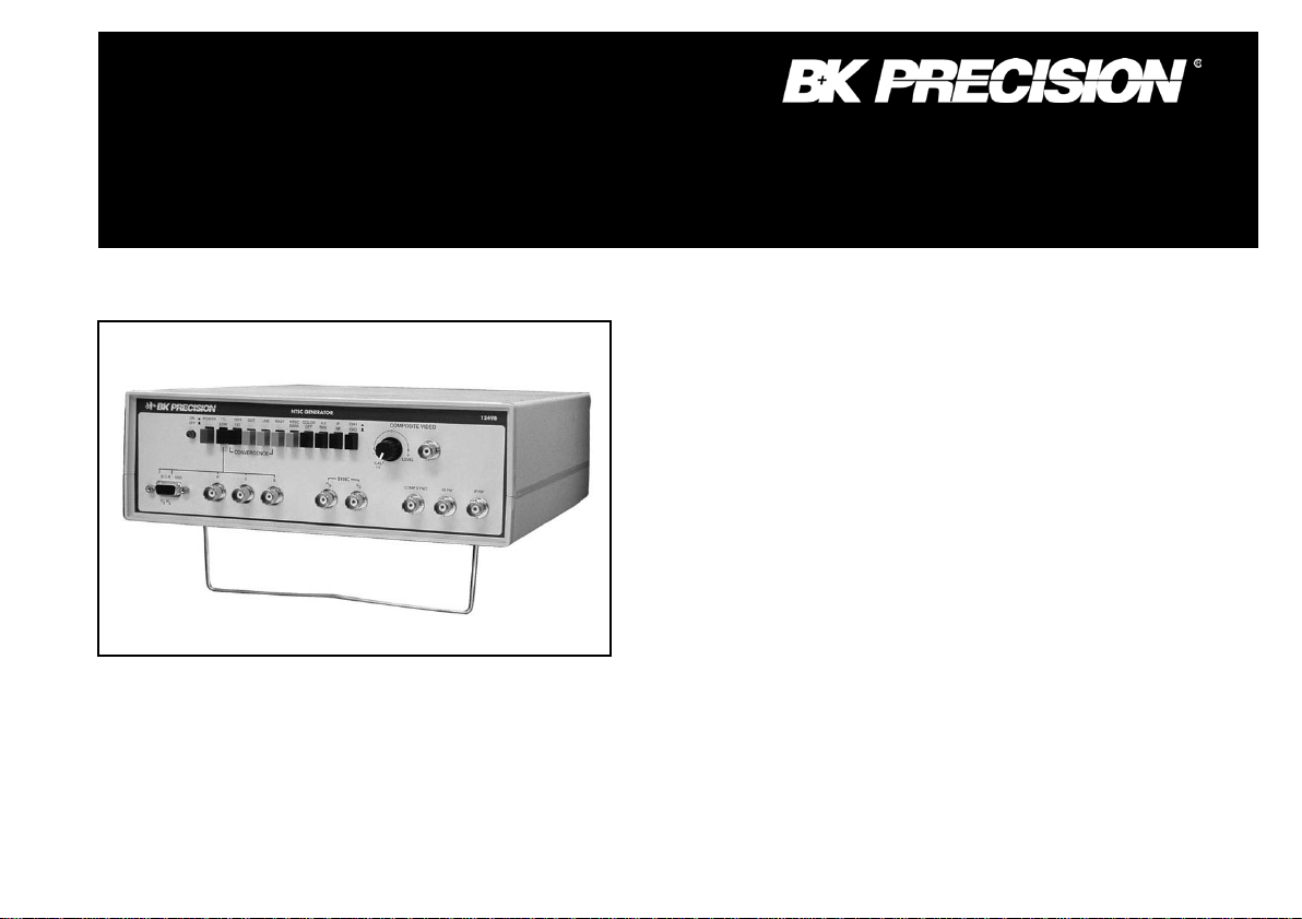
Model 1249B
INSTRUCTION
MANUAL
NTSC GENERATOR
Page 2

2
WARNING
TEST INSTRUMENT SAFETY
Normal use of test equipment exposes you to a certain amount of danger from electrical shock because testing must sometimes be performed
where exposed voltage is present. An electrical shock causing 10 milliamps of current to pass through the heart will stop most human
heartbeats. Voltage as low as 35 volts dc or ac r ms should b e considered danger ous and hazardous si nce it can pr oduce a lethal current under
certain conditions. Higher voltages p ose an even greater threat because such voltage can more easily produce a lethal current. Your normal
work habits should include all accept ed practices to prevent contact with exp osed high voltage, and to steer current awa y from your heart in
case of accidental contact with a high volt age. You will significant ly reduce the risk factor if you know and observe the following saf ety
precautions:
1. Connect the NTSC Generator’s ac power cord only to a 3-wire outlet to assure that the instrument’s chassis and gro und l eads or probes
ore test cables are at earth ground.
2. Don't expose high voltage needlessly to the equipment under test. Remove housings and covers only when necessary. Turn off equipment
while making test connections in high-voltage circuits . Dischar ge high-voltage capacitors after removing power.
3. If possible, familiarize yourself with the equipment being tested and the locati on of its high voltage points. However, remember t hat hi gh
voltage may appear at unexpected points in defective equipment.
4. Use a n insulated floor material or a large, insulated floor mat to stand on, and an insulated work surface on which to place equipment;
and make certain such surfaces are not damp or wet.
5. Use the time proven "one hand in the pocket" technique while handling an instrument pr obe. Be particularly car eful to avoid contacting a
nearby metal object that could provide a good ground return path.
6. When testing video equipment t hat includes a picture tube or CRT, remember that the high voltage power supply and CRT anode op erate
at very high voltage, often 20,000 volts or more. Carefully void these ar eas when the equipment is operating. It is also typical for thes e
circuits to retain a high voltage charge long after the equipment is turned off. Before attempting any servicing with the power removed,
discharge high voltage pints. Also avoid bumping the CRT with a sharp edge. Because of the high vacuum, a nicked CRT may “implode”
and cause flying glass fragments.
(continued on inside rear cover)
Page 3

3
TABLE OF CONTENTS
Page
Page
TEST INSTRUMENT SAFETY ............................. inside front cover
INTRODUCTION ........................................................................4
FEATURES .......................................................................................... 5
SPECIFICATIONS .............................................................................. 6
DEFINITIONS OF TERMS ................................................................ 8
THE NTSC COLOR VIDEO SIGNAL ............................................ 11
History ......................................................................................... 11
Horizontal Sync ........................................................................... 11
Vertical Sync ............................................................................... 12
Amplitude .................................................................................... 12
Color ............................................................................................ 15
NTSC Color Bars Signal ............................................................. 15
CONTROLS AND INDICATORS ................................................... 18
OPERATING INSTRUCTIONS ....................................................... 22
Precautions and Tips ................................................................... 22
Familiarization ............................................................................ 22
Initial Set-Up ............................................................................... 22
NTSC Standard Color Bar Pattern ............................................. 24
Staircase Pattern .......................................................................... 25
Color Bars With 100% White ..................................................... 25
Staircase With 100% White ........................................................ 25
Convergence Patterns .................................................................. 25
Black Raster Pattern .......................................................... 25
4.5MHz Subcarrier Use ........................................................... 25
RGB Output ............................................................................. 25
Wavef or m Mo ni tor i ng ............................................................. 26
Simultaneous Outputs .............................................................. 27
APPLICATIONS .............................................................................. 28
NTSC Color Bars ..................................................................... 28
Staircase ................................................................................... 29
Convergence ............................................................................. 29
RF and I-F ................................................................................ 29
Sync .......................................................................................... 30
30Hz Output ............................................................................. 30
CCTV Applications ................................................................. 30
CATV Applications ................................................................. 30
MATV Applications ................................................................ 31
Vectorscope Measurements .................................................... 31
MAINTENANCE ..................................................................... 34
Case Removal ......................................................................... 34
Fuse Replacement ................................................................... 34
Calibration ....................................................................... 34
SERVICE INSTRUCTIONS ...................................................... 38
LIMITED ONE- YEAR WARRANTY ....................................... 39
Page 4

4
T
it to be used to set-up and adjustment TV sets and other
carrier is
INTRODUCTION
he B+K PRECISION Model 1249B NTSC Generator is a
versatile, low cost, precision television/video signal
generator. It generates a variety of test signals and patt erns for
comprehensive testi ng, servicing, and adj ustment of video and
television equipment. Its applications include television
receivers, video tape recorders, closed circuit television
systems and components, and master antenna systems and
components, as well as most standard computer and video
monitors.
The instrument can generate many different patterns, each of
which is available as a composite video signal or a modulated
rf output on channel 3, channel d, or the standard television i-f
frequency of 45.75MHz. This provides the proper signal for
injection at a ny point in the equipment.
The video patterns include standard NTSC color bats with
standard 75 % white or wit h 100% whit e, stair case, blac k raster,
and an assortment of convergence patterns. An engineer or
technician with a good knowled ge of vid eo ci rcui ts ca n us e th e
variety of patterns to analyze and isolate almost any video
problem.
The NTSC Color Bars signal generated by the instrument is
the same type of color bar signal that is used by the television
equipment for the best performance. This is not possible
with lower cost gated rainbow color generators, which
produce a signal unlike that used dur i ng normal op eration.
Separate RGB and sync outputs are available for use with
most computer and video monitors using standard 525 li ne.
15.750KHz scan. The inputs to these RGB monitors are
separate digital signals for red, green, a nd blue, and s eparate
digital composite sync or separate digital vertical and
horizontal sync. The s ignal level a t the RGB out puts is swit ch
selectable between TTL and low (0.8V). The D-type
subminiature connector is directly comparable with IBM
Model 5153 PC monitors (TTL signal level should be
selected for use with the IBM P C monitor).
Other features include a crystal generat ed 30Hz TTL output
and a switchable 4.5MHz s ound sub-carver modulated with
a 1 kHz audi o tone. The 30Hz signal is useful for isolati ng
servo problems in video cassette recorders.
The switch selectable 4.5MHz sound submodulated by a 1KHz tone and is used to check the sound
circuits and audio/video isolation.
Page 5

5
FEATURES
NTSC COLOR BAR S
Generates standard NTSC color bars pattern (eight bars of
standard EIA colors) at NTSC prescribed luminance and
chrominance levels and phase.
SELECTABLE COLOR
Color can be switched on or off.
CONVERGENCE P ATTERN S
Dots, crosshatch, center dot, and cent er cross patterns for
static and dynamic convergence.
BLACK RASTE R
Provides sync and reference black f or a clear blemish-free
raster.
CRYSTAL OSCILLATORS
IF, CH 3, C H 4. 30Hz. and sync generation are c rystal controlled for frequency acc urac y and stabi lit y.
COMPOSITE VIDEO OUTPUT
Composite video output wit h variabl e 0 to ± 1V p-p amp litude
into standard 75Ω impedance. Calibrated 1V p-p with
negative
sync.
RF OUTPUT
Standard 75Ω out p ut modulat ed by composi te video a t
10mV rms on channel 3, channel 4, or 45.75MHz i-f.
SYNC PULSE OUTP UTS
All outputs can be used simultaneously for maximum
flexibility. Permits more complementary testi ng or
multiple independent usage of instrument.
RGB OUTPUTS
Digital red, green and blue (RGB) signals for computer and
video monitors with sta ndard 525 line, 15.750KHz scan. D Type sub-miniature c onnector provides r ed, green, blue,
horizontal sync, and vertical sync signals and is IBM M odel
5153 PC monitor c omp atible. Output level is switch
selectable between TTL and L OW (0.8±0.2V).
30Hz OUTPUT
30Hz TTL output is useful for video recorder app licat i ons.
4.5MHz SOUND S UB-CARRIER
4.5MHz subcarrier modulat ed wit h 1KHz audio tone can be
switched on to check sound and verif y pict ure and sound
isolation.
 Loading...