

Page 1

Hot Case Series
SERIES: WDCG
Operation Manual
Page 2

2812 Grandview Drive • Simpsonville, SC 29680 • USA
(864) 963-3471 • Toll Free: (800) 927-6887 • Fax: (864) 963-5316
WHAT IS
WHO IS
COVERAGE PERIOD
WARRANTY COVERAGE
EXCEPTIONS
EXCLUSIONS
INSTALLATION
REPLACEMENT PARTS
COVERED
COVERED
This warranty covers defects in material and workmanship under normal use, and applies only to the
original purchaser providing that:
អ The equipment has not been accidentally or intentionally damaged, altered or misused;
អ The equipment is properly installed, adjusted, operated and maintained in accordance with national
and local codes, and in accordance with the installation and operating instructions provided with this
product.
អ The serial number rating plate affixed to the equipment has not been defaced or removed.
This
warranty
purchased
អ Warranty claims must be received in writing by BKI within one (1) year from date of
installation or within one (1) year and three (3) months from data of shipment from the
factory, whichever comes first.
អ COB Models: One (1) Year limited parts and labor.
អ COM Models: Two (2) Year limited parts and labor. COM convection ovens also have a two (2)
year door warranty.
អ Warranty period begins the date of dealer invoice to customer or ninety (90) days after
shipment date from BKI, whichever comes first.
This
authorized
performed during regular, weekday business hours.
Any exceptions must be pre-approved in advance and in writing by BKI.
អ Negligence
អ Thermostat calibrations
អ Air and gas
អ Light
អ Glass doors and
អ Fuses,
អ Adjustments
អ Tightening
អ Failures
អ Unauthorized
អ Damage
អ Alteration,
អ Thermostats
អ Freight –
អ Ordinary
អ Failure to follow
អ Events
Leveling, as well as
installation
BKI genuine
installation
for use in the U.S.A.
warranty
covers on-site labor, parts and
service
representative
or acts of
adjustments,
bulbs,
caused
beyond control
door adjustments,
to
burner
of screws or
by erratic
repair by
in
shipment,
misuse or
other than normal UPS charges,
wear and
and use materials – is the responsibility of the
Factory OEM parts receive a (90) day
by a BKI F
improper installation,
and safety valves with
tear,
installation and/or operating instructions,
proper installation
actory Authorized
is
extended
God,
after (30) days
flames and
fasteners,
voltages
anyone other than
of the
to the original
up to (100) miles
cleaning of
or gas
broken
company.
and check out of all
Service
purchaser
reasonable
from equipment installation date,
round
pilot
burners,
suppliers,
a BKI F
actory Authorized
capillary tubes,
materials warranty
Center.
and applies only to
travel
time
trip and (2)
new equipment -
dealer
and travel e
or installer, not the
hours
Service Center,
effective from the date of
equipment
xpenses
travel time and
per
appropriate
of the
manufacturer.
Warranty
part. BKI shall in no
excess of the
all
BKI Worldwide, Inc. is a wholly owned subsidiary of Standex International Corporation.
is in lieu of all
purchase
obligations under
other warranties, expressed
event
be liable for any
price of the unit. The repair or
the terms of this
special, indirect
warranty.
or implied, and all
or
consequential damages,
replacement
of
other obligations
proven defective
or liabilities on the
or in any
parts shall
event
constitute a
manufacturer’s
for
damages
fulfillment of
SM-OM-012.02 Revised 01/05/17
in
Page 3

Table of Contents
Tab
le of Contents ........................................................................................................................................ 1
Introduction ................................................................................................................................................. 2
Safety Precautions .................................................................................................................................... 2
Operation ..................................................................................................................................................... 5
Controls and Indicators .............................................................................................................................
Preheating ................................................................................................................................................. 8
Temperature Adjustment .......................................................................................................................... 8
Operational Guidelines ............................................................................................................................. 8
Unit Shutdown........................................................................................................................................... 8
Installation ................................................................................................................................................... 9
Unpacking and Handling ........................................................................................................................... 9
Floor Model ............................................................................................................................................... 9
Pedestal Model ....................................................................................................................................... 12
Counter Model ........................................................................................................................................ 13
Front Glass Adjustment .......................................................................................................................... 13
Wiring ...................................................................................................................................................... 14
Case Joining Trim ................................................................................................................................... 15
Case Divider Glass ................................................................................................................................. 16
Maintenance .............................................................................................................................................. 17
Scheduled Maintenance ......................................................................................................................... 17
Well Numbering Convention ................................................................................................................... 18
Troubleshooting ...................................................................................................................................... 18
Wiring Diagrams ....................................................................................................................................... 20
Notes ............................................................................................................................................................ 1
5
1
Page 4
Introduction
PLEASE READ THIS ENTIRE MANUAL BEFORE SERVICING THE UNIT. If you
have any questions, contact the BKI Technical Service Department, toll free:
1-800-927-6887. Outside the U.S., call 1-864-963-3471.
This unit is to be sealed to the floor after installation to conform to NSF
requirements. (Dow Corning RTV #732 Multi purpose Sealant.)
Congratulations on your purchase of a BKI® WDCG Hot Case.
Safety Precautions
lways follow recommended safety precautions listed in this manual. Below is the safety alert symbol.
A
When you see this symbol on your equipment, be alert to the potential for personal injury or property
damage.
Safety Signs and Messages
The following Safety signs and messages are placed in this manual to provide instructions and identify
specific areas where potential hazards exist and special precautions should be taken. Know and
understand the meaning of these instructions, signs, and messages. Damage to the equipment, death or
serious injury to you or other persons may result if these messages are not followed.
This message indicates an imminently hazardous situation which, if not avoided,
will result in death or serious injury.
This message indicates a potentially hazardous situation, which, if not avoided,
could result in death or serious injury.
This message indicates a potentially hazardous situation, which, if not avoided,
may result in minor or moderate injury. It may also be used to alert against unsafe
practices.
This message is used when special information, instructions or identification are
required relating to procedures, equipment, tools, capacities and other special
data.
2
Page 5

Specific Precautions
Equipotential Ground Plane
When a high current flows through a conductor, differences in potential appear
between the conductor and nearby metallic surfaces near the appliance. As a
result, sparks may be produced between the appliance and surrounding metal
surfaces. These sparks could cause serious injury, damage, or fire.
BKI provides an Equipotential ground terminal for the connection of a bonding
conductor after the installation of the appliance per lEC60417-1. This terminal is
located on the inside of the Power Entry Supply box near the Earth connection
and is marked with this symbol.
Safe Work Practices
Beware of High Voltage
This equipment uses high voltage. Serious injury can occur if any
untrained or unauthorized person installs, services, or repairs this
equipment. Advise your customer to always use an Authorized
Service agent to Service this Equipment
Your Customer Should have an Operators Manual
The operators manual is an important part of this equipment. Your
customer should keep it near for easy access.
If your customer needs a replacement operators manual, contact:
BKI
Technical Services Department
2812 Grandview Drive
Simpsonville, S.C. 29680
Or call toll free: 1-800-927-6887
Outside the U.S., call 864-963-3471
3
Page 6

Safety Labels Must be Clean and in Good
Condition
Make sure all safety labels are in place, clean and in good condition.
Replace any damaged or missing safety labels.
If you need new safety labels, contact:
BKI
Technical Services Department
2812 Grandview Drive
Simpsonville, S.C. 29680
Or call toll free: 1-800-927-6887
Outside the U.S., call 864-963-3471
4
Page 7
Item #
Description
Function
Operation
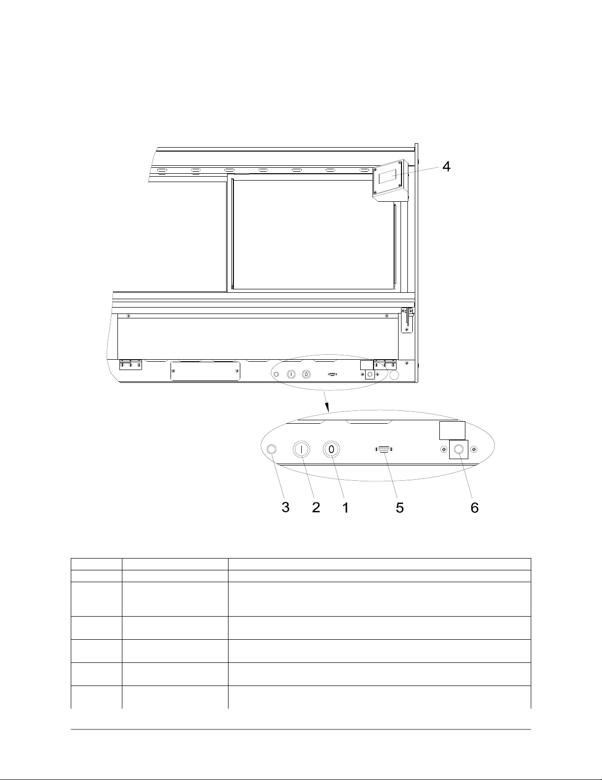
Controls and Indicators
The deli case controls are shown in the figure below. The pushbutton switches turn the power supply to
the case on and off. The touchscreen interface is used to operate the case and display temperatures.
WHEN LIT
ADD
WATER
WHEN LIT
ADD
WATER
Hardware Controls
1 Power OFF Switch Depressing the switch turns power OFF to the entire unit.
2 Power ON Switch Depressing the switch turns power ON to the entire unit. When the
unit is ON the touchscreen controller is powered & the lights
illuminate.
3 Main Power Isolator
Light
4 Analog Touchscreen
Interface
5 Controller RS-232
Interface
6 Water Level Indicator (Optional) This light illuminates when the water level in the optional
This light illuminates to indicate that power is being applied to the
unit from the main power isolator (circuit breaker).
Used for the operation of the unit and to measure & record product
temperatures.
Allows user to download saved product temperatures to a laptop
PC using the supplied software. Optional food probe required.
humidity water pan is low to indicate to add more water to the pan.
5
Page 8
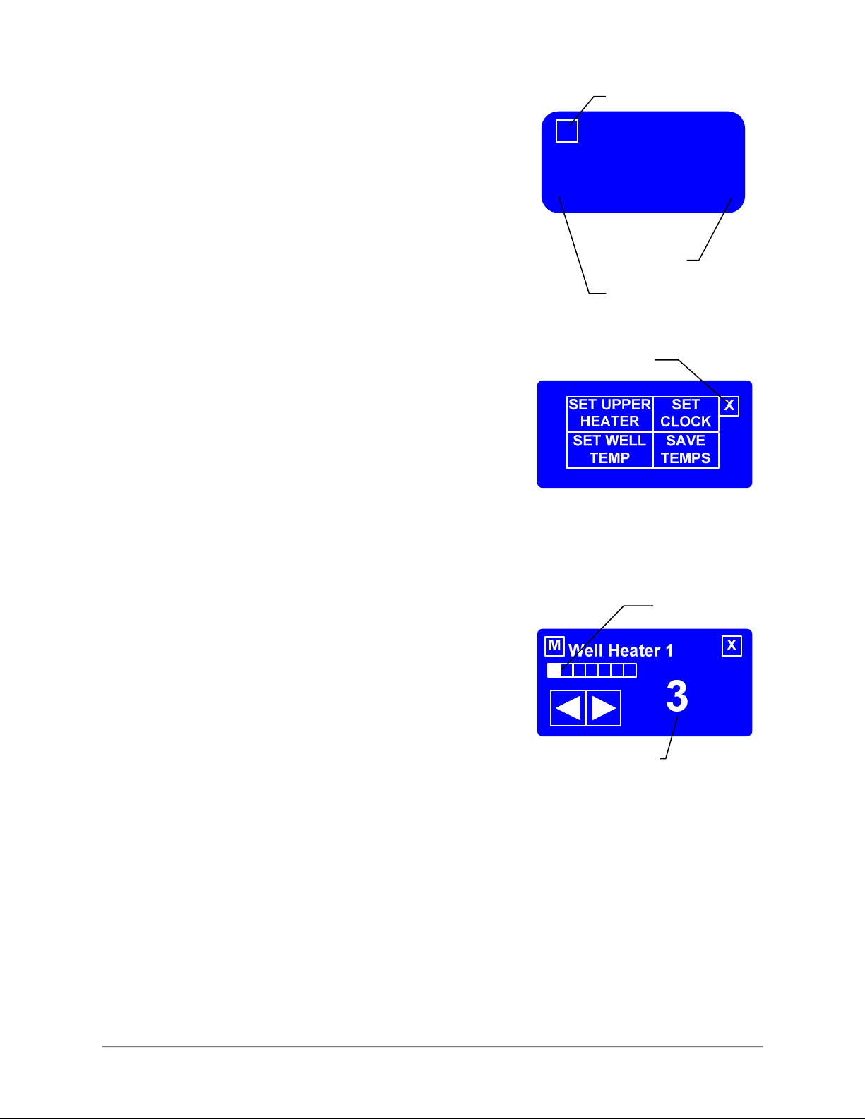
Software Controls - Default Screen
M
Lower Right
Lower Left
The Default Screen appears on the touchscreen during normal
operation. The screen shows the menu button and the heating
status of the unit.
When the unit is first powered up, “Warming” will be displayed.
When the unit reaches operating temperature, “Ready” will be
displayed as shown at the right.
If the display does not change from “Warming” to “Re
45 minutes there is a problem with the unit. A qualified BKI
service representative should be contacted.
ady” after
Software Controls - Viewing Settings
The current heater settings can be viewed by touching the Menu
Button [M] on the Default Screen. The Menu Screen will then be
displayed.
To view the current settings for either Well Temp or Upper Heater
touch the appropriate button on the Menu Screen. The View
Setting Screen for the selected heaters will be displayed.
Menu Button
Ready
Default Screen
Exit Button
To return to the Default Screen, touch the Exit Button [X].
If the controller is configured to control each well position
independently the View Setting Screen as shown at right will be
displayed. Use the left and right arrows to display the heater
setting for the various well positions of the unit. The progress bar
gives a visual representation of the well location for which the
setting is being displayed.
The current heater setting is displayed on the right side of the
screen. The setting is a numeric value between 1 and 10 where
10 is the hottest setting.
If the controller is configured to control all of the well positions at
the same setting, the progress bar will be solid and the left and
right arrows will not be displayed. The setting shown will be for
the heaters at all of the well positions.
To return to the Menu Screen, touch the Menu Button [M]. To
return to the Default Screen, touch the Exit Button [X].
Touching [Set Clock] on the Menu Screen will display the time
and date. To return to the Menu Screen, touch the Menu Button
[M]. To return to the Default Screen, touch the Exit Button [X].
Menu Screen
Progress Bar
Current Setting
View Setting Screen
Software Controls - Programming the
6
Page 9
M
Lower Left
Lower Right
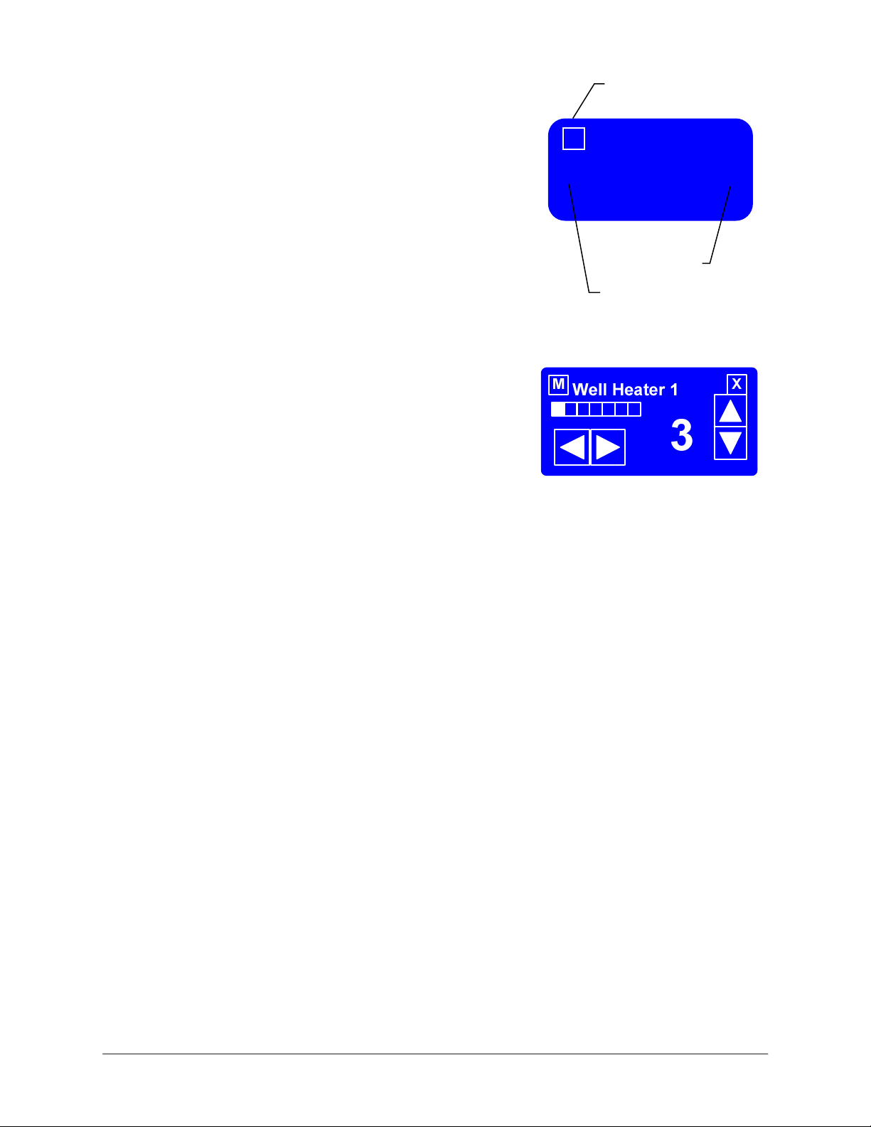
Controller
There is a unique set of touches to enter the programming mode.
This prevents the case settings from being inadvertently
changed.
Enter the programming mode from the Default Screen by
touching the lower left of the touchscreen, then the lower right
and then the Menu Button [M] in that order. The Menu Screen
will then be displayed.
To edit the current settings for either Well Temp or Upper Heater
touch the appropriate button on the Menu Screen. The Edit
Setting Screen for the selected heaters will be displayed.
To return to the Default Screen, touch the Exit Button [X].
If the controller is configured to control each well position
independently the Edit Setting Screen as shown at right will be
displayed. Use the left and right arrows to display the heater
setting for the various well positions of the unit. The progress bar
gives a visual representation of the well location for which the
setting is being displayed.
The current heater setting is displayed on the right side of the
screen. Use the up and down arrows to edit the heater setting.
The setting is a numeric value between 1 and 10 where 10 is the
hottest setting.
If the controller is configured to control all of the well positions at
the same setting, the progress bar will be solid and the left and
right arrows will not be displayed. Use the up and down arrows
to edit the heater setting for all of the well positions.
To return to the Menu Screen, touch the Menu Button [M]. To
return to the Default Screen, touch the Exit Button [X].
To edit the controller time and date settings touch [Set Clock] on
the Menu Screen while in the program mode. The time and date
will need to be reset if the power supply to the case has been
disconnected.
Use the left and right arrows to move the cursor under the value
to be edited. Use the up and down arrows to edit the value.
Continue until the current date and time is displayed.
To return to the Menu Screen, touch the Menu Button [M]. To
return to the Default Screen, touch the Exit Button [X].
Menu Button
Ready
Default Screen
Edit Settings Screen
7
Page 10

Preheating
You should allow the equipment to preheat at the programmed temperature settings for a minimum of 30
minutes before loading it with product. For initial start up, program the controller for each well heater to a
setting of 7 and each upper heater to a setting of 5.
If equipped with the optional humidity water pan, fill the pan with 6 quarts (5 1/2 liters) of water before
preheating the equipment.
Check Federal and State Health and Sanitation Regulations for internal temperature required for holding
cooked foods for sale. Maintaining these temperatures often tend to allow continued cooking of certain
products. Therefore, smaller amounts of bulk foods should be displayed at non-peak periods and the
warmer refilled as needed.
All meats and vegetables should be preheated to 160°F (70°C). before being placed in the case.
A screen liner can be used in the bottom of the display pans that are used for holding meats. This will
keep meats from sticking to the bottom of the pans.
Temperature Adjustment
After placing the product into the equipment, it may be necessary to adjust the programmed settings in
order to maintain the proper internal temperature for the product on display. The optional built-in product
temperature probe or a portable meat thermometer should be used to read the internal temperature of
each product. The programmed settings should be set to the lowest possible number that will maintain
the proper product temperature.
Operational Guidelines
Keep the optional built-in product temperature probe or a portable meat thermometer on hand. Check the
food temperatures hourly.
Rotate the food products. Foods loaded in first should be served first as much as is practical.
Foods held for long periods of time are more difficult to maintain at proper temperature. Also, freshness
and product quality diminish if foods are held too long. Most areas of the country have sanitation
regulations governing how long foods can be held. Make certain to check with your local authorities.
If equipped with the optional humidity water pan, add 4 quarts (4 liters) of water to the water pan when the
“Add Water” indicator lamp illuminates. If equipment has the remote water fill tube on the back of the
counter top add water through this tube. Otherwise, it will be necessary to remove a food pan above the
water pan to add water.
Unit Shutdown
Remove all food pans holding the food product from the equipment. Depress the OFF pushbutton switch
to turn the power to the heaters and lights off. After the temperature has cooled below 120°F (50°C),
remove any residue from the wells and clean the equipment thoroughly.
8
Page 11

Installation
Serious injury, equipment damage or death could result if attempting to install
this unit yourself. Ensure that an authorized BKI service agent installs the unit.
Unpacking and Handling
The company taking delivery of this equipment is responsible for filling all freight claims with the delivering
truck line. Inspect all cartons and crates for damage as soon as they arrive. If damage to cartons or
crates is found, or if a shortage is found, note this on the bill of lading (all copies) prior to signing.
If damage is found when the equipment is opened, immediately call the delivering truck line and follow up
the call with a written report indicating concealed damage to your shipment. Ask for an immediate
inspection of your concealed damage item. Packaging material MUST be retained to show the inspector
from the truck line.
Do not walk on top of deli cases or damage to the cases and serious personal
injury could occur. The cases are not structurally designed to support excessive
external loading such as the weight of a person. Do not place heavy objects on
the deli cases.
Move the deli case as close as possible to its permanent location before moving the case off of the
shipping pallet. Shipping braces are installed on each end of the deli case. Leave these braces in place
while moving and leveling the deli case.
Make certain there are no separately packed accessories before discarding packaging.
During shipment, the lubricant in the gas springs may have settled. This can cause the glass not to
remain open in the raised position. To avoid this, fully raise and lower the glass manually 4 or 5 times.
This unit is designed to be sealed to the floor after it is installed – to conform to
NSF Standard 4. Use Dow Corning RTV # 732 Multi-purpose Sealant.
Floor Model
Leveling
Deli cases must be installed level to insure proper operation and alignment to adjoining equipment. Use a
carpenter’s level as shown in Figure 1. Begin lineup leveling from the highest point of the store floor.
1. Level the case using the leg levelers at the corners of the case (Figure 1).
2. Raise the low end of the case, do not lower the high end.
3. Check for level side-to-side and front-to-back.
4. If you are installing adjoining cases, position the next case in line beside the level case and
proceed to the next step.
5. Level this case in the same manner.
6. When level, bolt the two cases together at the locations shown in Figure 1.
NOTE: None of the end components shown in Figure 2 should be attached to adjoining case
ends
If the cases have been properly leveled, the front panels and counter tops should align with a
small, uniform gap between the front panels of the two cases.
7. Proceed in the same manner until all the cases in the line are level and bolted together.
9
Page 12
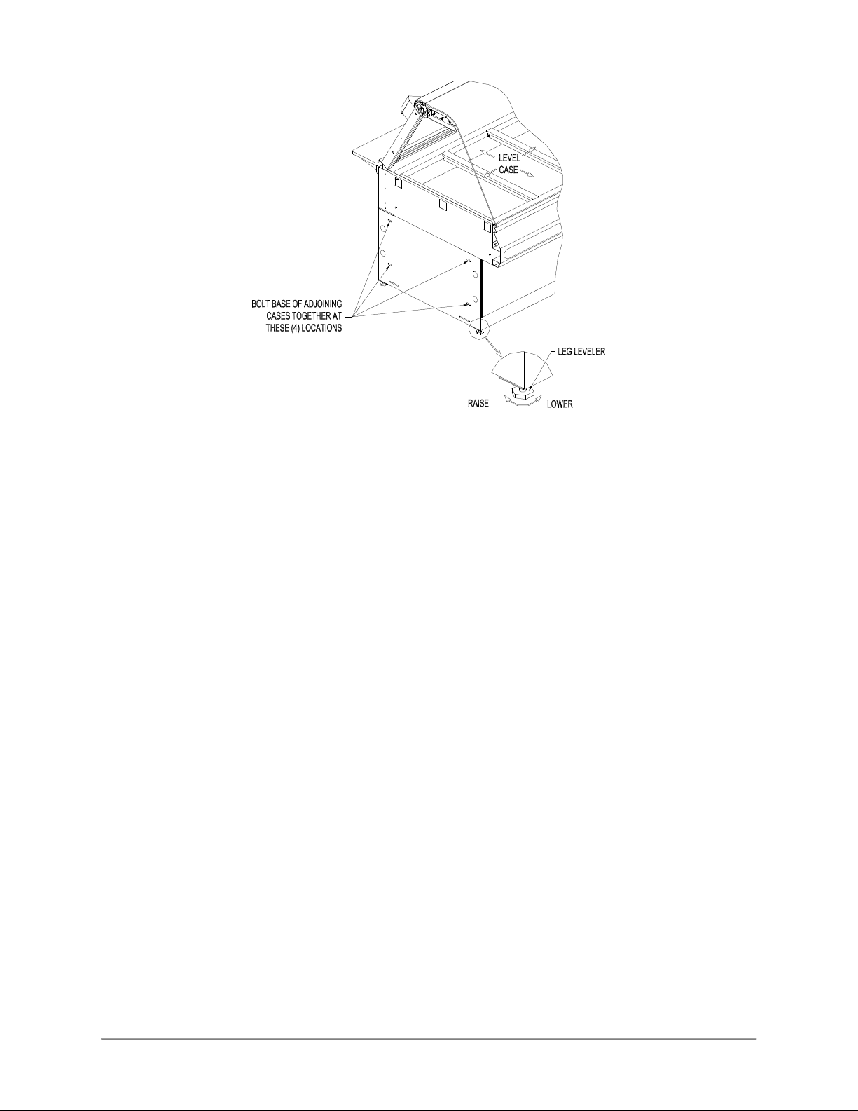
Figure 1. Floor Models - Leveling
Kick Plate Mounting
A black vinyl-covered kick plate is provided for the front, back and ends of each case.
1. In order to install the Kick Plates it will be necessary to remove the End Trim Panels (see
Figure 2). Remove the retaining nuts located inside the base with a 3/8” wrench. From
outside of the case pull the End Trim Panels away from the case.
2. Slide the front kick plate (the wider of the two) behind the lower finished front panel of the case
(see Figure 2).
3. Make certain that the ends of the kick plate are flush with the ends of the lower finished front
panel and that the kick plate is flush to the floor.
4. Drill 5/32” diameter holes in the case base to match the pre-drilled holes in the kick plate.
5. Attach the kick plate to the case base with the black sheet metal screws provided.
6. Mount the back kick plate to the case in the same manner.
7. Set the End Kick Plates into position on the ends of the case flush with the floor (see Figure 2).
NOTE: There are left and right hand End Kick Plates. The longer end flange faces toward the front of
the case with the black side out. The End Kick Plates fit over the ends of the front and back kick
plates and flush to the floor.
8. Carefully slide the End Trim Panels back into position on the case and push and reinstall the
retaining nuts.
9. This unit is designed to be sealed to the floor after it is installed – to conform to NSF Standard 4.
Use Dow Corning RTV # 732 Multi-purpose Sealant or equivalent silicone sealant to seal the Kick
Plates to the floor around the full perimeter of the case.
10
Page 13

End Panel Mounting
Attach the End Panels to the ends of the case(s) as shown in Figure 2 using the shoulder screws
provided. For Glass End Panels only, slide the plastic bushings provided over the shoulder screws
before inserting the screw into the glass panel. Be careful that the screws do not bind in the holes in
the glass panel.
Figure 2. Floor Model - End Kick Plate & End Panel Mounting
11
Page 14

Pedestal Model
Leveling
Deli cases must be installed level to insure proper operation and alignment to adjoining equipment. Use a
carpenter’s level and begin leveling from the highest point of the store floor.
1. Level the case using the leg levelers at the corners of the pedestals (see Figure 3).
2. Raise the low end of the case to level it, do not lower the high end.
3. Check for level side-to-side and front-to-back.
Figure 3. Pedestal Model - Leveling and Cover Attachment
Pedestal Wrap Installation
1. Remove the Rear Trim from the back of each Pedestal by removing the (4) retaining screws on
each Rear Trim.
2. Spread the side panels of the Pedestal Wraps apart far enough to fit around Pedestal and slide
the Pedestal Wrap around the Pedestal from the front as shown in Figure 3. Make certain the
Pedestal Wrap fits flush to the floor.
NOTES: There are left and right hand Pedestal Wraps. The taller side panel on each Pedestal
Wrap is oriented to the end of deli case.
The short return flange on the front of each Pedestal Wrap side Panel will insert into the large cut
out in the front of the Pedestal. The back flange of each Pedestal Wrap side Panel will wrap
around the back of the Pedestal.
12
Page 15

3. Place the Rear Trim in position on the back of each Pedestal. The Pedestal Wraps fit inside of
the side flanges of the Rear Trim. Thread the Rear Trim retaining screws into the J nuts on the
Pedestal. Make certain the Rear Trim is flush with the floor and tighten the retaining screws.
The Pedestals are to be sealed to the floor if required by local health codes. Seal the pedestal
covers to the floor using a silicone-type sealant (Dow Corning RTV #732 or equivalent).
End Panel Mounting
Attach the End Panels to the ends of the case(s) as shown in Figure 2 using the shoulder screws
provided. For Glass End Panels only, slide the plastic bushings provided over the shoulder screws
before inserting the screw into the glass panel. Be careful that the screws do not bind in the holes in
the glass panel.
Counter Model
Counter Mounted cases must be mounted on a level surface that can support the weight of the case and
it contents. Use a carpenter’s level as shown in Figure 1 to level the case.
These cases are to be sealed to the counter if required by local health codes. Seal the perimeter of the
case to the counter using a silicone-type sealant (Dow Corning RTV #732 or equivalent).
Attach the End Panels to the ends of the case as shown in Figure 2 using the shoulder screws provided.
For Glass End Panels only, slide the plastic bushings provided over the shoulder screws before inserting
the screw into the glass panel. Be careful that the screws do not bind in the holes in the glass panel.
Front Glass Adjustment
During shipment, the lubricant in the gas springs may have settled. This can cause
the glass not to remain open in the raised position. To avoid this, fully raise and
lower the glass manually 4 or 5 times
Alignment of the front glass(es) may change during shipment and installation. After the case is in its final
location and leveled check the distance between
the ends of the glass(es) and the end panels.
On single front glass cases the distance between
each end of the glass and the end panels should
be the same.
On cases with two front glasses the space at the
joint between the two glasses and the distance
between the glass ends and the end panels
should all be the same.
HINGE ELEMENT
CLAMP SCREW
The front glass spacing can be adjusted by
raising the front glass(es) and loosening the
hinge element clamp screws on all of the front
glass hinge elements using a 4 mm hex wrench.
(Refer to the illustration on the right.)
SNEEZE GLASS
ADJUSTMENT SCREW
Move the glass as required and tighten the
clamp screws. Close the front glass(es) to verify the spacing. If necessary repeat the procedure above
until the proper glass alignment is achieved.
The height of the partial sneeze glass on self-service cases can be adjusted using the adjustment
screw(s) located in front of the glass hinge element(s). Raise or lower the screw to make the top of the
sneeze glass horizontal or align it with adjoining glasses.
13
Page 16

Wiring
A wiring diagram for the specific model is shipped with the deli case. The wiring diagram provides
electrical specifications, an electrical schematic and a parts list. Refer to this wiring diagram and the deli
case serial number plate for electrical information.
Field wiring must be sized for the components amperes printed on the serial number plate. Actual ampere
draw may be less than specified.
All electrical connections should be in compliance with the NEC and all applicable local codes by a
licensed electrician. Refer to the wiring diagram furnished with your case for the electrical specifications.
The power supply connection is located on the bottom or back of the well compartment of the case (see
Figure 4). A ¾ knockout is provided at each location for the required conduit connection. A second power
supply connection for the oven is provided on oven combo cases.
A wiring cutout is provided in the base bottom pan on floor model cases (see Figure 5). Refer to the case
specification sheet for the location of this cutout. Remove the cover over the wiring cutout and route the
wiring through the cutout. Cut a hole of the proper size and location in the cover for the conduit to pass
through and reinstall the cover.
Figure 4. Wiring Access
14
Page 17

Case Joining Trim
1. After leveling the cases and bolting the bases together, bolt the canopies together as shown in
Fig. 6 with a ¼”-20 x ¾” Hex Head Screw and Keps Nut.
2. Mount the Upper Front & Base Front Joint Trims by holding them in place and marking the hole
locations on the case.
3. Make certain the joint covers are centered on the joint and that they align vertically with each
other.
4. Drill the case holes 5/32” and attach joint covers with screws provided. Before tightening the top
screws of the Upper Front Trim, slide the Counter Front Trim in place between the screw head
and the Upper Front Trim.
5. Apply a bead of silicone sealant inside the Counter End Joint Cover and slide the cover over both
counter end walls. Apply a bead of silicone sealant to seal the open front of the Counter End
Joint Cover.
6. Attach Bumper Ends and Bumper Mounting Base to the front of the cases, centered on the
vertical surface of the upper front of the case. Cut the Bumper Top to length to fit between the
Bumper Ends and snap into place.
Figure 5. Joining Cases
15
Page 18

Case Divider Glass
A Divider Glass is typically installed between a self-service case with reach-in front glass and a full
service case with full front glass. The Divider Glass is installed on the full service case side of the joint.
1. Mount the Upper Glass Retainer by first removing the outer (2) retaining screws from the canopy
heater reflector on the end of the deli case the Divider Glass is being installed. Insert the screws
through the outer set of holes in the Upper Glass Retainer (see Figure 6) and attach the Upper
Glass Retainer to the canopy.
2. Place the Lower Glass Retainer in position against the inside of the counter end wall on the end
of the deli case the Divider Glass is being installed. The side of the Lower Glass Retainer with (2)
vertical walls is placed against the counter end wall.
3. Apply a bead of silicone sealant inside the Counter End Joint Cover and slide the cover over both
counter end walls and the Lower Glass Retainer. Apply a bead of silicone sealant to seal the
open front of the Counter End Joint Cover.
4. Slide Divider Glass in place through the Upper and Lower Glass Retainers.
Figure 6. Divider Glass Installation
16
Page 19

Frequency
Performed By
Part Activity
Maintenance
Failure to comply with the maintenance below could result in a serious accident.
Electrocution, equipment failure or property damage could result if an unlicensed
electrician performs electrical repair. Ensure that a licensed electrician perform
electrical repair.
Scheduled Maintenance
Use the following table to help manage scheduled maintenance activities.
Daily User Case Clean the entire Case. Refer to the
cleaning procedure below.
Cleaning
This unit should be cleaned at the end of each day. Use the following procedure:
Failure to remove power from this unit may cause severe electrical shock. This
unit may have more than one disconnect switch.
1. Turn the machine ‘off ‘ and allow it to cool down.
2. Remove any food pans.
Using abrasive cleaners may damage the cabinet finish. Use only a mild soap and
water solution.
Never steam clean or get excess water in the interior of the cabinet as this can
damage unit.
This appliance is not intended to be cleaned with a water jet.
3. Use a mild soap and water solution to clean parts.
4. Sponge the inside and outside with a mild soap and water solution.
5. Wipe the parts and cabinet dry with a soft, clean cloth.
17
Page 20

Problem
Cause
Possible Solution
Case Not Operating
Case
Not Operating
Holding Temperature Not
Individual Heating Element Not
Control displays PL# and
bee
ps
Control displays P
H
# and
bee
ps
PL and PH messages can appear shortly after case is turned ON.
Control displays
T
L# and
bee
ps
Control displays
TH
# and
bee
ps
Well Numbering Convention
Facing the case from the Customer side, Well 1 is on the far right-hand end of the case. The well number
increase sequentially from right to left.
Troubleshooting
Refer to the table below for troubleshooting information.
Disconnect the case power supply by turning OFF the circuit breaker in the power supply service panel
before performing any diagnostic testing.
No Power to the case. Check circuit breaker or fuses at
(Clear pilot light not illuminated)
Power switch is off. Reset the power switch.
(Clear pilot light illuminated)
building power panel.
Adequate
Heating
every second (# specifies
number problem well).
Control Safety Interlock
circuit has shut case off
because one of the well
temperature probes reached
a preset value.
Case and food pans have not
been preheated.
Product is below 160° F when
loaded into case.
One or more heating
elements not operating
properly.
Loose wire or bad
connection.
Failed Heating Element. Replace failed Heating Element.
Failed Output on Control
Board.
Probe low, shorted.
Measured temperature
< 40°F.
Failed temperature probe,
temperature probes not
connected to control in proper
sequence, well heating elements
not connected to control in proper
sequence.
Refer to the preheating section of
Operators Manual.
Check product temperature
before loading the case.
Troubleshoot as described below.
Identify and repair wire
connection.
Replace entire Control Board.
Replace failed temperature probe
for specified well.
Probe high, open. Measured
every second (# specifies
number problem well).
every second (# specifies
number problem well).
every second (# specifies
number problem well).
TL and TH messages will not appear until after the 20 minute stabilization period.
temperature
> 550°F.
Temperature low, well probe
temperature more than 25°F
below set point.
Temperature high, well probe
temperature more than 40°F
above set point.
Replace failed temperature probe
for specified well.
Loose wire, failed heating element,
failed controller.
18
Page 21

Touch Screen Display Not
Light
Bulb(s) Do Not Illuminate
Functioning (Properly)
Damaged communication
cable.
Replaced damaged cable.
Failed Control Touch Screen
Display.
Failed Control I/O Board. Replace failed Control I/O Board.
Failed Light Bulb(s) Replace failed Light Bulb(s)
when Power is turned On
Fuse(s) Blown Locate and correct cause, then
Failed Ballast Replace failed Ballast
Replace failed Control Touch
Screen Display.
replace blown fuse(s).
19
Page 22

Wiring Diagrams
20
Page 23

21
Page 24

22
Page 25

23
Page 26

24
Page 27

25
Page 28

26
Page 29

27
Page 30

28
Page 31

29
Page 32

30
Page 33

31
Page 34

32
Page 35

33
Page 36

34
Page 37

CP0064
PL0004
MB69008200
CONTROL PANEL, TB2
CONNECT TO DELI CASE
ON WDCG-6 & 7 CASES
SPLITTER WIRES REQ'D
35
Page 38

Notes
2812 Grandview Drive, Simpsonville, S.C. 29680, USA
http://www.bkideas.com
Made and printed in the U.S.A.
SM-OM-012.02 Revised 01/05/17
 Loading...