

Page 1
Hot Food Deli Case
MODELS WDC, TSW, TCW, SSW, CSW
Installation & Operation Manual
Serial Numbers 122556 and Higher
Page 2

WHAT IS
WHO IS
COVERED
COVERAGE PERIOD
WARRANTY
EXCEPTIONS
EXCLUSIONS
INSTALLATION
REPLACEMENT PARTS
COVERED
COVERAGE
BKI LIMITED
PO Box
963-3471 • Toll
(864)
This warranty covers defects in material and workmanship under normal use, and applies only to the original
purchaser providing that:
The equipment has not been accidentally or intentionally damaged, altered or misused;
The equipment is properly installed, adjusted, operated and maintained in accordance with national and local
codes, and in accordance with the installation and operating instructions provided with this product.
The serial number rating plate affixed to the equipment has not been defaced or removed.
This
warranty
is
in the U.S.A.
extended
80400 • Simpsonville, SC
Free: (800)
to the original
purchaser
WARRANTY
29680-0400 • USA
927-6887 • Fax: (864) 963-5316
and applies only to
equipment purchased
Warranty claims must be received in writing by BKI within one (1) year from date of installation or
within one (1) year and three (3) months from data of shipment from the factory, whichever comes
first.
COB Models: One (1) Year limited parts and labor.
COM Models: Two (2) Year limited parts and labor. COM convection ovens also have a two (2) year door
warranty.
CO1 Models: Two (2) Year limited parts and labor. Five (5) Year limited door warranty.
BevLes Products: Two (2) Year limited parts and labor.
Warranty period begins the date of dealer invoice to customer or ninety (90) days after shipment date
from BKI, whichever comes first.
This
warranty
authorized
performed during regular, weekday business hours.
Any exceptions must be pre-approved in advance and in writing by BKI. The extended door warranty on
convection ovens years 3 through 5 is a parts only warranty and does not include labor, travel, mileage or
any other charges.
covers on-site labor, parts and
service
representative
reasonable
up to (100) miles
round
travel
trip and (2)
time
and travel
hours
expenses
travel time and
Negligence
Thermostat calibrations
Air and gas
Light
Glass doors and
Fuses,
Adjustments
Tightening
Failures
Unauthorized
Damage
Alteration,
Thermostats
Freight
Ordinary
Failure to follow
Events
Leveling, as well as
installation
BKI genuine
installation
Warranty
is in lieu of all
manufacturer’s
on the
damages,
or in any
replacement
warranty.
of this
or acts of
God,
after (30) days
adjustments,
bulbs,
to
of screws or
caused
repair by
in
shipment,
misuse or
and safety valves with
– other than normal UPS charges,
wear and
beyond control
proper installation
and use materials – is the responsibility of the
Factory OEM parts receive a (90) day
by a BKI F
actory Authorized
part. BKI shall in no
event
of
proven defective
door adjustments,
burner
flames and
fasteners,
by erratic
voltages
anyone other than
improper installation,
tear,
installation and/or operating instructions,
of the
other warranties, expressed
for
damages
parts shall
from equipment installation date,
cleaning of
or gas
suppliers,
a BKI F
broken
capillary tubes,
company.
and check out of all
Service
in excess of the
materials warranty
Center.
event
be liable for any
constitute a
or implied, and all
pilot
burners,
actory Authorized
new equipment -
dealer
or installer, not the
effective from the date of
other obligations
purchase
special, indirect
price of the unit. The repair or
fulfillment of all
Service Center,
per
appropriate
obligations under
of the
manufacturer.
or liabilities
or
consequential
the terms
for use
Asia Europe Latin America North America
Page 3

Hot Food Deli Case Table of Contents
Table of Contents
Table of Contents........................................................................................................................................1
Introduction .................................................................................................................................................2
Safety Precautions....................................................................................................................................2
Safety Signs and Messages.................................................................................................................2
Specific Precautions.............................................................................................................................3
Safe Work Practices.............................................................................................................................3
Operation .....................................................................................................................................................5
Controls and Indicators.............................................................................................................................5
Preheating.................................................................................................................................................5
Temperature Adjustment..........................................................................................................................6
Operational Guidelines.............................................................................................................................6
Unit Shutdown...........................................................................................................................................6
Installation ...................................................................................................................................................7
Unpacking and Handling...........................................................................................................................7
Floor Model...............................................................................................................................................7
Leveling................................................................................................................................................7
Kick Plate Mounting..............................................................................................................................8
End Panel Mounting.............................................................................................................................9
Pedestal Model.......................................................................................................................................10
Leveling..............................................................................................................................................10
Front and Rear Cover Attachment .....................................................................................................11
End Panel Mounting...........................................................................................................................11
Counter Model ........................................................................................................................................12
Wiring......................................................................................................................................................12
Joining WDCTY Cases...........................................................................................................................13
Maintenance ..............................................................................................................................................14
Scheduled Maintenance.........................................................................................................................14
Cleaning .............................................................................................................................................14
Troubleshooting......................................................................................................................................15
Notes ..........................................................................................................................................................16
1
Page 4
Hot Food Deli Case Introduction
Introduction
Congratulations! You have chosen a Hot Food Deli Case that will give you many years of fine service
from the original manufacturer, BKI.
The BKI name and trademark on this unit assures you of the finest in design and engineering -- that it has
been built with care and dedication -- using the best materials available. Attention to the operating
instructions regarding proper installation, operation, and maintenance will result in long lasting
dependability to insure the highest profitable return on your investment.
PLEASE READ THIS ENTIRE MANUAL BEFORE OPERATING THE UNIT. If
you have any questions, please contact your BKI Distributor. If they are unable to
answer your questions, contact the BKI Technical Service Department, toll free:
1-800-927-6887. Outside the U.S., call 1-864-963-3471.
This unit is to be sealed to the floor after installation to conform to NSF
requirements. (Dow Corning RTV #732 Multi purpose Sealant.)
Safety Precautions
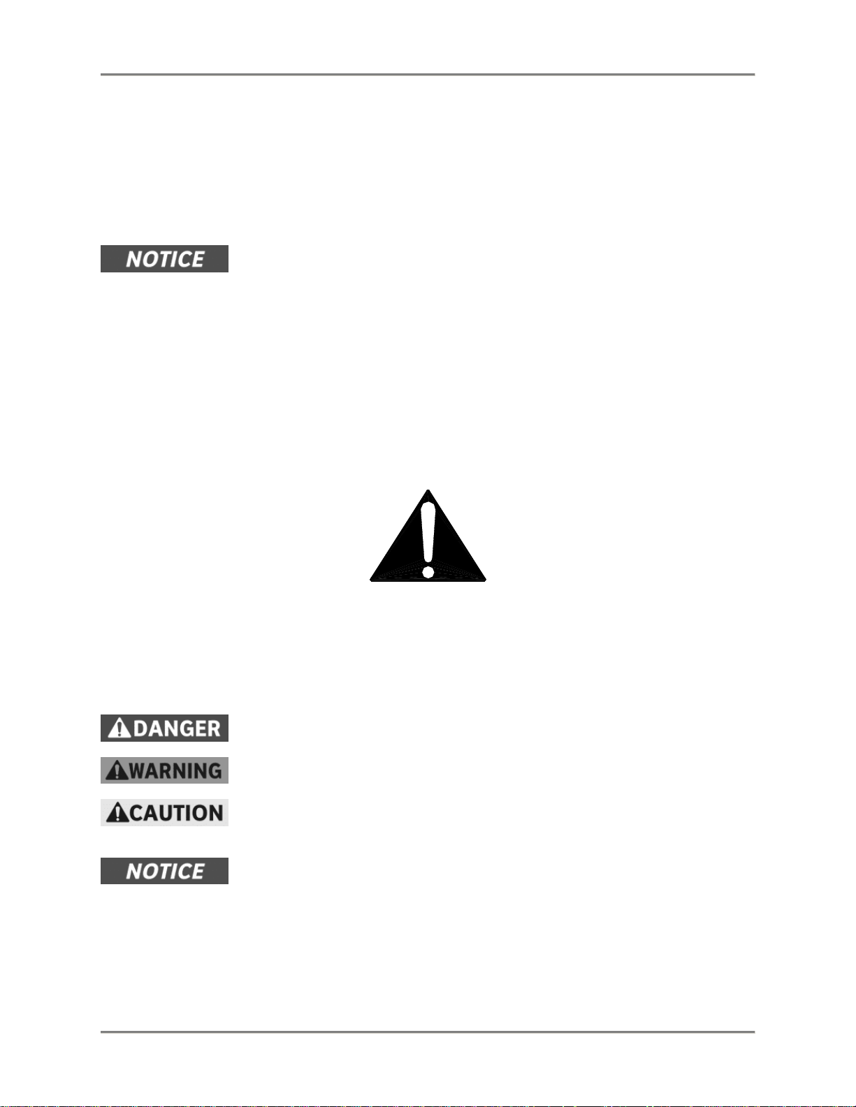
Always follow recommended safety precautions listed in this manual. Below is the safety alert symbol.
When you see this symbol on your equipment, be alert to the potential for personal injury or property
damage.
Safety Signs and Messages
The following Safety signs and messages are placed in this manual to provide instructions and identify
specific areas where potential hazards exist and special precautions should be taken. Know a nd
understand the meaning of these instructions, signs, and messages . Damage to the equipment, death or
serious injury to you or other persons may result if these messages are not followed.
This message indicates an imminently hazardous situation which, if not avoided,
will result in death or serious injury.
This message indicates a potentially hazardous situation, which, if not avoided,
could result in death or serious injury.
This message indicates a potentially hazardous situation, which, if not avoided,
may result in minor or moderate injury. It may also be used to alert against unsafe
practices.
This message is used when special information, instructions or identification are
required relating to procedures, equipment, tools, capacities and other spe cial
data.
2
Page 5
Hot Food Deli Case Introduction
Specific Precautions
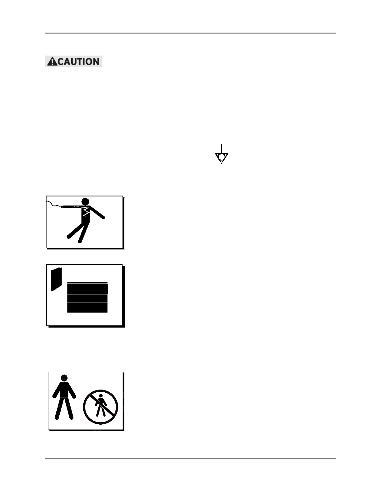
Equipotential Ground Plane
When a high current flows through a conductor, differences in potent ial appear
between the conductor and nearby metallic surfaces near the appliance. As a
result, sparks may be produced between the appliance and surrounding metal
surfaces. These sparks could cause serious injury, damage, or fire.
BKI provides an Equipotential ground terminal for the connection of a bonding
conductor after the installation of the appliance per lEC60417-1. This terminal is
located on the inside of the Power Entry Supply box near the Earth connection
and is marked with this symbol.
Safe Work Practices
Beware of High Voltage
This equipment uses high voltage. Serious injury can occur if you or
any untrained or unauthorized person installs, services, or repairs this
equipment. Always Use an Authorized Service agent to Service Your
Equipment
Keep this manual with the Equipment
This manual is an important part of your equipment. Always keep it
near for easy access.
If you need to replace this manual, contact:
BKI
Technical Services Department
P.O. Box 80400
Simpsonville, S.C. 29680-0400
Or call toll free: 1-800-927-6887
Outside the U.S., call 864-963-3471
Protect Children
Keep children away from this equipment. Children may not
understand that this equipment is dangerous for them and others.
NEVER allow children to play near or operate your equipment.
3
Page 6
Hot Food Deli Case Introduction
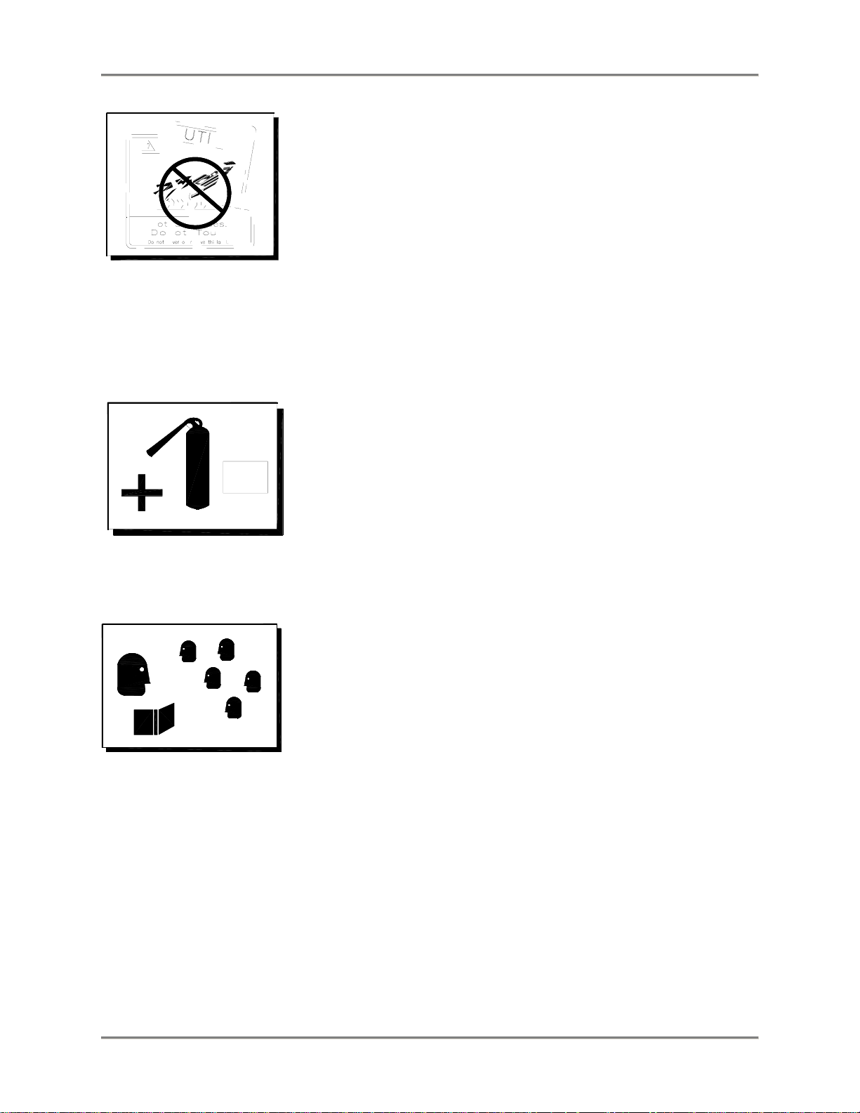
Keep Safety Labels Clean and in Good Condition
Do not remove or cover any safety labels on your equipment. Keep
all safety labels clean and in good condition. Replace any damaged
or missing safety labels.
If you need new safety labels, contact:
BKI
Technical Services Department
P.O. Box 80400
Simpsonville, S.C. 29680-0400
Or call toll free: 1-800-927-6887
Outside the U.S., call 864-963-3471
Be Prepared for Emergencies
Be prepared for fires, injuries, or other emergencies.
911
Keep a first aid kit and a fire extinguisher near the equipment. You
must use a 40-pound Type BC fire extinguisher and keep it within 25
feet of your equipment.
Keep emergency numbers for doctors, ambulance services, hospitals,
and the fire department near your telephone.
Know your responsibilities as an Employer
• Make certain your employees know how to operate the equipment.
• Make certain your employees are aware of the safety precautions
on the equipment and in this manual.
• Make certain that you have thoroughly trained your employees
about operating the equipment safely.
• Make certain the equipment is in proper working condition. If you
make unauthorized modifications to the equipment, you will reduce
the function and safety of the equipment.
4
Page 7

Hot Food Deli Case Operation
Operation
Controls and Indicators
The deli case controls are shown in the figure below. The POWER switch turns the power supply to the
case on and off. The LIGHTS switch turns the lights in the case on and off. The POWER switch must be
turned on for the lights to operate.
10
10
9
8
7
6
THERMOSTAT
LOWER WELL
1
2
3
4
5
1
2
3
4
5
THERMOSTAT
UPPER CANOPY
9
8
7
6
LIGHTS
0FF ON
POWER
0FF ON
The well and canopy heaters for each well section of the case are individually controlled as shown in
figure above. (TSW cases – the well and shelf heaters are individually controlled .) With the in dicator on
the control knob turned to the 12 o’clock position as shown, the heaters p roduce no heat.
To increase the temperature of the lower well heater, rotate its control knob clockwise. Likewise, to
increase the temperature of the canopy heater, rotate its control knob counterclockwise.
Each well is equipped with a red pilot light indicator. The pilot light turns on to indicate that the heating
elements are active and turns off to indicate when elements reach a set temperature. During operation
the pilot light turns OFF and ON as the well maintains proper temperature.
Preheating
To preheat the equipment, position the temperature control knobs on each well to the number 5. You
should allow the equipment to preheat for a minimum of 30 minutes before loading it with product.
Check Federal and State Health and Sanitation Regulations for internal temperature required for holding
cooked foods for sale. Maintaining these temperatures often tend to allow continued cooking of certain
5
Page 8

Hot Food Deli Case Operation
products. Therefore, smaller amounts of bulk foods should be displayed at non-peak p eriods and the
warmer refilled as needed.
All meats and vegetables should be preheated to 160 degrees F. before being placed in the case.
A screen liner can be used in the bottom of the display pans that are used for holding meats. This will
keep meats from sticking to the bottom of the pans.
Temperature Adjustment
After placing the product into the equipment, it may be necessary to adjust the temperature adjustment
knobs in order to maintain the proper internal temperature for the product on display. A thermometer
should be used to read the internal temperature of each product. The temperature control knobs should
be set to the lowest possible number that will maintain the proper product temperature.
Operational Guidelines
Keep portable meat thermometers on hand. Check the food temperatures hourly.
Rotate the food products. Foods loaded in first should be served first as much as is practical.
Foods held for long periods of time are more difficult to maintain at proper temperature. Also, freshness
and product quality diminish if foods are held too long. Most areas of the country have sanitation
regulations governing how long foods can be held. Make certain to check with your local auth orities.
Unit Shutdown
Remove all food pans holding the food product from the equipment. Turn OFF the power to the wells by
positioning the temperature knobs to the OFF position. Turn OFF the lights. After the temperature has
cooled down, remove any residue from the wells and clean the equipment thoroughly.
6
Page 9

Hot Food Deli Case Installation
R
Installation
Unpacking and Handling
YOU are responsible for filling all freight claims with the delivering truck line. Inspect all cartons and
crates for damage as soon as they arrive. If damage to cartons or crates is found, or if a shortage is
found, note this on the bill of lading (all copies) prior to signing.
If damage is found when the equipment is opened, immediately call the delivering truck line and follow up
the call with a written report indicating concealed damage to your shipment. Ask for an immediate
inspection of your concealed damage item. Packaging material MUST be retained to show the inspector
from the truck line.
Do not walk on top of deli cases or damage to the cases and serious personal
injury could occur. The cases are not structurally designed to support excessive
external loading such as the weight of a person. Do not place heavy objects on
the deli cases.
Move the deli case as close as possible to its permanent location before moving the case off of the
shipping pallet. Make certain there are no separately packed accessories b efore discarding packaging.
During shipment, the lubricant in the gas springs may have settled. This can cause the glass not to
remain open in the raised position. To avoid this, fully raise and lower the glass manually 4 or 5 times.
Floor Model
Leveling
Deli cases must be installed level to insure proper operation and alignment to adjoining equipment. Use a
carpenter’s level as shown in Figure 1. Begin lineup leveling from the highest point of the store floor.
LEVEL
CASE
COUNTE
TOP END
FLANGE
BLACK SHEET
METAL SCREWS
BOLT BASES OF ADJOINING
CASES TOGETHER AT
THESE (4) LOCATIONS
LEG
LEVELER
RAISE
LOWER
BLACK KICK
PLATES
(FRONT & BACK)
Figure 1. Floor Model - Leveling & Kick Plate Mounting
7
Page 10

Hot Food Deli Case Installation
1. Level the case using the leg levelers at the corners of the case (Figure 1). 8 ft. cases have an
additional pair of leg levelers in the center – don’t forget to adjust these too.
2. Raise the low end of the case to level it, do not lower the high end.
3. Check for level side-to-side and front-to-back.
4. If you are installing adjoining cases, position the next case in line beside the level case and
proceed to the next step.
5. Level this case in the same manner.
6. When level, bolt the two cases together at the locations shown in Figure 1.
NOTE: None of the end components shown in Figure 2 should be attached to adjoining case
ends
If the cases have been properly leveled, the front panels and counter tops should align with a
small, uniform gap between the front panels of the two cases.
7. Proceed in the same manner until all the cases in the line are level and bolted together.
8. Complete the line up by slipping the Counter Top Joint Cover over the end flanges of the
adjoining counter tops.
Kick Plate Mounting
A black vinyl-covered kick plate is provided for the front and back of each case.
1. Slide the front kick plate (the wider of the two) behind the lower finished front panel of the case
(see Figure 1).
2. Make certain that the ends of the kick plate are flush with the ends of the lower finished front
panel and that the kick plate is flush to the floor.
3. Drill 5/32” diameter holes in the case base to match the pre-drilled holes in the kick plate.
4. Attach the kick plate to the case base with the black sheet metal screws provided.
5. Mount the back kick plate to the case in the same manner.
6. Place the End Kick Plates in position (see Figure 2).
NOTE: There are left and right hand parts. The longer end flange faces toward the front of the case
with the black side out. The End Kick Plates fit over the ends of the front and back kick plates and
flush to the floor.
8
Page 11

Hot Food Deli Case Installation
End Panel Mounting
1. Now, attach the End Trim Panels to the base ends. The studs on the Trim Panels pass throu gh
the mounting holes in the base ends (see Figure 2). Both End Trim Panels are the same.
2. If the panel does not align properly turn it end for end. The panels are secured from insid e with
the #10 Palnuts provided.
3. Attach the End Panels to the ends of the case(s) as shown in Figure 2 using the shoulder screws
provided. For Glass End Panels only, slide the plastic bushings provided over the shoulder
screws before inserting the screw into the glass panel. Be careful that the screws do not bind in
the holes in the glass panel.
NOTE: If the ends are already attached to the case, the End Kick Plates can be lowered to the
floor. To do this loosen the End Trim Panel nuts from inside the case then slide the Kick Plates
flush with the floor and tighten the Trim Panel nuts.
4. These cases are to be sealed to the floor if required by local health codes. Seal the kick plates to
the floor using a silicone-type sealant (Dow Corning RTV #732 or equivalent).
SHOULDER SCREWS
ATTACH GLASS END
PANEL TO THESE
THREADED INSERTS
END PANEL
END KICK PLATE
HELD CAPTIVE
BEHIND TRIM PANEL
TRIM PANEL STUDS
THRU THESE (4)
HOLES – ATTACH
FROM INSIDE BASE
w/#10-24 PALNUT
END TRIM PANEL
END KICK PLATE
Figure 2. Floor Model - End Kick Plate & End Panel Mounting
9
Page 12

Hot Food Deli Case Installation
(3)
Pedestal Model
Pedestal mounted cases are provided with a mounting frame that runs the full length of the case. This
allows the pedestals to be located at any point along the length of the case. Each case should be
supported by at least two pedestals. One pedestal can support the ends of two adjoining cases. If in
doubt, consult the factory for assistance in determining the proper pedestal loca tions for your particular
installation.
RETAINING CLIP CLAMPS
PEDEST AL FRAME TO BOTTOM
FLANGE OF CASE FRAME
(PAINTED or STAINLESS)
REAR COVER
INSTALL FIRST
LEVEL
CASE
FRONT COVER
(PAINTED or
MOUNTING RAILS ON
CASE FIT INSIDE
PEDESTAL ENDS
BOLT FRAMES OF AJOINING
CASES TOGETHER AT THESE
LOCATIONS
LEG
LEVELER
RAISE
PEDESTAL
FRAME
LOWER
STAINLESS)
FITS OVER REAR
COVER
Figure 3. Pedestal Model - Leveling and Cover Attachment
Leveling
Deli cases must be installed level to insure proper operation and alignment to adjoining equipment. Use a
carpenter’s level as shown in Figure 3. Begin lineup leveling from the highest point of the store floor.
1. Level the case using the leg levelers at the corners of the pedestals (see Figure 3).
2. Raise the low end of the case to level it, do not lower the high end.
3. Check for level side-to-side and front-to-back.
4. If you are installing adjoining cases, position the next case in line beside the level case and
proceed to the next step.
5. Level this case in the same manner.
6. When level, bolt the two cases together at the locations shown in Figure 3. If the cases have
been properly leveled, the front panels and counter tops should align with a small, uniform gap
between the front panels of the two cases.
10
Page 13

Hot Food Deli Case Installation
7. Proceed in the same manner until all the cases in the line are level and bolted together.
8. Complete the line up by slipping the Counter Top Joint Cover over the ends flanges of the
adjoining counter tops.
Front and Rear Cover Attachment
1. Slide the Rear Cover over the Pedestal Frame first (see Figure 3). Then slide the Front Cover
over the Frame with the sides of the Front Cover lapping over the side of the Rear Cover. The
Front Cover will extend approximately 4-1/2” from the front of the frame.
2. Drill two 5/32” diameter holes in each side of the Pedestal Frame to match the predrilled holes in
the covers.
3. Secure the covers to the frame using the #8 sheet metal screws provided.
4. These cases are to be sealed to the floor if required by local health codes. Seal the pedestal
covers to the floor using a silicone-type sealant (Dow Corning RTV #732 or equivalent).
End Panel Mounting
END
PANEL
¼” –20 NUTS ATTACH
LOWER SHOULDER
BOLTS FROM BACKSIDE
OF END PANEL
Figure 4. Pedestal Model - End Panel Mounting
1. Attach the End Panels to the ends of the case(s) as shown in Figure 4 using the shoulder screws
provided.
2. Attach the (2) lower shoulder screws to the End Panel with the ¼”-20 nuts provided. For Glass
End Panels only, slide the plastic bushings provided over the shoulder screws before inserting
the screw into the glass panel. Be careful that the screws do not bind in the holes in the glass
panel.
11
Page 14

Hot Food Deli Case Installation
Counter Model
Counter Mounted cases must be mounted on a level surface that can su pport the weight of the case and
it contents. Use a carpenter’s level as shown in Figure 3 to level the case.
These cases are to be sealed to the counter if required by local health codes. Seal the peri meter of the
case to the counter using a silicone-type sealant (Dow Corning RTV #732 or equivalent).
Attach the End Panels to the ends of the case as shown in Figure 4 using the shoulder screws provided.
The (2) lower shoulder screws shown in Figure 4 are not required on counter mounted cases.
For Glass End Panels only, slide the plastic bushings provided over the shoulder screws before inserting
the screw into the glass panel. Be careful that the screws do not bind in the holes in the glass panel.
Wiring
A wiring diagram for the specific model is shipped with the deli case. The wiring diagram provides
electrical specifications, an electrical schematic and a parts list. Refer to this wiring diagram and the deli
case serial number plate for electrical information.
Field wiring must be sized for the components amperes printed on the serial number plate. Actual ampere
draw may be less than specified.
All electrical connections should be in compliance with the NEC and all applicable local codes by a
licensed electrician. Refer to the wiring diagram furnished with your case for the electrical specifications.
The power supply connection is located on the bottom of the well compartment of the case (see Figure 5).
Two ¾ x 1 knockouts are provided for the required conduit connection. A second power supply
connection for the oven is provided on oven combo cases.
A wiring cutout is provided in the base bottom pan on floor model cases (see Figure 5). Refer to the case
specification sheet for the location of this cutout. Remove the cover over the wiring cutout and route the
wiring through the cutout. Cut a hole of the proper size and location in the cover for the conduit to pass
through and reinstall the cover.
Figure 5. Wiring Access
12
TERMINAL
ACCESS
COVER
(2) ¾” X 1”
KNOCKOUTS
WIRING CUTOUT
IN FLOOR MODEL
BASE
Page 15

Hot Food Deli Case Installation
Joining WDCTY Cases
1. After leveling the cases and bolting the bases together, bolt the canopies together.
2. Remove the screws from the back of the top inner covers (with lights) on each case and allow
them to swing forward.
3. Connect the canopies using the ¼”-20 X 3” bolt and nut provided (see Figure 6, View A-A).
Replace the top inside covers.
4. Mount the Platform, Counter Trim and Base Front Joint Covers by holding them in place and
marking the hole locations on the case.
5. Make certain the joint covers are centered on the joint and that they align vertically with each
other.
6. Drill the case holes 5/32” and attach joint covers with screws provided. Black screws are to be
used on the Platform Cover and the Base Front Cover if painted black.
Figure 6. Joining WDCTY Cases
13
Page 16

Hot Food Deli Case Maintenance
Maintenance
Failure to comply with the maintenance below could result in a serious accident.
Electrocution, equipment failure or property damage could result if an unlicensed
electrician performs electrical repair. Ensure that a licensed electrician perform
electrical repair.
Scheduled Maintenance
Use the following table to help manage scheduled maintenance activities.
Frequency Performed By Part Activity
Daily User Case Clean the entire Case. Refer to the
cleaning procedure below.
Cleaning
This unit should be cleaned at the end of each day. Use the following procedure:
Failure to remove power from this unit may cause severe electrical shock. This
unit may have more than one disconnect switch.
1. Turn the machine ‘off ‘ and allow it to cool down.
2. Remove any food pans.
Using abrasive cleaners may damage the cabinet finish. Use only a mild soap and
water solution.
Never steam clean or get excess water in the interior of the cabinet as this can
damage unit.
This appliance is not intended to be cleaned with a water jet.
3. Use a mild soap and water solution to clean parts.
4. Sponge the inside and outside with a mild soap and water solution.
5. Wipe the parts and cabinet dry with a soft, clean cloth.
14
Page 17

Hot Food Deli Case Maintenance
Troubleshooting
Refer to the table below for troubleshooting information.
Problem Cause Possible Solution
Electrical
Power switch is off. Reset the power switch.
No Heat
Defective Heating Element. Contact an authorized BKI service
Defective Thermostat. Contact an authorized BKI service
Loose Wire or bad
Holding Temperature Not
Adequate
No Power to the case. Check circuit breaker or fuses at
building power panel. If problem
persists, contact an authorized
BKI service agent for corrective
action.
Power switch if off. Reset the power switch.
agent for corrective action.
agent for corrective action.
Contact an authorized BKI service
Connection.
Case and food pans have
not been preheated.
One or more heating
elements or thermostats not
operating properly.
Product is below 160° F
when loaded.
agent for corrective action.
Refer to the preheating section on
page 5. If problem persists,
contact an authorized BKI service
agent for corrective action.
Contact an authorized BKI service
agent for corrective action.
Check product temperature
before loading the case.
Loose Wire or bad
Connection.
15
Contact an authorized BKI service
agent for corrective action.
Page 18

Hot Food Deli Case Notes
Notes
16
Page 19

Hot Food Deli Case Notes
17
Page 20

P.O. Box 80400, Simpsonville, S.C. 29680-0400, USA
http://www.bkideas.com
Made and printed in the U.S.A
LI0117/0804
 Loading...