

Page 1

High Capacity Rotisserie
Oven Series
SERIES: VGG
Operation Manual
Page 2

Rotisserie Oven Table of Contents
SS-OM-064.02 Revised 9/25/18
BKI LIMITED WARRANTY
2812 Grandview Dr. • Simpsonville, SC 29680 • USA
(864) 963-3471 • Toll Free: (800) 927-6887 • Fax: (864) 963-5316
WHAT IS COVERED This warranty covers defects in material and workmanship under normal use, and applies
only to the original purchaser providing that:
The equipment has not been accidentally or intentionally damaged, altered or misused;
The equipment is properly installed, adjusted, operated and maintained in accordance with
national and local codes, and in accordance with the installation and operating instructions
provided with this product.
The serial number rating plate affixed to the equipment has not been defaced or removed.
WHO IS COVERED This
warranty
is
extended
to the original
purchaser
and applies only to
equipment purchased
for use in the U.S.A.
COVERAGE PERIOD
Warranty claims must be received in writing by BKI within one (1) year from
date of installation or within one (1) year and three (3) months from data of
shipment from the factory, whichever comes first.
COB Models: One (1) Year limited parts and labor.
COM Models: Two (2) Year limited parts and labor. COM convection ovens also have a
two (2) year door warranty.
CO1 Models: Two (2) Year limited parts and labor. Five (5) Year limited door
warranty.
Warranty period begins the date of dealer invoice to customer or ninety (90) days
after shipment date from BKI, whichever comes first.
WARRANTY COVERAGE This
warranty
covers on-site labor, parts and
reasonable
travel
time
and travel
e
xpenses
of the
authorized
service
representative
up to (100) miles
round
trip and (2)
hours
travel time and
performed during regular, weekday business hours.
EXCEPTIONS Any exceptions must be pre-approved in advance and in writing by BKI. The extended
door warranty on convection ovens years 3 through 5 is a parts only warranty and does not
include labor, travel, mileage or any other charges.
EXCLUSIONS
Negligence
or acts of
God,
Thermostat calibrations
after (30) days
from equipment installation date,
Air and gas
adjustments,
Light
bulbs,
Glass doors and
door adjustments,
Fuses,
Adjustments
to
burner
flames and
cleaning of
pilot
burners,
Tightening
of screws or
fasteners,
Failures
caused
by erratic
voltages
or gas
suppliers,
Unauthorized
repair by
anyone other than
a BKI F
actory Authorized
Service Center,
Damage
in
shipment,
Alteration,
misuse or
improper installation,
Thermostats
and safety valves with
broken
capillary tubes,
Freight –
other than normal UPS charges,
Ordinary
wear and
tear,
Failure to follow
installation and/or operating instructions,
Events
beyond control
of the
company.
INSTALLATION Leveling, as well as
proper installation
and check out of all
new equipment -
per
appropriate installation
and use materials – is the responsibility of the
dealer
or
installer, not the
manufacturer.
REPLACEMENT PARTS
BKI genuine
Factory OEM parts receive a (90) day
materials warranty
effective from the
date of
installation
by a BKI F
actory Authorized
Service
Center.
Page 3

Rotisserie Oven Table of Contents
1
Table of Contents
Table of Contents .....................................................................................................................................................1
Introduction ...............................................................................................................................................................2
Safety Precautions .................................................................................................................................................2
Safety Signs and Messages ..............................................................................................................................2
Specific Precautions ..........................................................................................................................................3
Safe Work Practices ..........................................................................................................................................3
Safety Labels .....................................................................................................................................................5
Health and Sanitation Practices .............................................................................................................................5
Food Handling ....................................................................................................................................................5
Storage of Raw Meats .......................................................................................................................................5
Coding Cooked Foods .......................................................................................................................................5
Storage of Prepared Foods ................................................................................................................................5
Operation ...................................................................................................................................................................6
Controls and Indicators ..........................................................................................................................................6
Hardware Controls .............................................................................................................................................6
Configuring the CTS Oven Controller ....................................................................................................................7
Changing Access Code .....................................................................................................................................9
Importing Recipe & Configuration Files .............................................................................................................9
Exporting Recipe, Configuration and History Files ............................................................................................9
Exporting Recipe, Configuration and History Files (continued) ...................................................................... 10
Setting the Clock ............................................................................................................................................. 10
Viewing the Error and Event History File ........................................................................................................ 10
Cooking with the CTS Oven Controller ............................................................................................................... 11
Configuring the CTS Controller for use in the VGG Oven .................................................................................. 13
Controller Errors, Warnings and Events .............................................................................................................. 15
Errors .............................................................................................................................................................. 15
Warnings and Alarms ...................................................................................................................................... 15
Events ............................................................................................................................................................. 16
Accessory Use .................................................................................................................................................... 17
Trussing Chickens .......................................................................................................................................... 17
V-Spits ............................................................................................................................................................. 18
Standard Meat forks ........................................................................................................................................ 18
Baskets ........................................................................................................................................................... 18
Installation .............................................................................................................................................................. 19
Unpacking and Handling ..................................................................................................................................... 19
Location and Clearance ...................................................................................................................................... 19
Extraction ............................................................................................................................................................ 19
Wiring .................................................................................................................................................................. 19
General Guidelines ......................................................................................................................................... 19
Guidelines for European Appliances .............................................................................................................. 22
Operating ............................................................................................................................................................. 22
Safety Cut-Out ................................................................................................................................................ 22
Maintenance ........................................................................................................................................................... 23
Scheduled Maintenance ...................................................................................................................................... 23
Oven Cleaning (Daily) ..................................................................................................................................... 23
Troubleshooting ................................................................................................................................................... 26
Accessories ............................................................................................................................................................ 28
Wiring Diagrams .................................................................................................................................................... 29
NOTES .................................................................................................................................................................... 36
BKI Worldwide is a wholly owned subsidiary of Standex International Corporation.
Page 4

Rotisserie Oven Introduction
2
Introduction
Your BKI VGG is a computer controlled rotisserie oven. It utilizes a revolving mechanism and heating elements
that ensure even product cooking. A touchscreen control and switches are provided to allow for quick setup and
operation. Removable components allow for easy maintenance and cleaning.
The BKI name and trademark on this unit assures you of the finest in design and engineering -- that it has been
built with care and dedication -- using the best materials available. Attention to the operating instructions
regarding proper installation, operation, and maintenance will result in long lasting dependability to ensure the
highest profitable return on your investment.
PLEASE READ THIS ENTIRE MANUAL BEFORE OPERATING THE UNIT. If you have
any questions, please contact your BKI Distributor. If they are unable to answer your
questions, phone the applicable BKI Technical Services Department:
BKI
Technical Services Department
2812 Grandview Drive
Simpsonville, S.C. 29680
Or call toll free: 1-800-927-6887
Outside the U.S., call 864-963-3471
Safety Precautions
Always follow recommended safety precautions listed in this manual. Below is the safety alert symbol. When you
see this symbol on your equipment, be alert to the potential for personal injury or property damage.
Safety Signs and Messages
The following Safety signs and messages are placed in this manual to provide instructions and identify specific
areas where potential hazards exist and special precautions should be taken. Know and understand the meaning
of these instructions, signs, and messages. Damage to the equipment, death or serious injury to you or other
persons may result if these messages are not followed.
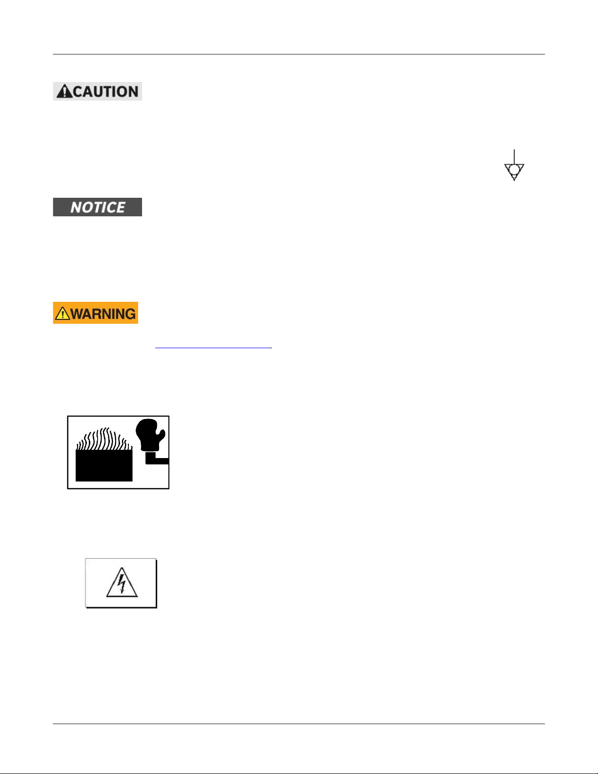
This message indicates an imminently hazardous situation which, if not avoided, will
result in death or serious injury.
This message indicates a potentially hazardous situation, which, if not avoided, could
result in death or serious injury.
This message indicates a potentially hazardous situation, which, if not avoided, may
result in minor or moderate injury. It may also be used to alert against unsafe practices.
This message is used when special information, instructions or identification are required
relating to procedures, equipment, tools, capacities and other special data.
Page 5
Rotisserie Oven Introduction
3
Specific Precautions
Equipotential Ground Plane
When a high current flows through a conductor, differences in potential appear between
the conductor and nearby metallic surfaces near the appliance. As a result, sparks may
be produced between the appliance and surrounding metal surfaces. These sparks
could cause serious injury, damage, or fire.
BKI provides an Equipotential ground terminal for the connection of a bonding
conductor after the installation of the appliance per lEC60417-1. This terminal
is located on the drive side of the oven base and is marked with this symbol.
Full Disconnection for IEC / CE Regulations
In accordance with Local and/or National wiring codes, the installer must provide a
means of full disconnection for overvoltage Category III conditions. An IEC approved
cord and plug combination will meet this requirement.
Units not provided with a cord and plug do not meet this requirement. In accordance with
Local and/or National wiring codes, the installer must provide the means of full
disconnection.
California Residents Only. This product can expose you to chemicals including
chromium, and lead which are known to the State of California to cause cancer and
birth defects or other reproductive harm. For more information go to
www.P65Warnings.ca.gov.
Safe Work Practices
Wear Safe Clothing Appropriate To Your Job
Always wear your insulated mitts when handling hot oven parts or touch any hot
metal surface. If you lose or damage your mitts, you can buy new ones at your local
restaurant equipment supply store or from your local BKI Distributor.
Always wear non-skid shoes when working around the oven or any other
equipment.
Never wear loose clothing such as neckties or scarves while operating this
equipment. Keep loose hair tied back or in a hair net while operating this equipment.
Always wear appropriate personal protection equipment during the cleaning process
to guard against possible injury.
WARNING – DANGEROUS VOLTAGE
This equipment uses high voltage. Serious injury can occur if you or any untrained
or unauthorized person installs, services, or repairs this equipment. Always Use an
Authorized Service agent to Service Your Equipment.
Page 6
Rotisserie Oven Introduction
4
Keep this manual with the Equipment
This manual is an important part of your equipment. Always keep it near for easy
access. If you need to replace this manual, phone the applicable BKI Technical
Services Department:
BKI
Technical Services Department
2812 Grandview Drive
Simpsonville, S.C. 29680
Or call toll free: 1-800-927-6887
Outside the U.S., call 864-963-3471
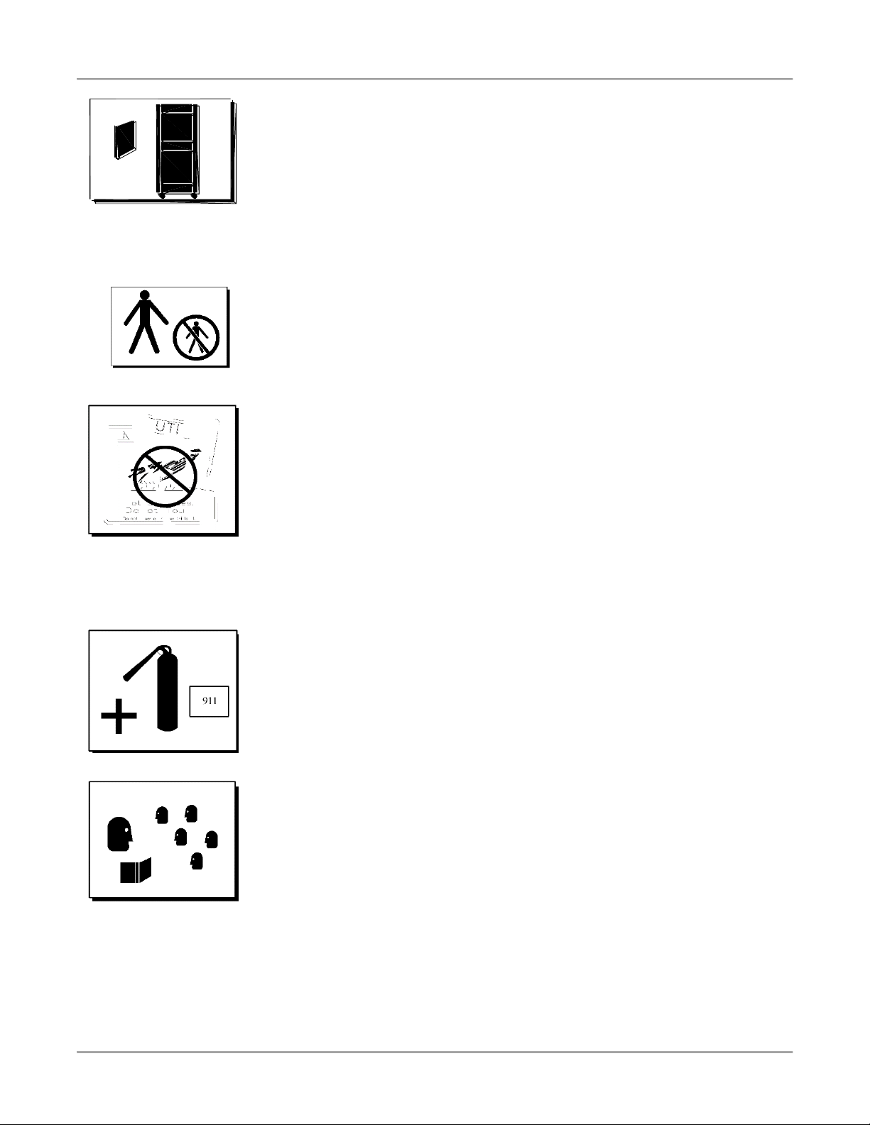
Protect Children
Keep children away from this equipment. Children may not understand that this
equipment is dangerous for them and others.
NEVER allow children to play near or operate your equipment.
Keep Safety Labels Clean and in Good Condition
Do not remove or cover any safety labels on your equipment. Keep all safety labels
clean and in good condition. Replace any damaged or missing safety labels. Refer
to the Safety Labels section for illustration and location of safety labels on this unit.
If you need a new safety label, obtain the number of the specific label illustrated on
page 5, then phone the applicable BKI Technical Services Department:
BKI
Technical Services Department
2812 Grandview Drive
Simpsonville, S.C. 29680
Or call toll free: 1-800-927-6887
Outside the U.S., call 864-963-3471
Be Prepared for Emergencies
Be prepared for fires, injuries, or other emergencies.
Keep a first aid kit and a fire extinguisher near the equipment. You must use a 40-
pound Type BC fire extinguisher and keep it within 25 feet of your equipment.
Keep emergency numbers for doctors, ambulance services, hospitals, and the fire
department near your telephone.
Know your responsibilities as an Employer
• Make certain your employees know how to operate the equipment.
• Make certain your employees are aware of the safety precautions on the
equipment and in this manual.
• Make certain that you have thoroughly trained your employees about operating
the equipment safely.
• Make certain the equipment is in proper working condition. If you make
unauthorized modifications to the equipment, you will reduce the function and
safety of the equipment.
Page 7
Rotisserie Oven Introduction
5
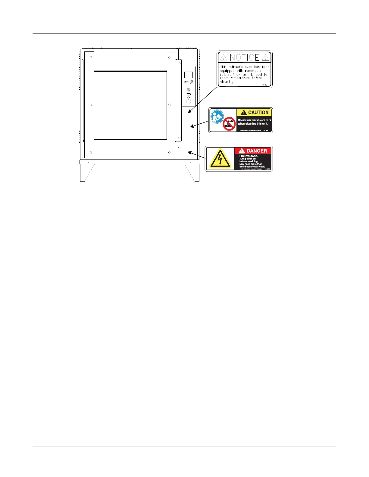
Safety Labels
Health and Sanitation Practices
BKI Rotisserie Ovens are manufactured to comply with health regulations and are tested and certified to NSF
standards. You must operate the equipment properly, using only quality products and use meat thermometers to
insure meats are thoroughly cooked.
Food Handling
• Wash hands thoroughly in warm, soapy water after handling raw poultry or meats.
• Clean and sanitize all utensils and surfaces that have been in contact with raw products. Clean and
sanitize the meat forks or baskets between cooking.
• Never place cooked meats on the same surfaces used to prepare raw meats, unless the area has been
thoroughly cleaned and sanitized.
Storage of Raw Meats
• Designate an area or shelf strictly for the storage of all raw meats to be used in the rotisserie.
• Raw product must always be stored at temperatures below 38° F. (3° C.).
• Never store or mix raw foods above cooked foods, as this is a health hazard. The drippings from raw
foods contaminate cooked or processed foods.
• All chicken and chicken parts to be stored overnight must be thoroughly iced down and refrigerated.
• Never put raw foods into the oven with cooked or partially cooked foods, as this is a health hazard. The
drippings from raw foods contaminate cooked foods.
Coding Cooked Foods
All products cooked during the day should be sold the same day.
NOTE: It is not the intent of the rotisserie program to have unsold merchandise at the end of the cooking day.
Follow your company’s procedures for the handling of any leftover product.
Storage of Prepared Foods
• Cold foods should be kept at or below 38° F. (3° C.).
• Hot foods must be maintained to meet local health codes, usually a minimum 145° F. (63° C.).
POWER
O I
Page 8
Rotisserie Oven Operation
6
Operation
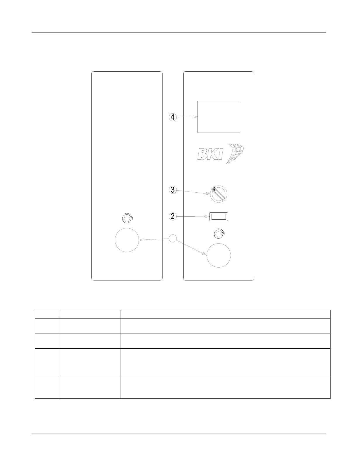
Controls and Indicators
Hardware Controls
Item #
Description
Function
1
Rotor Switch
Depressing the switch allows the operator to “jog” the rotor position when the
door is open. Releasing the switch stops the rotor.
2
Main Power Isolator
Light
This light illuminates to indicate that power is being applied to the oven from
the Main Power Isolator (Circuit Breaker).
3
Main Power Switch
Turns power to the entire unit on or off. When placed in the on position, the
Touchscreen controller is powered, lights illuminate and the rotor motor
engages (if both doors are closed). When placed in the off position, power is
removed from the entire unit.
4
Color Touchscreen
Controller
Used for operation and programming of the oven. A built-in beeper is used to
indicate touchscreen presses and other oven functions. It has 15
programmable cooking recipes.
POWER
O I
1
Page 9
Rotisserie Oven Operation
7
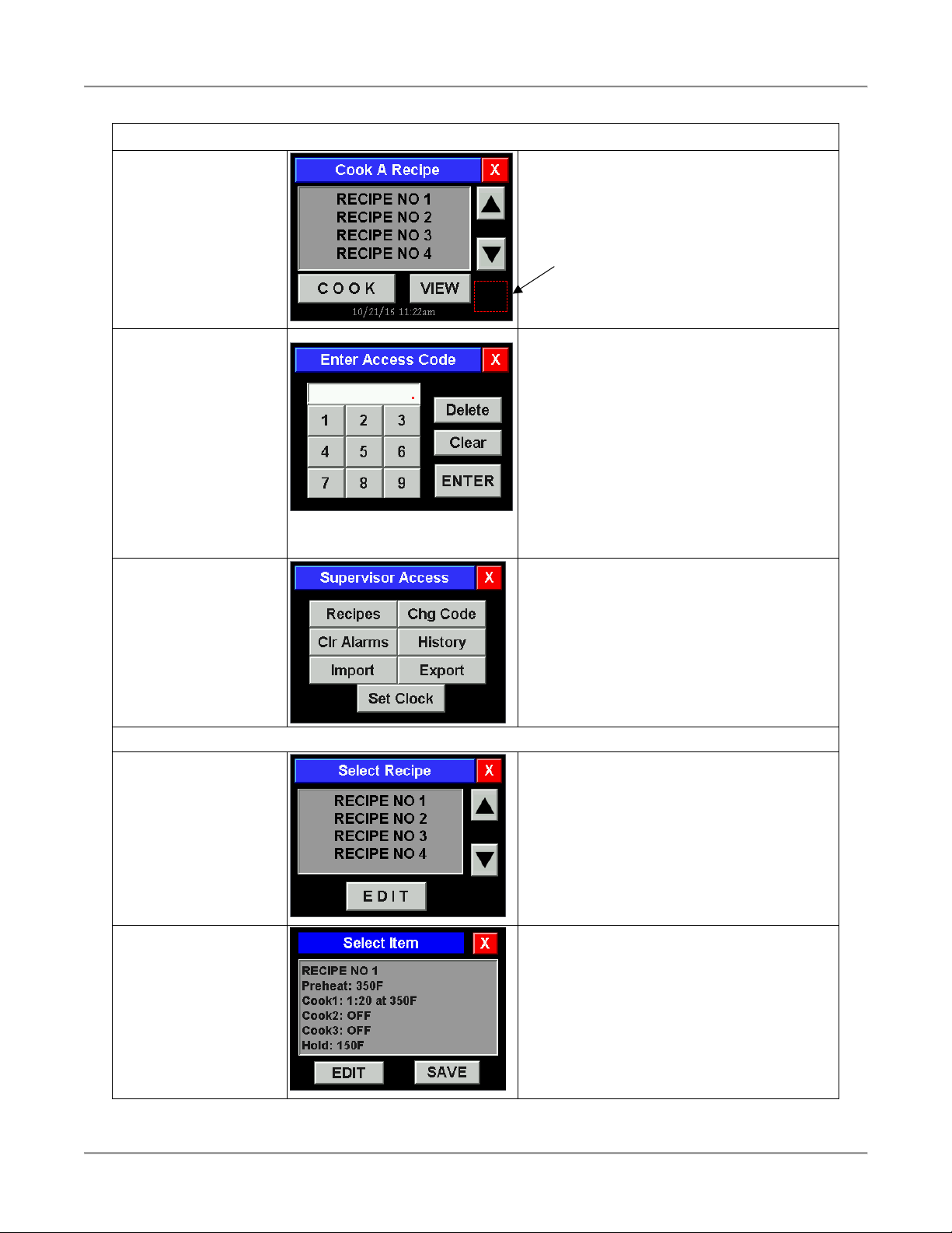
Configuring the CTS Oven Controller
Configuration Access
Touch and hold the
lower right portion of the
screen until the control
chirps twice.
The area on the control screen is black. The
red graphic in this diagrams indicates the
area to touch and hold.
Enter your access code.
Touch [X] to exit and
return to Main Recipe
screen.
[Delete] clears the last character.
[Clear] clears all characters.
The default Supervisor access code is 1234.
Use the default code the first time the
Configuration is accessed.
The access code can be changed after initial
access to configuration (recommended).
Write the new access code below and keep
this manual where only supervisors have
access to it.
Access Code ___________________
Use the screen keypad to enter the access
code then touch [ENTER].
Supervisor level
configuration screen is
displayed.
Touch [X] to exit and
return to Main Recipe
screen.
The supervisor has access to change
Recipes, change the Access Code, Set the
Clock, Import or Export recipes and
configurations or view the control History.
Touch the desired function button and follow
the configuration instructions below.
Recipe Editing
Touch and highlight the
desired recipe.
Touch [EDIT].
Touch [X] to exit and
return to Supervisor
Access screen.
There are 15 programmable recipes in the
control. Touch [▲] or [▼] to scroll through
the list.
Touch and highlight the recipe name in the
selection window. Touch [EDIT].
Touch and highlight the
desired Recipe Item.
Touch [EDIT].
Touch [X] to exit and
return to Select Recipe
screen.
Touch and highlight the Recipe Item to be
edited in the selection window. Touch
[EDIT].
Once all changes have been made you must
touch [SAVE] to store the recipe revisions.
X
Page 10
Rotisserie Oven Operation
8
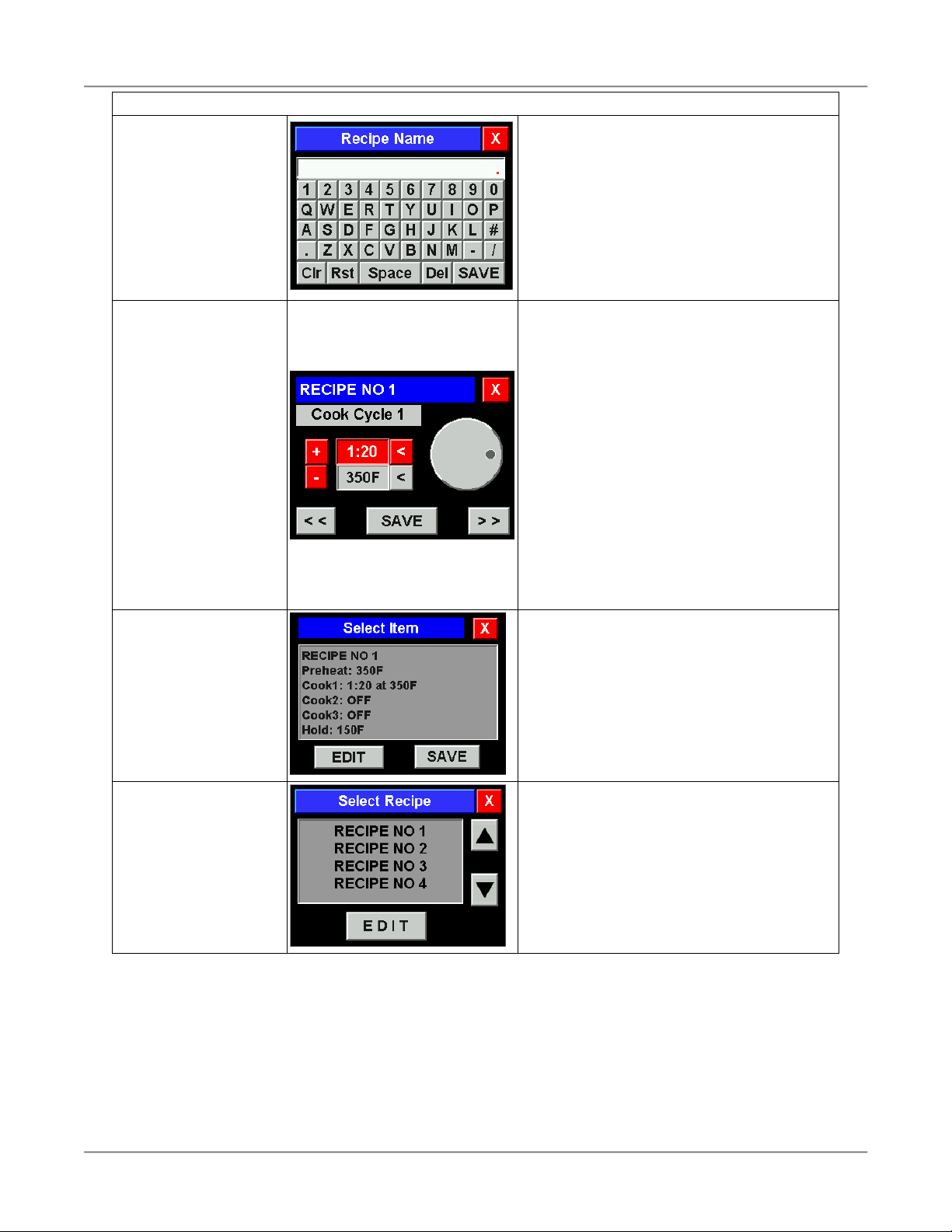
Recipe Editing (continued)
Edit Recipe Name.
Touch [SAVE].
Touch [X] to exit and
return to Select Item
screen.
Edit the Recipe Name using the alphanumeric keyboard. Recipe Names are limited
to a maximum of 14 characters.
Touch [SAVE] to save the new Recipe Name
and return to the Select Item screen.
[Clr] – Clears the editing box of all characters.
[Rst] – Restores the original recipe name.
[Space] – Adds a space character at the end.
[Del] – Deletes the last character.
Edit Recipe Items.
Touch [SAVE].
Touch [X] to exit and
return to Select Item
screen.
All Recipe Items (Preheat, Cook and Hold)
are edited in this screen. Touch [<<] and [>>]
to move between the Recipe Items.
The value field active for editing has a red
background. Touch the inactive field to make
it active for editing.
The Preheat and Hold items only have a
temperature value. The time field for these
items is greyed out and not selectable.
Use the dial on the right of the screen or the
[+] and [-] buttons to change the value.
To turn the Cook Cycle 2, Cook Cycle 3 or
Hold segments Off, set the temperature value
below 150F.
Touch [SAVE] to save the new values before
moving to the next Recipe Item.
Return to the Select
Item screen.
Touch [SAVE] to save
Recipe.
Touch [X] to exit and
return to Select Recipe
screen.
After Recipe editing is complete, touch [X] on
the Recipe Item screen above to return to the
Select Item screen.
You must touch [SAVE] to store the recipe
revisions.
Touch and highlight
another Recipe.
Touch [EDIT].
or
Touch [X] to exit and
return to Supervisor
Access screen.
Touch and highlight another Recipe name in
the selection window. Touch [EDIT].
or
Touch [X] to return to the Supervisor Access
screen if you are done editing Recipes.
Page 11
Rotisserie Oven Operation
9
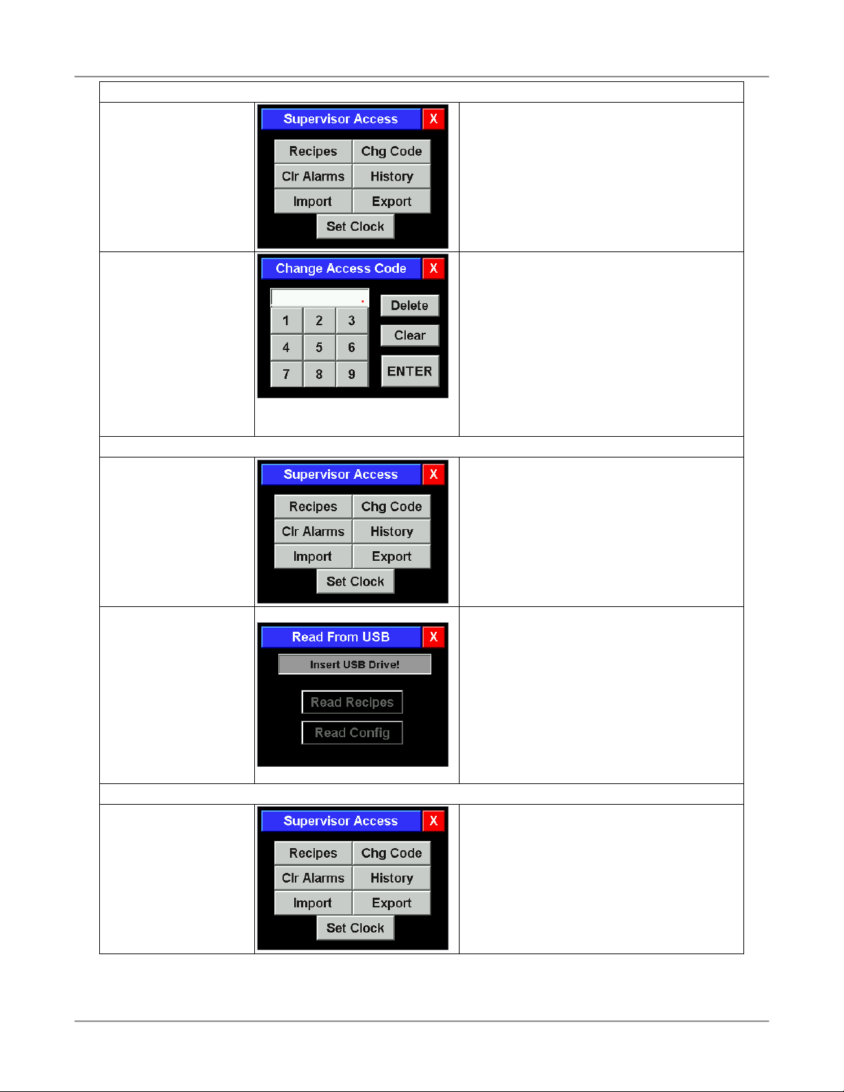
Changing Access Code
Supervisor level
configuration screen is
displayed.
Touch [X] to exit and
return to Main Recipe
screen.
Touch [Chg Code].
Enter new Access
Code.
Touch [ENTER].
Touch [X] to exit and
return to Supervisor
Access screen.
[Delete] clears the last character.
[Clear] clears all characters.
Use the screen keypad to enter the new
4 digit Access Code.
Touch [ENTER].
Record the new Access Code in the area
provided in the Configuration Access section
of this manual.
Once the new Access Code is entered the
old code will not provide configuration
access.
Importing Recipe & Configuration Files
Supervisor level
configuration screen is
displayed.
Touch [X] to exit and
return to Main Recipe
screen.
Supervisor Access gives the ability to Import
Recipe and Configuration files from a USB
flash drive.
Touch [Import].
Insert USB Drive.
Touch [Read Recipes]
and/or [Read Config].
Touch [X] to exit and
return to Supervisor
Access screen.
Insert the USB flash drive into the USB port
located on the control side of the oven. The
message line will change to read “Drive
Inserted” and the [Read Recipes] and
[Read Config] buttons will become active.
Touch [Read Recipes] and/or [Read Config]
to upload the files to the control.
Remove the USB drive when finished and the
control will return to the Supervisor Access
screen.
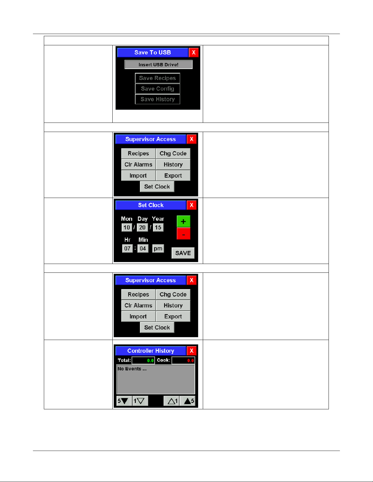
Exporting Recipe, Configuration and History Files
Supervisor level
configuration screen is
displayed.
Touch [X] to exit and
return to Main Recipe
screen.
Supervisor Access gives the ability to Export
Recipe, Configuration and History files to a
USB flash drive.
Touch [Export].
Page 12
Rotisserie Oven Operation
10
Exporting Recipe, Configuration and History Files (continued)
Supervisor level
configuration screen is
displayed.
Touch [X] to exit and
return to Main Recipe
screen.
Insert the USB flash drive into the USB port
located on the control side of the oven. The
message line will change to read “Drive
Inserted” and the [Save Recipes], [Save Config]
[Save History] buttons will become active.
Touch [Save Recipes], [Save Config] and/or
[Save History] to download the files to the USB
drive.
Remove the USB drive when finished and the
control will return to the Supervisor Access screen.
Setting the Clock
Supervisor level
configuration screen is
displayed.
Touch [X] to exit and
return to Main Recipe
screen.
The control has a real time clock that will
maintain the current date and time for up to
7 days with no power. This information is
used for the error and event history log.
Touch [Set Clock].
Touch value and
change using [+] and [-]
buttons.
Touch [SAVE] to save
and return to Supervisor
Access screen.
Touch and highlight the value below the item
to be changed. Use the [+] and [-] buttons to
change the item to the desired value.
To change the am/pm setting simply touch
that value to toggle between am and pm.
Touch [SAVE] to save the changes. The
control will return to the Supervisor Access
screen.
Viewing the Error and Event History File
Supervisor level
configuration screen is
displayed.
Touch [X] to exit and
return to Main Recipe
screen.
Supervisor Access gives the ability to view
the controls History log. The log includes the
total numbers of operating hours, the total
number of cooking hours and all event and
error messages.
Touch [History].
Controller History
screen is displayed.
Touch [SAVE] to save
and return to Supervisor
Access screen.
Total: the total number of hours the control
has been turned on.
Cook: the total number of hours the control
has been cooking (includes preheat).
Touch [▲] or [▼] to scroll through the list of
trackable events and errors. The date, time
and a descriptive string are displayed for
each event. A list of the errors and events
follows in this manual.
Page 13

Rotisserie Oven Operation
11
Cooking with the CTS Oven Controller
View a Recipe
Touch and highlight
desired recipe.
Touch [VIEW].
There are up to 15 recipes programed in the
control. Touch [▲] or [▼] to scroll through
the list.
Touch and highlight the recipe name in the
selection window. Touch [VIEW].
Touch [X] to return to
the Main Recipe screen.
The summary screen for the recipe selected
is displayed. The screen displays the
Preheat temperature setting, the Cook time
and temperature for each cook segment and
the Hold temperature.
Any stage labeled “off” is disabled in the
recipe.
Cooking a Recipe
Touch and highlight the
desired recipe.
Touch [COOK].
There are up to 15 recipes programed in the
control. Touch [▲] or [▼] to scroll through
the list.
Touch and highlight the recipe name in the
selection window. Touch [COOK].
Touch [PREHEAT] or
[COOK].
Touch [PREHEAT] to heat the oven to the
programmed preheat temperature.
Touch [COOK] to begin the first cook
segment without preheating the oven.
It is recommended to always preheat the
oven before starting to cook.
Touch [T] at any point to view the actual oven
cavity temperature. The temperature will be
displayed for 10 seconds.
Preheating screen is
displayed.
To exit the cook recipe
touch and hold [X] until
the control chirps twice.
The preheating screen for the recipe is
displayed.
The programed preheat temperature is
displayed at the bottom of the screen. Touch
[T] at any point to view the actual oven cavity
temperature. The oven cavity temperature
will be displayed for 10 seconds.
Page 14

Rotisserie Oven Operation
12
Cooking a Recipe (continued)
LOAD OVEN screen is
displayed.
To exit the cook recipe
touch and hold [X] until
the control chirps twice.
When the oven reaches the programed
preheat temperature the LOAD OVEN
screen is displayed.
The control will emit an audible alarm for 5
seconds and the screen background will
alternate between green and blue until the
oven is loaded or the large button is touched.
Load the oven.
Touch the large [START
COOK] button to begin
cooking.
After loading the oven (opening and closing
the door once) the START COOK screen is
displayed.
The screen background will alternate
between green and blue until the large button
is touched.
To beginning cooking, close the oven door
and touch the large [START COOK] button.
Main cooking screen is
displayed.
To exit the cook recipe
touch and hold [X] until
the control chirps twice.
The main cooking screen is displayed while
the cook in in progress.
The Time displayed is the time remaining in
the active cook segment. The progress bar
shows the progress through the sum of all of
the programed cook segment times.
The Temperature display is the programed
temperature for the active cook segment.
Touch [T] at any point to view the actual oven
cavity temperature. The oven cavity
temperature will be displayed for 10 seconds.
Touching [Ex] will add the preset extra time
(typically 5 minutes) to the active cook
segment.
End of Cooking
End of Cooking without Hold
On completion of the last cook
segment the [BEEP] button will
flash red and the control will
emit a continuous audible alarm.
To cancel the audible alarm,
touch [BEEP].
If additional cooking is required,
touch [Ex]. This will cook for the
preset extra time (typically 5
minutes) at the temperature
programed for the last cook
segment.
If no additional cooking is
required, remove all cooked
product from the oven then
touch and hold [X] until the
control chirps and returns to the
main recipe screen.
End of Cooking with Hold
On completion of the last cook segment the
[BEEP] button will flash red and the control will
emit a continuous audible alarm.
The control will automatically go into Hold and
maintain the oven cavity at the programed
temperature.
To cancel the audible alarm, touch [BEEP].
The control will stay in Hold.
Measure the internal temperature of the cooked
product.
If additional cooking is required, touch [Ex].
This will cook for the preset extra time (typically
5 minutes) at the temperature programed for
the last cook segment.
Once all cooked product has been removed
from the oven, touch and hold [X] until the
control chirps and returns to the main recipe
screen.
Page 15

Rotisserie Oven Operation
13
Configuring the CTS Controller for use in the VGG Oven
The Controller configuration must be verified as described below after installing a CP0065 Controller in the VGG
oven.
Touch and hold the
lower right portion of the
screen until the control
chirps twice.
The area on the control screen is black. The
red graphic in this diagrams indicates the
area to touch and hold.
Enter your access code.
Touch [X] to exit and
return to Main Recipe
screen.
[Delete] clears the last
character.
[Clear] clears all
characters.
The configuration access code is 9999.
Factory access screen
is displayed.
Touch [X] to exit and
return to Main Recipe
screen.
Touch the [Controller] button and follow the
configuration instructions below.
Touch [X] to exit and
return to Factory
Access screen.
Touch the T Ctrl: [Configure] button.
Touch [X] twice to
return to the Factory
Access screen.
Touch the Hysteresis: [+] and [-] buttons to
set the hysteresis to 5.
Touch [X] twice to return to the Factory
Access screen.
X
Page 16

Rotisserie Oven Operation
14
Alarm Configuration
screen is displayed.
Touch the [Alarms] button on the Factory
Access Screen.
Touch the [Heater] button at the bottom of
the Alarm Configuration screen.
Heater Alarm screen is
displayed.
Use the [+] and [-] buttons to set Time: to 3m
and Temp: to 50F.
Touch [X] twice to return to the Factory
Access screen.
Cooking Configuration
screen is displayed.
Touch the [Cooking] button on the Factory
Access Screen.
Use the [+] and [-] buttons to Extra: to 5.
Touch [X] three times to return to the main
Cook screen. The Controller is now properly
configured.
Page 17

Rotisserie Oven Operation
15
Controller Errors, Warnings and Events
Errors
These events cause the controller to halt operation and display the fault in
the System Error screen shown at right. The faults are not recoverable. The
System Error screen does allow the controller to be rebooted in an attempt
rectify the fault but this may not work.
An additional line of text will be displayed above “CALL FOR SERVICE” to
provide more detailed information about the type of error. In addition, an
error event will be recorded in the controller’s history.
Here is a list of errors with their descriptive text in the System Error and
History screens:
System Error text
History text
Error Description
TEMPERATURE PROBE ERROR
Probe Error
The temperature probe reading is out of range
indicating a probe failure.
TOUCHSCREEN ERROR
Tch Scr Error
The touch screen is cracked or contaminated.
ERROR SAVING TO MEMORY
STORAGE
NVM-W Error
AN error was detected writing to the
controller’s internal memory.
ERROR READING FROM
MEMORY STORAGE
NVM-R Error
AN error was detected reading from the
controller’s internal memory.
GP FAULT:nnnnnn AT
ADDR:aaaaaa
GP Fault
A general protection fault has occurred when
reading or writing to an invalid memory address.
Warnings and Alarms
The CTS Rotisserie Oven Controller has multiple alarms to warn the operator in
the case of certain problems within the oven. These alarms are informational
only and will not stop the controller from functioning. A warning message
formatted as shown at the right will flash on the screen every 30 seconds.
The alarms can be cleared using in [Clr Alarm] on the Supervisor Access screen. Refer to the Configuring the
CTS Oven Controller section of this manual. If the alarms conditions are still present after clearing the alarms, the
alarm will reappear.
Here is a list of the Warning messages and a description of the potential cause
OVEN NOT HEATING
CALL FOR SERVICE
If the oven does not begin to heat when Preheat is initiated this warning
message is displayed. At this point the gas spark ignition controller has
locked out. Turn the power to the oven off, then back on to reset the
gas spark ignition controller.
If the warning message is displayed again after the gas spark ignition
controller has been reset call the authorized BKI service agency to
service the oven.
CTRL TEMP WARNING
CHECK COOLING FAN
This warning message indicates the temperature in the oven’s control
compartment has risen to a temperature that would indicate a problem
with the cooling fan on the back of the control side of the oven. Verify
that the fan’s grill is not blocked and that the fan is operating when the
oven is on.
If the fan is not operating, call the authorized BKI service agency to
service the oven.
CTRL TEMP WARNING
CALL FOR SERVICE
This message is displayed when the temperature in the oven’s control
compartment rises to a temperature that will harm the oven’s components.
Use of the oven should be discontinued at the completion of the current
cooking recipe. Call the authorized BKI service agency to service the oven.
Page 18

Rotisserie Oven Operation
16
Events
Here is a list of controller system events which cause an entry in the History log:
Factory Rst
Factory Reset is performed as the controller is being tested at the factory. This
resets the recipes and controller configuration to defaults and performs a
touchscreen calibration.
Tch Scr Cal
Touch screen calibration during the factory reset or performed by the user.
Config Chg
This indicates that the controller configuration has been changed which includes
Supervisory or Factory level changes but not PID configuration changes.
PID Cfg Chg
The PID configuration was changed.
Access Err
An invalid password was entered.
Access Chg
The Supervisor password was changed.
Recipe Imp
The recipes were imported from a USB flash drive.
Recipe Exp
The recipes were exported to a USB flash drive.
Config Import
The controller configuration was imported from a USB flash drive.
Config Export
The controller configuration was exported to a USB flash drive.
USB Error
The controller was unable to create or find the proper file on the flash drive.
CJ Warning
The lower level cold junction time and temperature alarm was exceeded.
CJ Alarm
The higher level cold junction time and temperature alarm was exceeded.
IN2 Warning
The lower level IN2 probe time and temperature alarm was exceeded.
IN2 Alarm
The higher level IN2 probe time and temperature alarm was exceeded.
Heat Alarm
The oven temperature did not rise fast enough when the preheat was started.
Alarm Chg
The warning / alarming configuration was changed.
Page 19

Rotisserie Oven Operation
17
Accessory Use
Trussing Chickens
It is recommended that whole chickens be trussed before cooking. Trussing holds the wings and legs of the
chicken tightly against the body. This improves the visual appeal of the chickens while they are cooking. In
addition trussing keeps the chicken moist by retaining more of the natural juices and helps prevent the wing tips
from burning.
Using 6 ½” – 7” elastic ties, follow these simple steps to truss the chickens.
1. Fold wing tips back under the chicken.
2. With the back of the chicken up slip
the tie under the wings and pull back.
3. Pull and twist the tie over the back of the
chicken to form an “X”. Make sure wing
tips are under tie.
4. Turn the chicken over and pull the tie
over the ends of the legs.
Page 20

Rotisserie Oven Operation
18
V-Spits
Up to four (4) whole chickens can be placed on a VGG-8 V-spit and up to four (3) whole chickens can be placed
on a VGG-5 V-spit. Insert the tapered end of the V-spit under the legs and through the cavity of the trussed
chicken as shown below. Orient the spit with the “V” toward the breast side of the chicken. The legs and thighs of
the chicken should be on the same side of the V-spit as the breast.
Make sure the chickens are evenly spaced on the v-spit. Do not place more than the recommended number of
chickens on a V-spit. Chickens that are pushed tightly together on the V-spit will not brown properly during
cooking leaving “blonde” areas where the two chickens were touching.
The VGG-8 will hold up to 8 V-spits and the VGG-5 will hold up to 5 V-spits. When loading fewer V-spits, space
the V-spits as evenly as possible on the rotors. Balancing the load on the rotors will extend the life of the rotor
drive system. When loading only 2 or 3 spits DO NOT place them in adjacent mounting locations on the rotors.
Standard Meat forks
The standard meat forks are ideal for chicken and poultry. Use the following procedure to prepare the bird for
loading in the oven.
1. Fold wings to back, place on back with cavity away from you.
2. Run pointed ends of meat fork through sides of chicken under wings and through thighs (breast up and
legs down). Ensure that legs of adjacent birds DO NOT PRESS TIGHTLY TOGETHER, this will cause
the area of contact to be under-cooked!
3. Load the meat-forks by holding the meat-fork with the handle to the right–hand side, facing up.
4. Open the oven door.
5. Press Rotor Switch to rotate rotor to open position if required.
6. Place the pointed ends of the meat-fork into the left-hand disc holes.
7. From the control side, push the meat-fork into the disc to allow the right-hand (handle end) pins locate
into the right-hand disc.
8. Be sure to adjust the meat-fork position so that the handle end locates firmly in the spit groove.
Baskets
Baskets can be used for large chickens or other meats. After loading with product, simply locate pins in the holes
on the discs.
Page 21

Rotisserie Oven Installation
19
Installation
Serious injury, equipment damage or death could result if attempting to install this oven
yourself. Ensure that an authorized BKI service agent install the oven.
Unpacking and Handling
It is the owners’ responsibility to file all freight claims with the delivering truck line. Inspect all cartons and crates
for damage as soon as they arrive. If damage to cartons or crates is found, or if a shortage is found, note this on
the bill of lading (all copies) prior to signing.
If damage is found when the equipment is opened, immediately call the delivering truck line and follow up the call
with a written report indicating concealed damage to your shipment. Ask for an immediate inspection of your
concealed damage item. Packaging material MUST be retained to show the inspector from the truck line.
Remove all packing from the interior and exterior of the oven.
Location and Clearance
The oven must be mounted on a level surface capable of supporting the fully loaded oven. Refer to Chart 1 for
oven weight.
Adequate clearance must be provided around the oven for safety, proper operation and ventilation. Refer to
Chart 1 for required minimum clearances. Note that these are minimum clearances. If the oven is to be
permanently mounted near other immovable objects additional clearance must be provided for connection and
service of the oven on both sides.
All ventilation slots must be kept free from obstruction.
Extraction
Extraction is not a specific requirement for this type of appliance. Certain conditions, e.g./ installation in a confined
space, temperature controlled environment, continuous use or high volume production cooking may require the
need for extra ventilation or extraction. Consult your local ventilation/extraction air conditioning company or
contact the technical services department at BKI.
Wiring
Electrocution, equipment failure or property damage could result if an unlicensed
electrician performs the electrical installation. Ensure that a licensed electrician perform
the electrical installation in accordance with applicable local and national codes.
General Guidelines
• In the absence of local codes refer to the latest edition of one of the following:
• National Electrical Code, ANSI/NFPA 70-20XX (USA) which can be obtained from:
The National Fire Protection Association
Batterymarch Park
Quincy, MA 02269
• I.E.E. Wiring Regulations (Europe)
• Verify that the power supply conforms to the electrical rating listed on the oven data plate.
• Ensure that the appliance is grounded (earthed).
Page 22

Rotisserie Oven Installation
20
Power
Chart 1. Location and Clearance
Electrical Specifications (North America)
1Ph + Gnd, 60Hz
Volts Amps KW Breaker
208 29.3 6.1 40
220 23.5 5.2 30
240 27.8 6.7 40
Electrical Specifications (North America)
3Ph + Gnd, 60Hz
Volts Amps KW Breaker
208 17.2 6.1 25
220 13.8 5.2 20
240 16.3 6.7 25
Electrical Specifications (Europe)
230/400 Volts, 3Ph + Gnd + E, 50Hz
Amps Watts Breaker
L1 9.3 2182 10
L2 9.3 2130
L3 9.2 2120
Model
Height
Shipping
Weight
Minimum Clearance
Combustible Surface
Non-Combustible Surface
VGG-5
1009.5 mm
195 KG
152.5 mm
152.5 mm
39.7 in.
430 lb.
6 in.
6 in.
Page 23

Rotisserie Oven Installation
21
Power
Power
Electrical Specifications (North America)
3Ph + Gnd, 60Hz
Volts Amps KW Breaker
208 29.7* 10.6* 40*
220 26.4* 9.9* 35*
240 28.7* 11.8* 40*
* Ratings per oven cavity. VGG-16 requires a
separate power supply for each oven cavity.
Electrical Specifications (Europe)
230/400 Volts, 3Ph + Gnd + E, 50Hz
Model Amps KW Breaker
VGG-8 16.3 10.9 25
VGG-16 32.2 21.8 32
Model
Height
Shipping
Weight
Minimum Clearance
Combustible Surface
Non-Combustible Surface
A B C A B
C
VGG-8
1003.3 mm
259 KG
152.5 mm
152.5 mm
152.5 mm
51.0 mm
51.0 mm
51.0 mm
39.5 in.
570 lb.
6 in.
6 in.
6 in.
2 in.
2 in.
2 in.
VGG-16
2008.2 mm
453 KG
152.5 mm
152.5 mm
152.5 mm
51.0 mm
51.0 mm
51.0 mm
79 1/16 in.
1000 lb.
6 in.
6 in.
6 in.
2 in.
2 in.
2 in.
Page 24

Rotisserie Oven Installation
22
Guidelines for European Appliances
Note: - A method of disconnection from the main supply having a contact separation of least 3mm in all poles
must be incorporated in the fixed wiring.
• It is recommended that an R.C.D. with a 30ma trip and contact rating to suit the appliance current be
installed adjacent to the appliance.
• Type C/ 3 circuit breakers or appropriate rated fuses are recommended for installation at the supply end.
Note: - surge currents are present when this appliance is switched on from cold.
• Industrial plugs and sockets must comply with BS 4343/EN60309 (IEC309.2/CEE17).
Supply Cable Connection
• It is recommended that the power supply cable shall be an oil resistance sheathed flexible cable to BS
6007 (code designation HO7 RN-F).
• It is required that the power supply cable connection to the appliance terminal block, the earth conductor
is to be made at least 50mm longer than the length of the live (L) and neutral (N) conductors so that if the
supply cable is strained the earth conductor is the last to become disconnected.
• To gain access to the control panel and mains block connection, remove the 4-side panel securing
screws on the drive side of the oven.
• The mains block is sited toward the bottom right hand side of the control box. Cable entry is provided
through the base of the oven.
• Refer to the mains wiring diagram for correct connection.
Operating
Please read the operating instructions thoroughly and ensure all packaging has been removed before switching
main power ‘On’.
IMPORTANT: Ensure that whoever is operating this appliance is fully conversant with its working and is made
aware of the dangers of incorrect operation.
Safety Cut-Out
For added safety all VGG ovens have a built in thermal cut-out to protect against over-heating through component
failure or incorrect use. If for any reason the thermal cut-out operates, the oven will automatically shut down and
should be switched ‘Off’, disconnected from the mains and allowed to cool.
NOTE: - The thermal cut-out will not re-set automatically.
The oven must not be re-used until a qualified electrician or BKI service agent has checked it.
Page 25

Rotisserie Oven Maintenance
23
Maintenance
Failure to comply with the maintenance below could result in a serious accident or
equipment damage.
Failure to remove power from this unit before performing maintenance may cause
severe electrical shock. This unit may have more than one disconnect switch.
Scheduled Maintenance
Use the following table to help manage scheduled maintenance activities.
Frequency
Performed By
Part
Activity
Daily
User
Entire Oven
Perform oven-cleaning procedure.
6 months
User
Fan Blade
Remove and replace.
Oven Cleaning (Daily)
Cleaning is not only necessary for sanitary reasons, but will increase sales appeal and maximize operating
efficiency.
Failure to remove power from this unit may cause severe electrical shock. This unit may
have more than one disconnect switch.
Always wear appropriate personal protection equipment (googles, rubber glove &
long sleeved garments) when cleaning the oven to guard against possible injury.
Using abrasive cleaners will damage the cabinet finish. Use only a mild soap and
water solution or approved cleaner.
DO NOT USE OVEN CLEANER on this machine. Caustic cleaners will cause
damage to the machine.
NEVER USE A WATER HOSE OR A STEAM CLEANER TO WASH THIS UNIT.
Excess water can get into the interior of the cabinet and cause damage.
BKI Approved Cleaning Solutions
ECOLAB Greasestrip Plus
Proctor & Gamble DCT Oven Cleaner
J. Wilson Marketing Combi Brite Cleaner
1. Turn the Main Power Switch off and disconnect from the Main Power Isolator (Circuit Breaker).
2. Allow oven to cool below 50o C (120o F).
3. Empty the grease drawer using the drain valve or fat pump.
4. Remove all food products from the unit.
5. Remove V-spits, meat forks, hanging baskets and drip trays from the unit and place them in a large sink
to soak in hot cleaning solution. Clean the components with warm water, a sponge and BKI Cleaner.
Wipe dry with a clean cloth.
Page 26

Rotisserie Oven Maintenance
24
6. Remove the Rotor System as described below:
a. Lift the washer from the groove and slide down the shaft.
b. Slide each rotor cup down the shaft.
c. Remove the inner shaft.
NOTE: The welded bead in the center of shaft denotes the shaft removal direction.
d. Remove rotors.
7. Place the Rotor System components in a large sink to soak in hot cleaning solution. Clean the
components with warm water, a sponge and BKI Cleaner. Wipe dry with a clean cloth.
8. Remove the Fan Cover as described below:
a. Grasp the Fan Cover Hand Grip with both hands. Lift up on the Fan Cover then pull out
approximately 1/2” [12 mm].
b. Lower the front of the Fan Cover until the Switch Actuator clears slot in the top of the oven cavity (see
detail view).
c. Support the back of the Fan Cover with one hand and pull the Fan Cover out of the support pins in
the oven cavity sides with the other hand.
d. Remove the Fan Guard from the Circulation Bottom by pulling the Fan Guard handle out then up.
FAN COVER HAND GRIP
SWITCH
ACTUATOR
Pull Out
Lower Front of Cover
Pull Out
Lift Up
then
FAN GUARD
CIRCULATION
BOTTOM
Page 27

Rotisserie Oven Maintenance
25
9. Place the Fan Guard and Circulation Bottom in a large sink to soak in hot cleaning solution. Clean the
components with warm water, a sponge and BKI Cleaner. Wipe dry with a clean cloth.
10. Carefully clean the fan blades using a scrub brush and hot cleaning solution. Do not bend or disfigure the
fan blades.
11. Clean the top of oven. Carefully clean around fan and surrounding areas.
12. Replace the Fan Guard onto the Circulation Bottom. Then install this Fan Cover assembly back into the
oven cavity.
13. Clean grease drawer and tray area with hot soapy water.
14. Replace the grease drawer.
15. Clean the outside and inside of the rotisserie oven with warm water, a sponge and an approved cleaner
which is authorized for use on food surface areas.
16. Reassemble the rotor system in the oven.
Page 28

Rotisserie Oven Maintenance
26
Troubleshooting
Problem
Cause
Possible Solution
Unit will not turn on.
Main Power Isolator Light
is not lit.
Unit power plug disconnected
(where applicable).
Plug unit into mating receptacle.
Problem with building power
supply
Check circuit breaker at building power
panel. If problem persists, contact BKI
service agent for corrective action.
Unit will not turn on.
Main Power Isolator Light
is lit.
Blown Fuse
Contact BKI service agent for corrective
action.
Safety cut out thermostat
tripped or defective.
Contact BKI service agent for corrective
action.
Defective contactor.
Contact BKI service agent for corrective
action.
Rotor not rotating.
Door not completely closed.
Check that both doors are completely closed
Defective door switch.
Contact BKI service agent for corrective
action.
Blown Fuse
Contact BKI service agent for corrective
action.
Defective contactor.
Contact BKI service agent for corrective
action.
Defective motor or capacitor.
Contact BKI service agent for corrective
action.
Rotor will not rotate while
depressing Rotor switch
with door open but
operates with doors
closed.
Defective rotor switch.
Contact BKI service agent for corrective
action.
Oven does not heat at all.
Improper program settings.
Check program settings.
Improper parameter settings.
Contact BKI service agent for corrective
action.
Fan cover & circulation bottom
not installed or improperly
installed.
Check that components are properly
installed.
Fan cover switch defective.
Contact BKI service agent for corrective
action.
Defective controller or
contactor.
Contact BKI service agent for corrective
action.
Heating elements not
functioning.
Contact BKI service agent for corrective
action.
Oven heats up slowly
Improper line voltage.
Contact BKI service agent for corrective
action.
Page 29

Rotisserie Oven Maintenance
27
Problem
Cause
Possible Solution
Defective blower fan motor.
Contact BKI service agent for corrective
action.
Defective heating element.
Contact BKI service agent for corrective
action.
Control displays “999”
under the temperature
display.
Temperature probe connection
loose or defective probe.
Contact BKI service agent for corrective
action.
Cavity lights do not
illuminate when unit is on.
Faulty power supply.
Contact BKI service agent for corrective
action.
Individual cavity lamp
does not illuminate.
Defective lamp.
Contact BKI service agent for corrective
action.
Page 30

Rotisserie Oven Accessories
28
Accessories
Description
Part No.
Item
MEAT BASKET w/ 4 GOOSERS, VGG-8
(Not available for VGG-5)
MB0037
1
MEAT BASKET, VGG-5
MEAT BASKET, VGG-8
MB0040
MB0038
2
MEAT FORK, VGG-5
MEAT FORK, VGG-8
MF0044
MF0032
3
VEE SPIT, VGG-5
VEE SPIT, VGG-8
MF0045
MF0038
4
BKI RUBBER GLOVE
G0089
5
1 2 3
4 5
Page 31

Rotisserie Oven Wiring Diagrams
29
Wiring Diagrams
Refer to the table below to find the wiring diagram associated with your unit.
Wiring Diagram
Part #
Figure #
VGG-8 10.2kW, 208V-240V, 3 Phase Delta
SB55090000
Figure 11
VGG-8 12.0kW, 208V-240V, 3 Phase Delta
SB55090100
Figure 12
VGG-8 10.2kW, 230/400V, 3 Phase Wye
SB55090200
Figure 13
VGG-8 12.0kW, 230/400V, 3 Phase Wye
SB55090300
Figure 14
VGG-5 208-240V, 3 Phase Delta
SB55092000
Figure 15
VGG-5 230/400V, 3 Phase Wye
SB55092100
Figure 16
Page 32

Rotisserie Oven Wiring Diagrams
30
TB2
SW1
L1
CN1
SW2
500 mA
F2
L1 L2 L3
3 Ph DELTA Wiring
Configuration
SW4
SW5
TC1
L1
COMPONENT PLATE
TB1
L3
L2
N
R1
R3
R2
TO M1 ROTOR MOTOR
(SEE CONNECTION
DIAGRAM)
DRIVE MOUNT
TB2
SW6
FN3
L3
H1
H2
H3
FN2 FN1
SW3
JOG
TC2
SENSOR
10
18
FN2
2A
2
10
23
19
FN1
17
3
SW6
1
14
1
M1
10
9
1
R3
R3
24
SW5
22
SW4
1
1
21
SW3
21
SW2
2
3
1
12
H2
13
H3
R2
11
H1
TC1
1
2
3 33
32
31
9
10
9
LADDER DIAGRAM
TB1
5
L1
R1
L1
L3
L2
N
SW1
4
L1
6
R1
TC2
24
M
WHITE
RED
BLUE
COMMON
208V
220-240V
M0101
FN1 & FN2 FAN MOTOR
CONNECTION
COMPONENT LEGEND
F1-F0394 FUSE, 8 A
F2-FU010UK FUSE, 1/2 A
FU004UK FUSE HOLDER
FN1\ M0101 FAN MOTOR, 208-240V
FN2/ FN0032 FAN IMPELLER
FN3\
FN4- FN0012 COOLING FAN, 230V
H1\C0321 CALROD, 3400W@208V
H2-C0322 CALROD, 3400W@230V
H3/
L1-LI016UK CLR PILOT LIGHT, 250V
L2-LED011 POWER SUPPLY, 12 Vdc
L3-EA55097100 LED LAMP
M1-AN5501500S GEARMOTOR, 208-240V
R1-R0150 CONTACTOR, 40A 4P
R2-R0127 CONTACTOR, 25A 4P
R0140 RC SUPPRESSOR
R3-R0171 RELAY, SPDT 220/240V
SW1\ S0304 2 POS. OPERATOR
/ S0307 CONTACT BLOCK, 1 N.O.
SW2\ S0309 PB OPERATOR
SW3/ S0307 CONTACT BLOCK, 1 N.O.
SW4- S0363 REED SWITCH, N.O.
SW5/
SW6- S0355 MICRO SWITCH
TB1-TB0125 #4, 4 P TERMINAL BLOCK
TB2-TB0003 #8, 3 POLE SECTION
TB0004 #8, 3 POLE END SECTION
TB0121 JUMPER, #8 x 2 POLE
TB0100 #10, 3 POLE SECTION
TB0102 #10, 3 POLE END PLATE
TB0106 JUMPER, #10 x 2 POLE
TB0109 TERMINAL END STOP
TC1-TM015UK THERMOSTAT, HI-LIMIT
TC2-CP0065 CONTROLLER, TOUCH
SCREEN
M
M1 DRIVE MOTOR
CONNECTION
CAPACITOR- 2.5 MFD, 440 VAC
RED
WHITE
BLACK
M0108
L1
L3
L2
N
27
F2
500 mA
Red (+)
Black (-)
or Blue
L2
+
-
Red
Blk
Red
Blk
Red
Blk
Red
Blk
9
+
-
+
-
+
-
L3
Red (+)
Black (-)
or Blue
L2
12 Vdc
120-
240
Vac
Red
Blk
Figure 11. VGG-8 10.2kW, 208V-240V, 3 Phase (SB55090000)
Page 33

Rotisserie Oven Wiring Diagrams
31
TB2
SW1
L1
CN1
SW2
500 mA
F1
L1 L2 L3
3 Ph DELTA Wiring
Configuration
SW4
SW5
TC1
L1
COMPONENT PLATE
TB1
L3
L2
N
R1
R3
R2
TO M1 ROTOR MOTOR
(SEE CONNECTION
DIAGRAM)
DRIVE MOUNT
TB2
SW6
FN3
L3
H1
H2
H3
FN2 FN1
SW3
JOG
TC2
SENSOR
10
18
FN2
2A
2
10
23
19
FN1
17
3
SW6
1
14
1
M1
10
9
1
R3
R3
24
SW5
22
SW4
1
1
21
SW3
21
SW2
2
3
1
12
H2
13
H3
R2
11
H1
TC1
1
2
3 33
32
31
9
10
9
LADDER DIAGRAM
TB1
5
L1
R1
L1
L3
L2
N
SW1
4
L1
6
R1
TC2
24
M
WHITE
RED
BLUE
COMMON
208V
220-240V
M0101
FN1 & FN2 FAN MOTOR
CONNECTION
COMPONENT LEGEND
F1-FU010UK FUSE, 1/2 A
FU004UK FUSE HOLDER
FN1\ M0101 FAN MOTOR, 208-240V
FN2/ FN0032 FAN IMPELLER
FN3\
FN4- FN0012 COOLING FAN, 230V
H1\C0323 CALROD, 4060W@208V
H2-C0326 CALROD, 3800W@230V
H3/
L1-LI016UK CLR PILOT LIGHT, 250V
L2-LED011 POWER SUPPLY, 12 Vdc
L3-EA55097100 LED LAMP
M1-AN5501500S GEARMOTOR, 208-240V
R1-R0150 CONTACTOR, 40A 4P
R2-R0127 CONTACTOR, 25A 4P
R0140 RC SUPPRESSOR
R3-R0171 RELAY, SPDT 220/240V
SW1\ S0304 2 POS. OPERATOR
/ S0307 CONTACT BLOCK, 1 N.O.
SW2\ S0309 PB OPERATOR
SW3/ S0307 CONTACT BLOCK, 1 N.O.
SW4- S0363 REED SWITCH, N.O.
SW5/
SW6- S0355 MICRO SWITCH
TB1-TB0125 #4, 4 P TERMINAL BLOCK
TB2-TB0003 #8, 3 POLE SECTION
TB0004 #8, 3 POLE END SECTION
TB0121 JUMPER, #8 x 2 POLE
TB0100 #10, 3 POLE SECTION
TB0102 #10, 3 POLE END PLATE
TB0106 JUMPER, #10 x 2 POLE
TB0109 TERMINAL END STOP
TC1-TM015UK THERMOSTAT, HI-LIMIT
TC2-CP0065 CONTROLLER, TOUCH
SCREEN
M
M1 DRIVE MOTOR
CONNECTION
CAPACITOR- 2.5 MFD, 440 VAC
RED
WHITE
BLACK
M0108
L1
L3
L2
N
27
F2
500 mA
Red (+)
Black (-)
or Blue
L2
+
-
Red
Blk
Red
Blk
Red
Blk
Red
Blk
9
+
-
+
-
+
-
L3
Red (+)
Black (-)
or Blue
L2
12 Vdc
120-
240
Vac
Red
Blk
Figure 12. VGG-8 12.0kW, 208V-240V, 3 Phase (SB55090100)
Page 34

Rotisserie Oven Wiring Diagrams
32
TB2
SW1
L1
CN1
SW2
500 mA
F2
L1 L2 L3 N
3 Ph WYE Wiring
Configuration
SW4
SW5
TC1
L1
COMPONENT PLATE
TB1
L3
L2
N
R1
R3
R2
TO M1 ROTOR MOTOR
(SEE CONNECTION
DIAGRAM)
DRIVE MOUNT
TB2
SW6
FN3
L3
H1
H2
H3
FN2 FN1
SW3
JOG
TC2
SENSOR
10
18
FN2
2A
2
10
23
19
FN1
17
3
SW6
1
14
1
M1
10
9
1
R3
R3
24
SW5
22
SW4
1
1
21
SW3
21
SW2
2
3
1
12
H2
13
H3
R2
11
H1
TC1
1
2
3 33
32
31
9
10
9
LADDER DIAGRAM
TB1
5
L1
R1
L1
L3
L2
N
SW1
4
L1
6
R1
TC2
24
M
WHITE
RED
BLUE
COMMON
208V
220-240V
M0101
FN1 & FN2 FAN MOTOR
CONNECTION
COMPONENT LEGEND
F1-F0394 FUSE, 8 A
F2-FU010UK FUSE, 1/2 A
FU004UK FUSE HOLDER
FN1\ M0101 FAN MOTOR, 208-240V
FN2/ FN0032 FAN IMPELLER
FN3\
FN4- FN0012 COOLING FAN, 230V
H1\
H2-C0322 CALROD, 3400W@230V
H3/
L1-LI016UK CLR PILOT LIGHT, 250V
L2-LED011 POWER SUPPLY, 12 Vdc
L3-EA55097100 LED LAMP
M1-AN5501500S GEARMOTOR, 208-240V
R1-R0150 CONTACTOR, 40A 4P
R2-R0127 CONTACTOR, 25A 4P
R0140 RC SUPPRESSOR
R3-R0171 RELAY, SPDT 220/240V
SW1\ S0304 2 POS. OPERATOR
/ S0307 CONTACT BLOCK, 1 N.O.
SW2\ S0309 PB OPERATOR
SW3/ S0307 CONTACT BLOCK, 1 N.O.
SW4- S0363 REED SWITCH, N.O.
SW5/
SW6- S0355 MICRO SWITCH
TB1-TB0125 #4, 4 P TERMINAL BLOCK
TB2-TB0003 #8, 3 POLE SECTION
TB0004 #8, 3 POLE END SECTION
TB0121 JUMPER, #8 x 2 POLE
TB0100 #10, 3 POLE SECTION
TB0102 #10, 3 POLE END PLATE
TB0106 JUMPER, #10 x 2 POLE
TB0109 TERMINAL END STOP
TC1-TM015UK THERMOSTAT, HI-LIMIT
TC2-CP0065 CONTROLLER, TOUCH
SCREEN
M
M1 DRIVE MOTOR
CONNECTION
CAPACITOR- 2.5 MFD, 440 VAC
RED
WHITE
BLACK
M0108
L1
L3
L2
N
27
F2
500 mA
Red (+)
Black (-)
or Blue
L2
+
-
Red
Blk
Red
Blk
Red
Blk
Red
Blk
9
+
-
+
-
+
-
L3
Red (+)
Black (-)
or Blue
L2
12 Vdc
120-
240
Vac
Red
Blk
Figure 13. VGG-8 10.2kW, 230/400, 50Hz, 3 Phase (SB55090200)
Page 35

Rotisserie Oven Wiring Diagrams
33
TB2
SW1
L1
CN1
SW2
500 mA
F2
L1 L2 L3 N
3 Ph WYE Wiring
Configuration
SW4
SW5
TC1
L1
COMPONENT PLATE
TB1
L3
L2
N
R1
R3
R2
TO M1 ROTOR MOTOR
(SEE CONNECTION
DIAGRAM)
DRIVE MOUNT
TB2
SW6
FN3
L3
H1
H2
H3
FN2 FN1
SW3
JOG
TC2
SENSOR
10
18
FN2
2A
2
10
23
19
FN1
17
3
SW6
1
14
1
M1
10
9
1
R3
R3
24
SW5
22
SW4
1
1
21
SW3
21
SW2
2
3
1
12
H2
13
H3
R2
11
H1
1
2
3 33
32
31
9
10
9
LADDER DIAGRAM
TB1
5
L1
R1
L1
L3
L2
N
SW1
4
L1
6
R1
TC2
24
M
WHITE
RED
BLUE
COMMON
208V
220-240V
M0101
FN1 & FN2 FAN MOTOR
CONNECTION
COMPONENT LEGEND
F1-F0394 FUSE, 8 A
F2-FU010UK FUSE, 1/2 A
FU004UK FUSE HOLDER
FN1\ M0101 FAN MOTOR, 208-240V
FN2/ FN0032 FAN IMPELLER
FN3\
FN4- FN0012 COOLING FAN, 230V
H1\
H2-C0326 CALROD, 3800W@230V
H3/
L1-LI016UK CLR PILOT LIGHT, 250V
L2-LED011 POWER SUPPLY, 12 Vdc
L3-EA55097100 LED LAMP
M1-AN5501500S GEARMOTOR, 208-240V
R1-R0150 CONTACTOR, 40A 4P
R2-R0127 CONTACTOR, 25A 4P
R0140 RC SUPPRESSOR
R3-R0171 RELAY, SPDT 220/240V
SW1\ S0304 2 POS. OPERATOR
/ S0307 CONTACT BLOCK, 1 N.O.
SW2\ S0309 PB OPERATOR
SW3/ S0307 CONTACT BLOCK, 1 N.O.
SW4- S0363 REED SWITCH, N.O.
SW5/
SW6- S0355 MICRO SWITCH
TB1-TB0125 #4, 4 P TERMINAL BLOCK
TB2-TB0003 #8, 3 POLE SECTION
TB0004 #8, 3 POLE END SECTION
TB0121 JUMPER, #8 x 2 POLE
TB0100 #10, 3 POLE SECTION
TB0102 #10, 3 POLE END PLATE
TB0106 JUMPER, #10 x 2 POLE
TB0109 TERMINAL END STOP
TC1-TM015UK THERMOSTAT, HI-LIMIT
TC2-CP0065 CONTROLLER, TOUCH
SCREEN
M
M1 DRIVE MOTOR
CONNECTION
CAPACITOR- 2.5 MFD, 440 VAC
RED
WHITE
BLACK
M0108
L1
L3
L2
N
27
F2
500 mA
Red (+)
Black (-)
or Blue
L2
+
-
Red
Blk
Red
Blk
Red
Blk
Red
Blk
9
+
-
+
-
+
-
L3
Red (+)
Black (-)
or Blue
L2
12 Vdc
120-
240
Vac
Red
Blk
Figure 14. VGG-8 12.0kW, 230/400, 50Hz, 3 Phase (SB55090300)
Page 36

Rotisserie Oven Wiring Diagrams
34
TB2
SW1
L1
CN1
SW2
500 mA
F2
L1 L2 L3
3 Ph Delta Wiring
Configuration
SW4
SW5
TC1
L1
COMPONENT PLATE
TB1
L3
L2
N
R1
R3
R2
TO M1 ROTOR MOTOR
(SEE CONNECTION
DIAGRAM)
DRIVE MOUNT
TB2
SW6
FN3
L3
H1
H2
H3
FN2 FN1
SW3
JOG
TC2
SENSOR
10
18
FN2
2A
2
10
23
19
FN1
17
3
SW6
1
14
1
M1
10
9
1
R3
R3
24
SW5
22
SW4
1
1
21
SW3
21
SW2
2
3
1
12
H2
13
H3
R2
11
H1
TC1
1
2
3 33
32
31
9
10
9
LADDER DIAGRAM
TB1
5
L1
R1
L1
L3
L2
N
SW1
4
L1
6
R1
TC2
24
M
WHITE
RED
BLUE
COMMON
208V
220-240V
M0101
FN1 & FN2 FAN MOTOR
CONNECTION
COMPONENT LEGEND
F1-F0394 FUSE, 8 A
F2-FU010UK FUSE, 1/2 A
FU004UK FUSE HOLDER
FN1\ M0101 FAN MOTOR, 208-240V
FN2/ FN0032 FAN IMPELLER
FN3\
FN4- FN0012 COOLING FAN, 230V
H1\ C0325 CALROD, 1900W@208V
H2-C0327 CALROD, 1900W@230V
H3/
L1-LI016UK CLR PILOT LIGHT, 250V
L2-LED011 POWER SUPPLY, 12 Vdc
L3-EA55097100 LED LAMP
M1-AN5501500S GEARMOTOR, 208-240V
R1-R0150 CONTACTOR, 40A 4P
R2-R0127 CONTACTOR, 25A 4P
R0140 RC SUPPRESSOR
R3-R0171 RELAY, SPDT 220/240V
SW1\ S0304 2 POS. OPERATOR
/ S0307 CONTACT BLOCK, 1 N.O.
SW2\ S0309 PB OPERATOR
SW3/ S0307 CONTACT BLOCK, 1 N.O.
SW4- S0363 REED SWITCH, N.O.
SW5/
SW6- S0355 MICRO SWITCH
TB1-TB0125 #4, 4 P TERMINAL BLOCK
TB2-TB0003 #8, 3 POLE SECTION
TB0004 #8, 3 POLE END SECTION
TB0121 JUMPER, #8 x 2 POLE
TB0100 #10, 3 POLE SECTION
TB0102 #10, 3 POLE END PLATE
TB0106 JUMPER, #10 x 2 POLE
TB0109 TERMINAL END STOP
TC1-TM015UK THERMOSTAT, HI-LIMIT
TC2-CP0065 CONTROLLER, TOUCH
SCREEN
M
M1 DRIVE MOTOR
CONNECTION
CAPACITOR- 2.5 MFD, 440 VAC
RED
WHITE
BLACK
M0108
L1
L3
L2
N
27
F2
500 mA
Red (+)
Black (-)
or Blue
L2
+
-
Red
Blk
Red
Blk
Red
Blk
Red
Blk
9
+
-
+
-
+
-
L3
Red (+)
Black (-)
or Blue
L2
12 Vdc
120-
240
Vac
Red
Blk
Figure 15. VGG-5, 208-240V, 3 Phase (SB55092000)
Page 37

Rotisserie Oven Wiring Diagrams
35
TB2
SW1
L1
CN1
SW2
500 mA
F2
L1 L2 L3 N
3 Ph WYE Wiring
Configuration
SW4
SW5
TC1
L1
COMPONENT PLATE
TB1
L3
L2
N
R1
R3
R2
TO M1 ROTOR MOTOR
(SEE CONNECTION
DIAGRAM)
DRIVE MOUNT
TB2
SW6
FN3
L3
H1
H2
H3
FN2 FN1
SW3
JOG
TC2
SENSOR
10
18
FN2
2A
2
10
23
19
FN1
17
3
SW6
1
14
1
M1
10
9
1
R3
R3
24
SW5
22
SW4
1
1
21
SW3
21
SW2
2
3
1
12
H2
13
H3
R2
11
H1
1
2
3 33
32
31
9
10
9
LADDER DIAGRAM
TB1
5
L1
R1
L1
L3
L2
N
SW1
4
L1
6
R1
TC2
24
M
WHITE
RED
BLUE
COMMON
208V
220-240V
M0101
FN1 & FN2 FAN MOTOR
CONNECTION
COMPONENT LEGEND
F1-F0394 FUSE, 8 A
F2-FU010UK FUSE, 1/2 A
FU004UK FUSE HOLDER
FN1\ M0101 FAN MOTOR, 208-240V
FN2/ FN0032 FAN IMPELLER
FN3\
FN4- FN0012 COOLING FAN, 230V
H1\
H2-C0327 CALROD, 1900W@230V
H3/
L1-LI016UK CLR PILOT LIGHT, 250V
L2-LED011 POWER SUPPLY, 12 Vdc
L3-EA55097100 LED LAMP
M1-AN5501500S GEARMOTOR, 208-240V
R1-R0150 CONTACTOR, 40A 4P
R2-R0127 CONTACTOR, 25A 4P
R0140 RC SUPPRESSOR
R3-R0171 RELAY, SPDT 220/240V
SW1\ S0304 2 POS. OPERATOR
/ S0307 CONTACT BLOCK, 1 N.O.
SW2\ S0309 PB OPERATOR
SW3/ S0307 CONTACT BLOCK, 1 N.O.
SW4- S0363 REED SWITCH, N.O.
SW5/
SW6- S0355 MICRO SWITCH
TB1-TB0125 #4, 4 P TERMINAL BLOCK
TB2-TB0003 #8, 3 POLE SECTION
TB0004 #8, 3 POLE END SECTION
TB0121 JUMPER, #8 x 2 POLE
TB0100 #10, 3 POLE SECTION
TB0102 #10, 3 POLE END PLATE
TB0106 JUMPER, #10 x 2 POLE
TB0109 TERMINAL END STOP
TC1-TM015UK THERMOSTAT, HI-LIMIT
TC2-CP0065 CONTROLLER, TOUCH
SCREEN
M
M1 DRIVE MOTOR
CONNECTION
CAPACITOR- 2.5 MFD, 440 VAC
RED
WHITE
BLACK
M0108
L1
L3
L2
N
27
F2
500 mA
Red (+)
Black (-)
or Blue
L2
+
-
Red
Blk
Red
Blk
Red
Blk
Red
Blk
9
+
-
+
-
+
-
L3
Red (+)
Black (-)
or Blue
L2
12 Vdc
120-
240
Vac
Red
Blk
Figure 16. VGG-5, 230/400V, 3 Phase (SB55092100)
Page 38

Rotisserie Oven NOTES
SS-OM-064.02 Revised 9/25/18
NOTES
2812 Grandview Drive, Simpsonville, S.C. 29680, USA
http://www.bkideas.com
Made and printed in the U.S.A
 Loading...