

Page 1
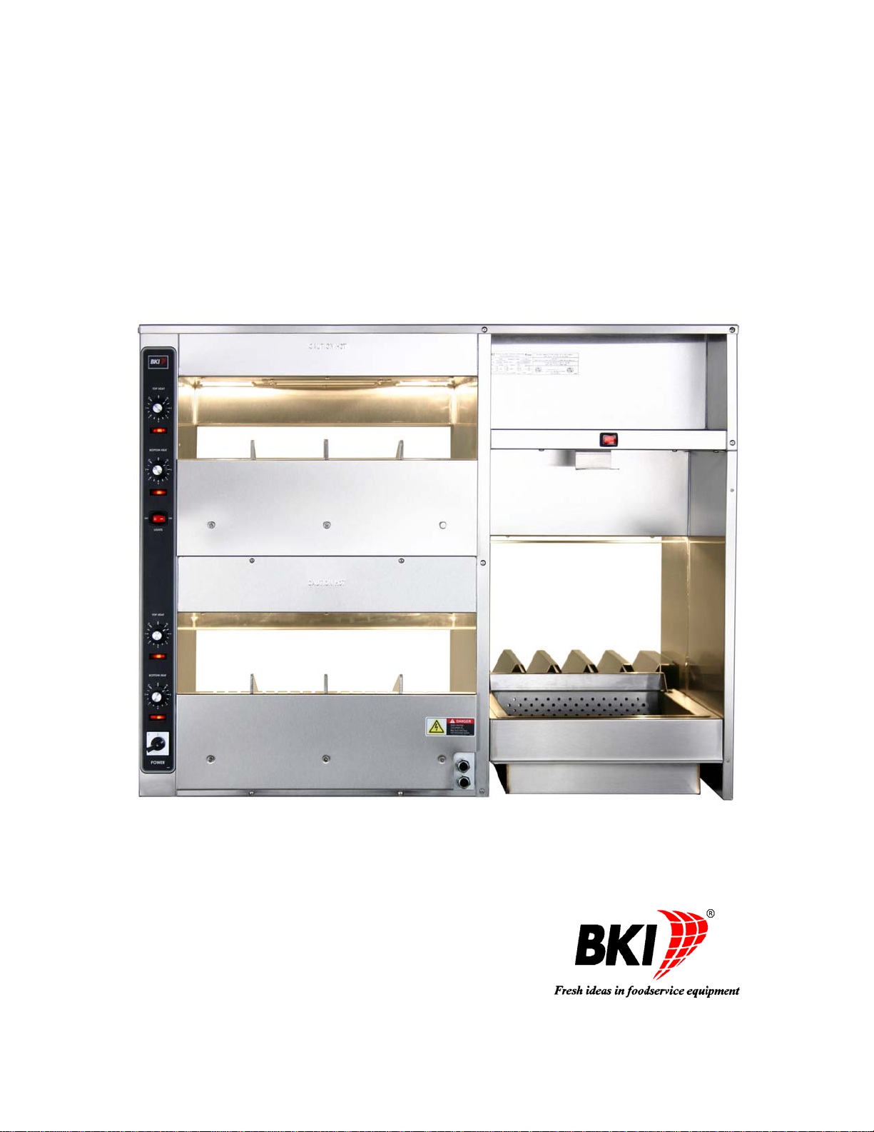
Sandwich/Fry Warmer
MODELS SFW, SFW-72, FW-15L
Service Manual
Serial Numbers 121866 and Higher
Page 2

Warranty Information
LIMITED ONE YEAR WARRANTY
BKI (The "Company") warrants to the original purchaser that at time of shipment from the
Company factory, this equipment will be free from defect in materials and workmanship. Written
notice of a claim under this warranty must be received by the Company within ONE YEAR from
the date of installation, but no longer than ONE YEAR AND THREE MONTHS from date of
shipment from the factory. Defective conditions caused by abnormal use or misuse, lack of or
improper maintenance, damage by third parties, alterations by unauthorized personnel, acts of
God, failure to follow installation and/or operating instructions, or any other events beyond the
reasonable control of the Company will NOT be covered under this warranty. The obligation of
the Company under this warranty shall be limited to repairing or replacing (at the option of the
Company) any part, with the exception of lamps, fuses, and glass (which are not covered under
warranty), which is found defective in the reasonable opinion of the Company. Any part found
defective by the Company will be repaired or replaced without charge F.O.B. factory,
Simpsonville, South Carolina or F.O.B. authorized BKI Distributor. The Company and/or its
authorized representatives will assume the normal replacement labor expense for the defective
part for the period of the warranty as stated above, excluding travel and/or other expenses
incidental to the replacement of the defective part, where replacement work is performed during
standard business hours and not subject to overtime, holiday rates, and/or any additional fees. IN
NO EVENT SHALL THE COMPANY BE LIABLE FOR LOSS OF USE, LOSS OF REVENUE OR
LOSS OF PRODUCT OR PROFIT OR FOR INDIRECT OR CONSEQUENTIAL DAMAGES
INCLUDING BUT NOT LIMITED TO, FOOD SPOILAGE OR PRODUCT LOSS. WARRANTY
DOES NOT COVER GLASS BREAKAGE. THE ABOVE WARRANTY IS EXCLUSIVE AND ALL
OTHER WARRANTIES, EXPRESS OR IMPLIED, ARE EXCLUDED INCLUDING THE IMPLIED
WARRANTIES OF MERCHANTABILITY AND FITNESS FOR A PARTICULAR PURPOSE.
REPLACEMENT PARTS
Any appliance replacement part, with the exception of lamps, fuses, and glass, which proves to
be defective in material or workmanship within ninety (90) days of installation will be replaced
without charge F.O.B. Factory, Simpsonville, SC or F.O.B. authorized BKI Distributor. The user
shall have the responsibility and expense of removing and returning the defective part to the
Company as well as the cost of reinstalling the replacement or repaired part.
Page 3

Sandwich/Fry Warmer Table of Contents
Table of Contents
Table of Contents .................................................................................................................................................... 1
Introduction.............................................................................................................................................................. 2
Safety Precautions................................................................................................................................................ 2
Safety Signs and Messages ............................................................................................................................. 2
Safe Work Practices ......................................................................................................................................... 3
Safety Labels .................................................................................................................................................... 5
Installation................................................................................................................................................................ 6
Instructions For Shipping Damage........................................................................................................................ 6
Electrical Information And Grounding ................................................................................................................... 6
Installation Instructions.......................................................................................................................................... 6
Right-Sided SFW.............................................................................................................................................. 6
Left-Sided SFW................................................................................................................................................. 7
Left-Sided SFW-72 ........................................................................................................................................... 8
FW-15L ............................................................................................................................................................. 9
Operation................................................................................................................................................................ 11
Controls and Indicators ....................................................................................................................................... 11
Unit Startup and Preheating................................................................................................................................ 12
SFW................................................................................................................................................................12
FW-15L ........................................................................................................................................................... 13
Sandwich Warmer Temperature Adjustment...................................................................................................... 13
Operational Guidelines........................................................................................................................................ 13
Unit Shutdown..................................................................................................................................................... 13
SFW................................................................................................................................................................ 13
FW-15L ........................................................................................................................................................... 13
Maintenance........................................................................................................................................................... 14
Scheduled Maintenance...................................................................................................................................... 14
SFW Cleaning................................................................................................................................................. 14
FW-15L Cleaning............................................................................................................................................ 14
Troubleshooting................................................................................................................................................... 15
Repair.................................................................................................................................................................. 16
Lamp Replacement......................................................................................................................................... 16
Replacement Parts ................................................................................................................................................ 17
Assemblies.......................................................................................................................................................... 17
SFW 120V Calrod Assembly .......................................................................................................................... 17
SFW Control Panel Assembly......................................................................................................................... 18
Components........................................................................................................................................................ 19
Wiring Diagrams.................................................................................................................................................... 21
Notes....................................................................................................................................................................... 25
1
Page 4
Sandwich/Fry Warmer Introduction
Introduction
Congratulations! You have chosen a Sandwich/Fry Warmer that will give you many years of fine service from the
original manufacturer, BKI.
The BKI name and trademark on this unit assures you of the finest in design and engineering — that it has been
built with care and dedication — using the best materials available. Attention to the operating instructions
regarding proper installation, operation, and maintenance will result in long lasting dependability to insure the
highest profitable return on your investment.
PLEASE READ THIS ENTIRE MANUAL BEFORE OPERATING THE UNIT. If you have
any questions, please contact your BKI Distributor. If they are unable to answer your
questions, contact the BKI Technical Service Department, toll free: 1-800-927-6887.
Outside the U.S., call 1-864-963-3471.
Safety Precautions
Always follow recommended safety precautions listed in this manual. Below is the safety alert symbol. When you
see this symbol on your equipment, be alert to the potential for personal injury or property damage.
Safety Signs and Messages
The following Safety signs and messages are placed in this manual to provide instructions and identify specific
areas where potential hazards exist and special precautions should be taken. Know and un derstand the meaning
of these instructions, signs, and messages. Damage to the equipment, death or serious injury to you or other
persons may result if these messages are not followed.
This message indicates an imminently hazardous situation that, if not avoided, will result
in death or serious injury.
This message indicates a potentially hazardous situation, which, if not avoided, could
result in death or serious injury.
This message indicates a potentially hazardous situation, which, if not avoided, may
result in minor or moderate injury. It may also be used to alert against unsafe practices.
This message is used when special information, instructions or identification are required
relating to procedures, equipment, tools, capacities and other special data.
2
Page 5
Sandwich/Fry Warmer Introduction
Safe Work Practices
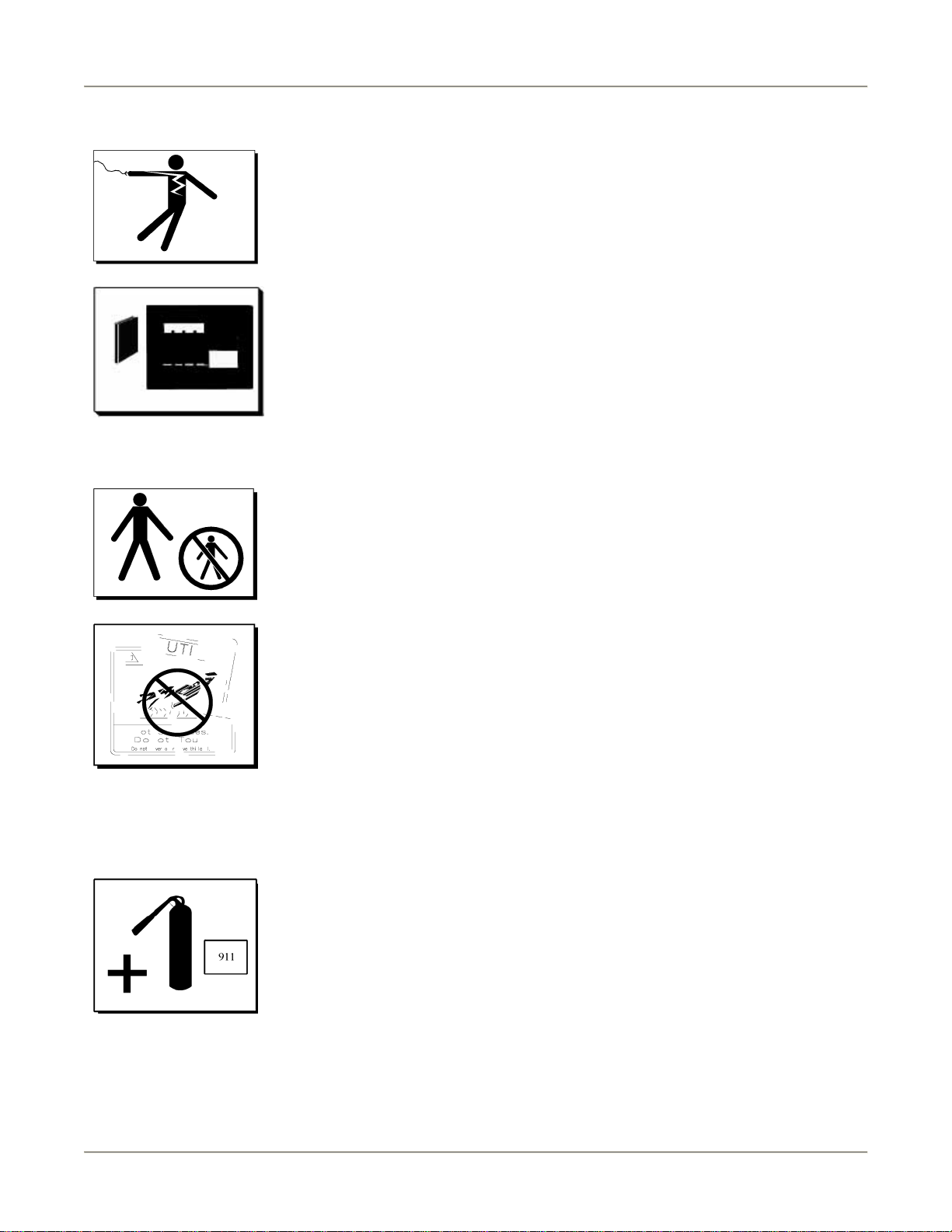
Beware of High Voltage
This equipment uses high voltage. Serious injury can occur if you or any untrained
or unauthorized person installs, services, or repairs this equipment. Always Use an
Authorized Service agent to Service Your Equipment.
Keep this manual with the Equipment
This manual is an important part of your equipment. Always keep it near for easy
access. If you need to replace this manual, contact:
BKI
Technical Services Department
P.O. Box 80400
Simpsonville, S.C. 29680-0400
Or call toll free: 1-800-927-6887
Outside the U.S., call 864-963-3471
Protect Children
Keep children away from this equipment. Children may not understand that this
equipment is dangerous for them and others.
NEVER allow children to play near or operate your equipment.
Keep Safety Labels Clean and in Good Condition
Do not remove or cover any safety labels on your equipment. Keep all safety labels
clean and in good condition. Replace any damaged or missing safety labels. Refer
to the Safety Labels section for illustration and location of safety labels on this unit.
If you need a new safety label, obtain the number of the specific label illustrated on
page 5, then contact:
BKI
Technical Services Department
P.O. Box 80400
Simpsonville, S.C. 29680-0400
Or call toll free: 1-800-927-6887
Outside the U.S., call 864-963-3471
Be Prepared for Emergencies
Be prepared for fires, injuries, or other emergencies.
Keep a first aid kit and a fire extinguisher near the equipment. You must use a 40-
pound Type BC fire extinguisher and keep it within 25 feet of your equipment.
Keep emergency numbers for doctors, ambulance services, hospitals, and the fire
department near your telephone.
3
Page 6

Sandwich/Fry Warmer Introduction
Know your responsibilities as an Employer
Make certain your employees know how to operate the equipment.
Make certain your employees are aware of the safety precautions on the
equipment and in this manual.
Make certain that you have thoroughly trained your employees about operating
the equipment safely.
Make certain the equipment is in proper working condition. If you make
unauthorized modifications to the equipment, you will reduce the function and
safety of the equipment.
4
Page 7
Sandwich/Fry Warmer Introduction
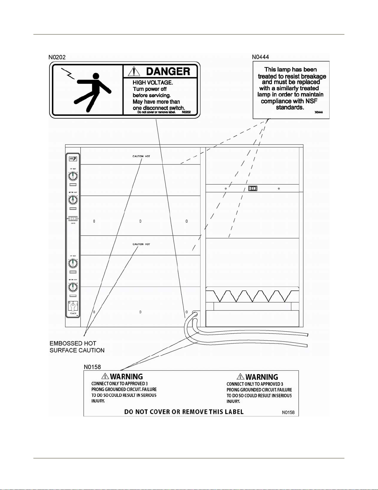
Safety Labels
5
Page 8
Sandwich/Fry Warmer Installation
Installation
Serious injury, equipment damage or death could result if attempting to install
this unit yourself. Ensure that an authorized BKI service agent installs the unit.
Instructions For Shipping Damage
You are responsible for filing all freight claims with the delivering truck line. Inspect all cartons and crates for
damage when they arrive. If there is damage noted to shipping crates or cartons, or, if a shortage is found, note
this on the bill of lading (all copies) before signing.
If damage is detected when the equipment is uncrated, immediately call the delivering truck line and follow up the
call with a written report indicating concealed damage to your equipment. Ask for an immediate inspection of your
concealed damage item. Crating material MUST be retained to show the inspector from the truck line.
Electrical Information And Grounding
Electrocution, equipment failure or property damage could result if an unlicensed
electrician performs the electrical installation. Ensure that a licensed electrician perform
the electrical installation in accordance with local codes, or in the absence of local codes,
with the National Electrical Code, ANSI NFPA 70-20XX.
This unit, when installed by an authorized BKI service agent, must be wired for use in accordance with all
applicable local, state, and federal codes. For specific electrical requirements and connections refer to the wiring
diagram attached to the unit or provided in the Service Manual.
Installation Instructions
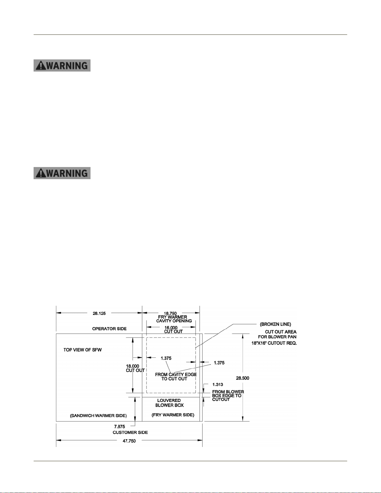
Right-Sided SFW
1. Obtain a suitable countertop location and place the entire unit in position.
2. Measure, mark and cut a hole in the countertop for the Fry Warmer blower pan to fit in according to the
following drawing.
6
Page 9
Sandwich/Fry Warmer Installation
3. Place the blower pan into the hole making sure that open side of the pan fits over the two tabs on the
louvered blower box.
4. Place the perforated pan insert into the blower pan.
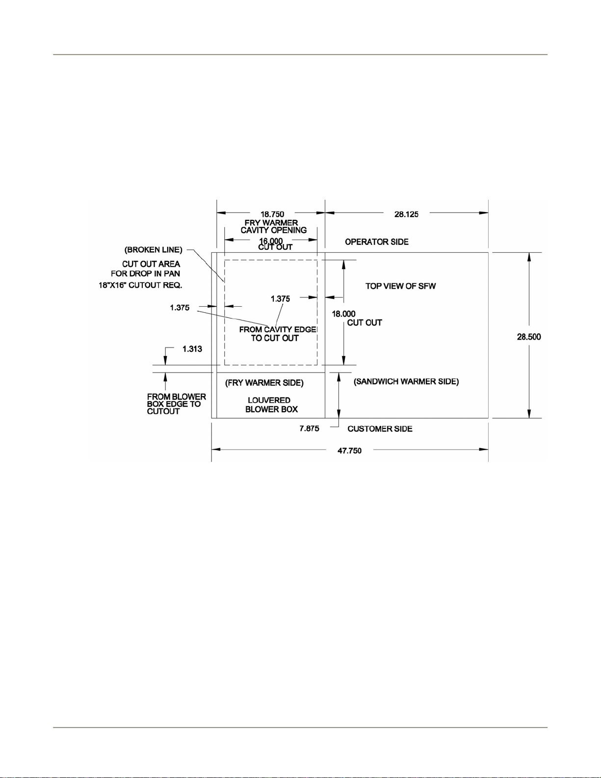
Left-Sided SFW
1. Obtain a suitable countertop location and place the entire unit in position.
2. Measure, mark and cut a hole in the countertop for the Fry Warmer blower pan to fit in according to the
following drawing.
3. Place the blower pan into the hole making sure that open side of the pan fits over the two tabs on the
louvered blower box.
4. Place the perforated pan insert into the blower pan.
7
Page 10

Sandwich/Fry Warmer Installation
Left-Sided SFW-72
1. Obtain a suitable countertop location and place the entire unit in position.
2. Measure, mark and cut a hole in the countertop for the Fry Warmer blower pan to fit in according to the
following drawing.
3. Place the blower pan into the hole making sure that open side of the pan fits over the two tabs on the
louvered blower box.
4. Place the perforated pan insert into the blower pan.
8
Page 11

Sandwich/Fry Warmer Installation
FW-15L
1. Obtain a suitable countertop location for the unit that will provide a clearance of 4” from the side louvers.
2. Cut a hole in the countertop to fit the collar weldment according to the drawing below.
3. Using a 2” hole saw, drill a hole in the countertop (under where the louvered blower box will be
positioned) for the power cord to pass through.
4. Position collar weldment into the cutout area with slotted holes toward the main unit.
5. Position the main unit as shown above ensuring that the side panel flanges are under the flange s of the
collar weldment.
6. Line up the back attachment holes on the flanges of the main unit with the slotted holes in the flanges of
the collar weldment.
7. Remove the louvered blower box to access the front attachment holes by unscrewing 7 screws shown
below.
9
Page 12

Sandwich/Fry Warmer Installation
8. Using a 1/8” drill bit, drill holes in countertop through existing holes in the main unit and collar weldment
flanges.
9. Secure main unit and collar weldment to countertop using #8 sheet metal screws.
10. Feed power cord (supplied), down through hole in countertop.
11. Reattach louvered blower box to main unit.
12. Seal main unit to the countertop to conform to NSF Standard 4, Item 4.28. (Dow Corning RTV #732 Multi
purpose Sealant.)
13. Place the blower pan into the hole making sure that open side of the pan fits over the two tabs on the
louvered blower box.
14. Place the perforated pan insert into the blower pan.
10
Page 13

Sandwich/Fry Warmer Operation
Operation
Controls and Indicators
11
Page 14

Sandwich/Fry Warmer Operation
Item # Description Function
1 Upper Sandwich Warmer
TOP HEAT temperature
control
2 Upper Sandwich Warmer
TOP HEAT pilot light
3 Upper Sandwich Warmer
BOTTOM HEAT
temperature control
4 Upper Sandwich Warmer
BOTTOM HEAT pilot light
5 LIGHTS ON/OFF Switch
for Upper and Lower
Sandwich Warmer
6 Lower Sandwich Warmer
TOP HEAT temperature
control
7 Lower Sandwich Warmer
TOP HEAT pilot light
8 Lower Sandwich Warmer
BOTTOM HEAT
temperature control
9 Lower Sandwich Warmer
BOTTOM HEAT pilot light
10 Sandwich Warmer POWER
ON/OFF Switch
11 Fry Warmer ON/OFF
Switch
Controls the temperature of the Upper Sandwich Warmer ceramic
heaters.
Cycles on and off to indicate when the Upper Sandwich Warmer
ceramic heaters turn on and off.
Controls the temperature of the Upper Sandwich Warmer heating
element.
Cycles on and off to indicate when the Upper Sandwich Warmer
heating element turns on and off.
Controls power to the Sandwich Warmer lights.
Controls the temperature of the Lower Sandwich Warmer ceramic
heaters.
Cycles on and off to indicate when the Lower Sandwich Warmer
ceramic heaters turn on and off.
Controls the temperature of the Lower Sandwich Warmer heating
element.
Cycles on and off to indicate when the Lower Sandwich Warmer
heating element turns on and off.
Controls power to the upper and lower Sandwich Warmers.
Controls power to the entire Fry Warmer.
Unit Startup and Preheating
SFW
1. Connect the plugs of the power cords into receptacles that match the power rating specified on the rating
tag.
2. Place the Fry Warmer ON/OFF switch to the ON (1) position. The switch should illuminate red, the bulb
should light and the chute and perforated pan should begin to heat up.
3. Place the Sandwich Warmer POWER ON/OFF switch to the ON (1) position.
4. Place the TOP HEAT and BOTTOM HEAT temperature control knobs on each sandwich wa rmer (upper
and lower) to the number 5 position. The pilot lights will cycle on and off to maintain proper sandwich
warmer temperature.
5. Place the Sandwich Warmer LIGHTS ON/OFF switch to the ON (1) position. The switch should illuminate
red.
6. Allow the equipment to preheat for 30 minutes before loading it with product.
12
Page 15

Sandwich/Fry Warmer Operation
FW-15L
1. Connect the plug of the power cord into a receptacle that matches the power rating specified on the rating
tag.
2. Place the Fry Warmer ON/OFF switch to the ON (1) position. The switch should illuminate red, the bulb
should light and the chute and perforated pan should begin to heat up.
3. Allow the equipment to preheat for 30 minutes before loading it with product.
Sandwich Warmer Temperature Adjustment
After loading the unit with product, it may be necessary to adjust the temperature control knobs in order to
maintain the proper internal temperature for the product on display. The temperature control knobs should be set
to the lowest possible number that will maintain the proper product temperature.
Operational Guidelines
Foods should be a minimum of 160 F. before being placed in the warmer.
Foods loaded in first should be served first as much as is practical.
Check Federal and State Health and Sanitation Regulations for internal temperature required for holding
cooked foods for sale. Maintaining these temperatures often tends to continue to cook certain products.
Therefore, smaller amounts of bulk foods should be displayed at non-peak periods and the warmer
refilled as needed.
This equipment is designed to hold foods for a short period of time only.
Unit Shutdown
SFW
1. Remove all food from the equipment.
2. Place the Fry Warmer ON/OFF switch to the OFF (0) position.
3. Place the Sandwich Warmer POWER ON/OFF switch to the OFF (0) position.
4. Allow the equipment to cool to room temperature.
5. Remove any residue and clean the equipment thoroughly.
FW-15L
1. Remove all food from the equipment.
2. Place the Fry Warmer ON/OFF switch to the OFF (0) position.
3. Allow the equipment to cool to room temperature.
4. Remove any residue and clean the equipment thoroughly.
13
Page 16

Sandwich/Fry Warmer Maintenance
Maintenance
Failure to comply with the maintenance below could result in a serious accident.
Electrocution, equipment failure or property damage could result if an unlicensed
electrician performs electrical repair. Ensure that a licensed electrician perform electrical
repair.
Scheduled Maintenance
This unit should be cleaned at the end of each working day. Use the following procedure:
Failure to remove power from this unit may cause severe electrical shock. This unit may
have more than one disconnect switch.
Never use abrasive cleaners that may damage the finish.
Never steam clean the interior.
Avoid getting excess water in the interior of the unit.
Do not clean the heater/blower assembly by applying compressed air.
Do not leave this unit on and unattended after business hours.
SFW Cleaning
1. Remove all food from the unit.
2. Place the Fry Warmer ON/OFF switch to the OFF (0) position.
3. Place the Sandwich Warmer POWER ON/OFF switch to the OFF (0) position.
4. Unplug both power cords.
5. Allow the equipment to cool to room temperature.
6. Remove and clean the Fry Warmer blower pan and pan insert.
7. Clean around the slotted holes at the air discharge on the blower box.
8. Clean the air intakes using a mild soap and water solution.
9. Sponge the inside and outside of the unit with a mild soap and water solution, being sure to clean all
areas. Avoid getting water in the interior of the unit.
10. Wipe the parts and unit dry with a soft, clean cloth and replace the blower pan and pan insert.
FW-15L Cleaning
1. Remove all food from the unit.
2. Place the Fry Warmer ON/OFF switch to the OFF (0) position.
3. Unplug the power cord.
14
Page 17

Sandwich/Fry Warmer Maintenance
4. Allow the equipment to cool to room temperature.
5. Remove and clean the Fry Warmer blower pan and pan insert.
6. Clean around the slotted holes at the air discharge on the blower box.
7. Clean the air intakes using a mild soap and water solution.
8. Sponge the inside and outside of the unit with a mild soap and water solution, being sure to clean all
areas. Avoid getting water in the interior of the unit.
9. Wipe the parts and unit dry with a soft, clean cloth and replace the blower pan and pan insert.
Troubleshooting
Problem Cause Possible Solution
Sandwich Warmer and/or
Fry Warmer will not turn on.
Product is not holding it’s
temperature
Fry Warmer
Warmer chute is not
heating and perforated pan
is not heating
Warmer chute is heating
and the perforated pan is
not heating
Power cords not
connected or circuit
breaker supplying power
to the unit has tripped.
Product temperature is
too low when loaded.
Or
Faulty component in
heating circuit
No power to unit. Make sure that the circuit breaker at the power
Fan has overheated and
cut off
Or
Heating coil has failed
Make sure power cords are connected and circuit
breaker is on. If problem persists contact a
licensed electrician.
Make sure product is above 160 F when loaded.
Contact an authorized BKI service agent for
corrective action.
supply is on and the Fry Warmer main power
switch is on. If problem persists, contact licensed
electrician.
Wipe the dust from the air intake louvers to allow
proper airflow and prevent fan overheating. Turn
the power switch off. Wait 60 seconds. Turn the
power switch back on.
Contact an authorized BKI service agent for
corrective action.
Noisy fan
Warmer chute is not
holding heat
Sandwich Warmer
Warmer is not heating
Fan blade is dirty or fan
bearings are failing
Ceramic heating
element failure
No power to unit
Or
Faulty component in top
or bottom heating circuit.
15
Contact an authorized BKI service agent for
corrective action.
Contact an authorized BKI service agent for
corrective action.
Make sure that the circuit breaker at the power
supply is on and the Sandwich Warmer main
power switch is on. If problem persists, contact
licensed electrician.
Contact an authorized BKI service agent for
corrective action.
Page 18

Sandwich/Fry Warmer Maintenance
Repair
Before replacing any parts, make sure the power has been turned off and the unit has
cooled down.
Lamp Replacement
Only use Teflon-coated lamp to prevent glass contamination.
1. Make sure power to the unit is OFF and the unit has cooled down.
2. Carefully remove the faulty lamp.
3. Replace with the new lamp.
16
Page 19

Sandwich/Fry Warmer Replacement Parts
Replacement Parts
Use the information in this section to identify replacement parts. To order replacement parts, call your local BKI
sales and service representative. Before calling, please note the serial number on the rating tag affixed to the unit.
Assemblies
SFW 120V Calrod Assembly
ITEM # PART # QTY DESCRIPTION
1 FC42110509
FC42101009
2 FB31212718 2 CALROD PAN SUPPT.BRKTS.SFW
3 C0110
C0066
4 FC42110609
FC42101109
5 I0005 2 INSULATION, 1"TK
1
1
1
1
1
1
CALROD MOUNT SM27 (SFW)
CALROD MOUNT SM27 (SFW-72)
CALROD, 120V 375W (SFW)
CALROD, 208V 800W (SFW-72)
INSUL COVER SM27 (SFW)
INSUL COVER SM27 (SFW-72)
17
Page 20

Sandwich/Fry Warmer Replacement Parts
SFW Control Panel Assembly
ITEM # PART # QTY DESCRIPTION
1 K0040 4 KNOB, S/S STRAT T0075
2 S0029
S0141
3 PL0005
PL0003
4
4
4
SWITCH, INFINITE 120V-1246 (SFW)
SWITCH, INFINITE 240V (SFW-72)
PILOT LIGHT, 125V (SFW)
PILOT LIGHT, 250V (SFW-72)
4 S0356 1 SWITCH, ROCKER 16A 250V
5 N0529 1 DECAL, CTL PNL SFW
6 S0006 1 SWITCH, 30A 2P ON/OFF
18
Page 21

Sandwich/Fry Warmer Replacement Parts
Components
PART # QTY DESCRIPTION PICTURE
B0066 6 2 BULB, 40A15 130V TEFLON COATED (SFW)
BULB, 40A15 130V TEFLON COATED (FW-15L)
B0553 8 BULB, 40W 230V TEFLON COATED (SFW-72)
C0060 4 CERAMIC HEATER 250W 120V FULL SIZE (SFW)
C0064 8 CERAMIC HEATER 250W 230V FULL SIZE (SFW-72)
C0080 2 2 CALROD, 120V 400W CERAMIC (SFW)
CALROD, 120V 400W CERAMIC (FW-15L)
C0057 2 CALROD, 230V 400W CERAMIC (SFW-72)
C0119 1 1 CALROD, 120V 1000W 140C C/U SWITCH (SFW)
CALROD, 120V 1000W 140C C/U SWITCH (FW-15L)
C0127 1 CALROD, 220V 1000W (SFW-72)
CS0024 2
CS0033 2 CORD SET, 20A 4’, 14/3 SJTO(SFW)
LH0021 6
LZ0025 1 1 V CUT BACK STOP, FRY SIDE (SFW)
M0093 1 1 MOTOR BLOWER ASSY 120V (SFW)
M0094 1 MOTOR BLOWER ASSY 208/240V (SFW-72)
CORD SET, 12/3 SJTO 8’ 30”LEAD (SFW)
1
CORD SET, 12/3 SJTO 8’ 30”LEAD (FW-15L)
LAMPHOLDER, #62602 HI TEMP (SFW)
2
LAMPHOLDER, #62602 HI TEMP (FW-15)
8
LAMPHOLDER, #62602 HI TEMP (SFW-72)
V CUT BACK STOP, FRY SIDE (FW-15)
MOTOR BLOWER ASSY 120V (FW-15L)
19
Page 22

Sandwich/Fry Warmer Replacement Parts
PART # QTY DESCRIPTION PICTURE
S0356 1 1 SWITCH, ROCKER 16A 250V (SFW/SFW-72)
SWITCH, ROCKER 16A 250V (FW-15L)
P0121 1
PAN INSERT 15" FW (SFW/SFW-72)
1
PAN INSERT 15" FW (FW-15L)
FB31209603 1 1 DIVIDER PAN, FRY SIDE (SFW/SWF-72)
DIVIDER PAN, FRY SIDE (FW-15L)
MB31213011 6
DIVIDER BAR (SFW)
14
DIVIDER BAR (SFW-72)
WB31207200 1 1 BLOWER PAN WELDMENT (SFW/SFW-72)
BLOWER PAN WELDMENT (FW-15L)
WN31210900 1 1 SIGN HOLDER, FRY SIDE (SFW/SFW-72)
SIGN HOLDER, FRY SIDE (FW-15L)
FB31211003 1 SIGN HOLDER SANDWICH SIDE (SFW)
WN31242100 1 SIGN HOLDER SANDWICH SIDE (SFW-72)
WB31219400 1 WELDMENT, C/TOP COLLAR W/LINER PAN (FW-15L)
20
Page 23

Sandwich/Fry Warmer Wiring Diagrams
Wiring Diagrams
Refer to the table below to find the wiring diagram associated with your unit.
Wiring Diagram Part # Figure # Page #
SFW SB31290600 Figure 1 22
SFW-72 SB31292000 Figure 2 23
FW-15L SB31291400 Figure 3 24
21
Page 24

Sandwich/Fry Warmer Wiring Diagrams
Figure 1. SFW
22
Page 25

Sandwich/Fry Warmer Wiring Diagrams
Figure 2. SFW-72
23
Page 26

Sandwich/Fry Warmer Wiring Diagrams
Figure 3. FW-15L
24
Page 27

Sandwich/Fry Warmer Notes
Notes
25
Page 28

P.O. Box 80400, Simpsonville, S.C. 29680-0400, USA
http://www.bkideas.com
Made and printed in the U.S.A
LI0272/0908
 Loading...