

Page 1

Powered Disposal Caddy
Series: PDC-14/PDC-14B
Service Manual
Page 2

BKI LIMITED WARRANTY
2812 Grandview Dr. • Simpsonville, SC 29680 • USA
(864) 963-3471 • Toll Free: (800) 927-6887 • Fax: (864) 963-5316
WHAT IS
WHO IS
COVERAGE PERIOD
WARRANTY COVERAGE
EXCEPTIONS
EXCLUSIONS
INSTALLATION
REPLACEMENT PARTS
COVERED
COVERED
This warranty covers defects in material and workmanship under normal use, and applies
only to the original purchaser providing that:
អ The equipment has not been accidentally or intentionally damaged, altered or misused;
អ The equipment is properly installed, adjusted, operated and maintained in accordance with
national and local codes, and in accordance with the installation and operating instructions
provided with this product.
អ The serial number rating plate affixed to the equipment has not been defaced or removed.
This
warranty
purchased
អ Warranty claims must be received in writing by BKI within one (1) year from
date of installation or within one (1) year and three (3) months from data of
shipment from the factory, whichever comes first.
អ COB Models: One (1) Year limited parts and labor.
អ COM Models: Two (2) Year limited parts and labor. COM convection ovens also have a
two (2) year door warranty.
អ CO1 Models: Two (2) Year limited parts and labor. Five (5) Year limited door
warranty.
អ Warranty period begins the date of dealer invoice to customer or ninety (90) days
after shipment date from BKI, whichever comes first.
This
warranty
e
xpenses
hours
travel time and
Any exceptions must be pre-approved in advance and in writing by BKI. The extended
door warranty on convection ovens years 3 through 5 is a parts only warranty and does not
include labor, travel, mileage or any other charges.
អ Negligence
អ Thermostat calibrations
អ Air and gas
អ Light
អ Glass doors and
អ Fuses,
អ Adjustments
អ Tightening
អ Failures
អ Unauthorized
អ Damage
អ Alteration,
អ Thermostats
អ Freight –
អ Ordinary
អ Failure to follow
អ Events
Leveling, as well as
appropriate installation
installer, not the
BKI genuine
date of
is
extended
for use in the U.S.A.
covers on-site labor, parts and
of the
authorized
or acts of
adjustments,
bulbs,
beyond control
installation
door adjustments,
to
burner
of screws or
caused
by erratic
repair by
in
shipment,
misuse or
and safety valves with
other than normal UPS charges,
wear and
installation and/or operating instructions,
proper installation
manufacturer.
Factory OEM parts receive a (90) day
by a BKI F
to the original
service
performed during regular, weekday business hours.
God,
after (30) days
flames and
fasteners,
voltages
anyone other than
improper installation,
tear,
of the
company.
and use materials – is the responsibility of the
actory Authorized
purchaser
reasonable
representative
from equipment installation date,
cleaning of
or gas
broken
and check out of all
and applies only to
travel
up to (100) miles
pilot
burners,
suppliers,
a BKI F
actory Authorized
capillary tubes,
new equipment -
materials warranty
Service
Center.
time
equipment
and travel
round
trip and (2)
Service Center,
per
dealer
or
effective from the
CS-TM-027.02 Revised 3/31/17
Page 3

Mobile Merchandiser Table of Contents
Table of Contents
Table of Contents ........................................................................................................................................ 1
Introduction ................................................................................................................................................. 2
Safety Precautions .................................................................................................................................... 2
Safety Signs and Messages ................................................................................................................. 2
Safe Work Practices ............................................................................................................................. 3
Operation ..................................................................................................................................................... 4
Safety Labels ........................................................................................................................................ 4
Controls ..................................................................................................................................................... 5
Hardware Controls................................................................................................................................ 5
Extracting Renderings from an Oven Drawer ........................................................................................... 6
Ovens Equipped with Extraction Drawer and Coupler Nipple .............................................................. 6
Ovens using the accessory Hand Wand .............................................................................................. 6
Discharge Fryer Oil into the Disposal Caddy ............................................................................................ 6
Discharging the Disposal Caddy Onboard Tank ...................................................................................... 7
Receptacles with a Coupler Nipple ...................................................................................................... 7
Ovens using the accessory Hand Wand .............................................................................................. 7
Operational Guidelines ............................................................................................................................. 7
Installation ................................................................................................................................................... 8
Instructions for Shipping Damage............................................................................................................. 8
Location and Placement ........................................................................................................................... 8
Electrical Information ................................................................................................................................ 8
Dimensions & Specifications .................................................................................................................... 9
Maintenance .............................................................................................................................................. 10
Scheduled Maintenance ......................................................................................................................... 10
Cleaning ............................................................................................................................................. 10
Troubleshooting ...................................................................................................................................... 11
Replacement Parts .................................................................................................................................... 12
General ................................................................................................................................................... 12
Pump with Bypass Valve ........................................................................................................................ 13
Tank Lid .................................................................................................................................................. 13
................................................................................................................................................................ 13
Accessories ............................................................................................................................................. 14
Wiring Diagram .......................................................................................................................................... 15
.............................................................................................................. Error! Bookmark not defined.
Notes .......................................................................................................................................................... 16
1
Page 4
Mobile Merchandiser Introduction
Introduction
Your BKI Powered Disposal Caddy safely extracts, transports and disposes of liquid cooking byproducts and frying oil. The caddy can be easily disassembled without the use of tools for maintenance
and cleaning.
The BKI name and trademark on this unit assures you of the finest in design and engineering — that it
has been built with care and dedication — using the best materials available. Attention to the operating
instructions regarding proper installation, operation, and maintenance will result in long lasting
dependability to insure the highest profitable return on your investment.
PLEASE READ THIS ENTIRE MANUAL BEFORE OPERATING THE UNIT. If
you have any questions, please contact your BKI Distributor. If they are unable to
answer your questions, phone the applicable BKI Technical Services
Department:
BKI
Technical Services Department
2812 Grandview Drive
Simpsonville, S.C. 29680
Or call toll free: 1-800-927-6887
Outside the U.S., call 864-963-3471
Safety Precautions
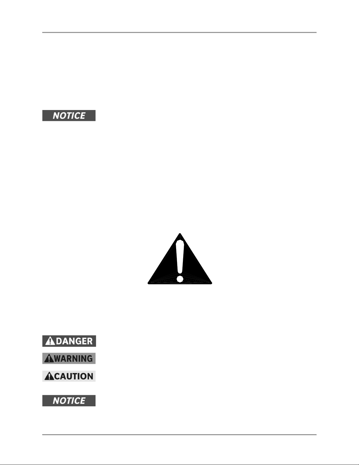
Always follow recommended safety precautions listed in this manual. Below is the safety alert symbol.
When you see this symbol on your equipment, be alert to the potential for personal injury or property
damage.
Safety Signs and Messages
The following Safety signs and messages are placed in this manual to provide instructions and identify
specific areas where potential hazards exist and special precautions should be taken. Know and
understand the meaning of these instructions, signs, and messages. Damage to the equipment, death or
serious injury to you or other persons may result if these messages are not followed.
This message indicates an imminently hazardous situation that, if not avoided,
will result in death or serious injury.
This message indicates a potentially hazardous situation, which, if not avoided,
could result in death or serious injury.
This message indicates a potentially hazardous situation, which, if not avoided,
may result in minor or moderate injury. It may also be used to alert against
unsafe practices.
This message is used when special information, instructions or identification are
required relating to procedures, equipment, tools, capacities and other special
data.
2
Page 5
Mobile Merchandiser Introduction
California Residents Only.
This product can expose you to chemicals including
Beware of High Voltage
Keep this manual with the Equipment
Protect Children
Keep Safety Labels Clean and in Good Condition
Be Prepared for Emergencies
Know your responsibilities as an Employer
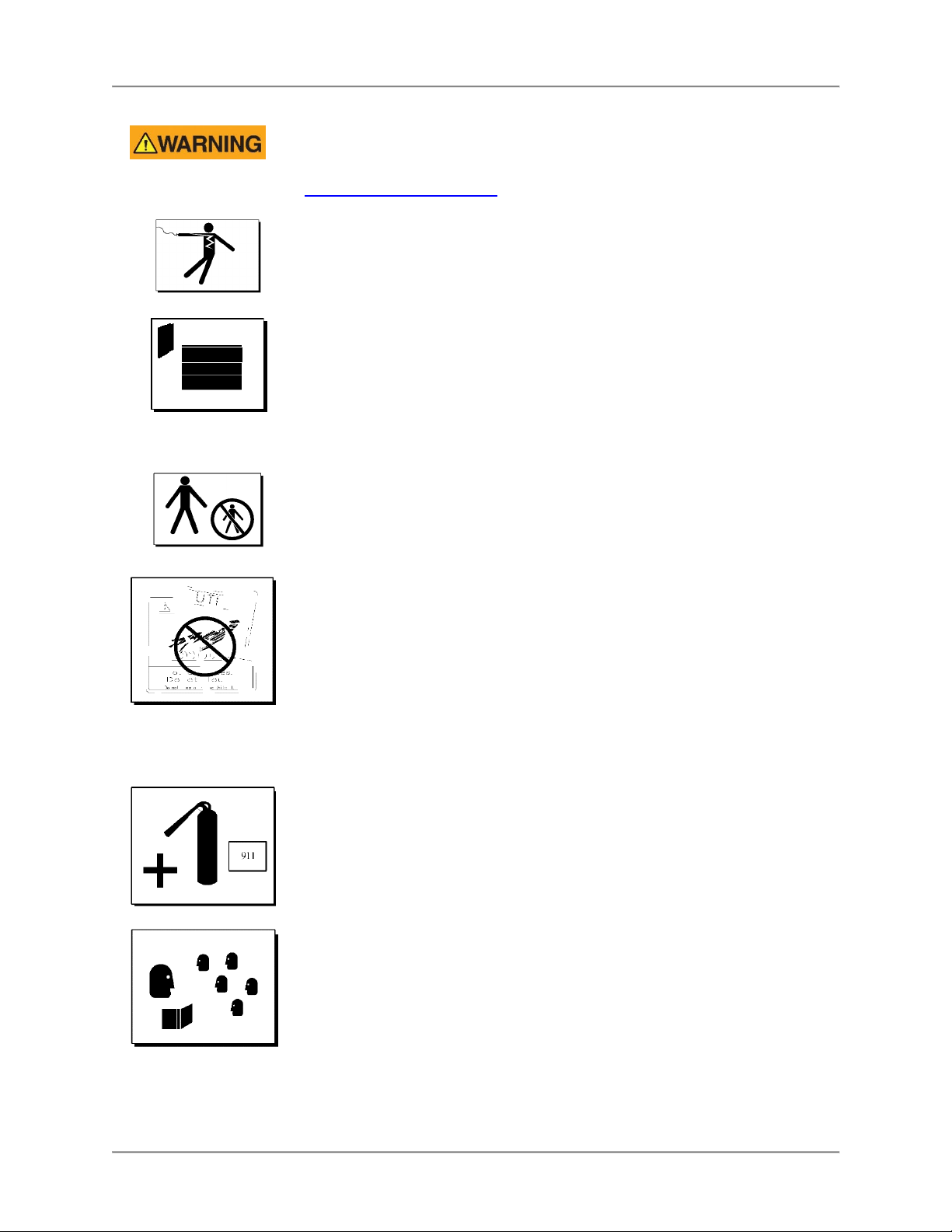
Safe Work Practices
chromium, and lead which are known to the State of California to cause cancer
and birth defects or other reproductive harm. For more information go to
www.P65Warnings.ca.gov.
This equipment uses high voltage. Serious injury can occur if you or any untrained or
unauthorized person installs, services, or repairs this equipment. Always Use an
Authorized Service agent to Service Your Equipment.
This manual is an important part of your equipment. Always keep it near for easy
access. If you need to replace this manual, contact:
BKI
Technical Services Department
2812 Grandview Drive, Simpsonville, S.C. 29680
Or call toll free: 1-800-927-6887 , Outside the U.S., call 864-963-3471
Keep children away from this equipment. Children may not understand that this
equipment is dangerous for them and others.
NEVER allow children to play near or operate your equipment.
Do not remove or cover any safety labels on your equipment. Keep all safety labels
clean and in good condition. Replace any damaged or missing safety labels. Refer to
the Safety Labels section for illustration and location of safety labels on this unit. If you
need a new safety label, obtain the number of the specific label illustrated on page
Error! Bookmark not defined., then contact:
BKI
Technical Services Department
2812 Grandview Drive, Simpsonville, S.C. 29680
Or call toll free: 1-800-927-6887, Outside the U.S., call 864-963-3471
Be prepared for fires, injuries, or other emergencies.
Keep a first aid kit and a fire extinguisher near the equipment. You must use a 40-
pound Type BC fire extinguisher and keep it within 25 feet of your equipment.
Keep emergency numbers for doctors, ambulance services, hospitals, and the fire
department near your telephone.
• Make certain your employees know how to operate the equipment.
• Make certain your employees are aware of the safety precautions on the
equipment and in this manual.
• Make certain that you have thoroughly trained your employees about operating the
equipment safely.
• Make certain the equipment is in proper working condition. If you make
unauthorized modifications to the equipment, you will reduce the function and
safety of the equipment.
3
Page 6

Mobile Merchandiser Operation
Operation
Safety Labels
CAUTION
Hot surface can cause
severe burns.
La surface Chaude peut
causer des brulures severes.
Ne pas toucher.
Do not touch.
N0645
Maximum Tank Capacity
13 gallons (49 liters)
Transfer oil from only (1) fryer
containing max.13 gal. (49 L)
[max. 100 lb. (45 Kg)] of oil.
DANGER
HIGH VOLTAGE.
Turn power off before
servicing. May have more than
one disconnec t switch.
HAUTE TENSIO N.
Mettez l'appareil ho rs tension avant
de proceder a l'e ntretien. Peut-etre
d'u commutateur de deconnexion.
Electrical G rounding Instructions
three-prong (grounding) plug for your protection again st shock hazard and should be
plugged direct ly into a properly g rounded three-prong receptacle. Do not cut or
remove the gr ounding prong from this plug.
Mise à la te rre
mise à la ter re assurant une pro tection contre les cho cs électriques. La pris e dans
laquelle elle est branchée doit êt re correctement mis e à la terre. Ne pas co uper ni
enlever la bro che de mise à la te rre de la fiche.
DO NOT COVER or REMOVE THIS LABEL NE RECO UVREZ PAS ou ENLE VEZ PAS CETTE ÉTI QUETTE
CAUTIO N
- This applia nce is equipped with a
AVERTIR
- Cet appare il est pourvu d’une fi che à trois broches don t une
4
Page 7

Mobile Merchandiser Operation
Item #
Description
Function
1
2
Controls
Operator controls for the Powered Disposal Caddy are located as illustrated in the diagram below.
Hardware Controls
1 Pump Power Switch Controls power to the onboard pump. When the Switch is placed
in the Extract position the pump will energize suctioning liquids
through the long hose into the onboard tank. When the Switch is
placed in the Discharge position the pump will energize suctioning
liquids out of the onboard tank out through the long hose. When
the Switch is placed in the center Off position the pump is deenergized.
2 Bypass Valve
(optional)
Controls liquid flow through or around the onboard pump. When
the handle is in the Onboard Pump position the pump can be
energize to transfer liquid to and from the onboard tank. When the
handle is in the Fill From Fryer position liquid can be pumped into
the onboard tank from a peripheral appliance such as a fryer.
5
Page 8

Mobile Merchandiser Operation
Extracting Renderings from an Oven Drawer
Ovens Equipped with Extraction Drawer and Coupler Nipple
1. Open the oven door and move the Disposal Caddy into position near the oven.
2. Lock at least (2) of the casters on the Disposal Caddy.
3. Plug the Disposal Caddy power cord into a 115V receptacle.
4. Put on high temperature gloves and any other protective equipment prescribed by your employer.
5. Move the Bypass Valve handle to the Onboard Pump position.
6. Connect the coupler on the end of the Disposal Caddy’s long hose to the nipple on the oven
Drawer. Make certain the coupler is fully seated on the nipple.
7. Move the Disposal Caddy Power Switch to the Extract position. The pump will start, suctioning
out the contents of the Drawer.
8. When the Drawer has been emptied move the Disposal Caddy Power Switch to the center Off
position.
9. Disconnect the Disposal Caddy hose coupler from the oven Drawer and stow it in the cup in the
onboard tank.
10. Unplug the Disposal Caddy power cord and stow it on the hanger on the back of the unit.
11. Release the caster brakes and move the Disposal Caddy to its storage location.
Ovens using the accessory Hand Wand
1. Open the oven door and move the Disposal Caddy into position near the oven.
2. Lock at least (2) of the casters on the Disposal Caddy.
3. Plug the Disposal Caddy power cord into a 115V receptacle.
4. Put on high temperature gloves and any other protective equipment prescribed by your employer.
5. Move the Bypass Valve handle to the Onboard Pump position.
6. Connect the coupler on the end of the Disposal Caddy’s long hose to the nipple on the Hand
Wand. Make certain the coupler is fully seated on the nipple.
7. Move the Disposal Caddy Power Switch to the Extract position. The pump will start.
8. Use the Hand Wand to suction out the contents of the Drawer
9. When the Drawer has been emptied move the Disposal Caddy Power Switch to the center Off
position.
10. Disconnect the Disposal Caddy hose coupler from the Hand Wand. Stow the hose coupler in the
cup in the onboard tank.
11. Unplug the Disposal Caddy power cord and stow it on the hanger on the back of the unit.
12. Release the caster brakes and move the Disposal Caddy to its storage location.
Discharge Fryer Oil into the Disposal Caddy
Transfer the oil from only one (1) fryer at a time into the tank. Completely discharge this oil from the
Disposal Caddy tank before transferring additional oil.
1. Open the fryer door and move the Disposal Caddy into position near the fryer.
2. Lock at least (2) of the casters on the Disposal Caddy.
3. Plug the Disposal Caddy power cord into a 115V receptacle.
4. Put on high temperature gloves and any other protective equipment prescribed by your employer.
5. Move the Bypass Valve handle to the Fill From Fryer position.
6. Connect the coupler on the end of the Disposal Caddy’s long hose to the nipple on the Fryer
filtration system. Make certain the coupler is fully seated on the nipple.
7. Start the Fryer filtration system to pump the oil into the Disposal Caddy onboard tank.
8. When the oil has been transferred to the Disposal Caddy turn the Fryer filtration pump Off.
9. Disconnect the Disposal Caddy hose coupler from the Fryer and stow it in the cup in the onboard tank.
10. Unplug the Disposal Caddy power cord and stow it on the hanger on the back of the unit.
11. Release the caster brakes and move the Disposal Caddy to its storage location.
6
Page 9

Mobile Merchandiser Operation
Discharging the Disposal Caddy Onboard Tank
Receptacles with a Coupler Nipple
1. Move the Disposal Caddy into position near the Receptacle connection.
2. Lock at least (2) of the casters on the Disposal Caddy.
3. Plug the Disposal Caddy power cord into a 115V receptacle.
4. Put on high temperature gloves and any other protective equipment prescribed by your employer.
5. Move the Bypass Valve handle to the Onboard Pump position.
6. Connect the coupler on the end of the Disposal Caddy’s long hose to the nipple on the
Receptacle plumbing. Make certain the coupler is fully seated on the nipple.
7. Move the Disposal Caddy Power Switch to the Discharge position. The pump will start,
suctioning out the contents of the onboard tank into the Receptacle.
8. When the onboard tank has been emptied move the Disposal Caddy Power Switch to the center
Off position.
9. Disconnect the Disposal Caddy hose coupler from the nipple on the Receptacle plumbing and
stow it in the cup in the onboard tank.
10. Unplug the Disposal Caddy power cord and stow it on the hanger on the back of the unit.
11. Release the caster brakes and move the Disposal Caddy to its storage location.
Receptacles using the accessory Hand Wand
1. Move the Disposal Caddy into position near the Receptacle connection.
2. Lock at least (2) of the casters on the Disposal Caddy.
3. Plug the Disposal Caddy power cord into a 115V receptacle.
4. Put on high temperature gloves and any other protective equipment prescribed by your employer.
5. Move the Bypass Valve handle to the Onboard Pump position.
6. Connect the coupler on the end of the Disposal Caddy’s long hose to the nipple on the Hand
Wand. Make certain the coupler is fully seated on the nipple.
7. Insert the Hand Wand in the Receptacle and hold it securely in place.
8. Move the Disposal Caddy Power Switch to the Discharge position. The pump will start,
suctioning out the contents of the onboard tank into the Receptacle.
9. When the onboard tank has been emptied move the Disposal Caddy Power Switch to the center
Off position.
10. Disconnect the Disposal Caddy hose coupler from the Hand Wand. Stow the hose coupler in the
cup in the onboard tank.
11. Unplug the Disposal Caddy power cord and stow it on the hanger on the back of the unit.
12. Release the caster brakes and move the Disposal Caddy to its storage location.
Operational Guidelines
• This appliance is not for use with products intended for human consumption.
• The onboard tank must be emptied and cleaned daily.
• Do not start the pump unless the hose is connected to an oven drawer, hand wand or receptacle
tank with a mating coupler nipple.
• Transfer the oil from only one (1) fryer at a time into the tank. Completely discharge this oil from
the tank before transferring additional oil.
7
Page 10

Mobile Merchandiser Installation
Installation
This appliance is equipped with a 3-prong grounding plug for your protection
against electrical shock hazard. It should be plugged directly into a properly
grounded 3-prong receptacle. Do not cut or remove the grounding prong from
this plug.
Instructions for Shipping Damage
You are responsible for filing all freight claims with the delivering truck line. Inspect all cartons and crates
for damage when they arrive. If there is damage noted to shipping crates or cartons, or, if a shortage is
found, note this on the bill of lading (all copies) before signing.
If damage is detected when the equipment is uncrated, immediately call the delivering truck line and
follow up the call with a written report indicating concealed damage to your equipment. Ask for an
immediate inspection of your concealed damage item. Crating material MUST be retained to show the
inspector from the truck line.
Location and Placement
After moving the unit into position lock the swivel casters before using.
Electrical Information
Electrocution, equipment failure or property damage could result if an unlicensed
electrician performs the electrical installation. Ensure that a licensed electrician
perform the electrical installation in accordance with local codes, or in the
absence of local codes, with the National Electrical Code, ANSI NFPA 70-20XX.
This appliance must be connected to a receptacle wired in accordance with all applicable local, state, and
federal codes. Use of an extension cord with this appliance is not recommended. It should be plugged
directly into a properly grounded 3-prong receptacle.
8
Page 11

Mobile Merchandiser Installation
PDC
-
14 & PDC
-
14B
Dimension
Uncrated
Crated
Electri
cal
Specifications:
PDC
-
14 & PDC
-
14B
Volts
Amps
Watts
Breaker
Dimensions & Specifications
386.8mm
15 1/4in
39 11/16in
1008.4mm
Height 39 11/16 in [1008.4 mm] 54 in [1372 mm]
Width 15 1/4in [386.8 mm] 32 in [813 mm]
Depth 29 5/8 in [752.3 mm] 44 in [1112 mm]
Floor Space 3.1 sq ft [0.29 m2] 9.8 sq ft [0.91 m2]
Weight 110 lb[50 kg] 160 lb [73 kg]
29 5/8in
752.3mm
120 5.6 670 15
9
Page 12

Mobile Merchandiser Maintenance
Draw Latch
Tank Drain
Tank Hose Coupler
Maintenance
Failure to comply with the maintenance below could result in a serious accident.
Electrocution, equipment failure or property damage could result if an unlicensed
electrician performs electrical repair. Ensure that a licensed electrician perform
electrical repair.
Scheduled Maintenance
Failure to remove power from this unit may cause severe electrical shock. This
unit may have more than one disconnect switch.
Always wear appropriate personal protection equipment (googles, rubber glove &
long sleeved garments) when cleaning the oven to guard against possible injury.
Using abrasive cleaners will damage the cabinet finish. Use only a mild soap and
water solution or cleaner approved for stainless steel.
DO NOT USE OVEN CLEANER on this machine. Caustic cleaners will cause
damage to the machine.
NEVER USE A WATER HOSE OR A STEAM CLEANER TO WASH THIS
UNIT. Excess water can get into the interior of the cabinet and cause damage.
Cleaning
For sanitary reasons this unit must be cleaned at
the end of each business day.
1. Make certain the Disposal Caddy power cord
is unplugged.
2. Disconnect the Tank Hose Coupler by lifting
up on release ring.
3. Remove the Onboard Tank from the Caddy.
4. Release the Draw Latch on each side of the
Onboard Tank and remove the Tank Lid.
5. Wash the inside and outside of the Onboard
Tank and Lid with a mild soap and water
solution, being sure to clean all areas. Open
the Tank Drain to aid in draining the Tank
during cleaning.
6. Wash the exterior of the Disposal Caddy with
a mild soap and water solution, being sure to
clean all areas..
7. Wipe the parts and unit dry with a soft, clean
cloth.
8. Make certain the Tank Drain is tightly closed.
9. Place the Tank Lid onto the Onboard Tank with the coupler nipple on the Lid oriented to the Drain
side of the Tank. Secure the Draw Latches on each side of the Tank.
10. Slide the Onboard Tank onto the Caddy with the Tank Drain oriented to the open end of the Caddy.
11. Connect Tank Hose Coupler to the nipple on the Onboard Tank.
ONBOARD
TANK
10
Page 13

Mobile Merchandiser Maintenance
Problem
Cause
Possible Solution
Troubleshooting
Refer to the table below for troubleshooting information.
Pump does not operate. Power supply cord is
disconnected.
Problem with building
power supply.
Pump motor thermal
overload tripped.
Defective power cord,
motor or other component.
Pump energizes but unit
does not transfer fluid.
Hose coupler not
Blockage in unit plumbing. Contact BKI authorized service agency
Bypass Valve set to Fill
From Fryer position.
completely connected.
Plug power supply cord into mating
receptacle.
Check circuit breaker at building power
panel. If problem persists, have
customer contact building maintenance
for corrective action.
Allow motor to cool 20 – 30 minutes then
press motor reset button on the back of
the unit below the motor.
Contact BKI authorized service agency.
Rotate Bypass Valve handle to the
Onboard Pump position.
Check the tank coupler and hose
coupler connections.
11
Page 14

Mobile Merchandiser Replacement Parts
Replacement Parts
Use the information in this section to identify replacement parts. To order replacement parts, call your
local BKI sales and service representative. Before calling, please note the serial number on the rating tag
affixed to the unit.
General
15
14
12
13
1
3
11
17
2
4
9
7
10
16
8
6
5
Item
Qty Part No. Description
1 1 AB16117200 ASSEMBLY, PUMP w/ BYPASS VALVE
2 1 H0135 HOSE, 1/2" ID x 35" HOT LIQUID
3 2 S0136 COUPLER, 1/2" NPTF
4 4 C0406 CASTER, 5" SWIVEL
5 1 CS0005 CORDSET, 14/3 x 90", NEMA 5-15
6 1 F0406 CORD GRIP, STRAIGHT, 025-038
7 1 S0104 SWITCH, RKR DPDT 15A 250V LAMP
8 1 R0197 RELAY, DPDT, 115V, 15A
9 2 TB0124 TERMINAL BLOCK, 2 CONDUCTOR
10 5 TB0123 TERMINAL BLOCK, 3 CONDUCTOR
11 1 MA16117100 HANDLE, VALVE
1 F0255 PIN, CLEVIS, 3/16 x 1-1/4
2 SP0014 SPACER, ALUM .5 X .125
1 F0254 PIN, COTTER HAIRPIN #213
12 1 WB16115200 WELDMENT, TANK
13 1 V0041 VALVE, DRAIN, 3/8 NPT
14 1 P0081 NIPPLE, QUIK DISCONNECT
15 1 AB16116200 ASSEMBLY, LID
16 1 FB16116903 COVER, PUMP
17 1 N0716 DECAL PDC-B OPERATION
12
Page 15

Mobile Merchandiser Replacement Parts
Pump with Bypass Valve
7
8
3
10
6
2
5
11
1
4
Item Qty Part No. Description
1 1 M0047 PUMP / FILTER ASSEMBLY
9
2 1 V0040 VALVE, 1/2" BALL
3 1 LZ0105 FILL VALVE BRACKET
4 1 H0172 HOSE, 1/2" ID x 14" OAL
5 1 TU0205 TUBING, 12" 1/2" ID
6 2 FT0536 COUPLING, 1/2" MPT x FLARE
7 2 FT0643 TEE, 1/2" BLACK IRON
8 2 FT0235 NIPPLE, 1/2" x CLS,
9 1 FT0132 ELBOW, 1/2 STREET x 90
10 1 FT0644 NIPPLE, 1/2" x 3"
11 1 F0155 BUSHING, 7/8" SNAP (BLACK)
Tank Lid
2
1
3
Item Qty Part No. Description
1 1 WB16115900 WELDMENT, PDC LID
2 1 TP0041 TAPE, 1/16 x 1/2 SILICONE
3 1 MA16116000 TUBE, PICKUP
13
Page 16

Mobile Merchandiser Replacement Parts
EXTRACTION DRAWERS for OVENS
PART NO.
DESCRIPTION
HAND WAND ASSEMBLY
Accessories
AA16117400
AB16117400 HAND WAND
AB55013300 VGG8 ROTISSERIE OVEN
AB55013700 VGG5 ROTISSERIE OVEN
AB10231800 102 COMBI OVEN
AB10232100 101 COMBI OVEN
14
Page 17

Mobile Merchandiser Wiring Diagram
Wiring Diagram
SB16190200
WRITTEN PERMISSION FROM STANDEX CSG. ALL RIGHTS ARE RESERVED.
THE COMBINATION OF FACTS, DATA, DESIGN ELEMENTS, ENGINEERING
CONTAINED IN THIS DRAWING ARE OF A PROPRIETARY NATURE TO BKI.
THESE MATERIALS ARE NOT TO BE USED OR COPIED WITHOUT PRIOR
DATA, MANUFACTURING DATA AND ASSEMBLY DATA WHICH MAY BE
Drawing Number
REV ECO DESCRIPTION DATE
3
T5
T4
T2
M1
T3
P2
1
1
L1
L2
T8
P1
3
L2
L2
T5
T8
3
T8
R1
23
T5
1
L2
L1
BLK
110-120V
WHT
1 Ph
CS1
0.7 1531PDC-14
KILLOWATTS
120 5.6
VOLTAGEPHASE AMPSNO. of WIRES BREAKER SIZE
S1
Model
LEGEND
F 04 06 CORD RE STR AINT
M 1 - M0 0 47 MO T OR/ PUM P, 115 /23 0V
R 1 - R01 97 REL AY, DP D T, 115 V
CS 1- 12 0V - C S000 5 C ORD S ET, 8 6" N EMA 5- 20
S 1- S01 0 4 S WIT CH, RO C KER , D PDT
TAH 3/29/2018
Drawn By Date
15
Page 18

Mobile Merchandiser Notes
Notes
2812 Grandview Dr., Simpsonville, S.C. 29680, USA
http://www.bkideas.com
Made and printed in the U.S.A
Page 19

Mobile Merchandiser Notes
REVISION
DATE
REVISED BY
DESCRIPTION
REVISION HISTORY
01 03/27/13 KW Initial Release-Supersedes all previous
releases
 Loading...