

Page 1
TECHNICAL
TRAINING
COURSE
REV. 01/2015
USA
IT | GB
Page 2

2
TECHNICAL TRAINING COURSE
INDEX
1.0 OVEN INSTALLATION 4
1.1 POSITIONING 4
1.2 Water connection 4
1.3 Drain connection 5
1.4.1 Electric connection 5
1.4.2 Electric connection 6
1.5 Gas connection (gas ovens only) 6
1.6 Fumes exhaust 7
1.7 Adjust trolley of 20 1/1 and 20 2/1 ovens 8
2.0 OVEN START-UP 8
3.0 ELECTRICAL COMPONENTS IDENTIFICATION 9
3.1 Water electrovalves and injector codication (EU,EV,EL,ES,EA,ESH) 9
3.2 Transformers 10
3.3 Door micro-switch - SP 10
3.4 Resistance Elements contactor - KR 10
3.5 Motor thermal protection 11
3.6 Motor Inverter - power supply relay 11
Page
3.7 Fuses 11
3.8 Automatic security thermostat of the boiler 11
3.9 Cavity security thermostat - F1 12
3.10 Water pressostat - PA (direct steam oven with washing system) 12
3.11 Meteo System probes 12
3.12 EMC lters - PFC, FLC 12
3.13 Air pressostat - P1 (gas ovens) 13
3.14 Gas blower - MB, control board PWM 13
3.15 Burner control - IGN 13
3.16 Gas valve - EVG 13
3.17 Motorized discarging valve - MS 14
3.18 Washing pump - PL 14
3.19 Detergent pump - PD 14
3.20 Flowmeter - HALL 14
3.21 Buttery valve - MV 15
4.0 GAS OVEN - SETUP 15
4.1 Combustion analysys 15
4.2 Gas reference table 18
4.3 Setting ignition probes and detecting ame probe 18
4.4 Gas change procedure 19
4.5.1 Fixing the burner to the exchanger : GASKET SEQUENCE 21
4.5.2 Fixing the burner to the exchanger : NOTES 22
5.0 ELECTRONIC BOARDS and congurations 23
5.1 Conguration of electronic boards serial connections 24
Page 3

TECHNICAL TRAINING COURSE
3
INDEX
5.2 I-O Check 26
5.2.1 I-O Check - Probes 26
5.2.2 I-O Check - Digital inputs 27
5.2.3 I-O Check - Digital outputs 28
5.3 HACCP recording (touch board) 29
5.3.1 Cooking log memorisation 29
5.3.2 Print-out example 29
5.3.3 HACCP parameters 29
5.3.4 Download HACCP log ---> USB pen drive 30
5.4 Wash log - download - erase 30
5.5 Upload-download recipes 31
5.5.1 Upload recipes 31
5.5.2 Download recipes 31
5.6 Wash log - download - erase 32
5.7 ALARMS DESCRIPTION 33
5.8 Alarm log - download - erase 34
5.9 System info menu 35
Page
5.10 Inverter alarm signal diagnostic 35
5.11 Technical parameters 36
5.12 Firmware upgrade 37
5.13.1 Upload new parameters 38
5.13.2 Download parameters le from the oven 38
5.13.3 Upload new parameters 39
5.13.4 Download parameters from the oven 40
6.0 MAINTENANCE 41
6.1 Boiler descaling 41
6.2 Cleaning oven cavity 43
6.3 Cleaning panel air lter 44
6.4 Adjustment of the hinges and the closing pivot of the door 44
6.5 Changing door lights and glass cleaning 45
6.6 Washing sprinkler cleaning 45
7.0 SPECIAL MAINTENANCE 46
7.1 Boiler opening and check 46
7.2 Fans replacement
7.3 Door gasket replacement
7.4 Complete door handle replacement
8.0 ELECTRICAL DRAWINGS
9.0 SPARE PARTS EXPLODED VIEW
47
51
52
54
62
Page 4
4
TECHNICAL TRAINING COURSE
1 INSTALLATION
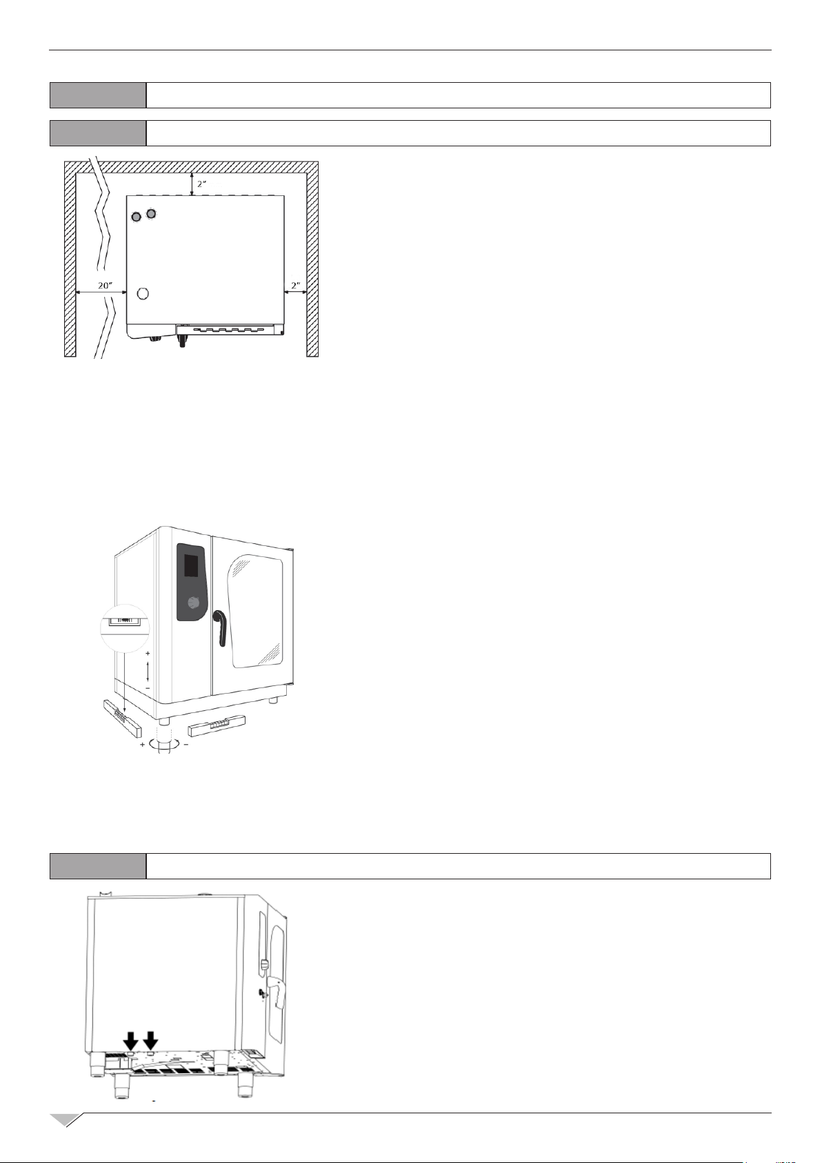
1.1 POSITIONING
The appliances have been designed for installation in
closed premises, they cannot be used in the open air
and cannot be exposed to rain.
The place of installation of the oven must have a solid,
at and horizontal surface able to safely support both
the mass weight of the appliance/support and that of
maximum load capacity.
The appliance must be placed in adequately ventilated
premises.
The oven must only be installed on a stable support. The appliance must be removed from its
packaging, its integrity checked and arranged in the place of use, being careful not to position it
above or against walls, sides, partition walls, kitchen cabinets or covers in ammable material.
We recommend scrupulously complying with the reproof Standard in force.
There must be a minimum distance of 2” on all sides
between the oven and the walls or other equipment.
We recommend leaving 20” of space between the left
side of the oven and the corresponding room wall, for
easy oven installation and its subsequent maintenance.
All materials used for packaging are compatible with
the environment; they must be safely kept and disposed of according to the Standard in force.
The oven must be levelled: to regulate the height of
the adjustable feet act, using as reference a spirit le-
vel. Signicant unevenness or inclinations can negatively inuence the functioning of the oven. Slowly remove all protective lm from the appliance
external panels, being careful not to leave traces of adhesive. Check that the heat disposal or
inlet slots and openings are not obstructed.
1.2
WATER CONNECTION
The water pressure must be max. 6 bar. Should the wa-
ter pressure from the mains be higher than such value,
install a pressure reducer upstream of the oven. The
minimum water temperature for the correct functioning
of the oven must be higher than 0.5 bar. The oven has a
softened water inlet. Always install a water softener to
bring the hardness of the water at appliance inlet within
the values of between 5 TH and 10 TH. If the oven is
equipped with automatic washing system and the water
hardness is greater then 10 TH it racommanded to use
softened water for the second water inlet. Connect the
Page 5
TECHNICAL TRAINING COURSE
"Water" duct to the specic cold water mains, and interpose a shut-off cock and lter. Before
connecting, let sufcient amount of water ow to clean the duct from any iron residues.
Ensure the shut-off cock is located in a place and in a manner to be easily activated at any
momentby the operator.
Attention: in case of water drain pipe fault, it must be replaced with a new one and the old and
faultyone must never be re-used.
5
1.3
1.4.1
The electric system, as prescribed and specied by the Standard in force, must be equipped
Have professionally qualied staff check that the plug cables section is adequate to the power
absorbed by the appliance.
Loosen the screws xing the left side of the oven and extract it.
Place the power supply cable inside the cable gland hole in the lower part, on the left of the
oven.Connect the cable to the terminal board following the indications on “tab 1”.
Lock the cable with the cable gland.
ELECTRIC OVENS GAS OVENS
L1 L2 L3 N L N X
tab 1
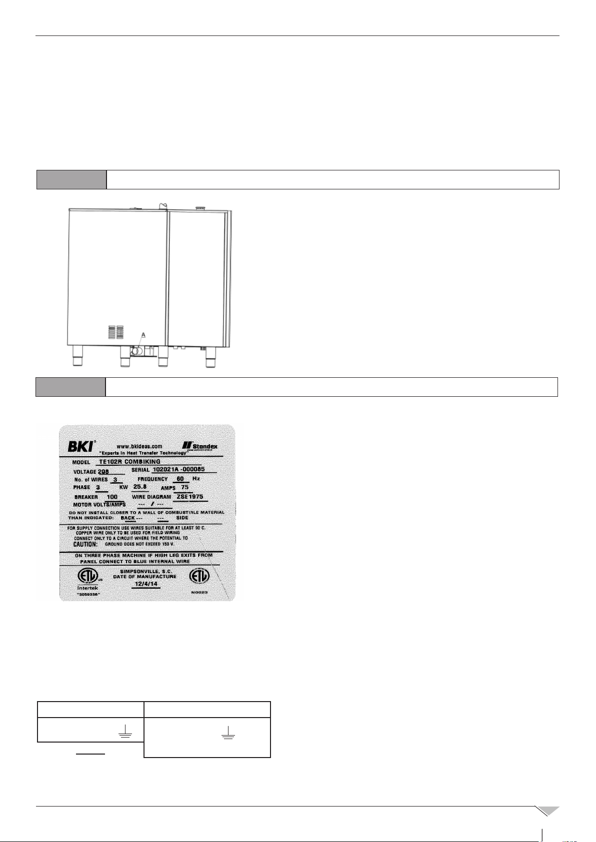
DRAIN CONNECTION
The oven is equipped with a water draining device;such
device is located at the bottom in the rear part of the
appliance and has a tube with a 2” diameter.
Connect the tube that protrudes from the draining device .The draining device is a siphon; we recommend
connecting the tube on an open funnel.
Check that the internal siphon is full of water and, if
not, ll it by introducing water through the drain in the
cooking compartment.
ELECTRIC CONNECTION
with an efcient ground. It is possible to guarantee the
electric safety of the appliance only in the presence of
Standard electric system.
For direct connection to the mains it is necessary to interpose a device between the equipment and the same
mains, dimensioned depending on the load, that ensures
its disconnection and which contacts have an opening
distance enabling the full disconnection, in compliance
with the installation regulations; this device also must be
located in a place and in a manner to be easily accessible
at any moment by the operator.
Bring the main switch, to which the power supply cable
plug will be collected, in position 0 (zero).
The power supply voltage with machine
funcioning,must not be different from the nominal
voltage value of ±10%.
Page 6
6
TECHNICAL TRAINING COURSE
1.4.2
When a high current ows through a conductor, differences in potential appear between the
conductor and nearby metallic surfaces near the appliance. As a result, sparks may be produ-
ced between the appliance and surrounding metal surfaces. These sparks could cause serious
injury, damage, or re.
BKI provides an Equipotential ground terminal for the connection of a bonding conductor after
the installation of the appliance per lEC60417-1. This terminal is located on the inside of the
Power Entry Supply box near the Earth connection and is marked with this symbol:
For gas ovens, complete gas connection to the appliance before assembling
the oven side again; for electric ovens assemble the oven side.
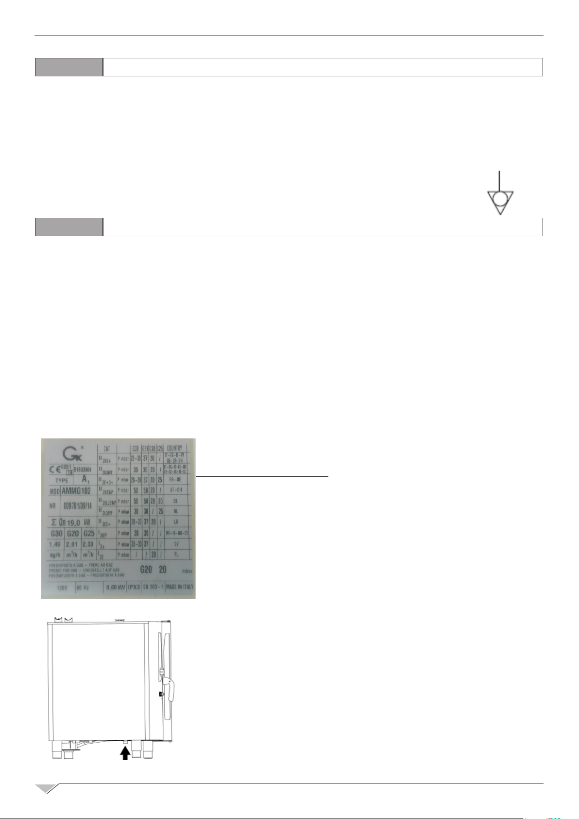
1.5
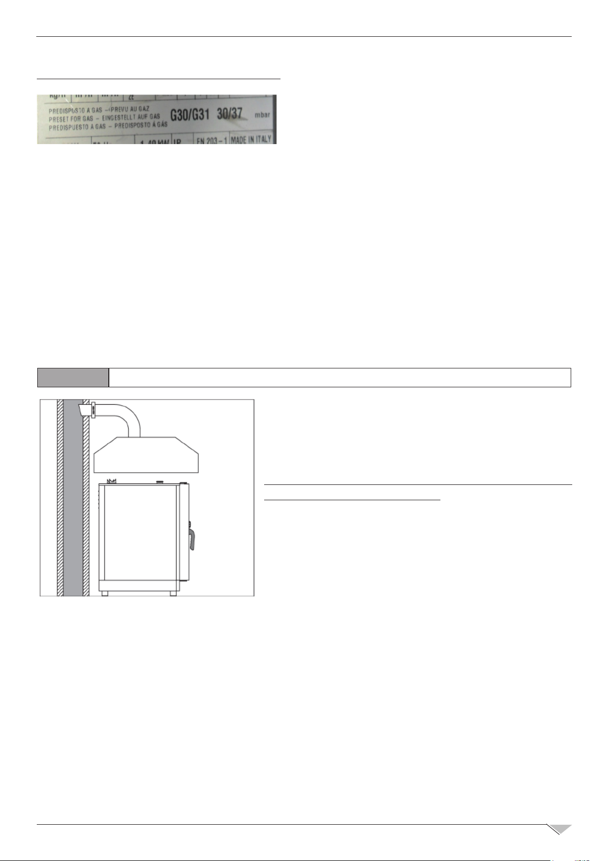
The oven is originally calibrated for functioning with the gas type specied during ordering.
The type of gas for which the oven is adjusted is reported on the technical place on the appliance
During testing, ascertain the factory calibrations carried out on the burners are appropriate for
the specic installation type, by means of analysis of the gases produced by combustion (CO2
and CO) and check of the thermal capacity.
Specically, with oven functioning at full capacity, the values of the undiluted CO present during
draining, must be within 300 ppm (normally a well calibrated pre-mix system does not produce
CO which mean the value should be 0).
If the presence of undiluted CO over such limit is detected, the adjustment of the burners must
be checked by a technician authorised by the manufacturer, who will make all due amendments
ELECTRIC CONNECTION
GAS CONNECTION (GAS OVENS ONLY)
to the devices governing combustion and to the relative parameters. The detected data must be
recorded and become integrating part of the technical documentation of that appliance.
Installation prescriptions
The oven installation and commissioning operations must be
carried out only by qualied staff according to regulations and
standards in force.
The gas systems, the electric connections and the installation
premises of the appliances must be compliant with regulations
and Standards in force.
Bear in mind that the air necessary for combustion of the burners
is of 2 m3/h per kW of installed power.
In activities open to the public, the Standards for the safety
prevention of accidents and re and panic must be complied with.
The connection to the gas supply tting can be carried out using
exible metal piping, interposing an approved shut-off cock in an
easily accessible point.
Ensure that the exible metal connection tube to the gas inlet
tting does not touch overheated parts of the oven and that it is
not submitted to torsion or extension stresses.
Use securing clips compliant with installation Standards.
Page 7
TECHNICAL TRAINING COURSE
Checks to be carried out before installation
On the technical plate located on the left side of the
oven check that the appliance has been tested for
the type of gas available with the user.
Check the data on the technical plate that the pressure reducer capacity is sufcient for powering
the equipment.
Avoid interposing section reductions between the reducer and the appliance.
We recommend mounting a gas lter upstream of the pressure regulator to guarantee optimal
oven functioning.
Connect the oven to the gas supply system by means of special 1/2” NPG tube.
After gas connection, check there are no leaks on the joints and ttings. For this purpose, use
soapy water or a specic foamy product to detect leaks.
It is opportune for the routine maintenance of the gas ovens to be carried out yearly, in
compliance with specic Standards, by an authorised technician; during which the fuel gas will
be analysed and the thermal power checked.
7
1.6
a) the extracted volume must be above that of the generated fuel gas (see Standard in force);
b) the material with which the hood lter is made must resist the fuel gas temperature that, at
conveyor outlet, can reach 572°F;
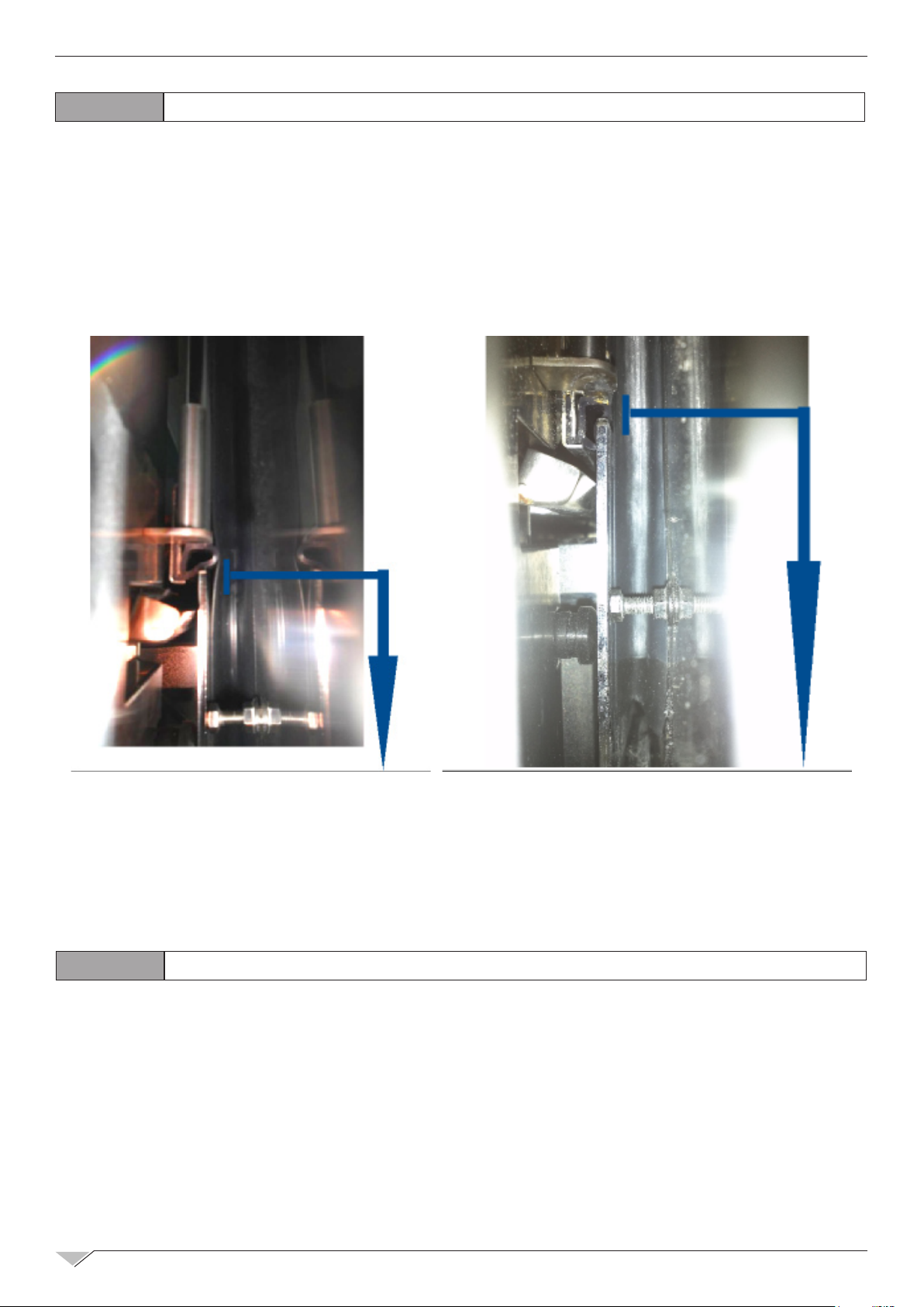
FUMES EXHAUST
In compliance with installation Standards, the ovens
must be started in premises suitable for evacuation of
the combustion products.
It is possible to connect the ue passage by means
of a forced evacuation system, like a hood equipped
with mechanical extractor fan. In this case, the gas
supply to the appliance must be directly controlled by
such system and must interrupt should capacity drop
below the prescribed values. When the appliance is
installed underneath the extractor hood, check that
the following indications are complied with:
c) the end of the evacuation duct of the appliance must be positioned inside the projection of
the hood base perimeter;
d) the re-admission of the gas to the appliance must only be possible manually.
Page 8
8
TECHNICAL TRAINING COURSE
1.7
A correct adjustment of the coupling between trolley and oven allows to prevent steam or water
leakage, when the trolley is inserted inside the oven with the door closed.
1. The oven must be levelled to allow the edge of the sheet metal seal of the trolley to remain
about 3 mm under the glass limit of the oven door.
2. Then screw spacers must be adjusted between the front and the stop of the trolley, at
13 - 15 mm height.
ADJUST TROLLEY OF 20 1/1 AND 20 2/1 OVENS
NO
In this picture the gasket placed under
the glass is too compressed and so the
front gasket crushes until drawing.
2.0
Before commissioning the oven, scrupulously carry out the necessary checks to ensure the
compliance of the systems and installation of the appliance with the legal Standards and
technical and safety indications in the user manual.
The following points must also be satised:
• The ambient temperature of the place of installation of the oven must be higher than 4°F.
• The cooking compartment must be empty.
• All packaging must be fully removed, including the protective lm applied on the oven walls.
• The air vents and louvers must be open and not obstructed.
• The eventually dismantled oven pieces must be, for installation purposes, re-mounted.
• The main electric switch must be closed and the water and gas shut-off cocks upstream of
the appliance must be open.
OVEN START-UP
In this picture the distance between the trolley
and the door glass has been reduced, the gasket
is less compressed and it does not overhang. In
this way the front gasket does not deform itself.
YES
Page 9
TECHNICAL TRAINING COURSE
9
3.0
3.1
ELECTRICAL COMPONENT IDENTIFICATIONS
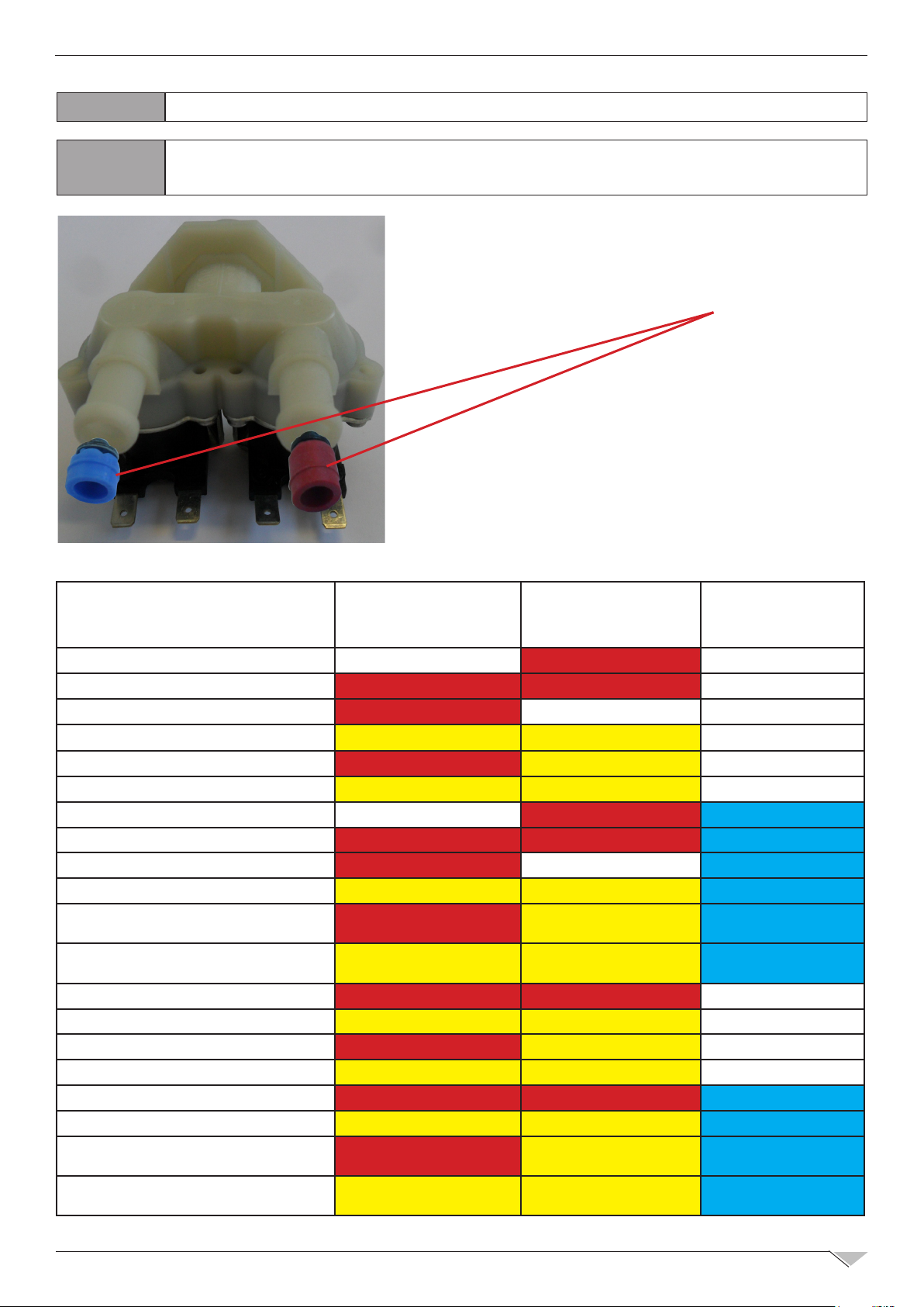
WATER ELECTRO-VALVES AND INJECTOR CODIFICATION
(EU, EV, EL, ES, EA, ESH)
The solenoid valve is the device that supplies water in
the pre-established times and methods.
At the electro-valve outlet a injector (nozzle) is normally
applied.
STEAMBOX VALVE, NOZZLE:
HUMIDIFIER
BOILER
(VER. ‘H’ ONLY)
WASHING
SYSTEM
ABHE061 BROWN 0,07 ÷ 0,14 L/min RED 0,2 ÷ 0,3 L/min NO WASH. SYS.
ABHE062-101 RED 0,2 ÷ 0,3 L/min RED 0,2 ÷ 0,3 L/min NO WASH. SYS.
ABTE061-062-101 RED 0,2 ÷ 0,3 L/min
ABTE102-ABHE102
YELLOW 0,32 ÷ 0,42 L/min
ABTE201-ABHE201 2 X RED 0,2 ÷ 0,3 L/min
ABTE202-ABHE202
2 X YELLOW 0,32 ÷ 0,42 L/min YELLOW 0,32 ÷ 0,42 L/min
ABHE061R BROWN 0,07 ÷ 0,14 L/min RED 0,2 ÷ 0,3 L/min
ABHE062R-ABHE101R
ABTE061R-ABTE061R-062R-101R
ABHE102R
RED 0,2 ÷ 0,3 L/min RED 0,2 ÷ 0,3 L/min
RED 0,2 ÷ 0,3 L/min
YELLOW 0,32 ÷ 0,42 L/min
ABTE201R-ABHE201R 2 X RED 0,2 ÷ 0,3 L/min
ABTE202R-ABHE202R
2 X YELLOW 0,32 ÷ 0,42 L/min
NO BOILER
YELLOW 0,32 ÷ 0,42 L/min
YELLOW 0,32 ÷ 0,42 L/min
NO WASH. SYS.
NO WASH. SYS.
NO WASH. SYS.
NO WASH. SYS.
BLU 4,5 ÷ 6 L/min
BLU 4,5 ÷ 6 L/min
NO BOILER BLU 4,5 ÷ 6 L/min
YELLOW 0,32 ÷ 0,42 L/min
YELLOW 0,32 ÷ 0,42 L/min
YELLOW 0,32 ÷ 0,42 L/min
BLU 4,5 ÷ 6 L/min
BLU 4,5 ÷ 6 L/min + 2
NERO 1,9 ÷ 3,5 L/min
BLU 4,5 ÷ 6 L/min + 2
NERO 1,9 ÷ 3,5 L/min
ABHG061-062-101 RED 0,2 ÷ 0,3 L/min RED 0,2 ÷ 0,3 L/min NO WASH. SYS.
ABHG102
YELLOW 0,32 ÷ 0,42 L/min
ABHG201 2 X RED 0,2 ÷ 0,3 L/min
ABHG202
2 X YELLOW 0,32 ÷ 0,42 L/min
ABHG061R-062R-101R RED 0,2 ÷ 0,3 L/min RED 0,2 ÷ 0,3 L/min
ABHG102R
YELLOW 0,32 ÷ 0,42 L/min
ABHG201R 2 X RED 0,2 ÷ 0,3 L/min
ABHG202R
2 X YELLOW 0,32 ÷ 0,42 L/min
YELLOW 0,32 ÷ 0,42 L/min
YELLOW 0,32 ÷ 0,42 L/min
YELLOW 0,32 ÷ 0,42 L/min
YELLOW 0,32 ÷ 0,42 L/min
YELLOW 0,32 ÷ 0,42 L/min
YELLOW 0,32 ÷ 0,42 L/min
NO WASH. SYS.
NO WASH. SYS.
NO WASH. SYS.
BLU 4,5 ÷ 6 L/min
BLU 4,5 ÷ 6 L/min
BLU 4,5 ÷ 6 L/min + 2
NERO 1,9 ÷ 3,5 L/min
BLU 4,5 ÷ 6 L/min + 2
NERO 1,9 ÷ 3,5 L/min
Page 10
10
TECHNICAL TRAINING COURSE
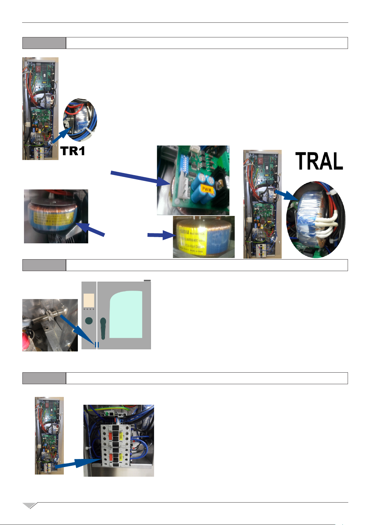
3.2
TRANSFORMERS
TR1 – Electronic board transformer (for main card and power cards): power 17 VA, PRY 230
Volts - SEC 2 x 12Volt (12VA + 5VA)
TR2-TR3 – PWM card and fan blower transformer: power 60 VA, PRY 230 Volts - SEC
24Volt.
TRAL - Halogen light transformer: power 60 VA , PRY 230 Volts - SEC 12 Volt
TRAF (ELE ovens) -
TRAF (GAS ovens) -
TR2
Main power supply transformer: power 250 VA , PRY 208 Volts - SEC 230 Volt
Main power supply transformer: power 1500 VA , PRY 120 Volts - SEC 230 Volt
3.3
3.4
TRAF
DOOR MICRO-SWITCH - SP
The door micro-switch is a magnetic type. The magnet is applied
inside the door. The sensor is xed inside the main control panel.
RESISTANCE ELEMENTS CONTACTOR - KR
KR 1/3 = 1 elements of the resistance
KR 2/3 = 2 elements of the resistance
FULL POWER = KR 1/3 + KR 2/3
or
KR 1/2 = 1/2 elements of the resistance
KR 2/2 = all elements of the resistance
FULL POWER = KR 1/2 + KR 2/2
Page 11

TECHNICAL TRAINING COURSE
11
3.5
3.6
The Inverter CARD INV control the functionament of the oven motor/s.
The Relay K0 switch on/off the main power supply of the Inverter.
MOTOR THERMAL PROTECTION
The white wires are connected to a temperature
sensor inside the motor (clikson)
MOTOR INVERTER - POWER SUPPLY RELAY - FUSE
FU3/FU4): Inverter power supply
protection->T10A (slow blow)
3.7
FU0 : Power supply transformer protection
TRAF 208/230 250VA -> T2A (slow blow)
TRAF 120/230 1500VA -> T15A (slow blow)
FU1 or FU2: gas burner control protection ->F2A (fast)
FU5 : Main board transformer protection (TR1)->T200mA (slow blow)
FU6 : Light transformer protection (TRAL)->T315mA (slow blow)
FU7 : Pwm board transformer protection (TR2)->T315mA (slow blow)
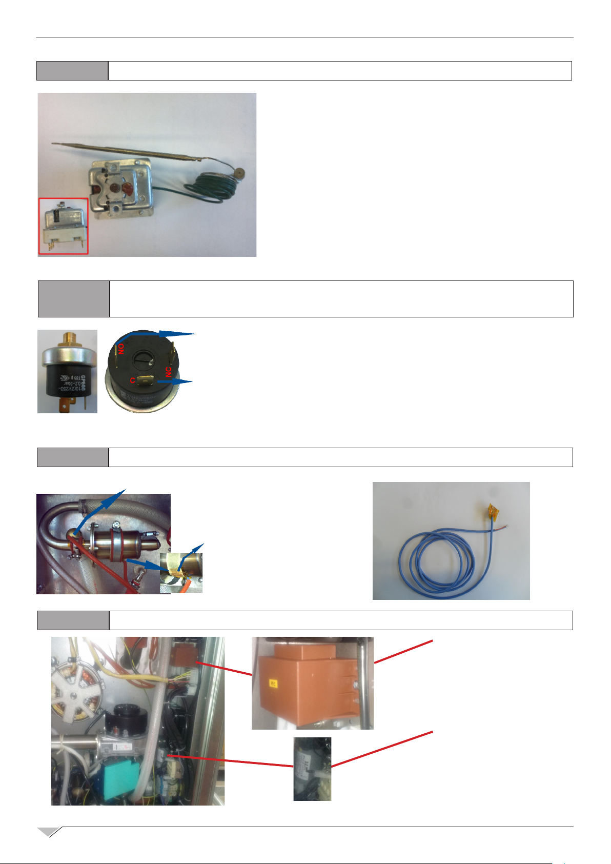
3.8
FUSES
AUTOMATIC SECURITY THERMOSTAT OF THE BOILER
The automatic security thermostat prevent functioning
of the boiler without water. It reset itself.
1
BOILER ELEMENTS PHASE CONNECTION
P(L)
ELECTRONIC BOARD RELAY
Page 12
12
TECHNICAL TRAINING COURSE
3.9
3.10
CAVITY SECURITY THERMOSTAT - F1
If the temperature inside the cooking compartment
reaches 662°F, the safety thermostat interrupts supply
to the oven’s heating elements.
To reset it push the red (or brown) button.
WATER PRESSOSTAT - PA (DIRECT STEAM OVEN WITH
WASHING SYSTEM)
CONTROL
LEVEL BOARD
Connect ‘C’ plug to the ground cable and ‘NO’ plug to
main board control level.
3.11
3.12
GROUND
METEO SYSTEM PROBES
ALARM PROBE 4: UPPER PROBE
FOR METEO SYSTEM
ALARM PROBE 5: LOWER PROBE
FOR METEO SYSTEM
EMC FILTERS - PFC, FLC
PFC = Inductance
for Harmonic noise of
Inverter
FLC = Line lter
Page 13
TECHNICAL TRAINING COURSE
13
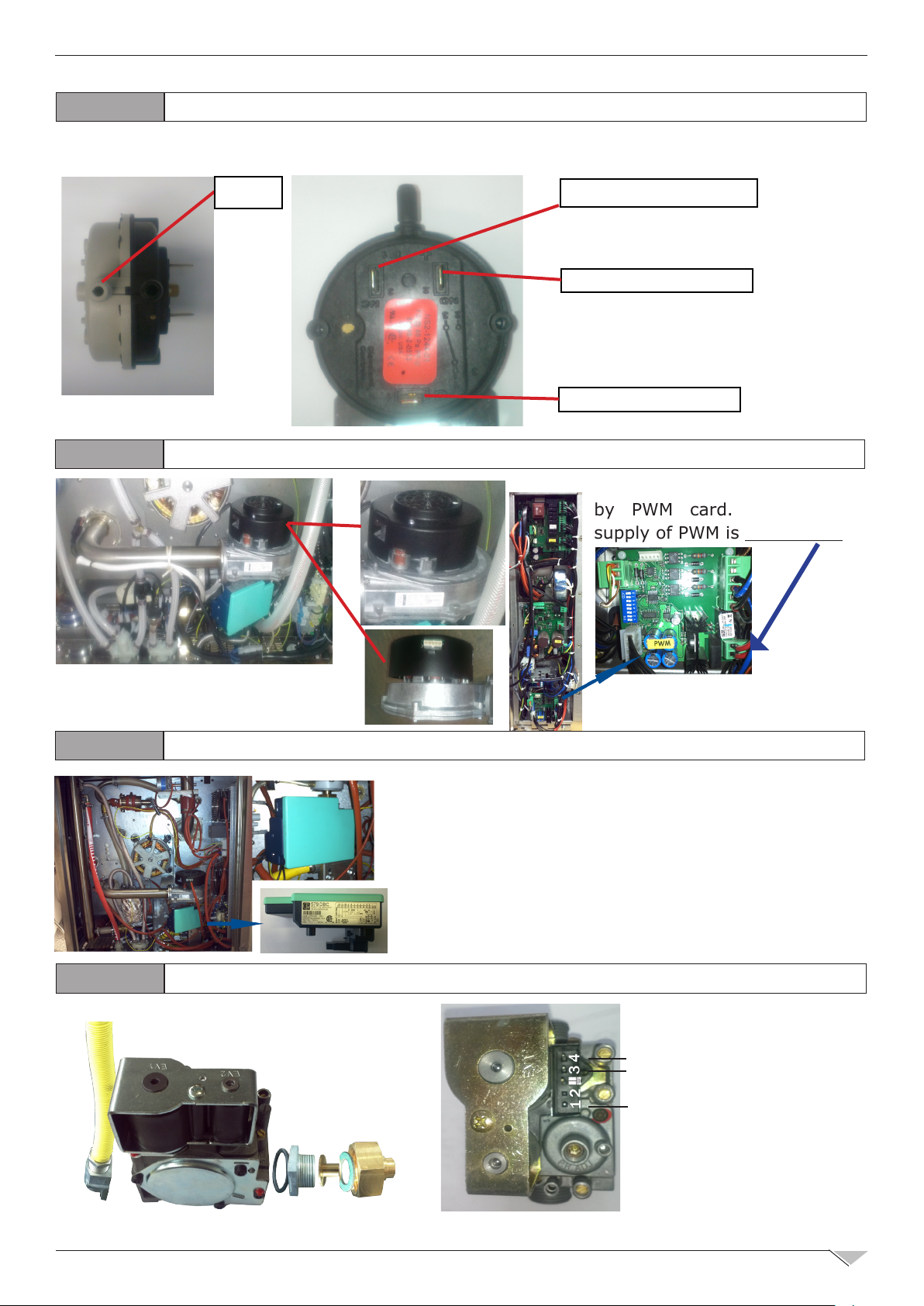
3.13
The air pressostat control the correct chimney evacuation
AIR PRESSOSTAT - P1 (gas ovens)
AIR
3.14
GAS BLOWER - MB / CONTROL BOARD - PWM
NC/2 : disconnected
NO/2 : connected
C/1 : connected
The gas blower is controlled
by PWM card. The power
supply of PWM is 24Volt - AC.
3.15
3.16
BURNER CONTROL - IGN
This electronic card switch on the burner (make the
spark between two probes) and also detect the ame
with a special probe.
GAS VALVE - EVG
Coil functionality test:
To verify the coils
600Ω (3-4)
3,7kΩ (3-1)
functionality must be
measured resistance
values. Please see
reference values
(cold coil)
Page 14
14
TECHNICAL TRAINING COURSE
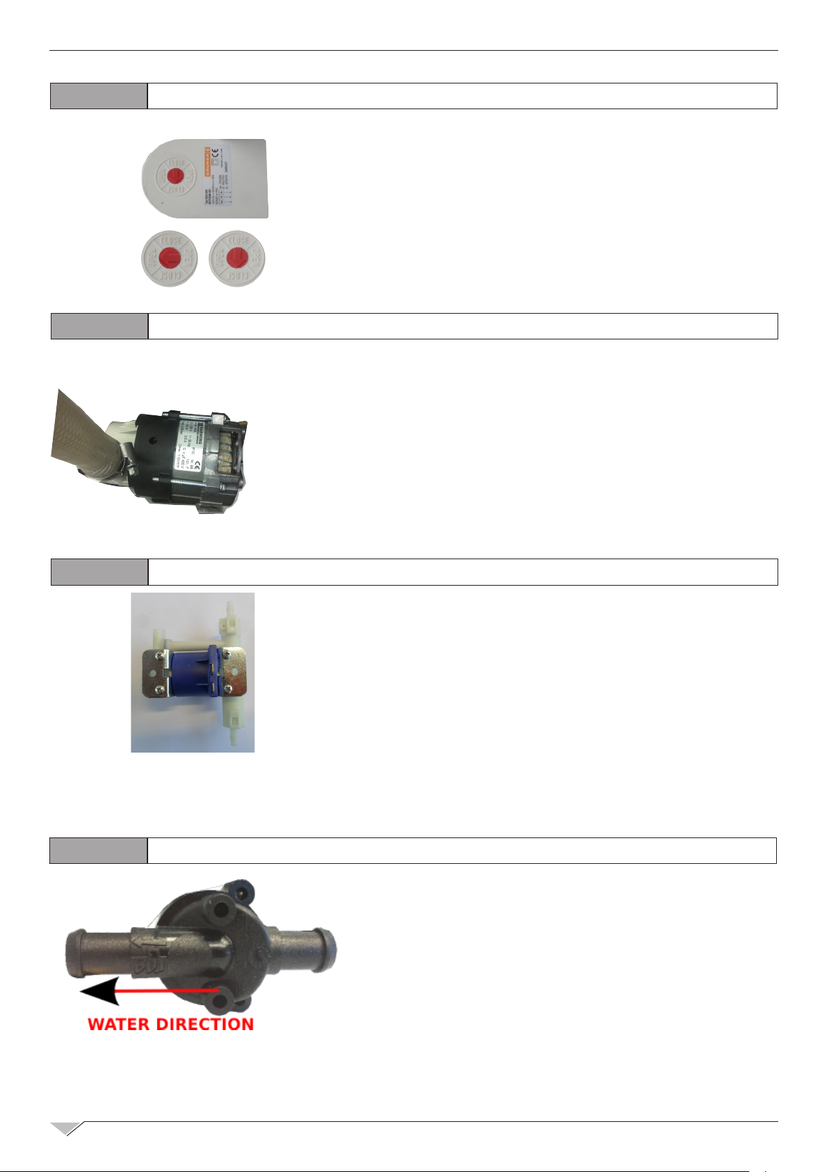
3.17
3.18
MOTORIZED DISCARGING VALVE - MS
Automatic operations:
Cooking mode : valve open
Automatic washing mode : valve close
WASHING PUMP - PL
The washing pump working when the water discarge is
closed and a ll of water is charged in the cavity. It’s
termically protected and the reset is automatic when
the temperature of the pump cool down.
3.19
3.20
DETERGENT PUMP - PD
Detergent pump for the automatic washing system.
FLOWMETER WASHING SYSTEM
The owmeter control the quantity of water is load
during a washing cycle.
Page 15
TECHNICAL TRAINING COURSE
Rigenerazione
Cottura manuale Rigenerazione
Service
15
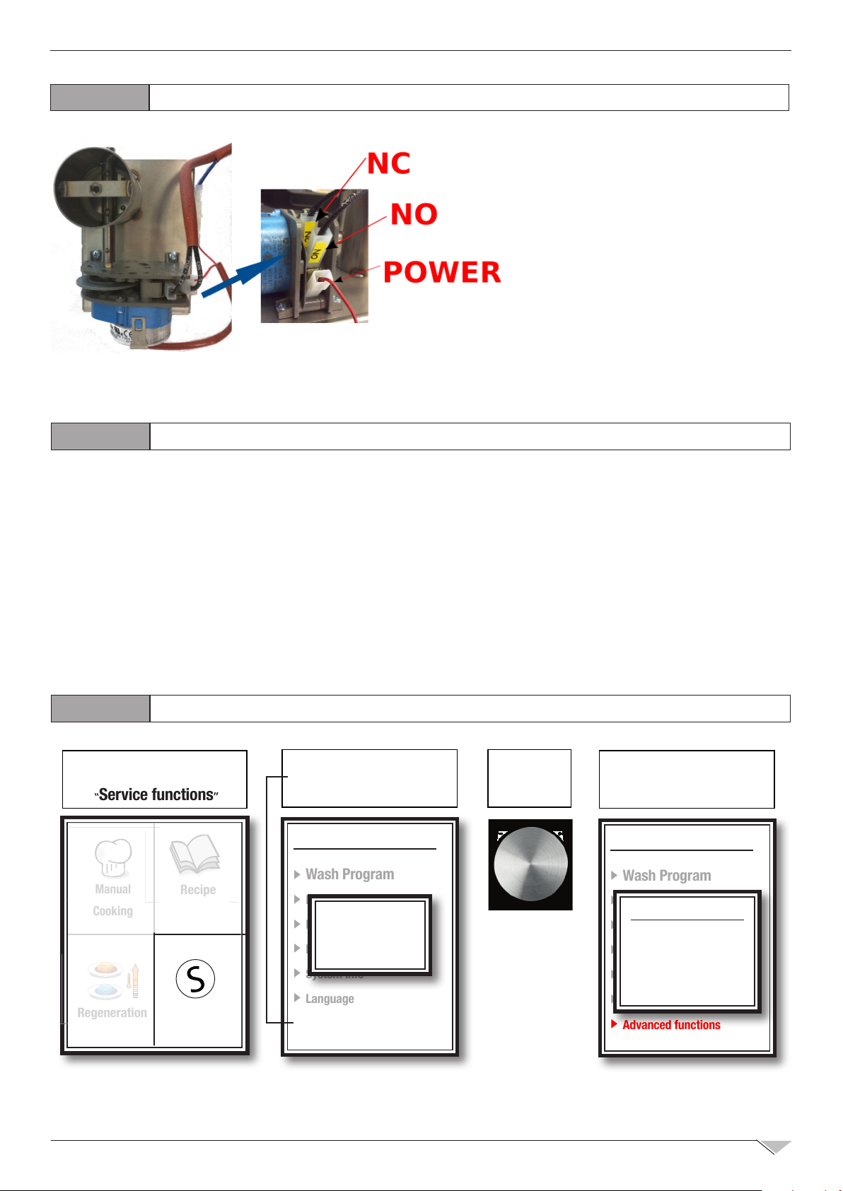
3.21
BUTTERFLY VALVE - MV
The buttery valve open or
close the air inlet to regulate the
humidity in the cavity.
It’s normally closed when the
oven is switch on in STOP mode.
To correct CLOSE position is
showed in the picture.
4.0
GAS OVEN SETUP
The oven is originally calibrated for functioning with the gas type specied during ordering.
The type of gas for which the oven is adjusted is reported on the technical place on the
appliance.
During testing, ascertain the factory calibrations carried out on the burners are appropriate for
the specic installation type, by means of analysis of the gases produced by combustion (CO2
and CO) and check of the thermal capacity.
The detected data must be recorded and become integrating part of the technical documentation
of that appliance.
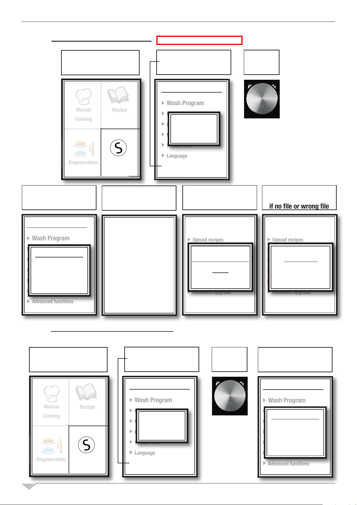
4.1
STEP 1 : SELECT
“
Service
“
Service functions
Cottura manuale
Manual
Cooking
Rigenerazione
Regeneration
COMBUSTION ANALISYS
STEP 2 : SELECT
“
” TO OPEN:
Recipe
Ricette
Service
”
Advanced functions
INSERT PASSWORD ‘156’
Service functions
Wash Program
Descaling
Password
Date and Time
156
Parameters
System info
Language
Advanced functions
” AND
STEP 3 :
PRESS KNOB
TO CONFIRM
STEP 4 :
SELECT
“
Gas test
”
Service functions
Wash Program
Descaling
Test service
Date and Time
Gas test
Parameters
I/O Check
System info
Log & USB
Language
Advanced functions
Page 16
16
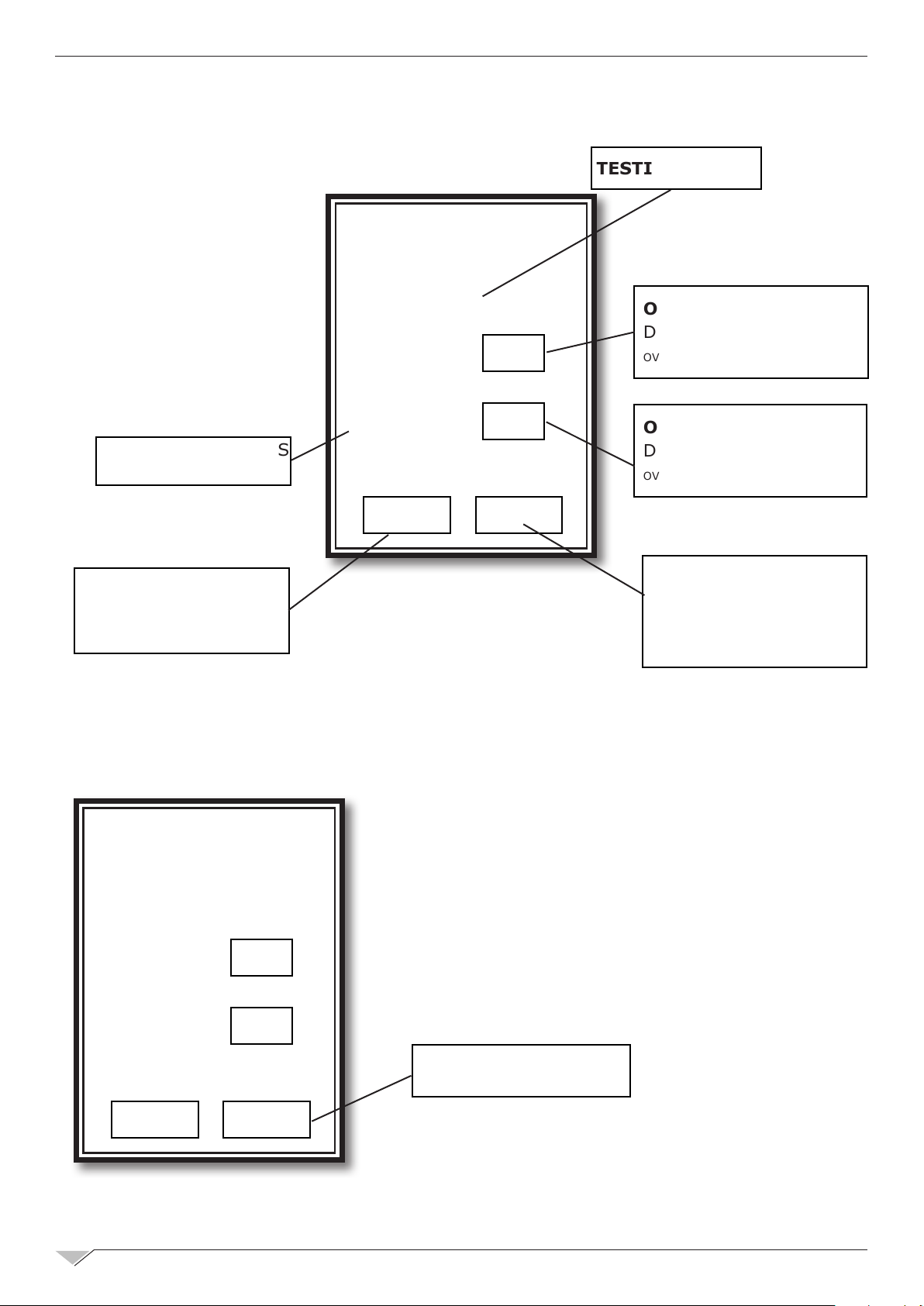
1. The gas test must be carried out with the door open.
TECHNICAL TRAINING COURSE
Gas test
Testing stage:
Please open the door
Burner 1
ON
TESTING PHASE
ON/OFF: ENABLE OR
DISABLE BURNER 1
OVENS 20 GN 1/1 e 2/1 ONLY
20 RACK CAP. OVENS
ONLY
PRESS TO RETURN TO
THE PREVIOUS “STATE”
2. Starting gas test procedure:
After opening the oven door the testing procedure can be started by pressing the “NEXT”key.
Gas test
Burner 2
OFF
Back Next
ON/OFF: ENABLE OR
DISABLE BURNER 2
OVENS 20 GN 1/1 e 2/1 ONLY
FORWARD/START:
START THE TEST OR
GOES TO THE NEXT
PHASE
Testing stage:
Ready to start
Burner 1
Burner 2
ON
OFF
Back Next
GAS TEST START KEY
Page 17
TECHNICAL TRAINING COURSE
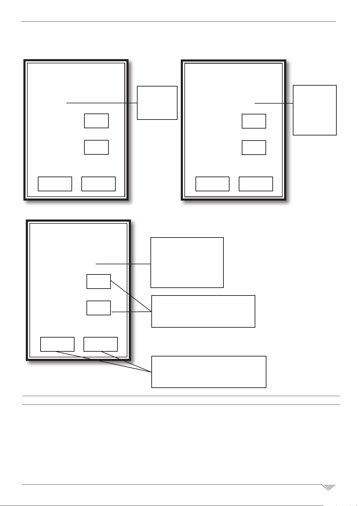
3. Adjustment of burners to minimum and maximum power:
17
Gas test
Testing stage:
Firing
Burner 1
Burner 2
ON
OFF
Back Next
Gas test
Testing stage:
Maximum speed
Burner 1
ON
Gas test
STATE:
BURNER
IGNITION
STATE:
BURNER/S
AT
MAXIMUM POWER
Testing stage:
Minimum speed
Burner 1
Burner 2
ON
OFF
Back Next
STATE:
BURNER/S
AT
MINIMUM
POWER
Burner 2
OFF
PRESS ON/OFF TO SWITCH
ON OR OFF THE CORRESPONDING BURNER (1 OR 2)
Back Next
PRESS BACK NEXT TO MOVE
FROM MINIMUM TO MAXIMUM
POWER AND VICE-VERSA
To end the GAS test procedure press NEXT until exiting the main menu screen
Page 18
18
TECHNICAL TRAINING COURSE
4.2
GAS REFERENCE TABLE
ADJUSTEMENT COMBUSTION VALUES #
OVEN
MODEL
6 GN
1/1
6 GN
2/1
10 GN
1/1
10 GN
2/1
TYPE OF GAS
TYPE OF
GAS
NATURAL G20 43 44 8 12 9,5 % 9,2 %
LPG
NATURAL G20 43 44
LPG
NATURAL G20 44 45 13 19 9,8% 9,4%
LPG
NATURAL G20 44
LPG
TO MAKE
REFERENCE
FOR THERMAL
CAPACIT
G30
G31
G30
G31
G30
G31
G30
G31
NOZZLE
1/10 mm
35 34 - 36 8,5 12
35 34 - 36
35 34 - 36 13,5 19
35
ALTERNA-
TIVE
NOZZLES
45 22 27
34 - 36 22 27
POWER
MAX
16,5 20 9,6 % 9,6 %
16,5 20
POWER
MAX
REFERENCE
11%-11,8%
G31 - G30
11,2%-11,5%
G31 - G30
11,5%-11,8%
G31 - G30
11,4%-11,7%
G31 - G30
CO2
MIN
9,8 10,2
CO2
REFERENCE
MAX
10,7 %-11,3%
G31 - G30
11,2%-11,5%
G31 - G30
10,9%-11,5%
G31 - G30
11,6%-11,9%
G30 - G31
B
U
R
N
E
R
S
1
1
1
1
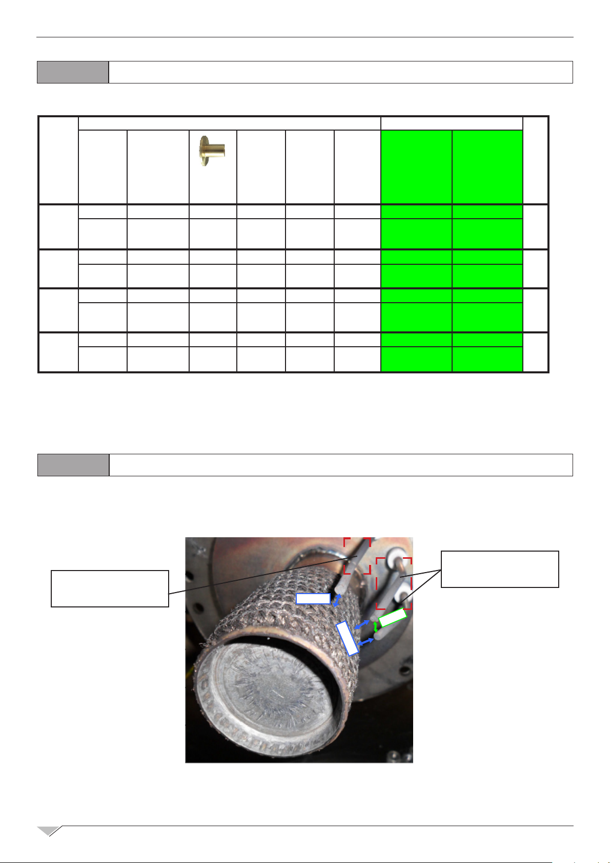
4.3
DETECTING
FLAME PROBE
SETTING IGNITION PROBES AND DETECTING FLAME PROBE
IGNITION
PROBES
5mm
5mm
3,5mm
Page 19
TECHNICAL TRAINING COURSE
Rigenerazione
Cottura manuale Rigenerazione
Service
19
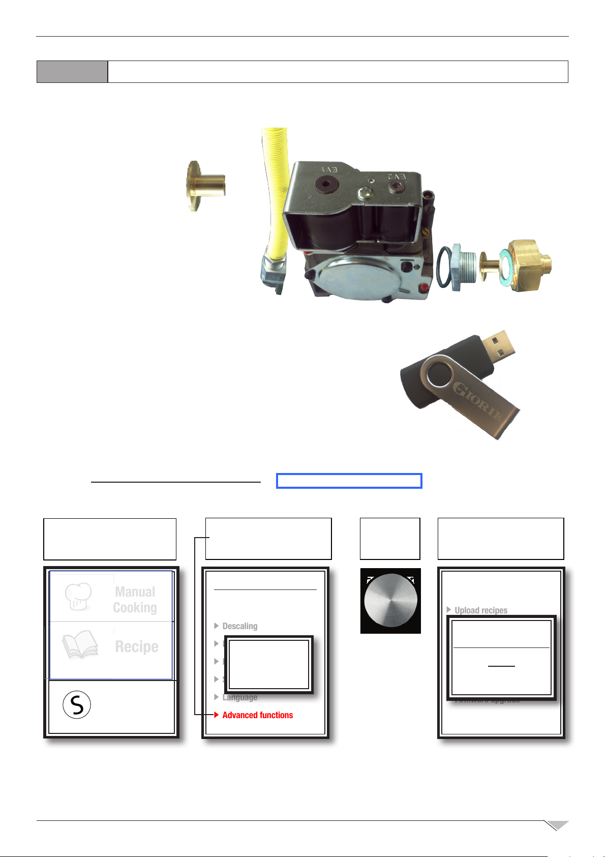
4.4
GAS CHANGE PROCEDURE
1. Replace nozzle (injector) on gas valve
2. Insert the USB drive in the oven USB port (the PARAMETERS
FILE loaded is specic for each oven model and gas
setting: FILE “PARXXX.CSV).
3.1.a UPLOAD GAS PARAMETERS
STEP 1 : SELECT
“
Service
” TO OPEN:
“
Service functions
”
STEP 2 : SELECT
“
Advanced functions
INSERT PASSWORD ‘114’
Service functions
Manual
ttura manuale
Ricette
Cooking
Recipe
Service
Wash Program
Descaling
Date and Time
Password
Parameters
114
System info
Language
Advanced functions
Ver 250 : OLD BOARD
STEP 3 :
” AND
PRESS KNOB
TO CONFIRM
A pop-up stating that
the transfer is complete
appears
Log & USB
Upload recipes
Download recipes
USB UPDATE
Download HACCP log
Download parameters
Upload parameters
OK
Firmware upgrade
OK!
Page 20
20
Rigenerazione
Cottura manuale Rigenerazione
Service
Rigenerazione
Cottura manuale Rigenerazione
Service
TECHNICAL TRAINING COURSE
3.1.b UPLOAD GAS PARAMETERS
STEP 1 : SELECT
“
Service
” TO OPEN:
“
STEP 4 :
SELECT
“
Log & USB
Service functions
Cottura manuale
Manual
Cooking
Rigenerazione
Regeneration
”
Recipe
Service
”
Ricette
STEP 5 :
SELECT
“
Upload parameters
Ver 344 : NEW BOARD
STEP 2 : SELECT
“
Advanced functions
INSERT PASSWORD ‘156’
” AND
Service functions
Wash Program
Descaling
Password
Date and Time
156
Parameters
System info
Language
Advanced functions
A pop-up stating that
the transfer is complete
”
appears
STEP 3 :
PRESS KNOB
TO CONFIRM
ERROR
pop-up appears
if no le or wrong le
Service functions
Wash Program
Descaling
Test service
Date and Time
Gas test
Parameters
I/O Check
System info
Log & USB
Language
Advanced functions
Log & USB
Upload recipes
Download recipes
Download HACCP log
Download parameters
Upload parameters
Firmware upgrade
4.1 ACTIVATE GAS TEST PROCEDURE
STEP 1 : SELECT
“
Service
” TO OPEN:
“
Service functions
”
STEP 2 : SELECT
“
Advanced functions
INSERT PASSWORD ‘156’
Service functions
Log & USB
Upload recipes
Download recipes
USB UPDATE
Download HACCP log
Download parameters
Upload parameters
OK
Firmware upgrade
” AND
OK!
STEP 3 :
PRESS KNOB
TO CONFIRM
Log & USB
Upload recipes
Download recipes
ERROR!
Download HACCP log
Download parameters
Upload parameters
OK
Firmware upgrade
STEP 4 :
SELECT
“
Gas test
”
Service functions
Cottura manuale
Manual
Cooking
Rigenerazione
Regeneration
Recipe
Service
Ricette
Wash Program
Descaling
Password
Date and Time
156
Parameters
System info
Language
Advanced functions
Wash Program
Descaling
Test service
Date and Time
Gas test
Parameters
I/O Check
System info
Log & USB
Language
Advanced functions
Page 21
TECHNICAL TRAINING COURSE
5. Check the combustion and, if
necessary, change the nozzle.
21
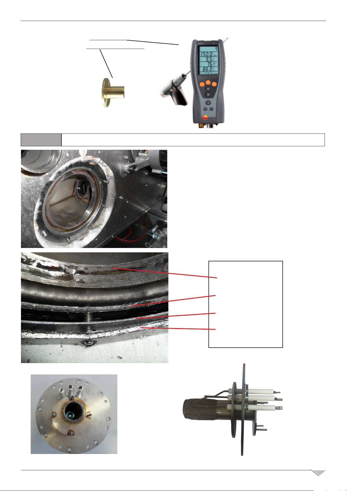
4.5.1
FIXING THE BURNER TO THE EXCHANGER: GASKET SEQUENCE
EXCHANGER
GRAPHITE GASKET
OVEN CHAMBER
GRAPHITE GASKET
Page 22
22
TECHNICAL TRAINING COURSE
4.5.2
FIXING THE BURNER TO THE EXCHANGER: NOTES
SPECIAL GREASE
SELF BLOCKING NUT M6
WASHER
Page 23

TECHNICAL TRAINING COURSE
23
NUTS M6 MUST BE
CLOSED BY USING
A TORQUE WRENCH
5.0
SET TORQUE AT
6 N/m
ELECTRONIC BOARDS AND CONFIGURATION
TOUCH BOARD
MAIN POWER BOARD
EXPANSION CARD
Page 24

24
TECHNICAL TRAINING COURSE
5.1
RULES OF SERIAL CONNECTION
KEYBOARD
BOARD
CONFIGURATION OF ELECTRONIC BOARDS SERIAL CONNECTION
“A” BOARD
“B” BOARD
1. All electronic boards of the SteamBox ovens
‘component panel’ area communicate with the
keyboard motherboard (touch or programmable)
via RS485 serial connection
2. ‘Keyboard’ board is the main board and the
operation conguration of other boards connected
in serial depends on it.
3. The beginning and the end of the serial connection
must always be completed by means of dip-
switch activation
4. In case that more than one board of the same
type are present in the system, these must be
addressed in a different way, by using another
dip-switch
485 SERIAL CONNECTION
Keyboard board is always at the BEGINNING of the
serial connection and so they must be completed by
activating the corresponding DIP-SWITCH in ON
The type of serial connection termination must be
start:ON –OFF – OFF ……OFF – ON:end. Therefore,
the board at the end of the serial connection ‘chain’
must be completed.
Page 25

TECHNICAL TRAINING COURSE
25
PWM “8” BOARD TERMINATOR
Switch ON
if it is the
end of the
serial line
INVERTER BOARD TERMINATOR
Switch ON
if it is the
end of the
serial line
Address in different way in case there are more than one board of the same type:
PWM “6” BOARD ADDRESS
INVERTER BOARD ADDRESS
Switch ON
if it is the 2nd
board of the
serial line of
this type
Switch ON
if it is the 2nd
board of the
serial line of
this type
Page 26

26
Rigenerazione
Cottura manuale Rigenerazione
Service
TECHNICAL TRAINING COURSE
5.2
STEP 1 : SELECT
“
Service
” TO OPEN:
“
Service functions
Cottura manuale
Manual
Cooking
Rigenerazione
Regeneration
5.2.1
I/O CHECK
“
Advanced functions
”
INSERT PASSWORD ‘156’
Service functions
Wash Program
Recipe
Ricette
Service
Descaling
Date and Time
Parameters
System info
Language
Advanced functions
I/O CHECK - PROBES
STEP 2 : SELECT
Password
156
” AND
STEP 3 :
PRESS KNOB
TO CONFIRM
STEP 4 :
SELECT
“
I/O Check
”
Service functions
Wash Program
Descaling
Test service
Date and Time
Gas test
Parameters
I/O Check
System info
Log & USB
Language
Advanced functions
Identication Probe Clamp
S1 – probe 1
NTC on board - power card temperature (ALARM: Hi-
Temp)
---
S2 – probe 2 // //
S3 – probe 3 CORE thermocouple J 14 – 15
S4 – probe 4 FREE 12 – 13
S5 – probe 5 cavity thermocouple J 10 – 11
S6 – probe 6 FREE 20 – 21
S7 – probe 7 Humidity probe 2 thermocouple J (ALARM: PROBE 5) 18 – 19
S8 – probe 8 Humidity probe thermocouple J (ALARM : PROBE 4 ) 16 – 17
S9 – probe 9 // //
S10 – probe 10 // //
S11 – probe 11 // //
S12 – probe 12 // //
Page 27

TECHNICAL TRAINING COURSE
27
5.2.2
Identication Input Clamp
I1 – Motor safety 1
I2 – Motor safety 2
(2 motors ovens only)
I3 – Safety
thermost
I4 – Alarm burner 1 Burner 1 block (230Vac) 36 – 37
I5 – Alarm burner 2 Burner 2 block (230Vac) 35 – 37
I7 – Door switch
I8 – Air safety 1
I9 – Air safety 2
I10 – Boiler level
I/O CHECK - DIGITAL INPUTS
Motor 1 thermal protection (230Vac)
0= open/faulty
1= close/active
Motor 2 thermal protection (230Vac)
0= open/faulty
1= close/active
Chamber safety (230Vac) 38 – 41
Door input
1 = door open
0 = door closed
Air ow inlet 1
1 = contact open
0 = close if vacuum
Air ow inlet 2
1 = contact open
0 = close if vacuum
Level 1 input
1 = boiler empty
0 = boiler full
40 – 41
39 – 41
6 – 9
7 – 9
8 – 9
44 – 45
I11 – L2 not used 43 – 45
I12 – L3 not used 42 – 45
I13 not used 60 – 61
example: BOILER TEST
1) Make sure that boiler is empty verifying I10 = 1 or activate R17 for almost 15 seconds to drain water
from the boiler
2) Activate R18 to load boiler water
3) Check I10: in almost 60 second boiler level will change to ---> =0 boiler full. Boiler level must be ‘0’
and has not to change itself, otherwise there is a leakage into boiler or solenoid valve.
If the level does not change please verify water loading system (water inlet , lime,obstructions..etc ) and
check the functionality of level control system (probe cleaning, control board ‘ok’)
4) Activate R20 and verify Amperage with a clamp meter (boiler 6/10 gn1/1, 6 gn2/1 = 4,3A ; boiler 20
gn1/1, 10/20 gn2/1 = 10.8A)
Page 28

28
TECHNICAL TRAINING COURSE
5.2.3
I/O CHECK - DIGITAL OUTPUTS
In this section one can pilot some utilities manually by positioning the cursor on the desired
utility and pressing the encoder key. By pressing the encoder key again the utility is deactivated.
Identication Relay Notes Clamp
R1:
Resist 1
R2:
Resist 1+2
R4:
Humidity disch.
Chamber 1
Chamber 2
Buttery valve
Electric oven actionable only remains active for max. 10s. The fan
is activated as well.
Electric oven actionable only remains
active for max. 10s. The fan is activated as well.
Commands opening and closing.
Command active only with discharge
stopped. Positioning change occurred
display.
33 – 34
32 – 34
29 – 31
door open : active
R5:
Hand shower
Shower
electrovalve
door closed : inactive
(to protect hand shower hose from
28 - 31
over pressure)
R9:
Steam kill
R10:
Humidif
R11:
Discharge
R12:
Washing water
R13:
Washing pump
R17:
Boiler discharg
R18:
Boiler water
R19:
Detergent
R20:
Boiler resist.
Quencing
electrovalve
23 – 26
Humidier 22 – 26
Chamber
discharge
46–47–50
motorised valve
Load solenoid
valve
48 – 50
washing water
Washing pump 49 – 50
Boiler Discharge
solenoid valve
Boiler Load
solenoid valve
Pump
Detergent load
Boiler
resistances
0.85 oz/sec (0.025 liter/sec)
54 – 57
55 – 57
56 – 57
58 – 59
H1:
Pulse counter
600 Pulses = 2.1 pt lqd
(1liter)
Washing water
liter counter
Increases its value if water from the
R12 solenoid valve is loaded
JST – J5
Page 29

TECHNICAL TRAINING COURSE
29
5.3
• After the number of minutes since the last recording, as set in the
parameter.
• In cooking mode with core probe: when the core temperature since the last re-
cording differs by the number of degrees set in the parameter
• In "timed" cooking when the chamber temperature since the last recording differs
by the number of degrees set in the parameter
• When the oven stops or at the end of the cooking program.
5.3.1
The printout data are logged in a different le for each day. All of the cooking cycles performed in the same day (taking into consideration the start time) are saved progressively in
the same le. The name of the le will be "yy_mm_dd.log where yy = year, mm = month and
dd = day. The le is in text format.
HACCP RECORDING (TOUCH BOARD)
If printouts are enabled through the
"start" is pressed on the oven, it begins recording the cooking.
The cooking data are: time, chamber temperature and, if present, core probe temperature. Recording is done at the follow-
ing times:
• At start. At automatic pre-heating as indicated.
• Switching from pre-heating to cooking (when the door is
opened and closed at the end of pre-heating).
• At every phase change.
DeltaTHACCP
COOKING LOG MEMORISATION
EnHACCP
DeltaTHACCP
.
parameter when
TimeStHACCP
.
5.3.2
**************************************** Separator
Start Log 10/09/2010 15:23 Start
Roast Program name
Core Chamber Time Column Name
Phase 1 Phase no.
15:23:32 084 --- Date
15:23:35 084 ---
End Log End
5.3.3
P500 - HACCP enabling:
0 = disabled (default)
1 = enabled only for probe cooking (WITH USB pen-drive connected)
2 = enabled for all cooking (WITH USB pen-drive connected)
ONLY:
Ver 344 : NEW BOARD
PRINTOUT EXAMPLE
HACCP PARAMETERS
3 = enabled only for probe cooking (WITHOUT USB pen-drive connected,download after)
4 = enabled for all cooking (WITHOUT USB pen-drive connected,download after)
P501 = Maximum time between HACCP data (1-20 minutes): default ‘5’
P502 = Maximum temperature difference (at core if cooking with probe or chamber if
timed cooking between HACCP data saves (1-20° C): default ‘5’
Page 30

30
Rigenerazione
Cottura manuale Rigenerazione
Service
Rigenerazione
Cottura manuale Rigenerazione
Service
TECHNICAL TRAINING COURSE
5.3.4
STEP 1 :
INSERT A EMPTY
USB PENDRIVE
DOWNLOAD HACCP LOG--->USB
STEP 2 : SELECT
“
Service
” TO OPEN:
“
Service functions
Cottura manuale
Manual
Cooking
Rigenerazione
Regeneration
Recipe
Service
Ricette
”
Service functions
Date and Time
Parameters
System info
Language
Advanced functions
Wash log - Download
USB
STEP 3 :
SELECT
“
USB
”
Ver 344 : NEW BOARD
STEP 4 :
SELECT
“
Download log HACCP”
USB
Download log HACCP
Upload recipes
Download recipes
Firmware upgrade
USB
5.4
STEP 1 :
INSERT A EMPTY
USB PENDRIVE
A pop-up stating that
the transfer is complete
appears
WASH LOG - DOWNLOAD - ERASE
STEP 2 : SELECT
“
Service
” TO OPEN:
“
“
Service functions
Cottura manuale
Manual
Cooking
Rigenerazione
Regeneration
Recipe
Ricette
Service
”
Wash log - Download
Service functions
Date and Time
Parameters
System info
Language
Advanced functions
Wash log - Download
USB
STEP 3 :
SELECT
Upload recipes
Download recipes
USB UPDATE
Download HACCP log
OK!
Ver 344 : NEW BOARD
”
Wash log
Soft - 18/07/14 - 11:11
Hard - 20/07/14 - 19:15
AVAILABLE ONLY IF THE
PASSWORD ‘156’
WAS INSERTED BEFORE
Wash log
USB UPDATE
OK!
Wash log
Soft - 18/07/14 - 11:11
Hard - 20/07/14 - 19:15
Erase LOG?
Yes No
Page 31

TECHNICAL TRAINING COURSE
Rigenerazione
Cottura manuale Rigenerazione
Service
Co
Rigenerazione
Cottura manuale Rigenerazione
Service
31
5.5
5.5.1
STEP 1 : INSERT
USB PENDRIVE WITH
RECIPES FILE
“GRECIPE.CSV”
UPLOAD - DOWNLOAD RECIPES
UPLOAD RECIPES
STEP 2 : SELECT
“
Service
” TO OPEN:
“
Service functions
Cottura manuale
Manual
Cooking
Rigenerazione
Regeneration
Recipe
Ricette
Service
STEP 3 :
SELECT
”
“
USB
”
Service functions
Date and Time
Parameters
System info
Language
Advanced functions
Wash log - Download
USB
Download log HACCP
Upload recipes
Download recipes
Firmware upgrade
STEP 4 :
SELECT
“
Upload recipes”
USB
5.5.2
STEP 1 :
INSERT A EMPTY
USB PENDRIVE
DOWNLOAD RECIPES
STEP 2 : SELECT
“
Service
” TO OPEN:
“
Service functions
ttura manuale
Manual
Cooking
Rigenerazione
Regeneration
Recipe
Service
”
Ricette
USB
ERROR!
OK
ERROR
pop-up appears
if no le or wrong le
STEP 3 :
SELECT
“
USB
”
Service functions
Date and Time
Parameters
System info
Language
Advanced functions
Wash log - Download
USB
USB
Upload recipes
USB UPDATE
Download recipes
Download HACCP log
OK!
A pop-up stating that
the transfer is complete
appears
STEP 4 :
SELECT
“
Download recipes”
USB
Download log HACCP
Upload recipes
Download recipes
Firmware upgrade
USB UPDATE
OK!
Page 32

32
Co
Rigenerazione
Cottura manuale Rigenerazione
Service
TECHNICAL TRAINING COURSE
5.6
WASH LOG - DOWNLOAD/ERASE
STEP 1 : INSERT
A EMPTY USB
PENDRIVE
STEP 5 :
SELECT
“
Log & USB
“
ttura manuale
Cooking
Rigenerazione
Regeneration
”
STEP 2 : SELECT
“
Service
” TO OPEN:
Service functions
Manual
Recipe
Ricette
Service
STEP 6 :
SELECT
“
Wash log - Download”
Ver 344 : NEW BOARD
STEP 3 : SELECT
“
Advanced functions
”
INSERT PASSWORD ‘156’
” AND
STEP 4 :
PRESS KNOB
TO CONFIRM
Service functions
Wash Program
Descaling
Password
Date and Time
156
Parameters
System info
Language
Advanced functions
“
Wash log - Download”
STEP 7 :
SELECT
Service functions
Wash Program
Descaling
Test service
Date and Time
Gas test
Parameters
I/O Check
System info
Log & USB
Language
Advanced functions
Log & USB
HACCP log - Download
Wash log - Download
Alarm log - Download
Upload recipes
Download recipes
Upload parameters
USB
Upload recipes
USB UPDATE
Download recipes
Download HACCP log
A pop-up stating that
the transfer is complete
OK!
appears
Wash log
Soft - 18/07/14 - 11:11
Hard - 20/07/14 - 19:15
Wash log
Soft - 18/07/14 - 11:11
Hard - 20/07/14 - 19:15
Erase LOG?
Yes No
STEP 8 :
SELECT AND CONFIRM
PRESSING KNOB
Page 33

TECHNICAL TRAINING COURSE
33
5.7
ALARMS DESCRIPTION
In case of alarm the identifying name of the alarm in progress appears on temperature display and on time display. The following alarms are managed:
Name Description Actions SOLUTION
Chamber
probe
Core
probe
GAS Gas burner block Cooking block, manual restore.
GAS 2 Gas second burner block. Cooking block, manual restore.
Motor
safety
Inverter
code:
Chamber
safety
PWM
PWM 2
Air Flow
Air
Flow 2
Hi temp
No water
Chamber probe error
Core probe error Manual restore. Replace core probe.
Motor Alarm Cooking block, automatic re-arm
Motor Inverter Alarm Cooking block, automatic re-arm
Chamber safety thermal. Cooking block, manual re-arm.
PWM board error
(communication timeout
or problems on fan speed)
PWM second board error
(communication timeout
or problems on fan speed)
Air capacity on gas
burner alarm
Air capacity on second
gas burner alarm
Technical compartment
temperature too high.
No water for the
production of steam.
Cooking block, automatic
restore.
Cooking block.
Cooking block.
Cooking block, manual restore.
Cooking block, manual restore.
Cooking is blocked, automatic
restore.
Cooking is blocked, automatic
restore.
Replace chamber probe.
Press manual restore.
(encoder button for 1 Second)
Press manual restore.
(encoder button for 1 Second)
If continuous, contact after-sales
assistance.
Check the inverter error table at
page 36.
Check the safety thermostat (par.
3.8 page 12).
Check 24 volt power supply,pwm,
connection cables and fan blower
Check 24 volt power supply,pwm,
connection cables and fan blower
Check obstructions to combu-
stion fumes exhaust ue, check
pressostat at the and of the gas
blower.
Check obstructions to combustion
fumes exhaust ue, otherwise
contact after-sales assistance.
Check oven's perimeter ventilation,
the lower air lter (pag. 46) and the
correct functioning of the cooling fans
of the components.
Check connection to water duct, the
boiler and water presostat. Check
opening of the shut-off cook.
No water
owmeter
Com
PWM
Com
PWM2
Communication
No drain Boiler water did not drain
Power fail Electrical power failure Cooking block. Press encoder button for 1 Second.
Probe 4 Humidity control probe 4
Probe 5 Humidity control probe 5
Washing owmeter alarm Washing is blocked.
PWM board
communication error
PWM2 board
communication error
Main board
communication error
correctly
alarm
alarm
Cooking block.
Cooking block. Check cleaness of the lower fan
Cooking block. Remove power and then give back.
Cooking block. Remove power and then give back.
Cooking block. Replace humidity probe 4
Cooking block. Replace humidity probe 5
Check connection to water duct and
opening of the shut-off cook Check
the owmeter.
Check cleaness of the upper fan
blower and fan power connection.
Remove power and give back.
blower and fan power connection.
Remove power and give back.
If continuous, contact after-sales
assistance.
Check cleaness and operation of
the boiler diascharge valve.Check
te boiler.
Page 34

34
Rigenerazione
Cottura manuale Rigenerazione
Service
TECHNICAL TRAINING COURSE
5.8
ALARM LOG - DOWNLOAD/ERASE
STEP 1 : INSERT
A EMPTY USB
PENDRIVE
STEP 5 :
SELECT
“
Log & USB
STEP 2 : SELECT
“
Service
“
Service functions
Cottura manuale
Manual
Cooking
Rigenerazione
Regeneration
”
” TO OPEN:
”
Recipe
Ricette
Service
STEP 6 :
SELECT
“
Wash log - Download”
Ver 344 : NEW BOARD
STEP 3 : SELECT
“
Advanced functions
INSERT PASSWORD ‘156’
Service functions
Wash Program
Descaling
Password
Date and Time
156
Parameters
System info
Language
Advanced functions
“
Alarm log - Download”
” AND
STEP 7 :
SELECT
STEP 4 :
PRESS KNOB
TO CONFIRM
Service functions
Wash Program
Descaling
Test service
Date and Time
Gas test
Parameters
I/O Check
System info
Log & USB
Language
Advanced functions
Log & USB
HACCP log - Download
Wash log - Download
Alarm log - Download
Upload recipes
Download recipes
Upload parameters
USB
Upload recipes
USB UPDATE
Download recipes
Download HACCP log
A pop-up stating that
the transfer is complete
OK!
appears
Alarm log
18/07/14 11:11
E03 Inverter code: 08
20/07/14 08:13
E16 Comunication
Alarm log
18/07/14 11:11
E03 Inverter code: 08
Erase LOG?
Yes No
STEP 8 :
SELECT AND CONFIRM
PRESSING KNOB
Page 35

TECHNICAL TRAINING COURSE
35
5.9
5.10
SYSTEM INFO MENÙ
System info
Keyboard:
Ver 344 Rev 001d
RevE2 000
08/07/14
Base:
Ver 240 Rev 003
02/08/10
SR.N. 001234/05/14
Boiler: 23hr
INVERTER ALARM SIGNAL DIAGNOSTIC
A page appears showing:
Keyboard rmware version:
Base rmware version.
Ver 344 : NEW BOARD
Ver 250 : OLD BOARD
The oven serial number and the boiler operating hours
(after the last discaling) are also given.
If the advanced services menu has been previously
accessed by introducing the line end inspection
password “956”, by pressing the touch screen, access
the oven serial number setting menu, otherwise go
back to the service menu.
In case the oven main board signals an INVERTER
alarm (or 1nv on programmable version) can open the
panel compartment to detect the number of ‘ashes’
indicated by the RED LED
(code error appear on display)
The type of ashes sequence is: 1.5s pause followed
by 0.5s ash 0,5s pause.
ERROR CODIFICATION (code number = number
of ashes):
code 1: Error inside the Inverter. Disconnect the power supply of the oven and power it
again, if the inverter must be replaced.
code 2: Failure on the motor (short), overcharged, or blocked motor. Perhaps the motor has
some internal problems or something has blocked it.
code 3: The dissipator temperature of the inverter is too high: verify the ventilation of the
technical compartment.
code 4: Error inside the Inverter. Disconnect the power supply of the oven and power it again,
if the inverter must be replaced.
code 5: Inverter parameterization error. Disconnect the power supply of the oven and power
it again, if the inverter must be replaced.
code 6: The motor is overcharged or blocked: ensure if it can be rotated in vain.
code 7: The motor presents little connection with the burnt or removed inverter. A failure
could have occurred inside the winding
code 8 : Inverter communication error: verify the serial connection and RS485 connection
conguration (also verify the inverter power supply : green led ON)
Page 36

36
Co
Rigenerazione
Cottura manuale Rigenerazione
Service
TECHNICAL TRAINING COURSE
5.11
STEP 1 : SELECT
“
Service
“
Service functions
ttura manuale
Manual
Cooking
Rigenerazione
Regeneration
TECHNICAL PARAMETERS
” TO OPEN:
“
Parameters
Service functions
Wash Program
Descaling
Date and Time
Parameters
System info
Language
Advanced functions
Recipe
Ricette
Service
”
STEP 2 :
SELECT
STEP 3 :
INSERT
”
PASSWORD ‘156’
Service functions
Wash Program
Descaling
Password
Date and Time
156
Parameters
System info
Language
Advanced functions
P5 = Activation time cooking chamber lighting (0 – 255 seconds):
- default ‘45’. 254 = light ON during cooking
STEP 4 :
PRESS KNOB
TO CONFIRM
P14 = External buzzer activation:
0 = deactivated (the buzzer on the keyboard works, in this case the external buzzer MUST
be removed physically)
1-2 = activated
P15 = Screen saver:
0 = screen saver deactivated
1-120 = delay time to activate (seconds)
121 - 240 = delay time to activate (0-120 seconds) but the touch screen shows the total
remaing time to nish cooking cycle
P18 = Date Type:
0 = EU date
1 = US date
P70 = Steam condensation enabling (Quencing):
0 = deactivated
1 = activated (default)
P75 = Condensation activation time ( 0 – 10 ) : default ‘6’ (=60%)
0% - 100% (0-10)
P400 = Boiler descaling product reaction time ( 0 – 600 minutes ) : default is ‘360’.
The default time is set for vinegar. If other faster descaling products are used you can, for
example, decrease the value of this parameter.
P404 = Stand-by time for “boiler descaling” warning (0 – 2000 hours) : default ‘250’
The default time is set for softened water.(approximately 5 TH). If water hardness is greater
than 5-10 TH it is recommended to lower the value by P404. (For example: 20-25 hours for
20°f). WATER SOFTENER IS ALWAYS RECOMMENDED
Page 37

TECHNICAL TRAINING COURSE
Co
Rigenerazione
Cottura manuale Rigenerazione
Service
P500 - HACCP enabling:
0 = disabled (default)
1 = enabled only for probe cooking (WITH USB pen-drive connected)
2 = enabled for all cooking (WITH USB pen-drive connected)
37
ONLY:
Ver 344 : NEW BOARD
3 = enabled only for probe cooking (WITHOUT USB pen-drive connected,download after)
4 = enabled for all cooking (WITHOUT USB pen-drive connected,download after)
P501 = Maximum time between HACCP data (1-20 minutes): default ‘5’
P502 = Maximum temperature difference (at core if cooking with probe or chamber if
timed cooking between HACCP data saves (1-20° C): default ‘5’
P980 =DEMO Mode
0 = normal operation (oven)
1 = DEMO mode (showroom)
2 = DEMO mode (demo unit - demonstration panel)
3 = DEMO WASH mode (showroom/fair)
To change the value of a parameter:
1. Select the parameter by rotating the encoder knob.
2. Press the knob button to enter “parameter change” mode.
3. Rotate the encoder knob to change the value of the parameter.
4. Press the knob button to enter conrm the change.
5. Press the “esc” key to exit the “parameters” menu.
5.12
STEP 1 :
Insert USB pendrive
with les
‘V344Rxxx.MD5’ and
‘V344xxx.s19
FIRMWARE UPGRADE
STEP 2 : SELECT
“
Service
” TO OPEN:
“
Service functions
”
Service functions
Date and Time
ttura manuale
Manual
Cooking
Rigenerazione
Regeneration
Recipe
Ricette
Service
Parameters
System info
Language
Advanced functions
Wash log - Download
USB
STEP 3 :
SELECT
“
USB
”
STEP 4 :
SELECT
“
Firmware upgrade”
USB
Download log HACCP
Upload recipes
Download recipes
Firmware upgrade
WAIT UNTIL
JOB IS ENDED!
A pop-up will appear on the
screen
Upgrading procedure will be
approximately 45-60 seconds
Page 38

38
Rigenerazione
Cottura manuale Rigenerazione
Service
Rigenerazione
Cottura manuale Rigenerazione
Service
TECHNICAL TRAINING COURSE
5.13.1
STEP 1 : SELECT
“
Service
“
Service functions
ttura manuale
Ricette
5.13.2
STEP 1 :
INSERT A EMPTY
USB PENDRIVE
UPLOAD NEW PARAMETERS
STEP 2 : SELECT
“
” TO OPEN:
Advanced functions
”
INSERT PASSWORD ‘114’
” AND
Service functions
Manual
Cooking
Recipe
Service
Wash Program
Descaling
Date and Time
Password
Parameters
114
System info
Language
Advanced functions
DOWNLOAD PARAMETERS FROM THE OVEN
STEP 2 : SELECT
“
“
Service
” TO OPEN:
“
Service functions
”
Advanced functions
Ver 250 : OLD BOARD
STEP 3 :
PRESS KNOB
TO CONFIRM
Ver 250 : OLD BOARD
STEP 3 : SELECT
INSERT PASSWORD ‘12’
A pop-up stating that
the transfer is complete
appears
Log & USB
Upload recipes
Download recipes
USB UPDATE
Download HACCP log
Download parameters
Upload parameters
OK
Firmware upgrade
” AND
OK!
STEP 4 :
PRESS KNOB
TO CONFIRM
Service functions
Download recipes
STEP 5 :
SELECT
“
Download recipes”
Wash Program
Descaling
Parameters
System info
Language
Advanced functions
ttura manuale
Ricette
Manual
Cooking
Recipe
Service
STEP 6 :
PRESS KNOB
TO CONFIRM
Service functions
Wash Program
Descaling
Date and Time
Password
Parameters
System info
Language
Advanced functions
12
A pop-up stating that
the transfer is complete
appears
Service functions
Upload recipes
Download recipes
USB UPDATE
Download HACCP log
Download parameters
Upload parameters
OK
Firmware upgrade
OK!
Page 39

TECHNICAL TRAINING COURSE
Rigenerazione
Cottura manuale Rigenerazione
Service
39
5.13.3
STEP 1 :
Insert USB pendrive
with parameters le
‘parxxxx.csv’
UPLOAD NEW PARAMETERS
Touch version
STEP 2 : SELECT
“
Service
” TO OPEN:
“
Service functions
Cottura manuale
Manual
Cooking
Rigenerazione
Regeneration
Recipe
Service
”
Ricette
Ver 344 : NEW BOARD
STEP 3 : SELECT
“
Advanced functions
INSERT PASSWORD ‘156’
Service functions
Wash Program
Descaling
Password
Date and Time
156
Parameters
System info
Language
Advanced functions
” AND
STEP 4 :
PRESS KNOB
TO CONFIRM
STEP 5 :
SELECT
“
Log & USB
”
Service functions
Wash Program
Descaling
Test service
Date and Time
Gas test
Parameters
I/O Check
System info
Log & USB
Language
Advanced functions
STEP 6 :
SELECT
“
Upload parameters
Log & USB
Upload recipes
Download recipes
Download HACCP log
Download parameters
Upload parameters
Firmware upgrade
ERROR
pop-up appears
if no le or wrong le
A pop-up stating that
the transfer is complete
”
appears
Log & USB
Upload recipes
Download recipes
USB UPDATE
Download HACCP log
Download parameters
Upload parameters
OK
Firmware upgrade
OK!
ERROR!
OK
Page 40

40
Co
Rigenerazione
Cottura manuale Rigenerazione
Service
TECHNICAL TRAINING COURSE
5.13.4
Insert a EMPTY
USB pendrive
DOWNLOAD PARAMETERS FROM THE OVEN
STEP 1 :
STEP 2 : SELECT
“
Service
“
Service functions
ttura manuale
Manual
Cooking
Rigenerazione
Regeneration
” TO OPEN:
Recipe
Ricette
Service
Ver 344 : NEW BOARD
STEP 3 : SELECT
“
Advanced functions
”
INSERT PASSWORD ‘156’
” AND
STEP 4 :
PRESS KNOB
TO CONFIRM
Service functions
Wash Program
Descaling
Password
Date and Time
156
Parameters
System info
Language
Advanced functions
STEP 5 :
SELECT
“
Log & USB
”
Service functions
Wash Program
Descaling
Test service
Date and Time
Gas test
Parameters
I/O Check
System info
Log & USB
Language
Advanced functions
STEP 6 :
SELECT
“
Download parameters
Log & USB
Upload recipes
Download recipes
Download HACCP log
Download parameters
Upload parameters
Firmware upgrade
A pop-up stating that
the transfer is complete
”
appears
Log & USB
Upload recipes
Download recipes
USB UPDATE
Download HACCP log
Download parameters
Upload parameters
OK
Firmware upgrade
OK!
Page 41

TECHNICAL TRAINING COURSE
41
6.0
6.1
Boiler descaling is activated by choosing the appropriate entry from the service menu:
(Service – descaling) (insert part of the instructions manual)
At this point a sequence of pop-ups will appear that will guide the user until the end of the
procedure. The procedure consists in the following phases:
MAINTENANCE
BOILER DESCALING
1 Stand-by phase to conrm you want to carry out descaling:
Press Esc to exit and return to the service menu
2 Boiler discharge phase:
You must wait for the boiler to drain completely
3 Reactant loading phase:
As per instructions, insert the reactant in the boiler via the appropriate inlet
4 Reactant working phase:
There is an indication of how much is left to the end of the phase.
The duration of this phase depends on the value of parameter P400 with default value: 360
minutes (6 Hours).
If you wish to use a different type of reactant you can change the value of this parameter.
With the ON/OFF key you can interrupt the “stand-by with reactant” phase to go directly
to the rinsing phase. In the event of no line power, upon reactivation the timer will restart
counting from the residual time left.
Page 42

42
TECHNICAL TRAINING COURSE
5 Rinsing phase:
In this phase, after having drained the reactant, 3 rinsing cycles are carried out in this manner:
a) Water loading with discharge open for 60 seconds.
b) Water loading for 20 seconds past the level.
c) Water discharge for 10 seconds below the level.
During the rinsing phase a lack of water may be diagnosed; in this case the procedure is
suspended and the following message appears:
By pressing the encoder button the procedure restarts from phase c) and if the lack of water
persists the water missing signal returns.
6 End of procedure
To exit and return to normal operation, press on the pop-up area of the touch screen, or press
Esc or the encoder key.
Decalcication request
To prevent the boiler being ruined because the user forgets to descale, there is a warning signal
every time the oven is switched on if over P404 hours of operation of the boiler have gone by
since the last descaling (default 250 hours). The following pop-up appears that can be removed
via key conrmation or touch screen:
Page 43

TECHNICAL TRAINING COURSE
43
6.2
At the end of a working day, clean the equipment, both for hygienic reasons and to avoid
malfunctionings.
The oven must never be cleaned using direct or high pressure water jets. In the same manner,
to clean the appliance do not use pan-scrubbers, steel brushes or scrapers; it is eventually
possible to use stainless steel wool, rubbing it in the direction of the sheets satin nish.
Manual cleaning
Wait for the cooking compartment to cool down.
Remove the side tray racks.
Remove the manually removable residues and place the removable parts inside dishwashers.
To clean the cooking compartment use soapy warm water. Subsequently, all interested surfaces
must be thoroughly rinsed, being careful to ensure no detergent residues remain.
To clean the oven external parts, use a damp cloth and a non-aggressive detergent.
CLEANING OVEN CAVITY
Automatic Washing System
In ovens equipped with Automatic washing function, the above described phases happen
automatically.
With this type of ovens, to perform washing, connect the pump oat to a detergent tank and
select Washing (See the instructions manual). The 4 automatic washing levels for the touch
screen version (Hard, Intense, Normal, Soft) are selected according to the cleaning necessary
to remove the cooking residue in the compartment (Hard=deep clean, for
very resistant dirt, Soft=light wash).
Washing can be interrupted at any moment, by pressing the button Start/Stop until loading
the detergent. After loading, one must wait for the washing cycle to nish.
To perform best results in automatic whashing system is recommended to use:
BKI OVEN CLEANER AND RINSE AGENT
Technician can inTerrupT The washing cycle by pressing The knob for 10
seconds and inserT password 222
Page 44

44
TECHNICAL TRAINING COURSE
6.3
CLEANING PANEL AIR FILTER
The lter is located under the
panel.
Pull it downward to remove it,
so the two clips unhook.
Separate the lter from the l-
ter holder and
wash it with water and soap.
Then reassam-
ble the lter in
the holder and
install it under
the oven panel.
Hi temp
6.4
the oven is more or less 13-14 mm with a new gasket.
see page 33
ADJUSTMENT OF THE HINGES AND THE CLOSING PIVOT OF THE DOOR
The door hinges must be adjusted to assure maximum
seal of the oven door during its functioning. It is possible
to adjust both the upper and lower hinges.
If required, to adjust the door seal, loosen the bolt
and move the door in wanted position. Once adjusted,
fasten the bolt again.
The door’s closing pin can be adjusted in depth to
eliminate any steam emissions during cooking.
It is possible to adjust pressure applied by the door
on the gasket by tightening the pin to increase or
loosening the pin to decrease it.
Once adjusted, fasten the bolt again ensuring to have
positioned the lock closing anchoring downwards.
The standard distance between door and front part of
Page 45

TECHNICAL TRAINING COURSE
45
6.5
6.6
CHANGING DOOR LIGHTS AND GLASS CLEANING
The door glass can be cleaned externally and internally.
For this purpose, turn the stop holding the internal
glass in position clockwise and, once the glass is opened, clean it with suitable detergent. Never use abra-
sive materials. The glass must be correctly closed and
locked in position by turning the stop anti-clockwise.
To replace the bulbs remove the protective glass and
replace the defective bulb with same type (Halogen 12
Volt).
WASHING SPRINKLER CLEANING
2. push up and
1.
4. 5. clean sprinkler
turn left
3. pull down
6. push up and
turn left
6. pull down to verify
it is xed
Page 46

46
TECHNICAL TRAINING COURSE
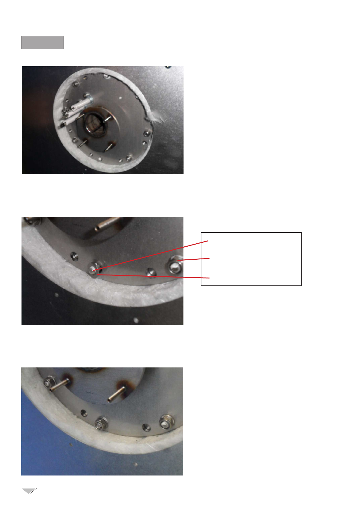
7.0
7.1
SPECIAL MAINTENANCE
BOILER OPENING AND CHECK
STEP 1:
turn the boiler bottom part to left and the upper part
to the right.
STEP 2:
Pull down the bottom part of the boiler
STEP 3:
Verify the probe status and clean the boiler with a
special product if needed.
Page 47

TECHNICAL TRAINING COURSE
47
7.2
TOOLS SET
FANS REPLACEMENT
1.
Page 48

48
TECHNICAL TRAINING COURSE
2.
5. RIGHT SCREW
3.
6. LEFT SCREW
4.
7.
8.
9.
10.
Page 49

TECHNICAL TRAINING COURSE
49
11.
14.
12.
15.
13.
16.
17.
18.
19.
Page 50

50
TECHNICAL TRAINING COURSE
20.
23.
21.
24.
22.
26.
27.
25.
28.
29.
Page 51

TECHNICAL TRAINING COURSE
51
7.3
NECESSARY: SILICONE, CUTTER AND 1 NEW GASKET
2. CAREFULLY CLEAN THE SEAT OF THE GASKET
DOOR GASKET REPLACEMENT
1. REMOVE THE OLD GASKET
3. PREPARE THE SEAT WITH SILICONE ALL ALONG THE PERIMETER, IN ALL RIVETS AND
IN THE CORNERS
4. FIX THE NEW GASKET.
FIRST ON TOP
5. THEN ON THE BOTTOM
6. PUSH THE GASKET IN
SEAT ALL ALONG THE PERIMETER
Page 52

52
7. PULL THE GASKET IN ITS
SEAT OF ABOUT 2 mm.
LOWER SIDE ONLY
TECHNICAL TRAINING COURSE
8. CAREFULLY COVER THE LOWER FESSURE WITH SILICONE
9. CAREFULLY PUSH THE
GASKET BACK IN SEAT
7.4
COMPLETE DOOR HANDLE REPLACEMENT
10. CLEAN THE EXCEEDING
SILICONE
11. WAIT 8 HOURS WITH
DOOR OPENED
TOOLS NEEDED
Page 53

TECHNICAL TRAINING COURSE
53
1.
3.
2.
4.
5.
7.
6.
8.
Page 54

54
TECHNICAL TRAINING COURSE
8.0
ELECTRICAL DRAWINGS
LEGEND
C,C1,,, Capacitor
EU,EU1,EU2 Electrovalve for humidier
EA Steam kill solenoid valve
EL Washing electrovalve
ES Boiler discharge electrovalve
ESH Hand shower electrovalve
EV Boiler load electrovalve
EVG Gas solenoid valve
FM1,FM2 Motor thermic protection (incor.)
FU1,FU2… Fuse
FLC Filter E.M.C.
FR1,FR2… Cooling fan
FS1 Chamber safety thermostat
FS2 Bolier safety thermostat
IGN,IGN1,IGN2 Burner control
INV,INV1,INV2 Motor inverter
K0 Inverter line relay
KØA,KØB Auxiliary power line contactor
Keyboard Keyboard electronic card
KR1/3,…. Chamber resistance contactor
L1, L2 Chamber lighting lamp
M1, M2.. Motor
MB1,MB2.. Gas Blower
MS Discharge valve motorized
MV Humidity discharge valve
P1,P2.. Burner air pressure switch
PA Water pressure switch
PB Rinsing agent pump
PFC PFC
PD Detergent pump
PL Washing pump
PWM Gas blower speed control board
R1,R2…. Resistance
S0 Main switch
SC Chamber probe
SCHF Oven control electronic card
SP Door microswitch
SS Core Probe
SU1, SU2 Umidity probe
TR1 Trasformer 230V/12V, 12VA - 5VA
TR2,TR3 Trasformer 230V/24V AC
TRAL Chamber light trasformer 230V/12V AC
X./.. Power plug
Z1 Boiler level control probe
Page 55

TECHNICAL TRAINING COURSE
55
Page 56

56
TECHNICAL TRAINING COURSE
Page 57

TECHNICAL TRAINING COURSE
57
Page 58

58
TECHNICAL TRAINING COURSE
Page 59

TECHNICAL TRAINING COURSE
59
Page 60

60
TECHNICAL TRAINING COURSE
Page 61

TECHNICAL TRAINING COURSE
61
Page 62

62
ABTE062R
Rev. 00
Pg. 1/3
7
2
20
31
30
26
9
25
24
10
11
15
14
4
Pg.3
Pg.2
5
6
8
29
28
27
13
Pg.2
16
18
17
19
1
TECHNICAL TRAINING COURSE
9.0
SPARE PARTS EXPLODED VIEW
Page 63

TECHNICAL TRAINING COURSE
2
20
27
3
4
5
Pg 2
Pg 2
Pg. 3
6
8
13
14
22
15
29
19
21
23
28
31
30
1
SBHE061W
Rev. 02
Pg. 1/3
7
16
17
18
11
12
10
9
24
25
63
Page 64

64
ABTE062R
Rev. 00
Pg. 3/3
50
51
64
56
52
53
54
55
57
58
60
59
61
62
62
63
TECHNICAL TRAINING COURSE
Page 65

TECHNICAL TRAINING COURSE
ABTE062R
Rev. 00
Pg. 2/3
46
39
40
41
42
43
44
43
45
47
48
32 33 34 35 36
37
38
65
Page 66

66
26
18
19
23
24 25
ABTG062R
Rev. 00
Pg. 1/3
2
1
6
34
35
17
4
Pg.2
5
27
Pg.2
7
8
13
15
16
20
14
22
21
Pg.3
18
31
9
32
11
10
33
37
38
TECHNICAL TRAINING COURSE
Page 67

ABTG062R
Rev. 00
Pg. 3/3
57
58
59
60
61
62
66
67
68
69
71
27
27
64
63
65
70
TECHNICAL TRAINING COURSE
67
Page 68

68
ABTG062R
Rev. 00
Pg. 2/3
53
46
47
48
49
50
51
50
52
54
55
39 40 41 42 43
4445
TECHNICAL TRAINING COURSE
Page 69

TECHNICAL TRAINING COURSE
SBHE061
Pg. 1/3
69
Page 70

70
TECHNICAL TRAINING COURSE
Page 71

TECHNICAL TRAINING COURSE
71
Page 72

by
 Loading...