

Page 1
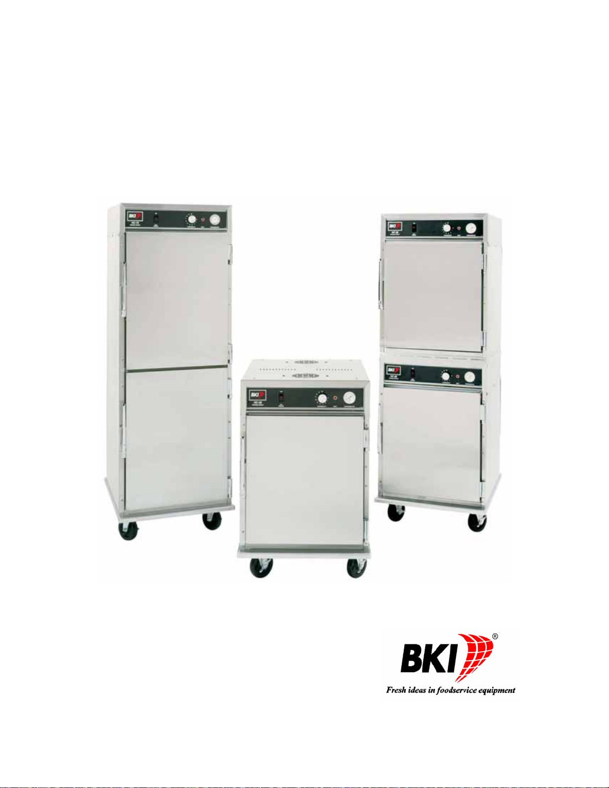
Heated/Humidified Holding Cabinet
Models HC-36, HC-36/2, HC-72
Service Manual
Serial Numbers 122695 and Higher
Page 2

Warranty Information
LIMITED ONE YEAR WARRANTY
BKI (The "Company") warrants to the original purchaser that at time of shipment from the
Company factory, this equipment will be free from defect in materials and workmanship. Written
notice of a claim under this warranty must be received by the Company within ONE YEAR from
the date of installation, but no longer than ONE YEAR AND THREE MONTHS from date of
shipment from the factory. Defective conditions caused by abnormal use or misuse, lack of or
improper maintenance, damage by third parties, alterations by unauthorized personnel, acts of
God, failure to follow installation and/or operating instructions, or any other events beyond the
reasonable control of the Company will NOT be covered under this warranty. The obligation of
the Company under this warranty shall be limited to repairing or replacing (at the option of the
Company) any part, with the exception of lamps, fuses, and glass (which are not covered under
warranty), which is found defective in the reasonable opinion of the Company. Any part found
defective by the Company will be repaired or replaced without charge F.O.B. factory,
Simpsonville, South Carolina or F.O.B. authorized BKI Distributor. The Company and/or its
authorized representatives will assume the normal replacement labor expense for the defective
part for the period of the warranty as stated above, excluding travel and/or other expenses
incidental to the replacement of the defective part, where replacement work is performed during
standard business hours and not subject to overtime, holiday rates, and/or any additional fees. IN
NO EVENT SHALL THE COMPANY BE LIABLE FOR LOSS OF USE, LOSS OF REVENUE OR
LOSS OF PRODUCT OR PROFIT OR FOR INDIRECT OR CONSEQUENTIAL DAMAGES
INCLUDING BUT NOT LIMITED TO, FOOD SPOILAGE OR PRODUCT LOSS. WARRANTY
DOES NOT COVER GLASS BREAKAGE. THE ABOVE WARRANTY IS EXCLUSIVE AND ALL
OTHER WARRANTIES, EXPRESS OR IMPLIED, ARE EXCLUDED INCLUDING THE IMPLIED
WARRANTIES OF MERCHANTABILITY AND FITNESS FOR A PARTICULAR PURPOSE.
REPLACEMENT PARTS
Any appliance replacement part, with the exception of lamps, fuses, and glass, which proves to
be defective in material or workmanship within ninety (90) days of installation will be replaced
without charge F.O.B. Factory, Simpsonville, SC or F.O.B. authorized BKI Distributor. The user
shall have the responsibility and expense of removing and returning the defective part to the
Company as well as the cost of reinstalling the replacement or repaired part.
Page 3

Heated/Humidified Holding Cabinet Table of Contents
Table of Contents
Table of Contents .................................................................................................................................................... 1
Introduction.............................................................................................................................................................. 2
Safety Precautions................................................................................................................................................ 2
Safety Signs and Messages ............................................................................................................................. 2
Safe Work Practices ......................................................................................................................................... 3
Safety Labels .................................................................................................................................................... 5
Installation................................................................................................................................................................ 6
Instructions For Shipping Damage........................................................................................................................ 6
Location and Placement........................................................................................................................................ 6
Electrical Information............................................................................................................................................. 6
Replacement Parts .................................................................................................................................................. 7
Assemblies............................................................................................................................................................ 7
Accessories......................................................................................................................................................... 28
Wiring Diagrams.................................................................................................................................................... 29
Notes....................................................................................................................................................................... 33
1
Page 4
Heated/Humidified Holding Cabinet Introduction
Introduction
Congratulations! You have chosen a Heated/Humidified Holding Cabinet that will give you many years of fine
service from the original manufacturer, BKI.
The BKI name and trademark on this unit assures you of the finest in design and engineering — that it has been
built with care and dedication — using the best materials available. Attention to the operating instructions
regarding proper installation, operation, and maintenance will result in long lasting dependability to insure th e
highest profitable return on your investment.
PLEASE READ THIS ENTIRE MANUAL BEFORE OPERATING THE UNIT. If you have
any questions, please contact your BKI Distributor. If they are unable to answer your
questions, contact the BKI Technical Service Department, toll free: 1-800-927-6887.
Outside the U.S., call 1-864-963-3471.
Safety Precautions
Always follow recommended safety precautions listed in this manual. Below is the safety alert symbol. When you
see this symbol on your equipment, be alert to the potential for personal injury or property damage.
Safety Signs and Messages
The following Safety signs and messages are placed in this manual to provide instructions and identify specific
areas where potential hazards exist and special precautions should be taken. Know and un derstand the meaning
of these instructions, signs, and messages. Damage to the equipment, death or serious injury to you or other
persons may result if these messages are not followed.
This message indicates an imminently hazardous situation that, if not avoided, will result
in death or serious injury.
This message indicates a potentially hazardous situation, which, if not avoided, could
result in death or serious injury.
This message indicates a potentially hazardous situation, which, if not avoided, may
result in minor or moderate injury. It may also be used to alert against unsafe practices.
This message is used when special information, instructions or identification are required
relating to procedures, equipment, tools, capacities and other special data.
2
Page 5
Heated/Humidified Holding Cabinet Introduction
Safe Work Practices
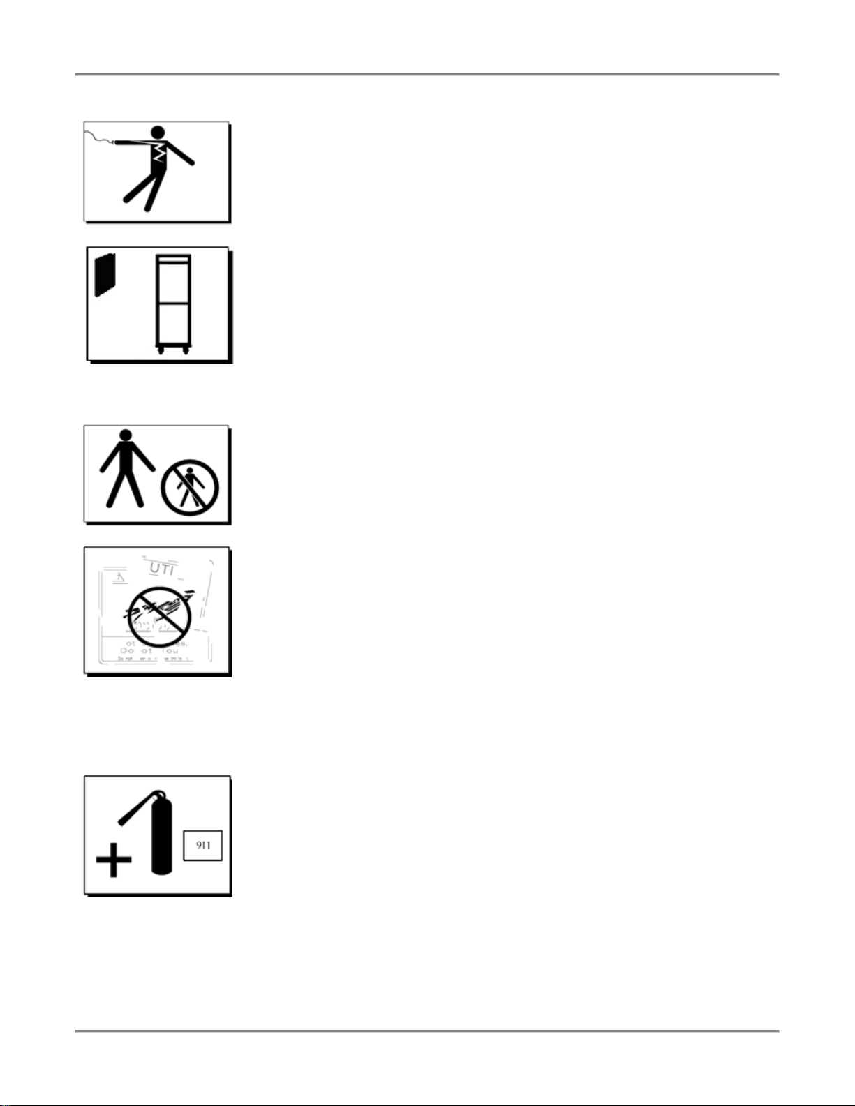
Beware of High Voltage
This equipment uses high voltage. Serious injury can occur if you or any untrained
or unauthorized person installs, services, or repairs this equipment. Always Use an
Authorized Service agent to Service Your Equipment.
Keep this manual with the Equipment
This manual is an important part of your equipment. Always keep it near for easy
access. If you need to replace this manual, contact:
BKI
Technical Services Department
P.O. Box 80400
Simpsonville, S.C. 29680-0400
Or call toll free: 1-800-927-6887
Outside the U.S., call 864-963-3471
Protect Children
Keep children away from this equipment. Children may not understand that this
equipment is dangerous for them and others.
NEVER allow children to play near or operate your equipment.
Keep Safety Labels Clean and in Good Condition
Do not remove or cover any safety labels on your equipment. Keep all safety labels
clean and in good condition. Replace any damaged or missing safety labels. Refer
to the Safety Labels section for illustration and location of safety labels on this unit.
If you need a new safety label, obtain the number of the specific label illustrated on
page 5, then contact:
BKI
Technical Services Department
P.O. Box 80400
Simpsonville, S.C. 29680-0400
Or call toll free: 1-800-927-6887
Outside the U.S., call 864-963-3471
Be Prepared for Emergencies
Be prepared for fires, injuries, or other emergencies.
Keep a first aid kit and a fire extinguisher near the equipment. You must use a 40-
pound Type BC fire extinguisher and keep it within 25 feet of your equipment.
Keep emergency numbers for doctors, ambulance services, hospitals, and the fire
department near your telephone.
3
Page 6

Heated/Humidified Holding Cabinet Introduction
Know your responsibilities as an Employer
• Make certain your employees know how to operate the equipment.
• Make certain your employees are aware of the safety precautions on the
equipment and in this manual.
• Make certain that you have thoroughly trained your employees about operating
the equipment safely.
• Make certain the equipment is in proper working condition. If you make
unauthorized modifications to the equipment, you will reduce the function and
safety of the equipment.
4
Page 7
Heated/Humidified Holding Cabinet Introduction
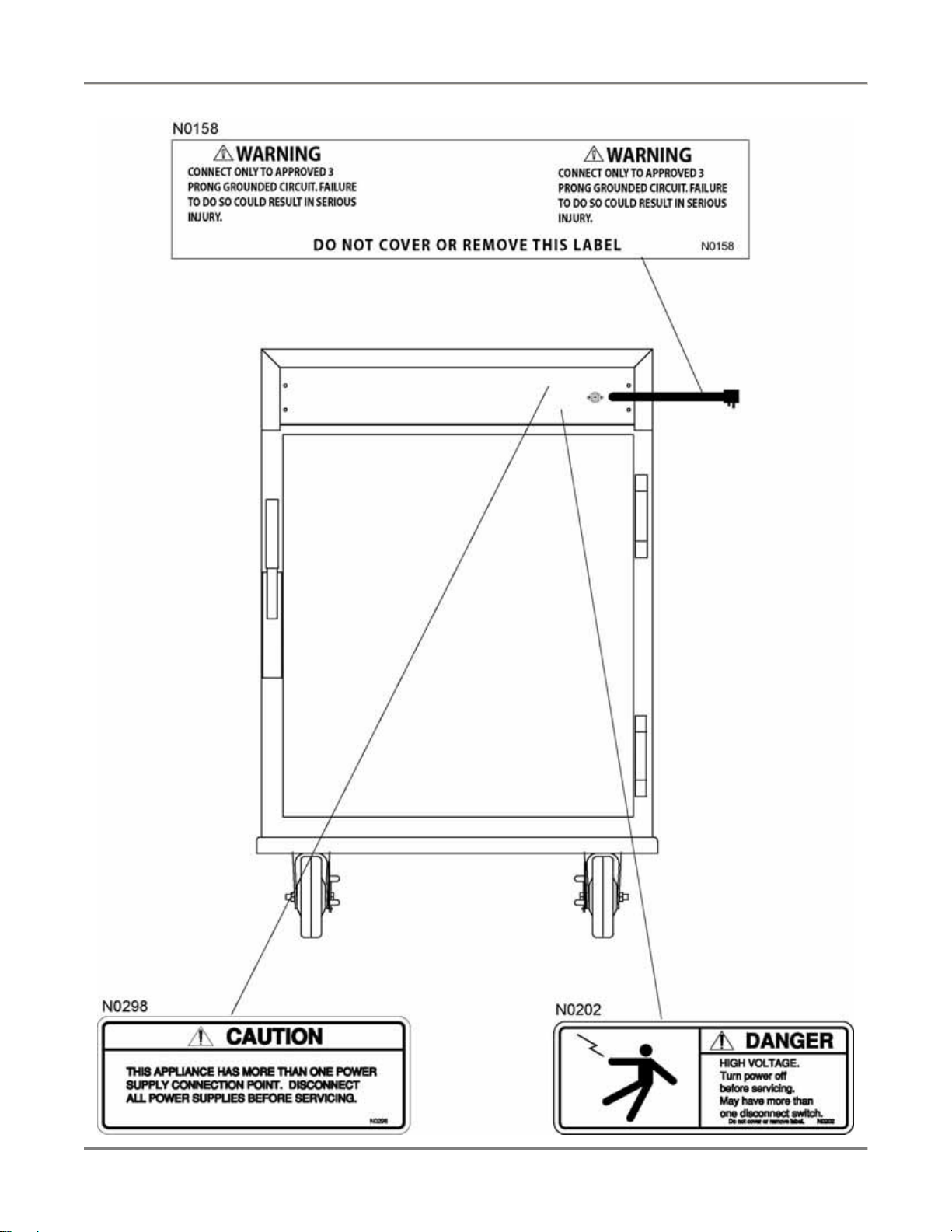
Safety Labels
5
Page 8

Heated/Humidified Holding Cabinet Installation
Installation
Serious injury, equipment damage or death could result if attempting to install this unit
yourself. Ensure that an authorized BKI service agent installs the unit.
Instructions For Shipping Damage
You are responsible for filing all freight claims with the delivering truck line. Inspect all cartons and crates for
damage when they arrive. If there is damage noted to shipping crates or cartons, or, if a shortage is found, note
this on the bill of lading (all copies) before signing.
If damage is detected when the equipment is uncrated, immediately call the delivering truck line and follow up the
call with a written report indicating concealed damage to your equipment. Ask for an immediate inspection of your
concealed damage item. Crating material MUST be retained to show the inspector from the truck line.
Location and Placement
Move the unit to a permanent location and lock the swivel casters before using.
Electrical Information
Electrocution, equipment failure or property damage could result if an unlicensed
electrician performs the electrical installation. Ensure that a licensed electrician perform
the electrical installation in accordance with local codes, or in the absence of local codes,
with the National Electrical Code, ANSI NFPA 70-20XX.
This unit, when installed by an authorized BKI service agent, must be wired for use in accordance with all
applicable local, state, and federal codes. For specific electrical requirements and connection s refer to the wiring
diagram attached to the unit or provided in the Service Manual.
6
Page 9
Heated/Humidified Holding Cabinet Replacement Parts
Replacement Parts
Use the information in this section to identify replacement parts. To order replacement parts, call your local BKI
sales and service representative. Before calling, please note the serial number on the rating tag affixed to the unit.
Assemblies
Description Assembly # Figure # Table #
BASE (HC72, HC36) AB57028800
AB57008000
DOOR HARDWARE (HC36 LEFT HINGE) AN57020800 Figure 2 Table 2
DOOR/HARDWARE (HC36 RIGHT HINGE) AB57017100 Figure 4 Table 4
DOOR/HARDWARE (HC72 LEFT HINGE) AB57018300 Figure 5 Table 5
DOOR/HARDWARE (HC72 RIGHT HINGE) AB57015700 Figure 7 Table 7
HEAT MODULE (120V HC36 VENTED)
HEAT MODULE (120V HC36)
HEAT MODULE (120V HC72)
HEAT MODULE (240V HC72 VENTED)
HEAT MODULE (HC36 ENGLAND)
HEAT MODULE (HC72 ENGLAND)
TRAY RACK (HC36) AB57017000 Figure 14 LOWER TRAY RACK (HC72) AB57008200 Figure 15 UPPER TRAY RACK (HC72) AB57008300 Figure 16 -
AN57028300
AN57022600
AN57023700
AN57028000
AN57022700
AN57023800
Figure 1 Table 1
Figure 8 Table 8
7
Page 10
Heated/Humidified Holding Cabinet Replacement Parts
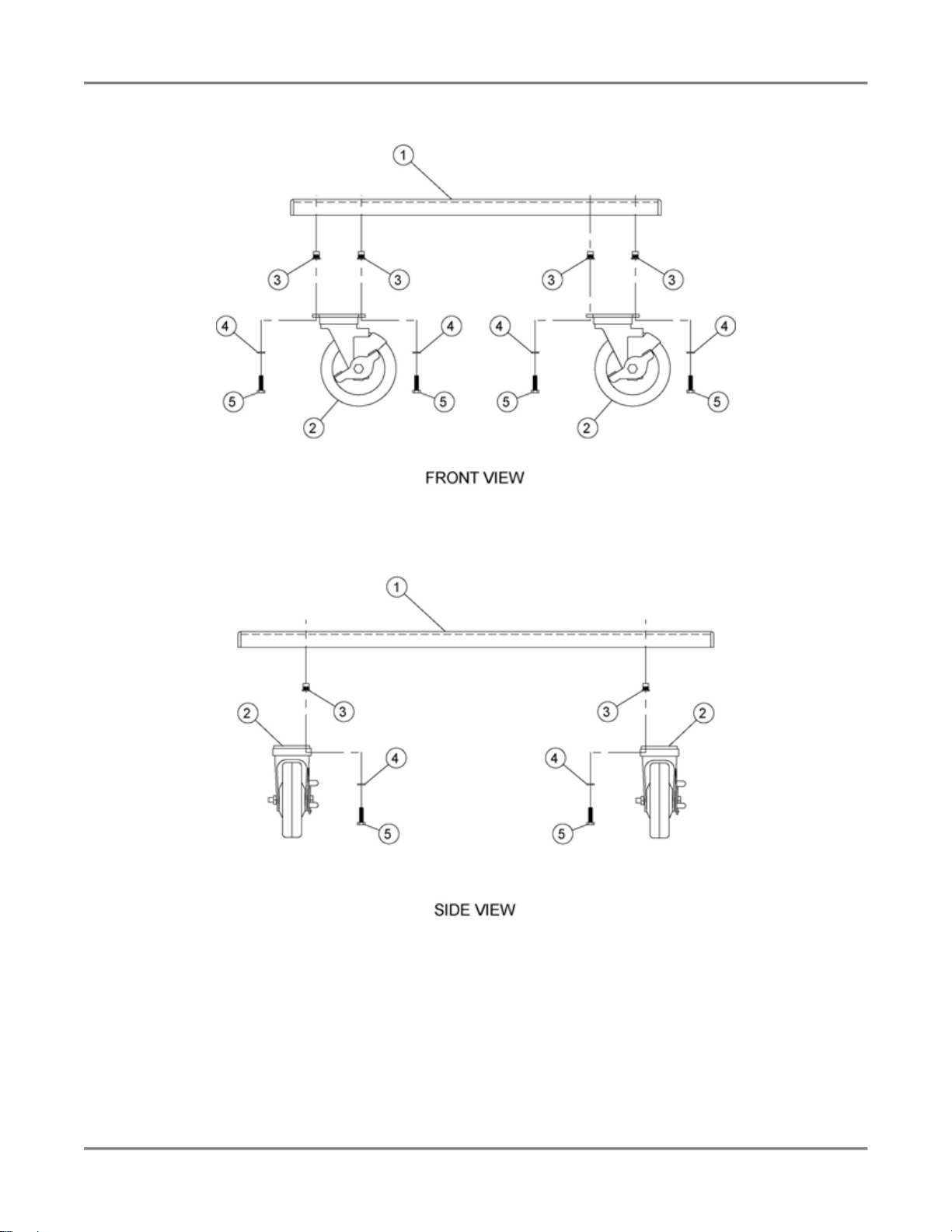
Figure 1. Base (HC72, HC36)
AB57028800
8
Page 11
Heated/Humidified Holding Cabinet Replacement Parts
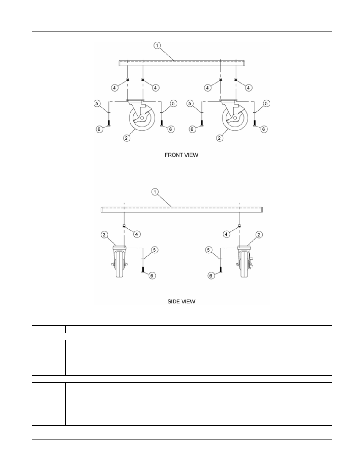
AB57008000
Table 1. Base (HC72, HC36) Parts
ITEM # PART # QTY DESCRIPTION
AB57028800
1 WB57013600 1 BASE WELDMENT HC'S FB57013610
2 C0415 4 CASTER, 3"SWIVEL W/BREAK
3 F0082 12 THREAD INSERT 1/4-20 STEEL
4 WSH102 12 WASHER, 1/4 INT LOCK
5 SCR060 12 SCREW, 1/4-20 X 1 HEX CAP
AB57008000
1 WB57013600 1 BASE WELDMENT HC'S
2 C0411 2 CASTER, W/BRAKE HC-36, 72
3 C0412 2 CASTER, W/O BRAKE
4 F0082 16 THREAD INSERT 1/4-20 STEEL
5 WSH102 16 WASHER, 1/4 INT LOCK
6 SCR060 16 SCREW, 1/4-20 X 1 HEX CAP
9
Page 12

Heated/Humidified Holding Cabinet Replacement Parts
Figure 2. Door Hardware (HC36 Left Hinge)
Table 2. Door Hardware (HC36 Left Hinge) Parts
ITEM # PART # QTY DESCRIPTION
1 AC57009200 (see Figure 3) 1 DOOR ASSY HC36
2 H0008 2 HINGE, FOR HC-36, 72
3 L0100 1 LATCH, MAGNETIC HC-36, 72
4 SCR197 8 SCREW, 10-24 X 1 1/2 PHIL FL
10
Page 13

Heated/Humidified Holding Cabinet Replacement Parts
Figure 3. Door Assembly HC36
Table 3. Door Assembly HC36 Parts
ITEM # PART # QTY DESCRIPTION
1 WB57004200 1 DOOR, CORNERS WELDED
2 FB57004102 1 INSIDE DOOR, HC-36
3 MB57011210 1 MOUNTING PLATE, HINGE HC-36
4 MB57005410 1 MOUNTING PLATE, LATCH HC
5 SCR383 4 SCREW, 10-24 X 1/2" PHIL TRUSS HD
6 I0010 3.5 SF INSULATION, RANGE 1" FIBERGLASS
7 RIV180 16 RIVET,1/8 SS (.063-.125)
11
Page 14

Heated/Humidified Holding Cabinet Replacement Parts
Figure 4. Door/Hardware (HC36 Right Hinge)
Table 4. Door/Hardware (HC36 Right Hinge) Parts
ITEM # PART # QTY DESCRIPTION
1 AC57009200 (see Figure 3) 1 DOOR ASSY HC36
2 H0008 2 HINGE, FOR HC-36, 72
3 L0100 1 LATCH, MAGNETIC HC-36, 72
4 SCR197 8 SCREW, 10-24 X 1 1/2 PHIL FL
12
Page 15

Heated/Humidified Holding Cabinet Replacement Parts
Figure 5. Door/Hardware (HC72 Left Hinge)
Table 5. Door/Hardware (HC72 Left Hinge) Parts
ITEM # PART # QTY DESCRIPTION
1 AC57007900 (see Figure 6) 1 DOOR ASSY HC72
2 H0008 2 HINGE, FOR HC-36, 72
3 L0100 1 LATCH, MAGNETIC HC-36, 72
4 SCR197 8 SCREW, 10-24 X 1 1/2 PHIL FL
13
Page 16

Heated/Humidified Holding Cabinet Replacement Parts
Figure 6. Door Assembly HC72
Table 6. Door Assembly HC72 Parts
ITEM # PART # QTY DESCRIPTION
1 WB57000300 1 DOOR, CORNERS WELDED HC72
2 FB57024902 1 INSIDE DOOR HC72
3 MB57005410 1 MOUNTING PLATE, LATCH HC
4 MB57005100 1 MTG PLATE, HINGE HC72
5 SCR383 4 SCREW, 10-24 X 1/2" PHIL TRUSS HD
6 I0010 4 INSULATION, RANGE 1" FIBERGLASS
7 RIV180 16 RIVET,1/8 SS (.063-.125)
14
Page 17

Heated/Humidified Holding Cabinet Replacement Parts
Figure 7. Door/Hardware (HC72 Right Hinge)
Table 7. Door/Hardware (HC72 Right Hinge) Parts
ITEM # PART # QTY DESCRIPTION
1 AC57007900 (see Figure 6) 1 DOOR ASSY HC72
2 H0008 2 HINGE, FOR HC-36, 72
3 L0100 1 LATCH, MAGNETIC HC-36, 72
4 SCR197 8 SCREW, 10-24 X 1 1/2 PHIL FL
15
Page 18

Heated/Humidified Holding Cabinet Replacement Parts
Y
Figure 8. Heat Module
CONTROL PANEL HEAT BOX
RELA
POWER PANEL
BLOWER ASSEMBLY
16
Page 19

Heated/Humidified Holding Cabinet Replacement Parts
Table 8. Heat Module Parts
PART QTY DESCRIPTION FIGURE # TABLE #
R0002
or
R0004
1 RELAY, 2 POLE 110/120V
or
RELAY, 2 POLE 208/240V
Figure 8 -
AB57022500 2 BLOWER (HC 36/72, 230V) Figure 9 Table 9
AB57022400 2 BLOWER (HC36/72, 120V) Figure 10 Table 10
AN57022800
AN57023000
AN57027200
AN57023600
AN57024000
AN57028400
AC57022200
AN57023500
AN57024100
AN57023900
AN57028700
AN57027300
AN57022900
AN57023100
1
CONTROL PANEL HC36 120V
1
CONTROL PANEL HC36 240V ENGLAND
1
CONTROL PANEL HC36 VENTED
1
CONTROL PANEL HC72 120V
1
CONTROL PANEL HC72 240V ENGLAND
1
CONTROL PANEL HC72 VENTED
1
HEAT BOX HC36 120V
1
HEAT BOX HC72 120V
1
HEAT BOX HC36 230V ENGLAND
1
HEAT BOX HC72 240V ENGLND
1
POWER SUPPLY PANEL 120V HC36/72 VENTED
1
POWER SUPPLY PANEL 240V HC36/72 VENTED
1
POWER SUPPLY PANEL HC72 120V
1
POWER SUPPLY PANEL HC72 240V
Figure 11 Table 11
Figure 12 Table 12
Figure 13 Table 13
17
Page 20

Heated/Humidified Holding Cabinet Replacement Parts
Figure 9. Blower (HC 36/72, 230V)
Table 9. Blower (HC 36/72, 230V) Parts
ITEM # PART # QTY DESCRIPTION
1 M0068 1 MOTOR, 208/240V 60 HZ
2 FN0008 1 FAN BLADE
3 FN0009 1 BLOWER HOUSING
4 FN0010 1 INLET RING
5 FN0011 1 BLOWER WHEEL, 3" DIA 1 1/2" W
6 G0085 1 GASKET, SILICONE RUBBER HC
7 FB57021410 1 INTAKE COVER, HC36 AIR DIS BOX
8 FB57002902 1 BLOWER MTG PLATE
9 SCR323 2 SCREW, 6-32 X 1/2 PHIL RD
10 SCR117 2 SCREW, 6-32 X 3/8 PHIL RD
11 FB57021510 1 INTAKE BODY AIR DIST BOX HC36
12 SCR354 6 SCREW, 8 X 1/2 PHIL PAN
13 TP0021 0.63 FT TAPE, ARMAFLEX 1/8 X 3/4 X 50'
14 RIV171 6 RIVET, 1/8 ALUM (.187-.250)
18
Page 21

Heated/Humidified Holding Cabinet Replacement Parts
Figure 10. Blower (HC 36/72, 120V)
Table 10. Blower (HC 36/72, 120V) Parts
ITEM # PART # QTY DESCRIPTION
1 M0063 1 MOTOR, 120V SHADED POLE
2 FN0008 1 FAN BLADE
3 FN0009 1 BLOWER HOUSING
4 FN0010 1 INLET RING
5 FN0011 1 BLOWER WHEEL, 3" DIA 1 1/2" W
6 G0085 1 GASKET, SILICONE RUBBER HC
7 FB57021410 1 INTAKE COVER, HC36 AIR DIS BOX
8 FB57002902 1 BLOWER MTG PLATE
9 FSA113 1 FAN SUPPORT
10 SCR118 2 SCREW, 6-32 X 5/8 SLTD RD
11 FB57021510 1 INTAKE BODY AIR DIST BOX HC36
12 SCR354 6 SCREW,8 X 1/2 PHIL PAN
13 TP0021 0.63 FT TAPE, ARMAFLEX 1/8 X 3/4 X 50'
14 RIV171 6 RIVET, 1/8 ALUM (.187-.250)
19
Page 22

Heated/Humidified Holding Cabinet Replacement Parts
Figure 11. Control Panel
20
Page 23

Heated/Humidified Holding Cabinet Replacement Parts
Table 11. Control Panel Parts
ITEM # PART # QTY DESCRIPTION
1 N0431
or
N0432
2 N0447
or
N0448
1
DECAL, CONTROL PANEL HC36
or
DECAL, CONTROL PANEL HC72
DECAL, HC36 VENTED CONTROL PNL
or
DECAL, HC72 VENTED CONTROL PNL
3 K0041 1 KNOB, BLACK W/BUSHING
4 K0045 1 KNOB, BLK
5 PL0004 1 PILOT LIGHT, ROUND 250V
6 S0102
or
S0107
7 TG0024
or
TG0001
1
1
SWITCH, RCKR SPST W/LITE 250V
or
SWITCH, RKR SPST 15A 125V LAMP
THERMOMETER 100-220 F/C 36" CAP.
or
THERMOMETER 30-300 F/C 72" CAP.
8 T0071 1 THERMOSTAT
21
Page 24

Heated/Humidified Holding Cabinet Replacement Parts
Figure 12. Heat Box
22
Page 25

Heated/Humidified Holding Cabinet Replacement Parts
Table 12. Heat Box Parts
ITEM # PART # QTY DESCRIPTION
1 FB57001610 2 AIR DEFLECTOR
2 FB57001502 2 AIR BAFFLE
3 G0084 2 GASKET, CLOSED CELL NEOPRENE
4 FB57021310 1 HEAT MODULE DIST BOX HC36
5 FB57021609 2 BRACE, TOP HC36
6 C0287B
or
C0288B
or
C0303B
or
C0304B
2
CALROD, 120V 1000W W/BRACKET
or
CALROD, 120V 750W W/BRACKET
or
CALROD, 240V 1000W W/BRACKET
or
CALROD, 240V 750W W/BRACKET
7 T0074 2 TEMP SENSOR
8 F0155 * 2 BUSHING, BLK 7/8 HEYCO SNAP
9 SCR354 26 SCREW, 8 X 1/2 PHIL PAN
10 FB57022310 2 GASKET RETAINING FRAME, HC36
* - Not shown on drawing.
23
Page 26

Heated/Humidified Holding Cabinet Replacement Parts
Figure 13. Power Supply Panel
Table 13. Power Supply Panel Parts
ITEM # PART # QTY DESCRIPTION
1 CS0024 1 CORD SET, 12/3 SJTO 8' 30"LEAD
2 FH0001 1 FUSE HOLDER, 15A 300V
3 F0123
or
F0124
1
FUSE, 2A SC2 BUSSMAN
or
FUSE, 4A SC4 BUSSMAN
4 LZ0024 1 POWER SUPPLY PANEL LASER CUT HC
5 FB57021903 1 POWER SUPPLY PANEL, HC36
24
Page 27

Heated/Humidified Holding Cabinet Replacement Parts
Figure 14. Tray Rack (HC36)
25
Page 28

Heated/Humidified Holding Cabinet Replacement Parts
Figure 15. Lower Tray Rack (HC72)
26
Page 29

Heated/Humidified Holding Cabinet Replacement Parts
Figure 16. Upper Tray Rack (HC72)
27
Page 30

Heated/Humidified Holding Cabinet Replacement Parts
Accessories
PART # DESCRIPTION PICTURE
G0052 Insulated Mitt, 13”
P0057 Pan, Bun Sheet
R0075 Rack
28
Page 31

Heated/Humidified Holding Cabinet Wiring Diagrams
Wiring Diagrams
Refer to the table below to find the wiring diagram associated with your unit.
Wiring Diagram Part # Figure #
HC36/72 120V/1 Phase SA57021200 Figure 17
HC36/72 220V/1 Phase SA57090000 Figure 19
HC36/72 240V/1 Phase (ENGLAND) SA57023200 Figure 18
29
Page 32

Heated/Humidified Holding Cabinet Wiring Diagrams
Figure 17. HC36/72 120V/1 Phase
30
Page 33

Heated/Humidified Holding Cabinet Wiring Diagrams
Figure 18. HC36/72 220V/1 Phase
31
Page 34

Heated/Humidified Holding Cabinet Wiring Diagrams
Figure 19. HC36/72 240V/1 Phase (ENGLAND)
32
Page 35

Heated/Humidified Holding Cabinet Notes
Notes
33
Page 36

P.O. Box 80400, Simpsonville, S.C. 29680-0400, USA
http://www.bkideas.com
Made and printed in the U.S.A
LI0258/0407
 Loading...