

Page 1
Fry Warmer
MODELS FW-12, FW-15, FW-12T, FW-15T, FW-15DTO
Service Manual
Serial Numbers 120182 and Higher
CS-TM-025.01 Revised 3/26/13
Page 2

(864) 963-3471 • Toll Free: (800) 927-6887 • Fax: (864) 963-5316
WHAT IS
WHO IS
COVERAGE PERIOD
WARRANTY COVERAGE
EXCEPTIONS
EXCLUSIONS
INSTALLATION
REPLACEMENT PARTS
COVERED
COVERED
BKI LIMITED W ARRANTY
2812 Grandview Dr. • Simpsonville, SC 29680 • USA
This warranty covers defects in material and workmanship under normal use, and applies
only to the original purchaser providing that:
The equipment has not been accidentally or intentionally damaged, altered or misused;
The equipment is properly installed, adjusted, operated and maintained in accordance
national and local codes, and in accordance with the installation and operating
with
instructions provided with this product.
The serial number rating plate affixed to the equipment has not been defaced or
removed.
This
equipment purchased
Warranty claims must be received in writing by BKI within one (1) year from
date of installation or within one (1) year and three (3) months from data of
shipment from the factory, whichever comes first.
COB Models: One (1) Year limited parts and labor.
COM Models: Two (2) Year limited parts and labor. COM convection ovens also have
a two (2) year door warranty.
CO1 Models: Two (2) Year limited parts and labor. Five (5) Year limited door
warranty.
BevLes Products: Two (2) Year limited parts and labor.
Warranty period begins the date of dealer invoice to customer or ninety (90) days
after shipment date from BKI, whichever comes first.
This
warranty
xpenses
e
hours
travel time and
extended door warranty on convection ovens years 3 through 5 is a parts only warranty and
does not include labor, travel, mileage or any other charges.
Thermostat calibrations
Air and gas
Light
Glass doors and
Fuses,
Adjustments
Tightening
Failures
Unauthorized
Damage
Alteration,
Thermostats
Freight –
Ordinary
Failure to follow
Events
appropriate installation
per
installer, not the
BKI genuine
date of
warranty
covers on-site labor, parts and
of the
Any exceptions must be pre-approved in advance and in writing by BKI. The
Negligence
adjustments,
bulbs,
of screws or
caused
in
shipment,
misuse or
and safety valves with
other than normal UPS charges,
wear and
beyond control
Leveling, as well as
manufacturer.
Factory OEM parts receive a (90) day
installation
is
extended
for use in the U.S.A.
authorized
door adjustments,
to
burner
by erratic
repair by
installation and/or operating instructions,
by a BKI F
service
performed during regular, weekday business hours.
or acts of
after (30) days
flames and
fasteners,
voltages
anyone other than
improper installation,
tear,
of the
company.
proper installation
and use materials – is the responsibility of the
actory Authorized
to the original
representative
God,
from equipment installation date,
cleaning of
or gas
broken
purchaser
reasonable
suppliers,
a BKI F
capillary tubes,
and check out of all
Service
travel
up to (100) miles
pilot
burners,
actory Authorized
materials warranty
Center.
and applies only to
time
and travel
round
trip and (2)
Service Center,
new equipment -
dealer
effective from the
or
CS-TM-025.01 Revised 3/26/13
Page 3

Fry Warmer Table of Contents
Table of Contents
Table of Contents..................................................................................................................................................... 1
Introduction .............................................................................................................................................................. 2
Safety Precautions................................................................................................................................................. 2
Safety Signs and Messages.............................................................................................................................. 2
Safe Work Practices .......................................................................................................................................... 2
Safety Labels ......................................................................................................................................................... 4
Installation ................................................................................................................................................................ 5
Instructions For Shipping Damage ........................................................................................................................ 5
Electrical Information And Grounding.................................................................................................................... 5
Installation Instructions .......................................................................................................................................... 5
FW-12 & FW-12T (Side Breather)..................................................................................................................... 5
FW-15 (Side Breather) ...................................................................................................................................... 6
FW-15 (Bottom Breather) .................................................................................................................................. 7
FW-15T/FW-15DTO (Bottom Breather) ............................................................................................................ 9
Maintenance ........................................................................................................................................................... 10
Scheduled Maintenance ...................................................................................................................................... 10
Cleaning .......................................................................................................................................................... 10
Troubleshooting ................................................................................................................................................... 11
Repair .................................................................................................................................................................. 11
Lamp Replacement .........................................................................................................................................11
Replacement Parts................................................................................................................................................. 12
Components ........................................................................................................................................................ 12
FW-12/FW-15 CUF (Side Breather)................................................................................................................ 12
FW-12/FW-15 PASS THRU (Side Breather)................................................................................................... 14
FW-15 CUF (Bottom Breather) ....................................................................................................................... 16
FW-15 PASS THRU (Bottom Breather) .......................................................................................................... 18
FW-12T (Side Breather) .................................................................................................................................. 20
FW-15T (Bottom Breather) .............................................................................................................................. 21
FW-15DTO (Bottom Breather) ........................................................................................................................ 22
Accessories ......................................................................................................................................................... 24
Wiring Diagrams..................................................................................................................................................... 25
FW-12/FW-15 (Side Breather)............................................................................................................................. 25
FW-12/FW-15 (Bottom Breather) ........................................................................................................................ 26
FW-15 (220V England) ........................................................................................................................................ 27
FW-12T/FW-15T .................................................................................................................................................. 28
FW-15DTO (Bottom Breather)............................................................................................................................. 30
Notes ....................................................................................................................................................................... 32
1
Page 4

Fry Warmer Introduction
Introduction
Congratulations! You have chosen a Fry Warmer that will give you many years of fine service from the original
manufacturer, BKI.
The BKI name and trademark on this unit assures you of the finest in design and engineering — that it has been
built with care and dedication — using the best materials available. Attention to the operating instructions
regarding proper installation, operation, and maintenance will result in long lasting dependability to insure the
highest profitable return on your investment.
PLEASE READ THIS ENTIRE MANUAL BEFORE OPERATING THE UNIT. If you have
any questions, please contact your BKI Distributor. If they are unable to answer your
questions, contact the BKI Technical Service Department, toll free: 1-800-927-6887.
Outside the U.S., call 1-864-963-3471.
This unit must be sealed to the counter after it is installed to conform to NSF Standard 4,
Item 4.28. (Dow Corning RTV #732 Multi purpose Sealant.)
Safety Precautions
Always follow recommended safety precautions listed in this manual. Below is the safety alert symbol. When you
see this symbol on your equipment, be alert to the potential for personal injury or property damage.
Safety Signs and Messages
The following Safety signs and messages are placed in this manual to provide instructions and identify specific
areas where potential hazards exist and special precautions should be taken. Know and understand the meaning
of these instructions, signs, and messages. Damage to the equipment, death or serious injury to you or other
persons may result if these messages are not followed.
This message indicates an imminently hazardous situation that, if not avoided, will result
in death or serious injury.
This message indicates a potentially hazardous situation, which, if not avoided, could
result in death or serious injury.
This message indicates a potentially hazardous situation, which, if not avoided, may
result in minor or moderate injury. It may also be used to alert against unsafe practices.
This message is used when special information, instructions or identification are required
relating to procedures, equipment, tools, capacities and other special data.
Safe Work Practices
Beware of High Voltage
This equipment uses high voltage. Serious injury can occur if you or any untrained
or unauthorized person installs, services, or repairs this equipment. Always Use an
Authorized Service agent to Service Your Equipment.
2
Page 5
Fry Warmer Introduction
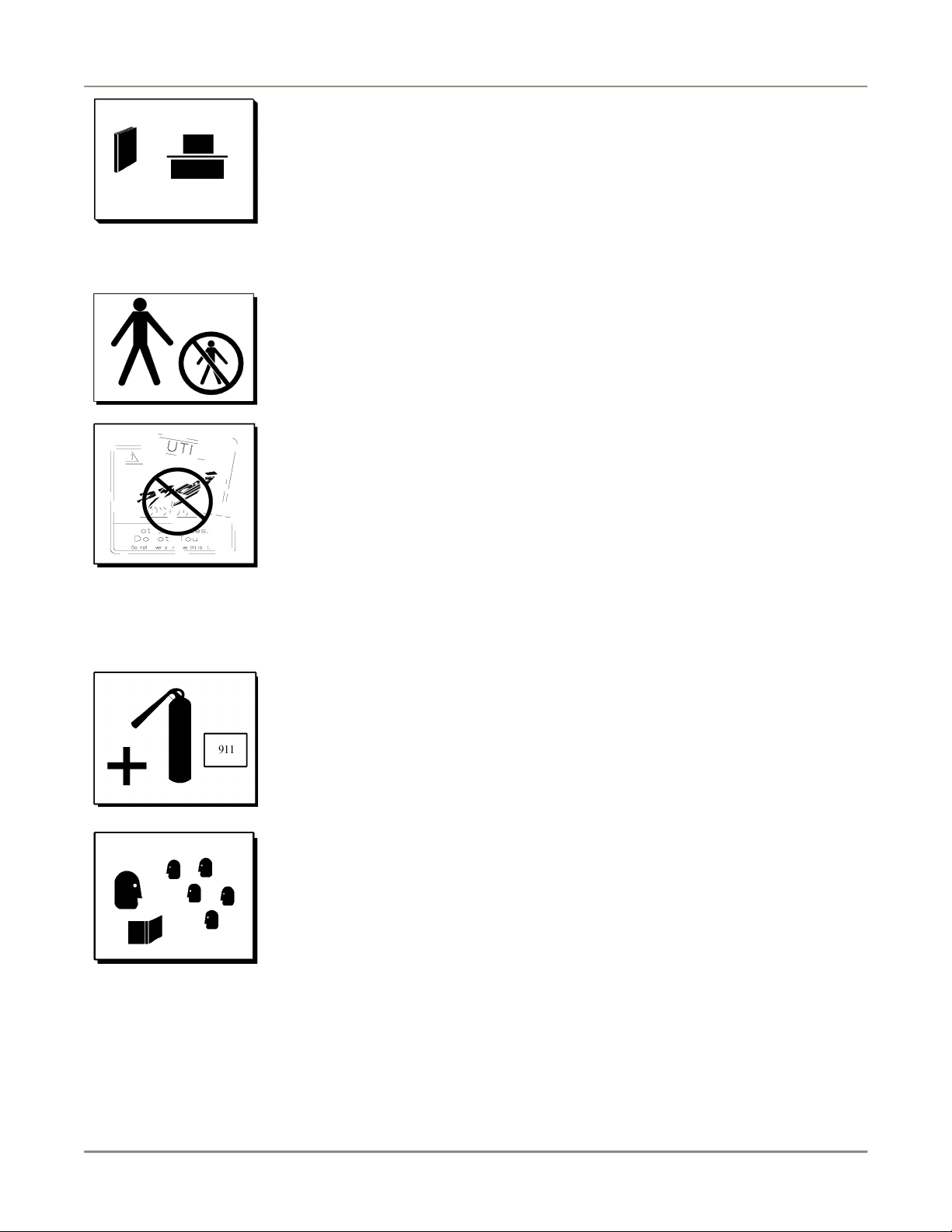
Keep this manual with the Equipment
This manual is an important part of your equipment. Always keep it near for easy
access. If you need to replace this manual, contact:
BKI
Technical Services Department
2812 Grandview Drive
Simpsonville, S.C. 29680
Or call toll free: 1-800-927-6887
Outside the U.S., call 864-963-3471
Protect Children
Keep children away from this equipment. Children may not understand that this
equipment is dangerous for them and others.
NEVER allow children to play near or operate your equipment.
Keep Safety Labels Clean and in Good Condition
Do not remove or cover any safety labels on your equipment. Keep all safety labels
clean and in good condition. Replace any damaged or missing safety labels. Refer
to the Safety Labels section for illustration and location of safety labels on this unit.
If you need a new safety label, obtain the number of the specific label illustrated on
page 4, then contact:
BKI
Technical Services Department
2812 Grandview Drive
Simpsonville, S.C. 29680
Or call toll free: 1-800-927-6887
Outside the U.S., call 864-963-3471
Be Prepared for Emergencies
Be prepared for fires, injuries, or other emergencies.
Keep a first aid kit and a fire extinguisher near the equipment. You must use a 40pound Type BC fire extinguisher and keep it within 25 feet of your equipment.
Keep emergency numbers for doctors, ambulance services, hospitals, and the fire
department near your telephone.
Know your responsibilities as an Employer
• Make certain your employees know how to operate the equipment.
• Make certain your employees are aware of the safety precautions on the
equipment and in this manual.
• Make certain that you have thoroughly trained your employees about operating
the equipment safely.
• Make certain the equipment is in proper working condition. If you make
unauthorized modifications to the equipment, you will reduce the function and
safety of the equipment.
3
Page 6

Fry Warmer Introduction
Safety Labels
4
Page 7

Fry Warmer Installation
Installation
Serious injury, equipment damage or death could result if attempting to install this unit
yourself. Ensure that an authorized BKI service agent install the oven.
Instructions For Shipping Damage
You are responsible for filing all freight claims with the delivering truck line. Inspect all cartons and crates for
damage when they arrive. If there is damage noted to shipping crates or cartons, or, if a shortage is found, note
this on the bill of lading (all copies) before signing.
If damage is detected when the equipment is uncrated, immediately call the delivering truck line and follow up the
call with a written report indicating concealed damage to your equipment. Ask for an immediate inspection of your
concealed damage item. Crating material MUST be retained to show the inspector from the truck line.
Electrical Information And Grounding
Electrocution, equipment failure or property damage could result if an unlicensed
electrician performs the electrical installation. Ensure that a licensed electrician perform
the electrical installation in accordance with local codes, or in the absence of local codes,
with the National Electrical Code, ANSI NFPA 70-20XX.
The FW-15DTO has 2 power supply cords. Ensure that each cord is connected to a
separate power supply circuit. Always unplug both power cords before servicing, moving
or testing the unit.
BKI Fry Warmers are wired for use in accordance with all applicable local, state, and federal codes. For specific
electrical requirements and connections refer to the wiring diagram attached to the unit or provided in the Service
Manual.
Installation Instructions
If a side or back panel is removed on the chute, the other two sides must be sealed with
NSF approved silicone. Seal all inside seams greater than 1/32”.
FW-12 & FW-12T (Side Breather)
Countertop Adapter (FW-12 only)
1. Obtain a suitable countertop location for the unit that will provide a clearance of 4” from the side louvers.
2. Position the adapter (WN31206400) on the countertop.
3. Using a 1/8” drill bit, drill holes in the countertop used to secure the adapter to the countertop.
4. Using a 2” hole saw, drill a hole in the countertop (directly under the hole in the adapter) used for the
power cord to pass through.
5. Secure adapter to countertop with # 8 sheet metal screws.
6. Seal adapter to the countertop to conform to NSF Standard 4, Item 4.28. (Dow Corning RTV #732 Multi
purpose Sealant.)
7. Feed power cord (supplied), up through holes in countertop and adapter.
5
Page 8

Fry Warmer Installation
8. Connect wires of power cord to power entry terminal block according to the wiring diagram attached to
the unit or provided in the Service Manual.
9. Position main unit on the adapter and secure using #8 sheet metal screws.
10. Fit pan insert to main unit by lifting the open side of pan insert over the two tabs on main unit and lower
the pan insert into the opening in the adapter.
Countertop Cutout (FW-12 & FW-12T)
1. Obtain a suitable countertop location for the unit that will provide a clearance of 4” from the side louvers.
2. Cut a 12” x 20” hole in the countertop to fit the pan insert.
3. Using a 1/8” drill bit, drill holes in the countertop used to secure the main unit to the countertop.
4. Using a 2” hole saw, drill a hole in the countertop (under where the main unit will be secured) for the
power cord to pass through.
5. Feed power cord (supplied), up through hole in countertop.
6. Connect wires of power cord to power entry terminal block according to the wiring diagram attached to
the unit or provided in the Service Manual.
7. Position main unit on the countertop and secure using #8 sheet metal screws.
8. Seal main unit to the countertop after it is installed to conform to NSF Standard 4, Item 4.28. (Dow
Corning RTV #732 Multi purpose Sealant.)
9. Fit pan insert to main unit by lifting the open side of pan insert over the two tabs on main unit and lower
the pan insert into the opening in the countertop.
FW-15 (Side Breather)
Countertop Adapter (WN31206500)
1. Obtain a suitable countertop location for the unit that will provide a clearance of 4” from the side louvers.
2. Position the adapter (WN31206500) on the countertop.
3. Using a 1/8” drill bit, drill holes in the countertop used to secure the adapter to the countertop.
4. Using a 2” hole saw, drill a hole in the countertop (directly under the hole in the adapter) used for the
power cord to pass through.
5. Secure adapter to countertop with # 8 sheet metal screws.
6. Seal adapter to the countertop to conform to NSF Standard 4, Item 4.28. (Dow Corning RTV #732 Multi
purpose Sealant.)
7. Feed power cord (supplied), up through holes in countertop and adapter.
8. Connect wires of power cord to power entry terminal block according to the wiring diagram attached to
the unit or provided in the Service Manual.
9. Position main unit on the adapter and secure using #8 sheet metal screws.
10. Fit pan insert to main unit by lifting the open side of pan insert over the two tabs on main unit and lower
the pan insert into the opening in the adapter.
6
Page 9
Fry Warmer Installation
Countertop Cutout
1. Obtain a suitable countertop location for the unit that will provide a clearance of 4” from the side louvers.
2. Cut a 16” x 18” hole in the countertop to fit the pan insert.
3. Using a 1/8” drill bit, drill holes in the countertop used to secure the main unit to the countertop.
4. Using a 2” hole saw, drill a hole in the countertop (under where the main unit will be secured) for the
power cord to pass through.
5. Feed power cord (supplied), up through hole in countertop.
6. Connect wires of power cord to power entry terminal block according to the wiring diagram attached to
the unit or provided in the Service Manual.
7. Position main unit on the countertop and secure using #8 sheet metal screws.
8. Seal main unit to the countertop to conform to NSF Standard 4, Item 4.28. (Dow Corning RTV #732 Multi
purpose Sealant.)
9. Fit pan insert to main unit by lifting the open side of pan insert over the two tabs on main unit and lower
the pan insert into the opening in the countertop.
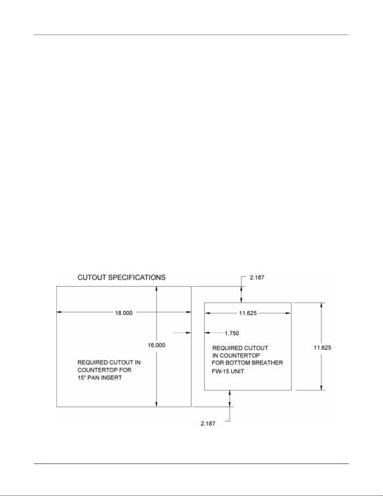
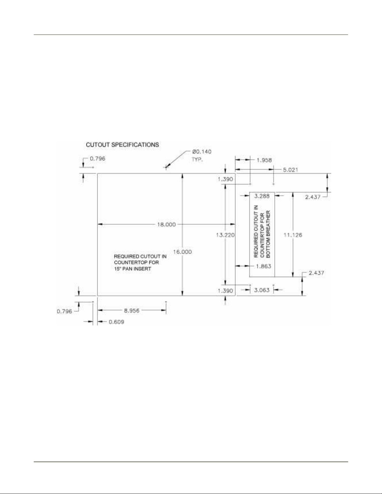
FW-15 (Bottom Breather)
Countertop Collar Weldment With Liner Pan (WB31216000)
1. Obtain a suitable countertop location for the unit.
2. Cut holes in the countertop for the countertop collar weldment with liner pan (WB31216000) according to
illustration below:
3. Using a 1/8” drill bit, drill holes in the countertop used to secure WB31216000 to the countertop.
7
Page 10
Fry Warmer Installation
4. Secure WB31216000 to countertop with # 8 sheet metal screws.
5. Seal WB31216000 to the countertop to conform to NSF Standard 4, Item 4.28. (Dow Corning RTV #732
Multi purpose Sealant.)
6. Feed power cord (supplied), up through holes in WB31216000.
7. Connect wires of power cord to power entry terminal block according to the wiring diagram attached to
the unit or provided in the Service Manual.
8. Position main unit on WB31216000.
9. Fit pan insert to main unit by lifting the open side of pan insert over the two tabs on main unit and lower
the pan insert into the opening in the WB31216000.
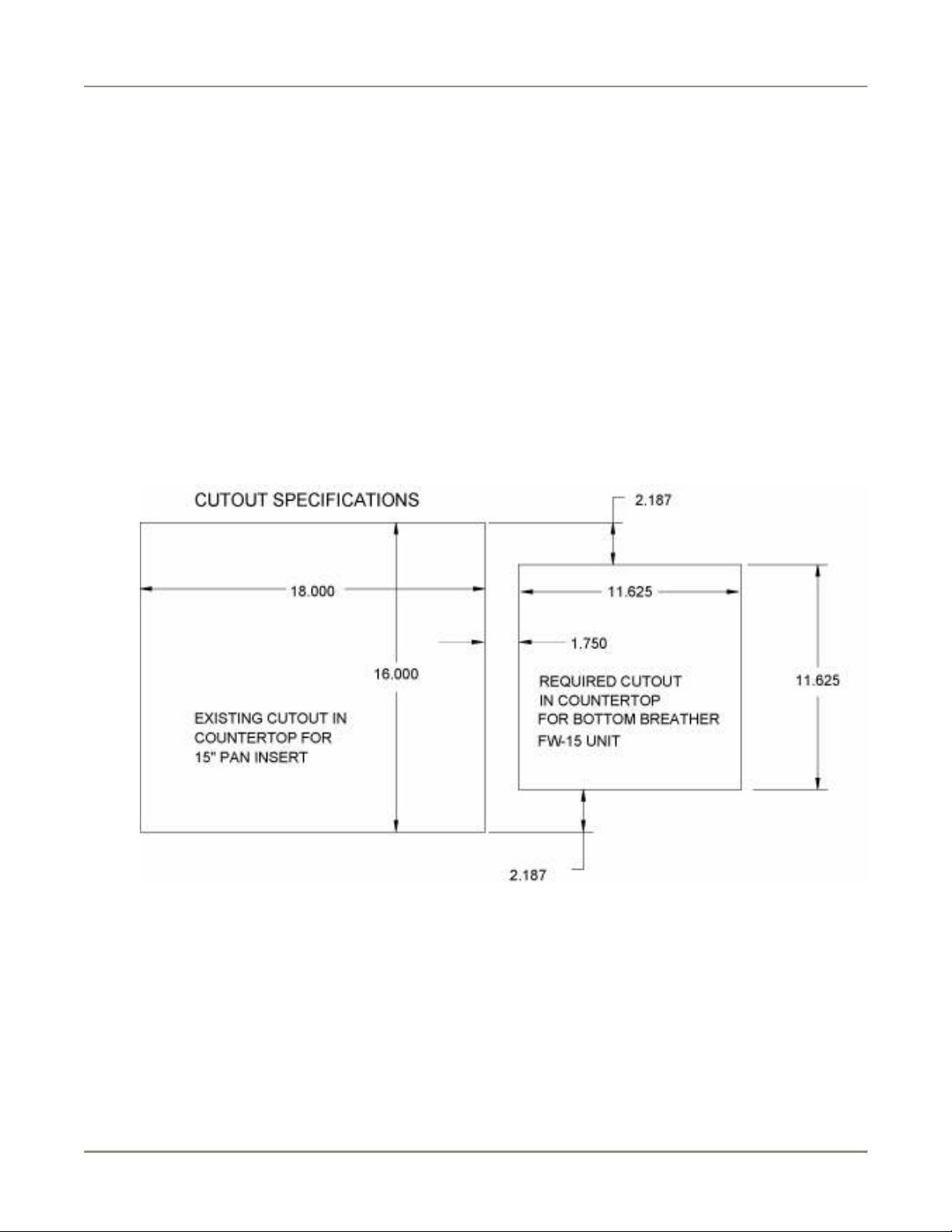
Countertop Collar Weldment Without Liner Pan (WB31211900)
1. Obtain a suitable countertop location for the unit.
2. Cut a hole in the countertop for the countertop collar weldment without liner pan (WB31211900)
according to illustration below:
3. Using a 1/8” drill bit, drill holes in the countertop used to secure WB31211900 to the countertop.
4. Secure WB31211900 to countertop with # 8 sheet metal screws.
5. Seal WB31211900 to the countertop to conform to NSF Standard 4, Item 4.28. (Dow Corning RTV #732
Multi purpose Sealant.)
6. Feed power cord (supplied), up through holes in WB31211900.
7. Connect wires of power cord to power entry terminal block according to the wiring diagram attached to
the unit or provided in the Service Manual.
8
Page 11
Fry Warmer Installation
8. Position main unit on WB31211900.
9. Fit pan insert to main unit by lifting the open side of pan insert over the two tabs on main unit and lower
the pan insert into the opening in the countertop.
FW-15T/FW-15DTO (Bottom Breather)
Countertop Collar Weldment With Liner Pan (WB31217700)
1. Obtain a suitable countertop location for the unit.
2. Cut holes in the countertop for the countertop collar weldment with liner pan (WB31217700) according to
illustration below:
3. Using a 1/8” drill bit, drill holes in the countertop used to secure WB31217700 to the countertop.
4. Secure WB31217700 to countertop with # 8 sheet metal screws.
5. Seal WB31217700 to the countertop to conform to NSF Standard 4, Item 4.28. (Dow Corning RTV #732
Multi purpose Sealant.)
6. Feed power cord (supplied), up through holes in WB31217700.
7. Connect wires of power cord to power entry terminal block according to the wiring diagram attached to
the unit or provided in the Service Manual.
8. Position main unit on WB31217700.
9. Fit pan insert to main unit by lifting the open side of pan insert over the two tabs on main unit and lower
the pan insert into the opening in the WB31217700.
9
Page 12

Fry Warmer Maintenance
Maintenance
Failure to comply with the maintenance below could result in a serious accident.
Electrocution, equipment failure or property damage could result if an unlicensed
electrician performs electrical repair. Ensure that a licensed electrician perform electrical
repair.
Scheduled Maintenance
Cleaning
This unit should be cleaned at the end of each working day. Use the following procedure:
Failure to remove power from this unit may cause severe electrical shock. This unit may
have more than one disconnect switch.
Never use abrasive cleaners that may damage the finish.
Never steam clean the interior.
Avoid getting excess water in the interior of the unit.
Do not clean the heater/blower assembly by applying compressed air.
Do not leave this unit on and unattended after business hours.
1. Turn the unit off and allow it to cool down to room temperature.
2. Remove any food.
3. Remove the pan and tray, and clean around the slotted holes at the air discharge on the chute. Clean the
pan and tray.
4. Clean the air intakes using a mild soap and water solution. When cleaning an FW-15 (Bottom Breather),
tilt unit up and clean the dust off the screen attached to the base.
5. Sponge the inside and outside of the unit with a mild soap and water solution, being sure to clean all
areas. Avoid getting water in the interior of the unit.
6. Wipe the parts and unit dry with a soft, clean cloth and replace the pan and tray.
10
Page 13

Fry Warmer Maintenance
Troubleshooting
Refer to the table below for troubleshooting information.
Problem Cause Possible Solution
Warmer chute is not
holding heat
Noisy fan
FW-15/FW-15T/FW-15DTO (Bottom Breather)
Warmer chute is not
heating and perforated pan
is not heating
Warmer chute is heating
and the perforated pan is
not heating
FW-12/FW-12T/FW-15 (Side Breather)
Warmer chute is not
heating and perforated pan
is not heating
Warmer chute is heating
and the perforated pan is
not heating
Ceramic heating
element failure
Fan blade is dirty or fan
bearings are failing
No power to unit. Make sure that the circuit breaker and switch at the
Fan has overheated and
cut off
Or
Heating coil has failed
No power to unit or main
switch is off.
Fan has overheated and
cut off or fan has failed
Or
Heating coil has failed
Contact an authorized BKI service agent for
corrective action.
Contact an authorized BKI service agent for
corrective action.
power supply are supplying power to the unit. If
problem persists, contact licensed electrician.
Wipe the dust from the air intake louvers to allow
proper airflow and prevent fan overheating. Turn
the power switch off. Wait 60 seconds. Turn the
power switch back on.
Contact an authorized BKI service agent for
corrective action.
Make sure that the circuit breaker and switch at the
power supply are supplying power to the unit. If
problem persists, contact licensed electrician.
Check to see if dust or any other object is blocking
the air intake. Remove blockage if necessary. If
problem persists contact an authorized BKI service
agent for corrective action.
Contact an authorized BKI service agent for
corrective action.
Repair
Before replacing any parts, make sure the power has been turned off and the unit has
cooled down.
Lamp Replacement
Only use PTFE-coated lamp to prevent glass contamination.
1. Make sure power to the unit is OFF and the unit has cooled down.
2. Carefully remove the faulty lamp.
3. Replace with the new lamp.
11
Page 14

Fry Warmer Replacement Parts
Replacement Parts
Use the information in this section to identify replacement parts. To order replacement parts, call your local BKI
sales and service representative. Before calling, please note the serial number on the rating tag affixed to the unit.
Components
FW-12/FW-15 CUF (Side Breather)
12
Page 15

Fry Warmer Replacement Parts
PART # QTY DESCRIPTION
B0066 1 BULB, 40A15 130V PTFE COATED
C0119 1 CALROD, 120V 1000W 140C C/U SWITCH
C0080 2 CALROD, 120V 400W CERAMIC
CS0024 1 CORD SET, 12/3 SJTO 8' 30"LEAD
FB31204803 1 DIVIDER PAN FW CUF
WB31219900 1 GREASE DEFL.RET.BRKT.WELD FW
LH0021 1 LAMPHOLDER, #62602 HI TEMP
M0093 1 MOTOR BLOWER ASSY 120V
P0129 1 PAN INSERT 12" FW
P0121 1 PAN INSERT 15" FW
S0356 1 SWITCH, ROCKER 16A 250V
13
Page 16

Fry Warmer Replacement Parts
FW-12/FW-15 PASS THRU (Side Breather)
14
Page 17

Fry Warmer Replacement Parts
PART # QTY DESCRIPTION
B0555* 1 BULB, 150W 240V HALOGEN COATED (220V England)
B0066 1 BULB, 40A15 130V PTFE COATED
C0119 1 CALROD, 120V 1000W 140C C/U SWITCH
C0080 2 CALROD, 120V 400W CERAMIC
C0127* 1 CALROD, 220V 1000W 140C C/U SWITCH (220V England)
C0057* 2 CERAMIC HTR 400W FULL SIZE 220/240V (220V England)
CS0024 1 CORD SET, 12/3 SJTO 8' 30"LEAD
FB31201503 1 DIVIDER PAN, FW15
WB31219900 1 GREASE DEFL.RET.BRKT.WELD FW
LH0021 1 LAMPHOLDER, #62602 HI TEMP
M0093 1 MOTOR BLOWER ASSY 120V
M0091* 1 MOTOR, BLOWER ASSY (220V England)
P0129 1 PAN INSERT 12" FW
P0121 1 PAN INSERT 15" FW
S0356 1 SWITCH, ROCKER 16A 250V
* - These parts are only associated with the 220V England model
15
Page 18

Fry Warmer Replacement Parts
FW-15 CUF (Bottom Breather)
16
Page 19

Fry Warmer Replacement Parts
PART # QTY DESCRIPTION
B0066 1 BULB, 40A15 130V PTFE COATED
C0119 1 CALROD, 120V 1000W 140C C/U SWITCH
C0080 2 CALROD, 120V 400W CERAMIC
CS0024 1 CORD SET, 12/3 SJTO 8' 30"LEAD
FB31204803 1 DIVIDER PAN FW CUF
WB31219900 1 GREASE DEFL.RET.BRKT.WELD FW
LH0021 1 LAMPHOLDER, #62602 HI TEMP
M0093 1 MOTOR BLOWER ASSY 120V
P0121 1 PAN INSERT 15" FW
17
Page 20

Fry Warmer Replacement Parts
FW-15 PASS THRU (Bottom Breather)
18
Page 21

Fry Warmer Replacement Parts
PART # QTY DESCRIPTION
B0066 1 BULB, 40A15 130V PTFE COATED
C0119 1 CALROD, 120V 1000W 140C C/U SWITCH
C0080 2 CALROD, 120V 400W CERAMIC
CS0024 1 CORD SET, 12/3 SJTO 8' 30"LEAD
FB31201503 1 DIVIDER PAN, FW15
WB31219900 1 GREASE DEFL.RET.BRKT.WELD FW
LH0021 1 LAMPHOLDER, #62602 HI TEMP
M0093 1 MOTOR BLOWER ASSY 120V
P0121 1 PAN INSERT 15" FW
19
Page 22

Fry Warmer Replacement Parts
FW-12T (Side Breather)
PART # QTY DESCRIPTION
WB31204100 1 BLOWER PAN FW-12 WELD
C0119 1 CALROD, 120V 1000W 140C C/U SWITCH
CS0005 1 CORD SET, 115V 7'6"
M0093 1 MOTOR BLOWER ASSY 120V
FB31203403 1 PAN RETAINING BRKT FW
20
Page 23

Fry Warmer Replacement Parts
FW-15T (Bottom Breather)
PART # QTY DESCRIPTION
C0119 1 CALROD, 120V 1000W 140C C/U SWITCH
CS0005 1 CORD SET, 115V 7'6"
M0093 1 MOTOR BLOWER ASSY 120V
FB31203403 1 PAN RETAINING BRKT FW
WB31207500 1 PER PAN INSERT W/4" SHIELD FW15
21
Page 24

Fry Warmer Replacement Parts
FW-15DTO (Bottom Breather)
22
Page 25

Fry Warmer Replacement Parts
PART # QTY DESCRIPTION
B0066 1 BULB, 40A15 130V PTFE COATED
C0119 1 CALROD, 120V 1000W 140C C/U SWITCH
C0080 2 CALROD, 120V 400W CERAMIC
CS0005 2 CORD SET, 115V 7'6"
FB31204803 1 DIVIDER PAN FW CUF
LH0021 1 LAMPHOLDER, #62602 HI TEMP
M0093 1 MOTOR BLOWER ASSY 120V
FB31203403 1 PAN RETAINING BRKT FW
WB31207500 1 PER PAN INSERT W/4" SHIELD FW15
23
Page 26

Fry Warmer Replacement Parts
Accessories
PART # DESCRIPTION PICTURE
WB31216000 COUNTER TOP COLLAR WELDMENT WITH LINER
PAN ATTACHED, BOTTOM BREATHER FW
WB31211900 COUNTER TOP COLLAR WELDMENT WITHOUT
LINER PAN ATTACHED, BOTTOM BREATHER FW
WB31217700 COUNTER TOP COLLAR WELDMENT FW TOWER
W/PAN LINER, BOTTOM BREATHER
AN3121460S FW HEATER MOTOR ASSY (BAY MOTOR)
WN31206400 TABLE TOP ADAPTER FW-12
WN31206500 TABLE TOP ADAPTER FW-15
24
Page 27

Fry Warmer Wiring Diagrams
Wiring Diagrams
FW-12/FW-15 (Side Breather)
25
Page 28

Fry Warmer Wiring Diagrams
FW-12/FW-15 (Bottom Breather)
26
Page 29

Fry Warmer Wiring Diagrams
FW-15 (220V England)
27
Page 30

Fry Warmer Wiring Diagrams
FW-12T/FW-15T
28
Page 31

Fry Warmer Wiring Diagrams
29
Page 32

Fry Warmer Wiring Diagrams
FW-15DTO (Bottom Breather)
30
Page 33

Fry Warmer Wiring Diagrams
31
Page 34

Fry Warmer Notes
Notes
32
Page 35

Fry Warmer Notes
33
Page 36

2812 Grandview Dr., Simpsonville, S.C. 29680, USA
http://www.bkideas.com
Made and printed in the U.S.A
LI0224/0407
CS-TM-025.01 Revised 3/26/13
Page 37

Fry Warmer Notes
REVISION HISTORY
REVISION
DATE REVISED BY DESCRIPTION
01 03/26/13 KW Initial Release-Supersedes all previous
releases
2
 Loading...