

Page 1
CS-TM-049.01 Revised 05/04/2018
Gas Pressure Fryer
MODELS FKG-TC
Service Manual
Page 2

Page 3

Gas Pressure Fryer Table of Contents
2
BKI LIMITED WARRANTY
2812 Grandview Dr. • Simpsonville, SC 29680 • USA
(864) 963-3471 • Toll Free: (800) 927-6887 • Fax: (864) 963-5316
WHAT IS COVERED This warranty covers defects in material and workmanship under normal use, and applies only to the
original purchaser providing that:
The equipment has not been accidentally or intentionally damaged, altered or misused;
The equipment is properly installed, adjusted, operated and maintained in accordance with national and
local codes, and in accordance with the installation and operating instructions provided with this product.
The serial number rating plate affixed to the equipment has not been defaced or removed.
WHO IS COVERED This
warranty
is
extended
to the original
purchaser
and applies only to
equipment purchased
for
use in the U.S.A.
COVERAGE PERIOD
Warranty claims must be received in writing by BKI within one (1) year from date of
installation or within one (1) year and three (3) months from data of shipment from the factory,
whichever comes first.
COB Models: One (1) Year limited parts and labor.
COM Models: Two (2) Year limited parts and labor. COM convection ovens also have a two (2) year
door warranty.
CO1 Models: Two (2) Year limited parts and labor. Five (5) Year limited door warranty.
Warranty period begins the date of dealer invoice to customer or ninety (90) days after
shipment date from BKI, whichever comes first.
WARRANTY COVERAGE This
warranty
covers on-site labor, parts and
reasonable
travel
time
and travel e
xpenses
of the
authorized
service
representative
up to (100) miles
round
trip and (2)
hours
travel time and
performed
during regular, weekday business hours.
EXCEPTIONS Any exceptions must be pre-approved in advance and in writing by BKI. The extended door warranty on
convection ovens years 3 through 5 is a parts only warranty and does not include labor, travel, mileage or
any other charges.
EXCLUSIONS
Negligence
or acts of
God,
Thermostat calibrations
after (30) days
from equipment installation date,
Air and gas
adjustments,
Light
bulbs,
Glass doors and
door adjustments,
Fuses,
Adjustments
to
burner
flames and
cleaning of
pilot
burners,
Tightening
of screws or
fasteners,
Failures
caused
by erratic
voltages
or gas
suppliers,
Unauthorized
repair by
anyone other than
a BKI F
actory Authorized
Service Center,
Damage
in
shipment,
Alteration,
misuse or
improper installation,
Thermostats
and safety valves with
broken
capillary tubes,
Freight –
other than normal UPS charges,
Ordinary
wear and
tear,
Failure to follow
installation and/or operating instructions,
Events
beyond control
of the
company.
INSTALLATION Leveling, as well as
proper installation
and check out of all
new equipment -
per
appropriate
installation
and use materials – is the responsibility of the
dealer
or installer, not the
manufacturer.
REPLACEMENT PARTS
BKI genuine
Factory OEM parts receive a (90) day
materials warranty
effective from the date of
installation
by a BKI F
actory Authorized
Service
Center
Warranty
is in lieu of all
other warranties, expressed
or implied, and all
other obligations
or liabilities
on the
manufacturer’s
part. BKI shall in no
event
be liable for any
special, indirect
or
consequential
damages,
or in any
event
for
damages
in excess of the
purchase
price of the unit. The repair or
replacement
of
proven defective
parts shall
constitute a
fulfillment of all
obligations under
the terms
of this
warranty.
.
Page 4

Gas Pressure Fryer Table of Contents
1
Table of Contents
Table of Contents ...............................................................................................................................................1
Introduction ........................................................................................................................................................2
Safety ...............................................................................................................................................................2
Safety Signs and Messages ........................................................................................................................2
Specific Precautions ....................................................................................................................................3
Equipotential ground plane .....................................................................................................................3
Full Disconnection ...................................................................................................................................3
Safe Work Practices ....................................................................................................................................4
Installation ....................................................................................................................................................... 10
Operation ......................................................................................................................................................... 11
Start-Up (FKG-TC) ........................................................................................................................................ 11
Product Programming ................................................................................................................................... 14
Set Oil Temp ................................................................................................................................................. 18
Set Clock ....................................................................................................................................................... 19
Settings ......................................................................................................................................................... 20
Frying Log ..................................................................................................................................................... 21
Machine Log ................................................................................................................................................. 22
Import/Export ................................................................................................................................................ 23
Change Code ................................................................................................................................................ 26
System I/O .................................................................................................................................................... 27
Cap Touch .................................................................................................................................................... 29
Options .......................................................................................................................................................... 30
Screen ........................................................................................................................................................... 31
Maintenance .................................................................................................................................................... 33
Scheduled Maintenance ............................................................................................................................... 33
Safety Pop Valve Procedure .................................................................................................................... 34
Troubleshooting ............................................................................................................................................ 35
Gas Alarm ................................................................................................................................................. 36
Filter Pump Reset ..................................................................................................................................... 36
Replacement Parts .......................................................................................................................................... 38
Assemblies .................................................................................................................................................... 38
Components.................................................................................................................................................. 55
Accessories ................................................................................................................................................... 57
Wiring Diagram ................................................................................................................................................ 59
Notes ................................................................................................................................................................ 60
Page 5
Gas Pressure Fryer Introduction
2
Introduction
The FKG Pressure Fryer is compact, attractive and functional in design. It is constructed of a stainless steel
fryer pot for cleaning ease. Exclusive BKI patented features and safety devices offer flexibility, efficiency and
reliability plus PERFECTION IN PRESSURE FRYING!
The BKI name and trademark on this unit assures you of the finest in design and engineering -- that it has
been built with care and dedication -- using the best materials available. Attention to the operating instructions
regarding proper installation, operation, and maintenance will result in long lasting dependability to insure the
highest profitable return on your investment.
PLEASE READ THIS ENTIRE MANUAL BEFORE OPERATING THE UNIT. If you
have any questions, please contact your BKI Distributor. If they are unable to answer
your questions, contact the BKI Technical Service Department, toll free: 1-800-927-
6887. Outside the U.S., call 1-864-963-3471.
Safety
Always follow recommended safety precautions listed in this manual. Below is the safety alert symbol. When
you see this symbol on your equipment, be alert to the potential for personal injury or property damage.
Safety Signs and Messages
The following Safety signs and messages are placed in this manual to provide instructions and identify
specific areas where potential hazards exist and special precautions should be taken. Know and understand
the meaning of these instructions, signs, and messages. Damage to the equipment, death or serious injury to
you or other persons may result if these messages are not followed.
This message indicates an imminently hazardous situation which, if not avoided, will
result in death or serious injury.
This message indicates a potentially hazardous situation, which, if not avoided, could
result in death or serious injury.
This message indicates a potentially hazardous situation, which, if not avoided, may
result in minor or moderate injury. It may also be used to alert against unsafe
practices.
This message is used when special information, instructions or identification are
required relating to procedures, equipment, tools, capacities and other special data.
Page 6
Gas Pressure Fryer Introduction
3
Specific Precautions
Risk of fire exists if the oil level drops below 5mm of the maximum oil level.
Use of oil/shortening older than the manufacturer’s recommendations for life of
the oil is prone to surge boiling and flash fires. Follow the oil manufacturer’s
guidelines for the life cycle of oil/shortening.
Do not open the drain valve or the fill valve while the fryer is under pressure.
Serious burns may result.
The appliance and its individual shutoff valve must be disconnected from the gas
supply system during any pressure testing of that system at test pressures in
excess of ½ psi (3.5 kPa).
FOR YOUR SAFETY
Do not store or use gasoline or other flammable vapors or liquids in the vicinity of
this or any other appliance.
Improper installation, adjustment, alteration, service or maintenance can cause
property damage, injury or death. Read the installation, operation and
maintenance instructions thoroughly before installing or servicing this equipment.
Follow instructions regarding effects of surge boiling of over-wet foods and
proper load size.
Equipotential ground plane
When a high current flows through a conductor, differences in potential appear
between the conductor and nearby metallic surfaces near the appliance. As a
result, sparks may be produced between the appliance and surrounding metal
surfaces. These sparks could cause serious injury, damage, or fire.
BKI provides an Equipotential ground terminal for the connection of a bonding
conductor after the installation of the appliance per lEC60417-1. This terminal is
located on the inside of the Power Entry Supply box near the Earth connection
and is marked with this symbol.
Full Disconnection
In accordance with Local and/or National wiring codes, the installer must provide
a means of full disconnection under over voltage Category III conditions. An IEC
approved cord and plug combination will meet this requirement.
Units not provided with a cord and plug do not meet this requirement. In
accordance with Local and/or National wiring codes, the installer must provide
the means of full disconnection.
The fryer is designed to hold a maximum of 75lbs (34KG) of oil/shortening.
The purchaser must post, in a prominent location, instructions to be followed in
the event the user smells gas. This information shall be obtained by consulting
the local gas supplier.
Page 7
Gas Pressure Fryer Introduction
4
Safe Work Practices
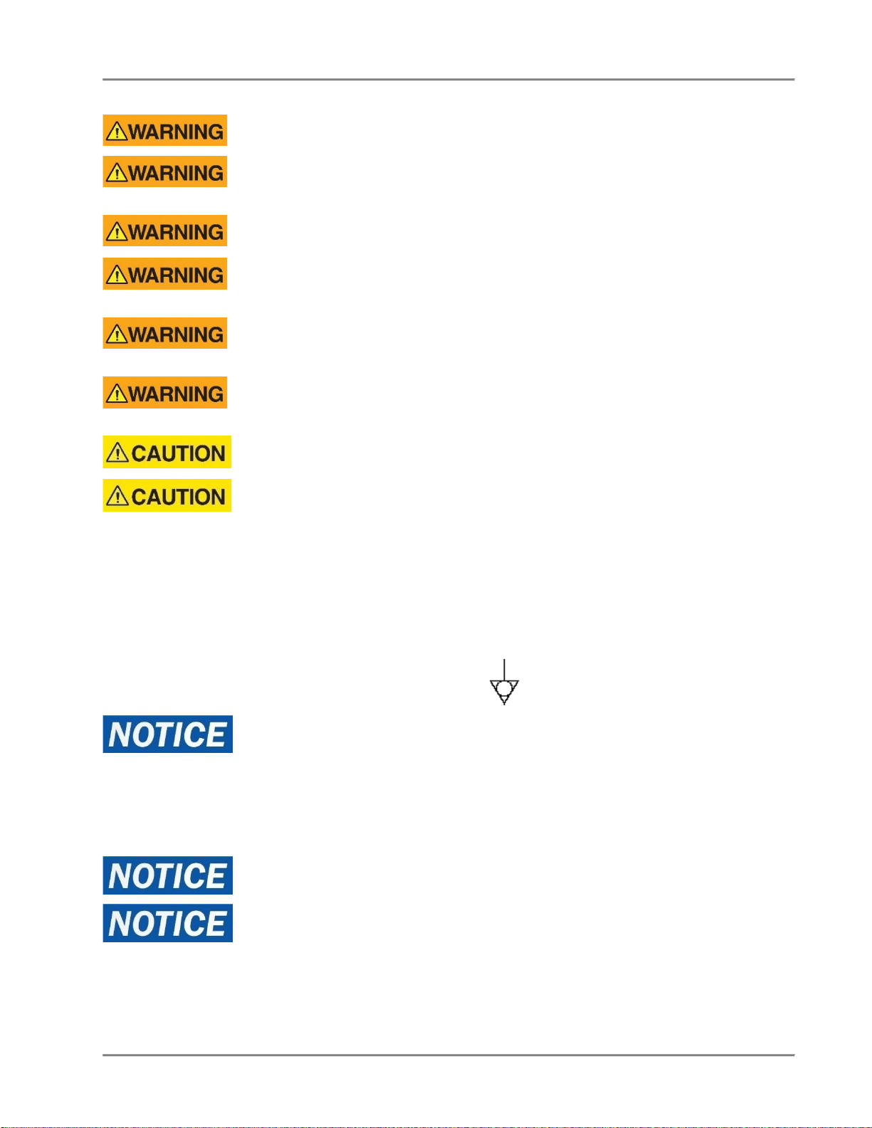
Do Not Store or Use Anything Flammable
Near the Fryer
Your pressure fryer is powered by either natural gas or LP gas. Do
not store or use gasoline or any flammable liquids or vapors near
this or any other appliance. Flammable materials will burn easily.
Letting any flammable liquid or vapor get too close to the fryer
could cause an explosion or fire. Serious injury could result.
Examples of flammables that you should not store near the fryer
are gasoline, paint, thinners or removers, gas tanks, and cleaning
materials.
Use Gas Safely-- Avoid Danger
Gas can be a dangerous fuel if not handled safely.
Make sure to ventilate the fryer properly. If the fryer is not properly
ventilated, carbon monoxide can be released around the fryer.
Asphyxiation or suffocation can occur if gas is not ventilated
properly.
Before using this appliance for the first time, contact your local gas
supplier for instructions about what to do if you smell gas. Post
those instructions somewhere near the fryer, so that everyone who
uses or works near the fryer knows what to do if they smell gas.
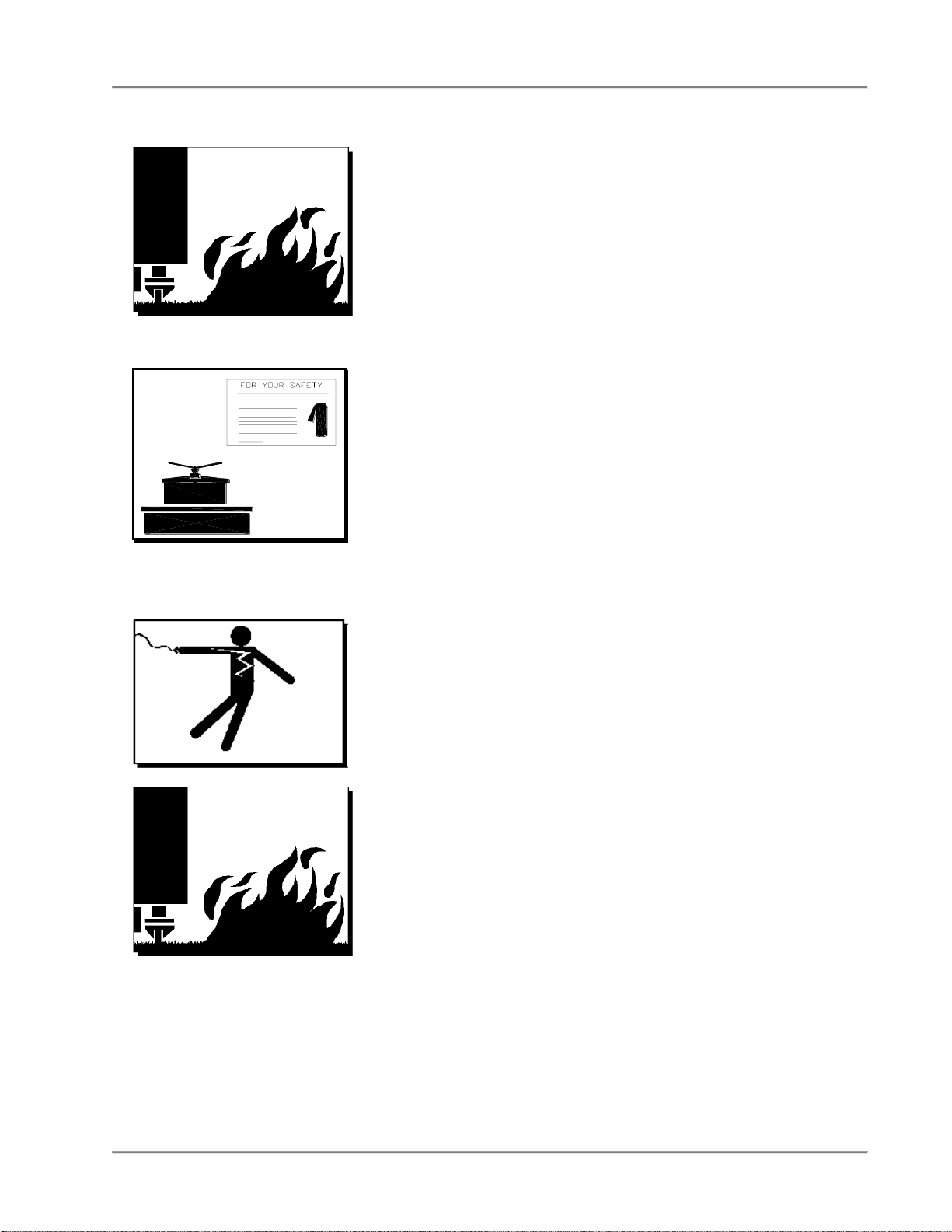
Beware of High Voltage
This equipment uses high voltage. Serious injury can occur if you
or any untrained or unauthorized person installs, services, or
repairs this equipment. Always Use an Authorized Service agent to
Service Your Equipment.
Noncombustible Floors Only
Make sure your floor is noncombustible. Do not operate your fryer
on floors that are wood, carpeted or have rubber mats.
• Placing your fryer on a combustible floor could cause a
fire. Serious injury could result.
• Examples of noncombustible floors where you can safely
place your fryer are concrete, tile, and ceramic.
Page 8
Gas Pressure Fryer Introduction
5
Keep the Area Around Your Fryer
Uncluttered
Make sure to keep the area around your fryer clear of any
obstacles.
Serious injury can occur if you trip or fall near the fryer. You could
be burned by hot shortening that splashes out of the fryer or by
falling against the hot metal of the fryer.
Keep the Floor Around Your Fryer Clean Of
Shortening
Make sure to keep the floor around your fryer clean of shortening
and other liquids.
Serious injury can occur if you slip near your fryer. You could be
burned by hot shortening that splashes out of the fryer or by falling
against the hot metal of the fryer.
Keep the Lid Closed When The Fryer Is Not
In Use
Hot shortening can splash if someone moves the fryer or bumps
into it. Serious injury can occur if hot shortening splashes out of the
fryer.
Do not lean, sit or stand on the fryer or perform any maintenance
or cleaning duties while the fryer or the shortening is hot. You
could be burned.
Keep the Casters Locked
To avoid spilling shortening, keep the casters locked. If any
shortening spills near your fryer, clean it up immediately.
Do Not Overfill the Fryer with Shortening
Hot shortening and steam may escape and burn you if you put too
much shortening in the fryer. Fill the fryer to the fill marks that are
inside the fryer pot. Heat the shortening.
Page 9
Gas Pressure Fryer Introduction
6
Do Not Let Any Water Get into The Fryer
Always remove excess moisture from food before placing it into the
fryer basket. Water will cause the hot shortening to spatter. You
could be burned.
Do Not Overload the Basket With Food
Hot shortening and steam may escape and burn you if you place
too much food in the basket.
Always Make Sure the Lid Hook Is Latched
When Closing The Fryer
To make sure the lid hook is latched properly, press down the lid
until the hook snaps shut. Hot shortening and steam can escape if
the lid hook is not latched properly. You could be burned.
Always Tighten the Spin Handle When
Closing The Fryer
Hot shortening and steam can escape if you do not tighten the spin
handle properly. You could be burned. Line up the orange knobs
on the fryer lid handle and the front hook when tightening.
Do Not Over-Tighten the Spin Handle
You could damage the fryer.
Wear Safe Clothing Appropriate To Your Job
Always wear your insulated mitts when handling the fryer basket or
touch any hot metal surfaces. You received a pair of insulated mitts
with your fryer. If you lose or damage your mitts, you can buy new
ones at your local restaurant equipment supply store or from your
local BKI Distributor.
Always wear non-skid shoes when working around the fryer or any
other equipment that uses shortening. Never wear loose clothing
such as neckties or scarves while operating your fryer. Keep loose
hair tied back or in a hair net while operating your fryer.
Always wear appropriate personal protection equipment during the
filtering process to guard against possible injury from hot oil.
Always wear appropriate personal protection equipment during the
boil-out process to guard against possible injury from hot cleaning
solution.
Page 10
Gas Pressure Fryer Introduction
7
Never Loosen the Spin Handle Until The
Pressure Gauge Is At Zero
Steam may escape suddenly if you loosen the spin handle before
the gauge is at zero. If steam escapes suddenly, you could be
burned.
After the pressure gauge is at zero, wait 5 seconds. Then loosen
the spin handle slowly to open the lid of the fryer. By doing this, the
steam will escape slowly and you will not be burned.
Seal the Safety Valve Properly
To seal the safety valve, lift the arm on the side of the valve. Then
release it. The valve should snap closed. Hot steam can escape
from the valve and you could be burned if you do not seal the valve
properly.
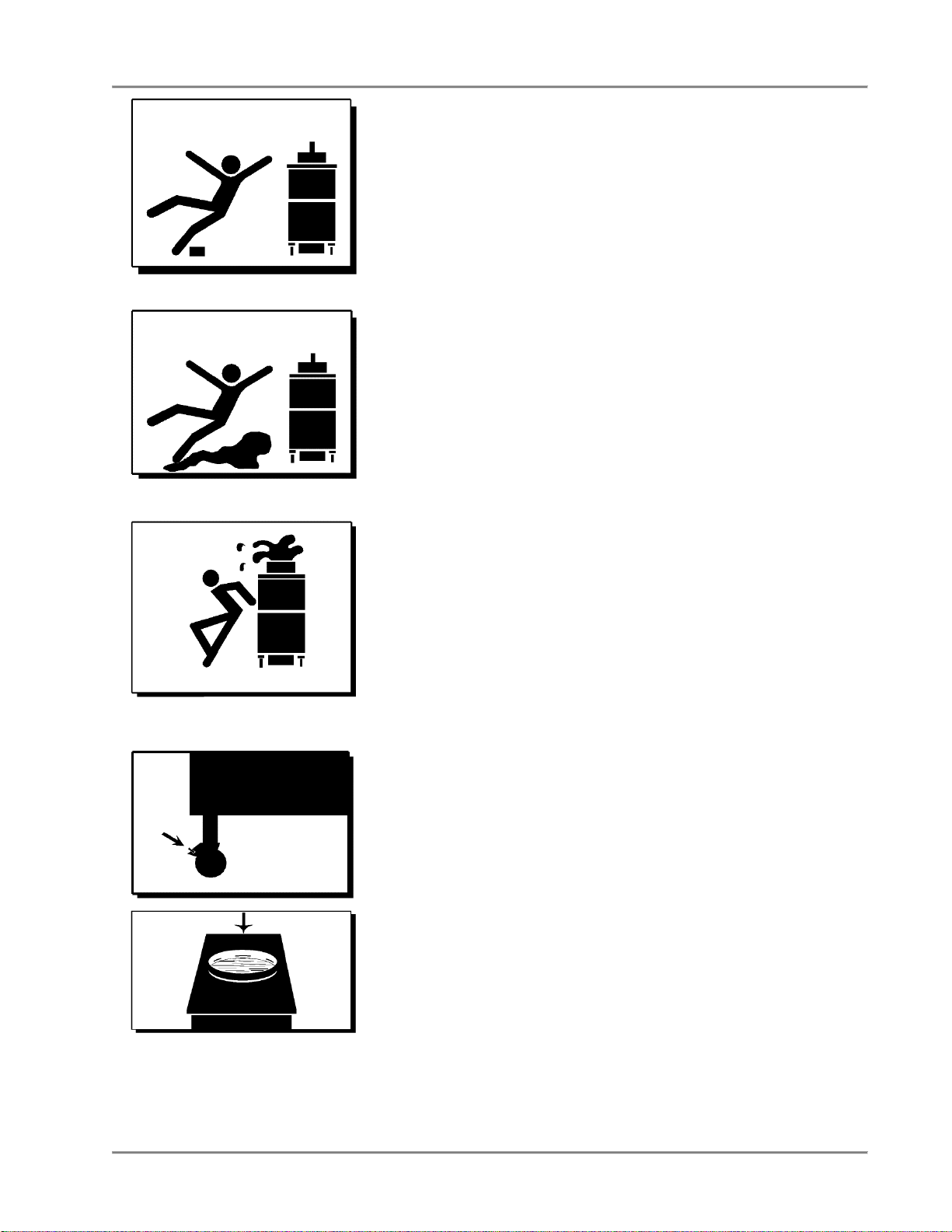
Keep Away From the Vent
Hot steam escapes from the vent continuously when you are using
your fryer. You could be burned if you get too close to the vent.
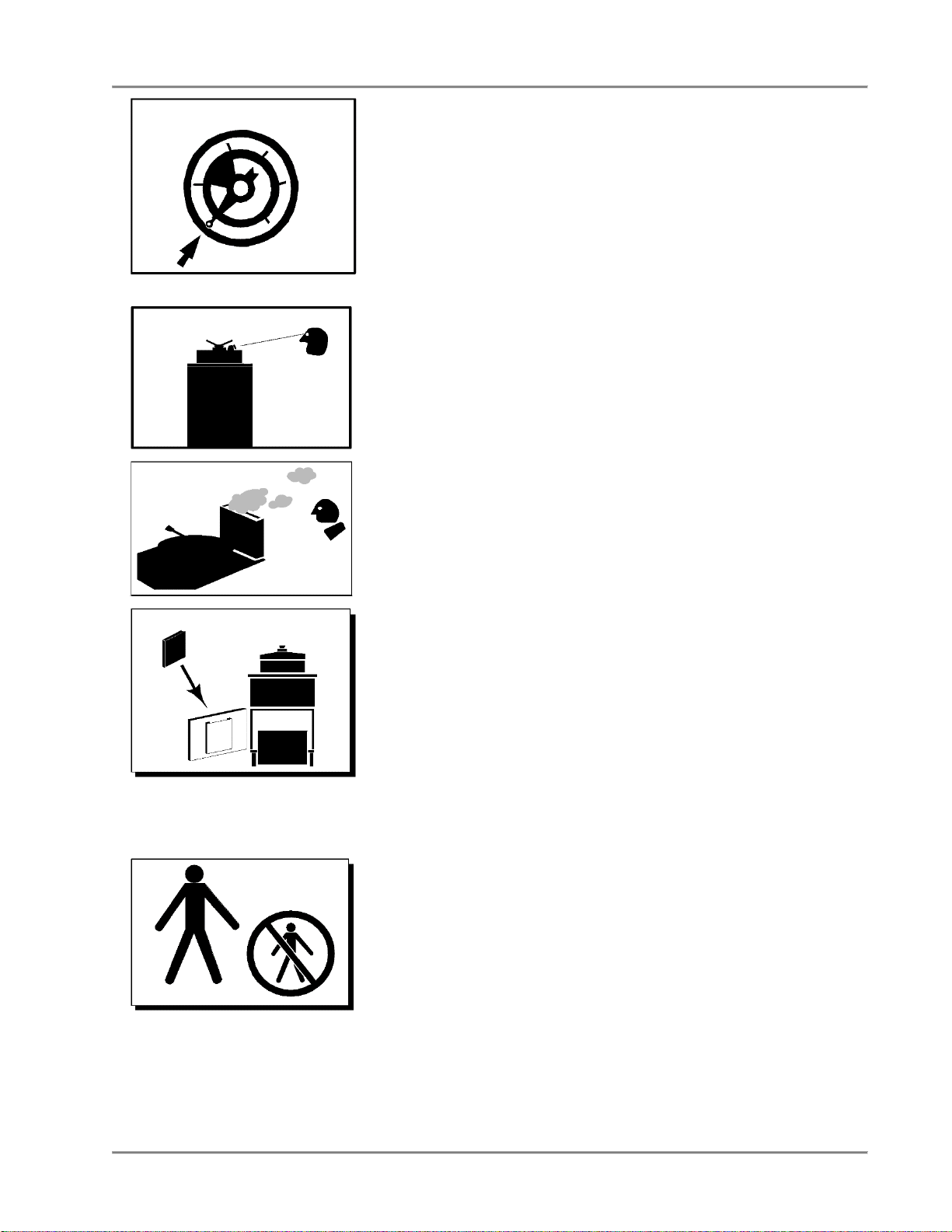
Keep this manual with the Equipment
This manual is an important part of your equipment. Always keep it
near for easy access.
If you need to replace this manual, contact:
BKI
Technical Services Department
2812 Grandview Drive
Simpsonville, S.C. 29680
Or call toll free: 1-800-927-6887
Outside the U.S., call 864-963-3471
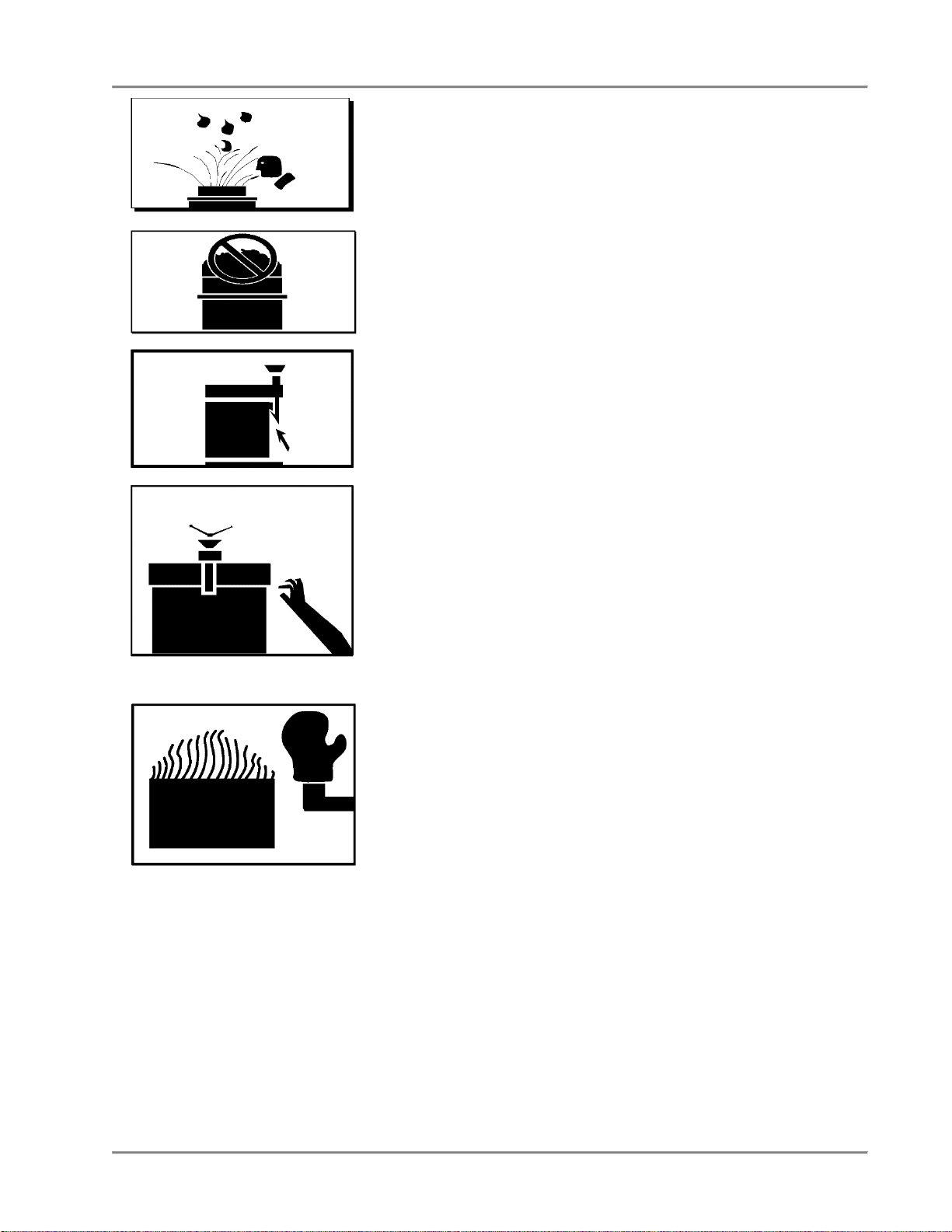
Protect Children
Keep children away from this equipment. Children may not
understand that this equipment is dangerous for them and others.
NEVER allow children to play near or operate your equipment.
Page 11
Gas Pressure Fryer Introduction
8
Keep Safety Labels Clean and in Good
Condition
Do not remove or cover any safety labels on your equipment. Keep
all safety labels clean and in good condition. Replace any
damaged or missing safety labels. Refer to the Safety Labels
section for illustration and location of safety labels on this unit.
If you need a new safety label, obtain the number of the specific
label illustrated on page Error! Bookmark not defined., then
contact:
BKI
Technical Services Department
2812 Grandview Drive
Simpsonville, S.C. 29680
Or call toll free: 1-800-927-6887
Outside the U.S., call 864-963-3471
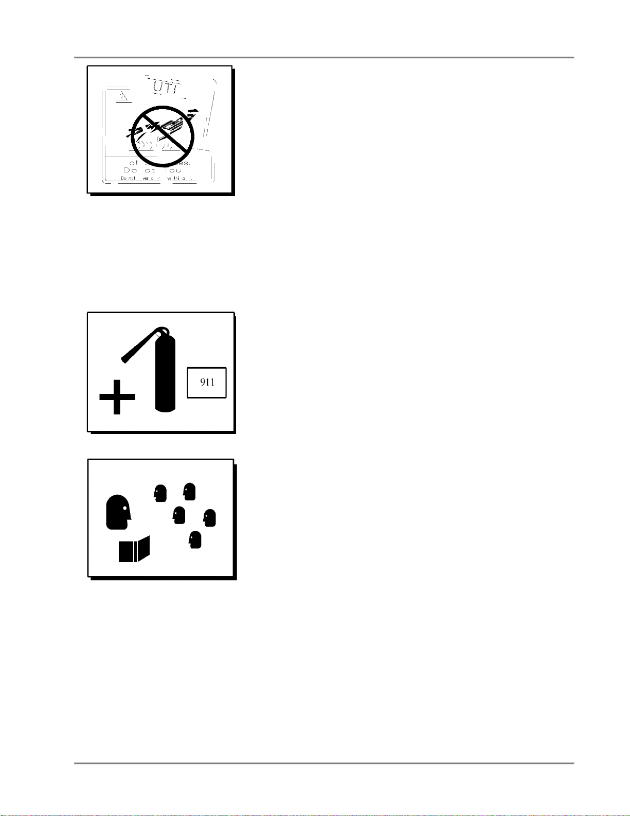
Be Prepared for Emergencies
Be prepared for fires, injuries, or other emergencies.
Keep a first aid kit and a fire extinguisher near the equipment. You
must use a 40-pound Type BC fire extinguisher and keep it within
25 feet of your equipment.
Keep emergency numbers for doctors, ambulance services,
hospitals, and the fire department near your telephone.
Know your responsibilities as an Employer
• Make certain your employees know how to operate the
equipment.
• Make certain your employees are aware of the safety
precautions on the equipment and in this manual.
• Make certain that you have thoroughly trained your employees
about operating the equipment safely.
• Make certain the equipment is in proper working condition. If
you make unauthorized modifications to the equipment, you will
reduce the function and safety of the equipment.
Page 12
Gas Pressure Fryer Introduction
9
Do Not Smoke Near The Fryer.
Electrical Grounding Instructions:
This appliance is equipped with a three-prong (grounding) plug for
your protection against shock hazard and should be plugged
directly into a properly grounded three-prong receptacle. Do not
cut or remove the grounding prong from this plug.
Page 13

Gas Pressure Fryer Installation
10
Installation
For installation information refer to Gas Pressure Fryer, MODEL FKG-TC, Installation and Operation Manual.
Page 14
Gas Pressure Fryer Operation
11
Operation
Start-Up (FKG-TC)
1. Turn fryer on by touching the ON button for 3 seconds.
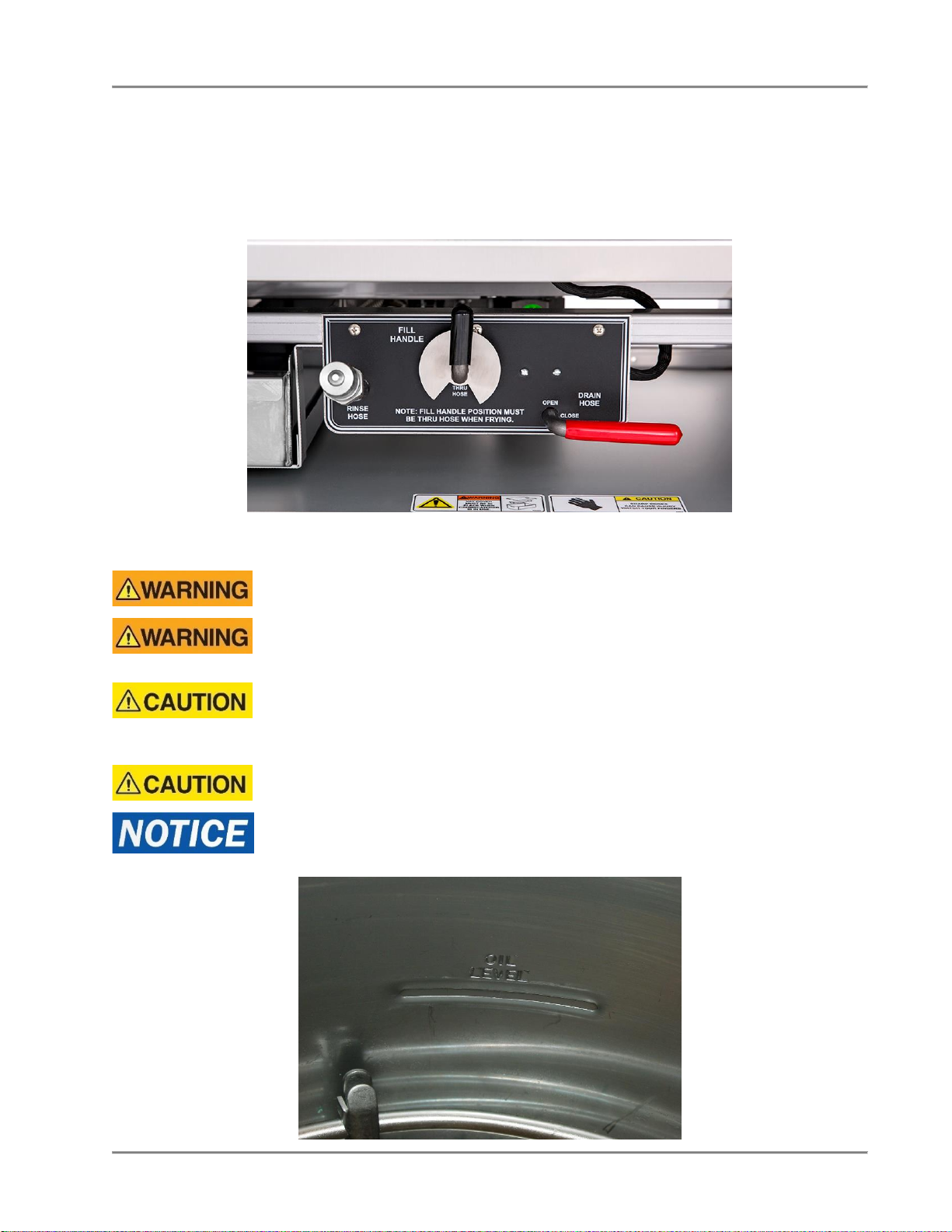
2. Make sure the main drain valve is closed.
3. Fill pot with shortening to about one inch below the mark.
Risk of fire exists if the oil level drops below the minimum oil level. The level of oil
within the pot must not fall below 5mm of the maximum oil level.
Use of oil/shortening older than the manufacturers recommendations for life of
the oil is prone to surge boiling and flash fires. Follow the oil manufacturers
guidelines for lifecycle of oil/shortening.
Overfilling the fryer pot with shortening could lead to serious injury. Ensure that
the fryer pot is filled with shortening only to the fill mark when shortening is hot.
Do not use any shortening other than what is specified in this manual and do not
overfill the fryer pot.
The fryer has a maximum temperature setting of 375º F/191º C. Do not use
oil/shortening with a flashpoint less than 554º F (290º C)
Use only high-quality shortening that has low moisture content, a high smoke
point and no additives.
Page 15
Gas Pressure Fryer Operation
12
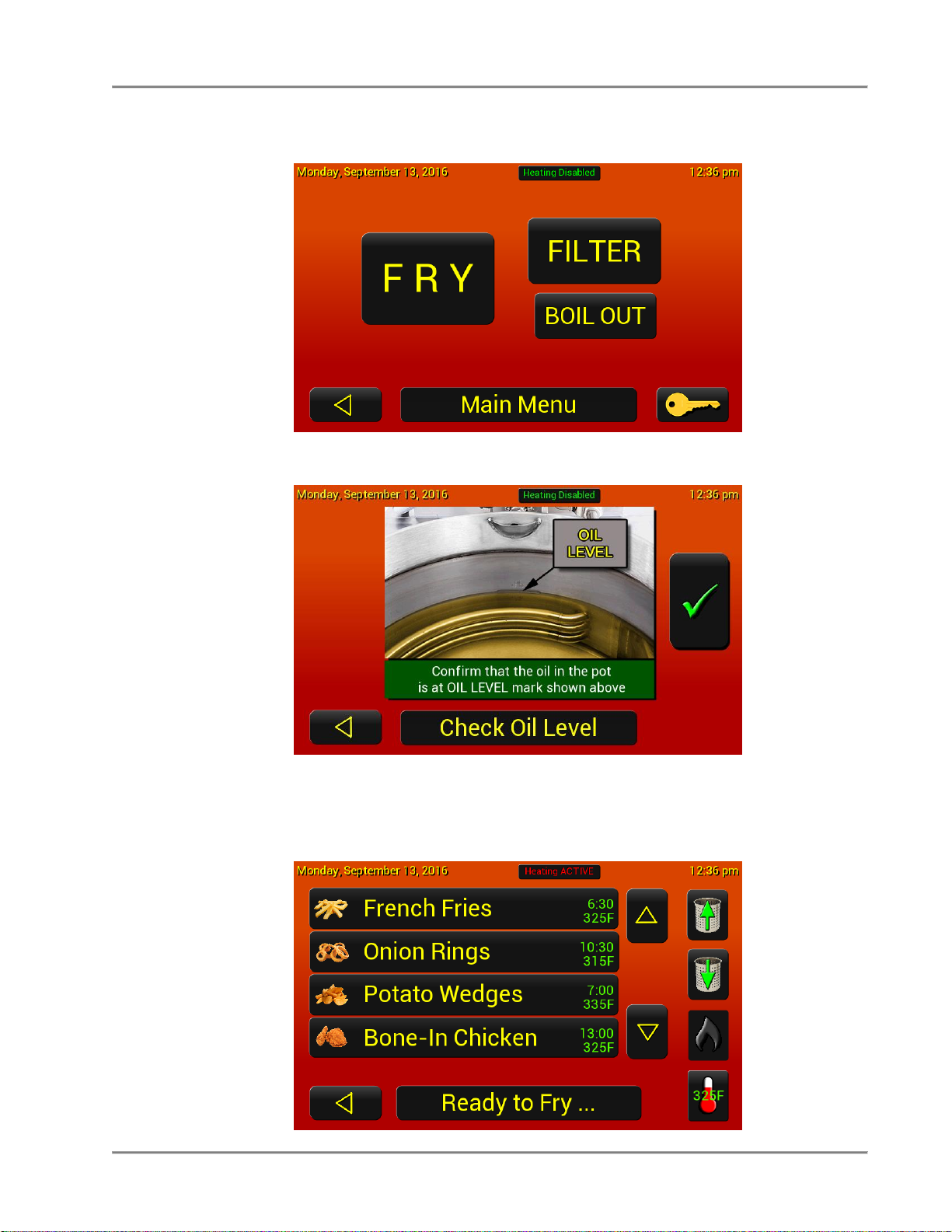
1. Once the fryer is filled with shortening, press the FRY button.
2. Confirm the oil level by pressing the green check mark.
3. The fryer will start heating up by going into a melt cycle. It will pulse the elements until the oil gets to
225° F (107° C) and then goes into heat mode until it reaches the setpoint temperature. The recipes
will be greyed out and inaccessible until the fryer reaches setpoint temperature. (If the burner does
not light and you get a Gas Alarm, see the Gas Alarm instructions in the Troubleshooting section.)
Page 16

Gas Pressure Fryer Operation
13
4. When the fryer is ready to cook the recipes will be activated.
IMPORTANT! Before the first cooking operation each day, stir the shortening freely while it is heating
to provide a balanced shortening temperature for excellent results with the first cooking. Failure to do
this can result in a crusty skin on the product surface with an undercooked product internally. In
addition, in some cases, failure to stir the shortening while it is initially heating may cause the HILIMIT safety device to disable the power due to a false overtemperature condition.
Page 17
Gas Pressure Fryer Operation
14
Product Programming
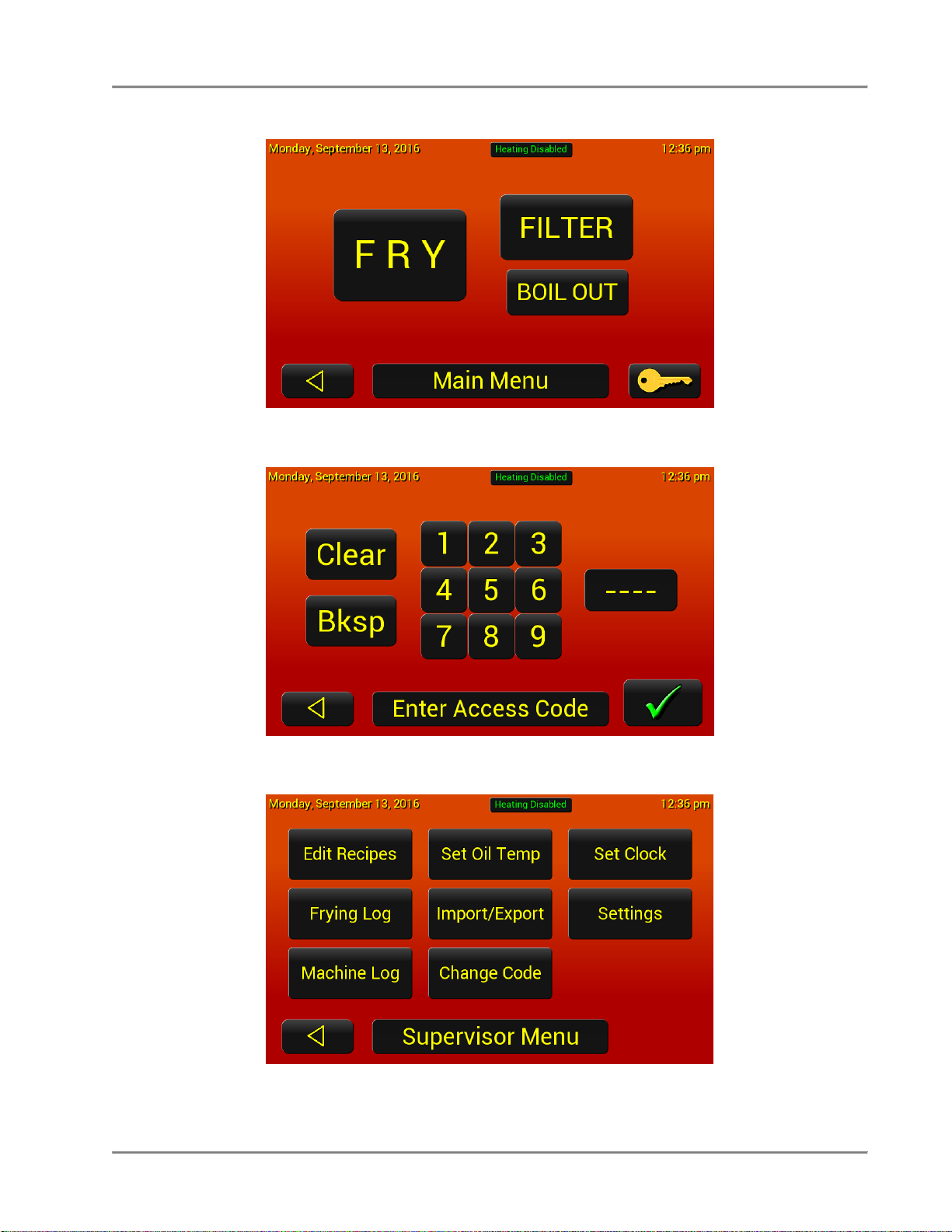
1. Press the Key button to get into the settings menus.
2. Enter code 1234 and then pres the green check mark.
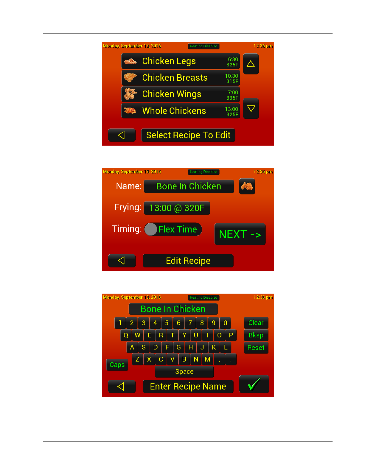
3. Select the Edit Recipe button
Page 18
Gas Pressure Fryer Operation
15
4. Select the Recipe that needs edited.
5. In the Edit Recipe screen the name, cook time, temperarture, timing type, & picture can be edited.
6. Select Name to change the name and press the green check mark to save.
Page 19
Gas Pressure Fryer Operation
16
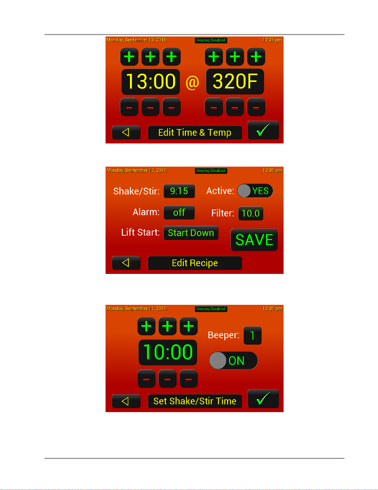
7. Select Frying to edit the time and temperature of the recipe. Press the green check mark to save.
8. Pressing the Next button will bring you to the second page where the shake/stir, alarm, if the program
is active, and the filter weight can be edited.
9. Press the Shake/Stir time to edit the time & numer of beeps. Press the green check mark to save.
Page 20

Gas Pressure Fryer Operation
17
10. Press the alarm time to edit the time. Press the green check mark to save.
11. Make sure the program is active and set the filter weight (1.0-12.0 by 0.5 increments, if using global
filtering).
12. When done, press the SAVE button to save the program.
13. If you want to cancel the recipe or accidently press the back button, the message above will display.
You can save by pressing the SAVE or cancel by pressing the back arrow.
Page 21

Gas Pressure Fryer Operation
18
Set Oil Temp
1. Get into the supervisor menu and select the Set Oil Temp button
2. Set the oil temperature to the desired ready to cook temperature between 250° F and 375° F.
3. Press the green check mark to save.
Page 22

Gas Pressure Fryer Operation
19
Set Clock
1. Get into the supervisor menu and select the Set Clock button
2. Set the date & time.
3. Press the green check mark to save.
Page 23

Gas Pressure Fryer Operation
20
Settings
1. Get into the supervisor menu and select the Settings button
2. Set the Beeper Volume (Low or High), Pattern (1, 2, or 3), the Filter Lockout* can be turned off & on,
the Filter Lockout Value can be set (2-20), and the Temperature Units can be set (C or F).
*The filter lockout is a global counter used to determine when to force filter. Set the total filter
value in settings and then in the recipes, the weight of each recipe can be set. (i.e. Fresh
breaded product can have a value of 3 and french fries a value of 1.) When the values of the
recipes cooked adds up to the global value (or over), the control will require a filter.
3. Press the green check mark to save.
Page 24

Gas Pressure Fryer Operation
21
Frying Log
1. Get into the supervisor menu and select the Frying Log button
2. The frying log will record the following events:
• Recipe Cooked with elapsed time and average temperature
• Basic Filter with filtering time, refill time, and number of pump lockouts
• Filter With Rinse Hose with filtering time, refill time, and number of pump lockouts
• Boil Out with heating time
3. Press the back button to exit.
Page 25

Gas Pressure Fryer Operation
22
Machine Log
4. Get into the supervisor menu and select the Machine Log button
5. The frying log will record the following events:
• Touchscreen Error
• Probe Error
• Nonvolatile Memory read, write, or data errors
• Factory Reset
• Touchscreen Calibration
• Configuration Change
• Password Error
• Password Reset
• Password Change
• Recipe Saved
• Recipes Imported
• Recipes Exported
• Configuration Import
• Configuration Export
• Frying Log Export
• Machine Log Export
• USB Drive read, write, and file open errors
• Touch Configuration Change
• Fryer Options Changed
• Firmware Update
6. Press the back button to exit.
Page 26

Gas Pressure Fryer Operation
23
Import/Export
1. Get into the supervisor menu and select the Import/Export button
2. Insert a USB drive.
3. Press the import/export recipes button to save the recipes to a USB or copy to the fryer.
Page 27

Gas Pressure Fryer Operation
24
1. To add up to 8 additional Recipe Icons, press the Import Icons button with the USB inserted.
2. Importable Image Requirements:
a. JPG images only, standard 24 bit color with any amount of image compression.
b. Recipe icons must be 64 pixels wide and 64 pixels tall.
c. The maximum file size is 54k bytes.
d. File names can be any combination of letters and numbers up to a maximum of 8 characters, the
extension must be “.jpg”. The name is case insensitive.
3. Touch the Find Files … button, the controller will look through the entire USB drive and find all jpg
files which are 64x64 pixels and below the maximum file size, displays the file name and image of the
first file found meeting those criteria, and shows the number of files found in the Find Files … button.
The 8 locations to the right will now be available, locations which already have an icon stored in them
will display the stored image. Use the up and down arrows to scroll through all the files the controller
found until the file wanted is displayed.
4. Select the location in which they want to store the icon, they can choose any of the eight locations
including those which are already in use, that location will be overwritten. The selected location
button turns green and the green check button is now available. Touching the green check button
stores the selected image into that location in the controller image format along with the name and
size of the file and the original jpg file data so it can be exported at some other time.
5. When the import is completed the controller chirps twice indicating that it has stored that icon. Select
other icon files and other icon locations and store as many of the images as desired.
6. Press the back button to exit.
Page 28

Gas Pressure Fryer Operation
25
1. To copy any or all 8 Recipe Icons, press the Export Icons button with the USB inserted.
2. The eight button on the left side display all the imported user icons. Select or deselect any of the 8
images to be exported just by touching the icon buttons. Touch once to select, touch again to
deselect. The Select All button can be used tol select all imported icons.
3. Touch the green check button to export all of the selected icons with their original file names and data
to the USB drive. NOTE: Files already on the flash drive which have the same name as the original
files will be overwritten with the stored image data.
4. Press the back button to exit.
Page 29

Gas Pressure Fryer Operation
26
Change Code
1. Get into the supervisor menu and select the Change Code button
2. Enter the new 4 digit access code. We recommend an easy to remember number, like the store
number.
3. Press the green check mark to save.
Page 30

Gas Pressure Fryer Operation
27
System I/O
1. Enter code 5142 and then pres the green check mark to get into the technician menus.
2. Select the MORE button.
3. Select the System I/O button.
Page 31

Gas Pressure Fryer Operation
28
4. The System I/O let you see which out puts are open or closed and the oil temperature. The text in
the yellow are the state of the output.
The bottom half of the screen are inputs and the individual components can be turned off and on by
pressing the assiciated button. This can be used to aid in the troubleshooting of the components.
Do not turn on Heat [K1][DO1] without the elements being fully covered with oil
or water. Damage to the elements and/or fryer may occur.
Page 32

Gas Pressure Fryer Operation
29
Cap Touch
1. Select the Cap Touch button to configure and callibrate the touch screen.
2. The screen sensitivity can be adjusted by using the +/- buttons. Also, the glass thickness can be
changed to fine tune the sensitivity.
3. To calibrate the screen, press the Calibrate Touch button and follow the instructions on the screen.
Page 33

Gas Pressure Fryer Operation
30
Options
1. Select the Options button to configure the control for the type of fryer you have.
2. The “Outputs” & “Inputs” indicates what is active (green) and inactive (red).
3. Set the fryer up using the HEAT, LID SOL, LIFT, & MODEL buttons.
a. HEAT: Elec or Gas
b. LID SOL: On (pressure fryer) or Off
c. LIFT: None or Manual (lift assist) or Auto (auto lift fryer)
d. MODEL: Type in the model of fryer
4. Press the green check mark to save.
Page 34

Gas Pressure Fryer Operation
31
Screen
1. Select the Screen button to configure the background color and the spalsh screen logo.
2. Insert the USB flash drive containing the files if you want to import images.
3. Changing the Background - The Background button has the following options, touch the button to
toggle between them and see how they look:
a. BKI Image – Displays the standard BKI background image.
b. Imported – Displays the imported image if present. Touch the [Import Background] button
and the controller imports the BGROUND.RAW image and displays it. The progress bar will
show the importing process.
c. Black – Displays a solid black background
d. Dk Grey – Displays a dark grey background
e. Dk Red – Displays a dark red background and screen title bar
f. Dk Green - Displays a dark green background and screen title bar
g. Dk Blue - Displays a dark blur background and screen title bar
h. Gradient – Displays an orange to red gradient background
4. Keep touching the Background button and it will wrap around to the beginning of the list.
5. Changing the Splash Logo - The Splash Logo button has the following options:
a. BKI Logo – Displays the standard BKI logo in the splash screen
b. Imported – Displays the imported logo in the splash screen
Page 35

Gas Pressure Fryer Operation
32
6. Before importing the logo you must set the image width and height. If the width and height shown in
the button below the Import Logo button are not correct touch the [W x H] button and the following
window appears:
7. Use the [+] and [-] buttons to set the image width and height and then touch the green check mark
button to save the new values and return to the Screen Settings window.
8. Once the image size has been set touch the Import Logo button and the LOGO.RAW file will be
imported and stored along with the image size. The progress bar will show the importing of the file
data.
9. Press the green check mark to save.
Page 36

Gas Pressure Fryer Maintenance
33
Maintenance
Failure to comply with the maintenance below could result in a serious accident.
Do not over-tighten the spindle assembly. (Only tighten to hold pressure.)
Your fryer will need periodic maintenance and servicing. We strongly suggest that
you use only a service company that is authorized by BKI to do this work.
The restraining device must always be connected when the appliance is in service.
Disconnect for movement, such as servicing or cleaning. Reconnect the restraint
when fryer has been returned to its normal position.
The FKG appliance is not intended to be cleaned with a water jet.
Scheduled Maintenance
Use the following table to help manage scheduled maintenance activities.
FREQUENCY
PERFORMED BY
PART
ACTIVITY
Each Fry Cycle
User
Pressure Gauge
Check for proper display of cooking vat
pressure. Contact authorized BKI service
agent if adjustment or replacement is
required.
User
Lid Gasket
Check for unusual wear such as cracks
and deformation, and pressure leaks.
Contact authorized BKI service agent if
adjustment or replacement is required.
Daily
User
Dead Weight
Assembly
Clean weight and orifices daily and check
for wear.
User
Filter Pad
Replace filter pad. Refer to the procedure
in this manual.
User
Condensation Pan
Remove and drain.
User
Filter system
Filter the shortening using the procedure
in this manual.
Weekly
User
Safety Pop Valve
Check for release of pressure and proper
seal. Refer to the procedure in this
manual.
User
Fryer Pot
Perform the boil-out procedure in this
manual.
Every 6 Months
Authorized BKI
service agent
Acme Screw and
Nut
Check for wear on the threads.
Authorized BKI
service agent
Solenoid Valve
Check that the valve is holding and
releasing pressure when the timer or
computer activates it.
Authorized BKI
service agent
Hook, Catch, Spring
Check for wear and ease of operation.
Authorized BKI
service agent
Connections,
Fittings
Check for leakage while oil is pumping.
Page 37

Gas Pressure Fryer Maintenance
34
FREQUENCY
PERFORMED BY
PART
ACTIVITY
Authorized BKI
service agent
Fryer Pot
Fittings/Connections
Check for leakage around fry pot top deck
and fittings (heaters, hi-limit, thermostat,
etc.).
Safety Pop Valve Procedure
The safety pop valve should be blown under pressure periodically to prevent the seat from sticking.
Failure to use the insulated mitts will result in injury. Always use the insulated mitts
when handling the arm on the safety valve.
1. After the pressure is up during a cooking cycle, use the insulated glove to lift the arm on the edge of
the safety valve and let some steam escape. This will clean the valve.
2. Release the lever on the valve, and let it slam shut to seal the valve.
Page 38

Gas Pressure Fryer
35
Troubleshooting
Refer to the table below for troubleshooting information.
Problem
Cause
Possible Solution
Pressure Loss or Not
Releasing Pressure
Dead Weight Valve Leaking
Clean the weight and orifice. If
problems persist, contact an authorized
BKI service agent for corrective action.
Lid Gasket Leaking
Contact an authorized BKI service
agent for corrective action.
Solenoid Valve Leaking or
Stuck
After a period of time, it is possible that
the valve seat and/or plunger may stick
or wear. Activate the valve by starting a
cook cycle. You should hear a solid
metallic CLICK sound from the solenoid
valve. If you should hear no sound (or a
slow BUZZING CLICK), contact an
authorized BKI service agent for
corrective action.
Safety Valve not seating
Contact an authorized BKI service
agent for corrective action.
Shortening Heating Too
Slowly
Gas pressure is low or isn’t
adjusted properly
Contact an authorized BKI service
agent for corrective action.
Bad thermostat or loose
wires
Contact an authorized BKI service
agent for corrective action.
Filter System Not Working
Uncertain
Press the hi-limit reset button under
control panel. If problems persist,
contact an authorized BKI service
agent for corrective action.
Connections not tight
Tighten the connections. If problems
persist, contact an authorized BKI
service agent for corrective action.
Filter valve not open
Contact an authorized BKI service
agent for corrective action.
Filter paper on screen
clogged with crumbs
Change filter paper. If problems persist,
contact an authorized BKI service
agent for corrective action.
Motor hums, but does not
pump
Check for clogged pump. If problems
persist, contact an authorized BKI
service agent for corrective action.
Motor and pump coupling
worn
Contact an authorized BKI service
agent for corrective action.
No power to control panel
Make sure drain valve is completely
closed. If problems persist, contact an
authorized BKI service agent for
corrective action.
Computer Hangs
Computer malfunction.
Turn the power OFF then back ON. If
problems persist, contact an authorized
BKI service agent for corrective action.
Page 39

Gas Pressure Fryer
36
Gas Alarm
If the fryer tries 3 times to light the burner without success the gas control system will lock out and a Gas
Alarm will pop up on the screen. Press the green RESET button to reset the gas control system and try to
light again. If the problem persists, contact an authorized BKI service agent for corrective action.
Filter Pump Reset
If the filter pump overheats a PUMP TOO HOT alert will pop up and a timer will start to count up.
Page 40

Gas Pressure Fryer
37
Once the pump has cooled, the screen will indicate that the pump is ready. Press the green Check Mark to
start the pump back up.
Page 41

Gas Pressure Fryer Replacement Parts
Description
Assembly #
Figure #
Table #
DEAD WEIGHT ASSEMBLY
AN19312300
Figure 1
Table 1
SOLENOID VALVE
AN19312400
Figure 2
Table 2
DOOR ASSEMBLY
AB19311700
Figure 3
Table 3
LID/TOP ASSEMBLY
SB1992S
Figure 4
Table 4
OIL VAT ASSEMBLY
AN19313000
Figure 5
Table 5
QUICK DISCONNECT ASSEMBLY
AN19103300
SB1997S
Figure 6
Table 6
COMPONENT PANEL FKG-TC
AN19317600
Figure 7
Table 7
FRONT PANEL FKG-TC
AB19112700
Figure 8
Table 8
GAS SYSTEM ASSEMBLY
N/A
Figure 9
Table 9
DRAIN/MOTOR/PIPING ASSEMBLY
N/A
Figure 10
Table 10
Replacement Parts
Use the information in this section to identify replacement parts. To order replacement parts, call your local
BKI sales and service representative. Before calling, please note the serial number, model number, gas type
and voltage on the rating tag affixed to the unit.
Assemblies
38
Page 42

Gas Pressure Fryer Replacement Parts
ITEM #
PART #
QTY
DESCRIPTION
1
FT0396
1
PIPE, DEAD WT TO BAFFLE BOX
2
FT0414
1
NIPPLE, 1/2" x 3 3/4", SS SCH 80
3
O0001
1
ORIFICE, SS
4
O0002
1
GASKET, O-RING #2-222
5
PV0001
1
VALVE, POP SAFETY 1321148
6
FT0066
1
ELL, REDUCER 3/4 X 1/2 90 DEG
7
FT0235
1
NIPPLE, 1/2 X C SS
8
FT0190
1
ELL, STREET 1/4 90 DEG CP
9
FT0084
1
COUPLING, BRASS 1/4
10
FT0563
1
FITTING, COMPRESSION ¾”
11
FT0067
1
BUSHING, C110JO 3/4 X 1/2 CP
12
FT0234
1
NIPPLE, 1/4 X 1 1/2 SS 304
13
C0657
1
COVER, DEAD WEIGHT VALVE FKM
14
B0969
1
BODY, DEAD WEIGHT VALVE FKM
15
W0201
1
WEIGHT, VALVE FKM 12#
16
G0136
1
GAUGE, PRESSURE 30 PSI
Figure 1. Dead Weight Assembly
Table 1. Dead Weight Assembly Parts
39
Page 43

Gas Pressure Fryer Replacement Parts
ITEM #
PART #
QTY
DESCRIPTION
1
FT0249
1
CONNECTOR, 3/8 STR FLEX LIQUIDTITE
2
FT0414
1
NIPPLE, 1/2" x 3 3/4", SS SCH 80
3
SV0004
1
VALVE, SOLENOID HV-214-761-2 120V
4
FT0563
1
FITTING, COMPRESSION ¾”
Figure 2. Solenoid Valve Assembly
Table 2. Solenoid Valve Assembly Parts
Figure 3. Door Assembly Parts
40
Page 44

Gas Pressure Fryer Replacement Parts
ITEM #
PART #
QTY
DESCRIPTION
1
F0083
2
THREAD INSERT 10-24 STEEL
2
ST0013
1
BRACKET, BRUSH HOLDER FKM, LPF,LGF
3
H0010
2
HINGE, LH PIN HALF
4
N0059
1
DECAL, SMALL BRUSH/
5
N0165
1
DECAL, NOTICE LOST MANUAL
6
N0527
1
DECAL, SAFETY INSTR FRYERS
7
N0175
1
DECAL, SLIPPING ADMONITIONS
8
N0176
1
DECAL, INSTR & SAFETY MANUAL
9
P0022
1
HANDLE, PULL SS P60-1010
10
RIV172
3
RIVET, 1/8 X 1/4 CS PLT POP
11
SB1951
1
INSIDE DOOR POCKET/MAGNET WELD FKM
12
SCR008
6
SCREW, 10 X 1/2 PHIL TRUSS HD
13
SCR383
2
SCREW, 10-24 X 1/2" PHIL TRUSS HD
14
WFKMA178
1
DOOR, FRYER OUTSIDE WELD
15
N0153
1
DECAL, FKM WARNING ACME SCREW
16
H0009
1
HINGE, DOOR,RH,PIN SIDE FRY.DOORS
Table 3. Door Assembly Parts
Figure 4. Lid/Top (sheet 1 of 4)
41
Page 45

Gas Pressure Fryer Replacement Parts
42
Page 46

Gas Pressure Fryer Replacement Parts
43
Figure 6. Lid/Top (Sheet 2 of 4)
Page 47

Gas Pressure Fryer Replacement Parts
44
Figure 6. Lid/Top (Sheet 3 of 4)
Page 48

Gas Pressure Fryer Replacement Parts
45
Figure 6. Lid/Top (Sheet 4 of 4)
Page 49

Gas Pressure Fryer Replacement Parts
ITEM #
PART #
QTY
DESCRIPTION
Figure 6 (sheet 1)
SB1992S
LID/TOP
Figure 6 (sheet 2)
SB3481
1
HANDLE ASSY, SPIN
1
FT0332
3
STUD, 5.5” TIGHTEN DN HN
2
K0202
2
KNOB, BLACK
3
K0020
1
HUB, TIGHTEN DOWN
4
K0203
1
KNOB, ORANGE
Figure 6 (sheet 3)
AB19103900
1
ARM ASSY, FKM
1
A0120
1
ARM COMPLETE FKM LGF
2
H0155
1
HANDLE, BLK DELRIN FKM LPF LGF
3
P0094
1
PIN, HOOK FKM, LPF, LGF
4
H0024
1
HOOK, LID 1018 ALLOY
5
K0203
1
KNOB, ORANGE
6
N0160
1
DECAL, WARNING BEFORE USING
7
NUT128
2
NUT, 5/16-18 SS 18-8 CAP
8
S0091
1
SPRING, HOOK LGF LPF FKM
9
SCR122
2
SCREW, 1/4-20 X 1/2 FLAT HD
10
SCR259
2
SCREW, 1/4-20 X 1/2 PHIL RD HD
11
TB0020
1
BUSHING, BRONZE 1"
12
H0156
2
HANDLE SIDE FOR H0155 FKM LPF LGF
13
WSH045
2
WASHER, 5/16 LOCK ZINC PLTD
14
WSH102
2
WASHER, 1/4 INT LOCK
15
FT0407
1
PLUG, HOLE 3/8" SHORT PRONG
16
F0026
1
ROLL PIN, 5/32 X 3/4
Figure 6 (sheet 4)
SB1989
1
LID LOCKING ASSY W/INSERT FKM
1
F0353
1
PIN, LOCKING FKM LGF LPF
2
G0016
1
GASKET, FKM LID BONDED SILICON
3
S0155
1
SPRING, LOCKING PIN W/LID INSERT
4
B0857
1
BUSHING, BRONZE 3/8X9/16X5/8
5
P0115
1
LID INSERT, FKM
6
FK0010
1
LID, FKM CAST ALUM
7
C0674 *
1
LID COVER AND ARM GUIDE FKM
8
F0107
1
LOCK KEY PIN, FRYERS
9
FKMA016
1
PIN, HINGE
10
FKMA152
1
KEY, TIGHTEN DOWN SCREW
11
FKMA201
1
PLATE, TIGHTEN DOWN FKM
12
FT0049
2
COLLAR, 1/2" SET BRIGHT
13
N0153 *
1
DECAL, FKM WARNING ACME SCREW
14
N0345 *
1
DECAL, HOOK LID INSTRUCTIONS
15
SCR383
2
SCREW, 10-24 X 1/2" PHIL TRUSS HD
16
SCR176
2
SCREW, 8-32 X 3/8 SLOT BINDING
17
SCR178
1
SCREW, 5/16-18 X 1 FLAT HD
18
TB0021
1
TIGHTEN DOWN BASE COLD ROLLED
19
TC0003
1
COLLAR, THREADED SHAFT
20
TC0005
1
COLLAR, LOCKING RING
21
TS0010
1
SCREW, TIGHTEN DOWN
22
S0071
1
SPRING, TORSION
23
LZ0107
1
PLATE, LID FOR LOCKING DEVICE
Table 4. Lid/Top Parts
* - These parts constitute Lid Cover Assembly, AN1910840S.
46
Page 50

Gas Pressure Fryer Replacement Parts
47
Figure 5. Oil Vat Assembly
2
7
5
3
4
8
6
10
9
1
11
13
12
12
Table 5. Oil Vat Assembly Parts
Page 51

Gas Pressure Fryer Replacement Parts
ITEM #
PART #
QTY
DESCRIPTION
AN19313000
1
FILTER SCREEN ASSY,FKG
1
WB16010600
1
WELDMENT, FILTER VAT QUICK DISCONNECT
2
WB16022100
1
WELDMENT, FILTER TUBE, BLF
3
FS0002
1
FILTER SCREEN, INTERCEPTOR
4
FS0003
1
FILTER SCREEN, TOP
5
FS0001
1
FILTER SCREEN, BOTTOM
6
SB7659
1
FILTER SCREEN FITTING SPOTWELD
7
FC0004
1
NUT SCREEN RETAINING FKM-F & FKM-FC
8
O0013
1
O-RING, FLUOROCARBON V680-70
9
SCR344
1
SCREW, SET, SOC, 8-32 X 1/4
10
SB7675
1
CRUMB BASKET WELD, LG VAT ASSY
11
FB19312904
1
COVER, FILTER VAT, SHEET METAL FRAME
12
N0395
1
DECAL, VAT COVER SAFETY WARN
13
N0694
2
DECAL, CAUTION, SHARP EDGES
ITEM #
PART #
QTY
DESCRIPTION
1
B0996
1
BALL, 11/16" STEEL BEARING
2
FT0429
1
QUICK DISCONNECT, PUMP SIDE
3
FT0500
1
QUICK DISCONNECT, VAT SIDE
4
FT0536*
1
COUPLING, 5/8 45¦ FLARE TO
5
O0013
2
O-RING, FLUOROCARBON V680-70
6
O0014
1
O-RING, PARKER #2-124 LARGE
7
S0138
1
SPRING, FOR QUICK DISCONNECT
8
SCR453*
2
SCREW, #10 24X3/8" WASHERED
Figure 6. Quick Disconnect Assembly
Table 6. Quick Disconnect Assembly Parts
* - Not included with SB1997S
48
Page 52

Gas Pressure Fryer Replacement Parts
49
Figure 7. Component Panel FKG-TC
1
3
18
25
16
15
21
8
17
7
22
10
5
12
4
6
9
11
11
13
2
20
19
14
23
13
26
24
27
28
Page 53

Gas Pressure Fryer Replacement Parts
ITEM #
PART #
QTY
DESCRIPTION
1
FB16004210
1
RELAY PANEL, BLF/FKM
2
FB16201910
1
BRACKET, FUSE HOLDER, FKG/BLG
3
CP0110
1
MOTOR CONTROL BOARD, COMBUSTION BLOWER
4
SP0047
4
SPACER, .250 OD x .312 L x #6 ID, NYLON
5
SCR118
6
SCREW, 6-32 X 5/8 SLTD RD ZINC PLATED
6
WSH089
10
WASHER, #6 INT LOCK ZINC PLATED
7
NUT048
10
NUT, 6-32 HEX ZINC PLTD
8
FH0001
1
FUSE HOLDER, 15A 300V HPF-EE
9
T0036
1
THERMOSTAT, HI LIMIT 540 DEG
10
SCR006
11
SCREW, 8 X ½ PHIL PAN TYPE “B” NKL PLTD
11
TF0005
2
TRANSFORMER, 120-24V LGF
12
SCR138
4
SCREW, #10 X ½” PHIL TRUSS HD
13
R0196
2
RELAY, DPDT 220/240V FLANGE MOUNT
14
FU004UK
2
FUSEHOLDER, 5 x 20 mm, PANEL MOUNT, 0.188 TAB TERMINALS
15
F0158
1
BUSHING, BLK ½ HEYCO SNAP
16
F0154
1
BUSHING, BLACK 1-3/16 HEYCO SNAP
17
FT0080
1
CONNECTOR, BOX #7483, 1”
18
F0097
1
FUSE, 15A 300V SC15 TIME DELAY
19
F0177
1
FUSE, HOUNO 3.15A, #061417
20
F0417
1
FUSE, 5 x 20mm, 1A 250V, TIME DELAY
21
F0342
2
CLAMP, CABLE 3/16”
22
RIV180
2
RIVET, 1/8” SS (0.063-0.125)
23
CP0118
1
BOARD, POWER RELAY, I/O
24
SP0013
4
SPACER, FOR #8 X 1/2" LG.
25
SCR194
4
SCREW, 6-32 X 1 SLTD RD
26
R0197
1
RELAY, DPDT, 110/120V, FLANGE MOUNT
27
USB001
1
CORD, USB, WATERPROOF, PANEL MOUNT, FEMALE-MALE, 0.5M LONG
28
USB002
1
CAP, USB
29*
MA19101700
1
CONDUIT, 1"" FLEX 21.50
30*
F0315
2
BUSHING, CONDUIT 1" PLASTIC
31*
S0063
1
SPRING GUARD, 6 ½” FRYERS
32*
HF0013
2
CLAMP, HOSE, #62M10
Table 7. Component Panel FKG-TC Parts
* Not Shown
50
Page 54

Gas Pressure Fryer Replacement Parts
3
4
7
6
1
2
5
8
ITEM #
PART #
QTY
DESCRIPTION
1
FB19112600
1
STUD ASSEMBLY, CONTROL PANEL, TOUCH SCREEN
2
CP0117
1
CONTROLLER, TOUCH SCREEN, FRYER
3
S0712
1
SWITCH, CAPACITIVE TOUCH, 2-BUTTON, ON/OFF
4
NUT048
8
NUT, 6-32 HEX ZINC PLTD
5
WSH089
8
WASHER, #6 INT LOCK ZINC PLATED
6
SP0052
4
SPACER, 5/16 OD, 1/4 L, #10 ID ALUMINUM
7
SP0013
4
SPACER, FOR #8 X 1/2" LG.
8
WSH271
4
WASHER, #8 FLAT S/S
9*
N0702
1
DECAL, CONTROL PANEL, FRYER, TOUCH SCREEN
10*
T0184
1
PROBE, TEMPERATURE, 100 OHM RTD
11*
FT0286
1
THERMOCOUPLE FITTING W/FERRULE & NUT
12*
FT0287
1
BUSHING, REDUCING 3/8" x 1/8"
Figure 8. Front Panel FKG-TC
Table 8. Front Panel FKG-TC Parts
* Not Shown
51
Page 55

Gas Pressure Fryer Replacement Parts
ITEM #
PART #
QTY
DESCRIPTION
1
G0327
2
GASKET, BURNER & FLUE, FKG/BLG
2
WB19306600
1
WELDMENT, BLOWER DUCT (STRAIGHT), FKG/BLG
3
2015768
1
GASKET, COMBUSTION BLOWER
4
AB19310900
1
ASSEMBLY, COMBUSTION BLOWER, FKG/BLG
5
7020204
1
VALVE, GAS, FKG/BLG
6
2015652
1
FITTING, GAS VALVE TO ORIFICE
7
2019975
1
FITTING, GAS VALVE TO GAS CONNECTION
8
7070142
2
GASKET, ALUMINUM WASHER
9
O0029
1
ORIFICE, NATURAL GAS, 3.8 MM
O0030
1
ORIFICE, LP GAS, 3.2 MM
10
S0097
1
SWITCH, VACUUM 0.14"W.C. FH
11
FB19315900
1
ASSEMBLY, GAS BURNER, 5.00”, FKG/BLG
12
I0511
1
IGNITER, ELECTRODE
13
I0512
2
INSULATOR, BOOT, STRAIGHT SPARK PLUG
14
G0328
1
GASKET, IGNITER, FKG/BLG
15
7020217
1
IGNITION MODULE, IGNITION BOOST
16
WSH248
6
WASHERED LOCKNUT, 1/4-20 ZINC EXTERNAL TOOTH
17
NUT276
2
NUT, #8-32, KEPS, ZINC PLATED STL
18
SCR426
4
SCREW, 10-24 X 3/4, HEX CAP, SS
19
NUT286
6
NUT, #10-24 KEPS, ZINC PLATED STL
20
H0218
1
HOSE, GAS LINE, FKG/BLG
21
SCR462
2
SCREW, 10-24 x 1/2 HEX SER WSHR ZINC PLATED STEEL
22
6041095
1
TRANSFORMER, IGNITION BOOST
14
6
3
15
12
13
17 USE ANTI-SEIZE
19
18
16 USE ANTI-SEIZE
10
5
7
9
11
1
2
20
21
4
8
22
Figure 9. Gas System Assembly
Table 9. Gas System Assembly Parts
52
Page 56

Gas Pressure Fryer Replacement Parts
53
Figure 10. Drain/Motor/Piping Assembly
16
2
23
24
17
22
21
19
28
30
26
27
29
35
10
1
3
8
14
37
4
34
31
13
12
15
11
33
32
15
2
25
8
9
20
18
6
57
57
13
36
40
38
4
39
39
Page 57

Gas Pressure Fryer Replacement Parts
ITEM #
PART #
QTY
DESCRIPTION
1
AB15507900
1
ASSEMBLY, PUMP DISCONNECT, FILTER VAT, FKG/BLG
2
FT0312
2
ELL, STREET 1/2 90 DEG BLACK
3
FT0619
1
NIPPLE, 1/2" x 1-1/2" LG, SS 304
4
SCR463
8
SCREW, 1/4-20 X 5/8, HEX SER FLNGD
5
FT0153
2
CONNECTOR, BOX 3/8 X 90
6
LPFFA035
1
CONDUIT, 3/8" FLEX 17"
7
F0312
2
BUSHING, CONDUIT 3/8" PLASTIC
8
FT0536
2
COUPLING, 5/8" 45° FLARE TO 1/2" MPT STRAIGHT ELECTROLESS
NICKEL 9 TU0206
1
TUBING, 29" 1/2" ID
10
D0060
1
VALVE, DRAIN, SS BALL & PLT. CAR. STEM
11
FT0543
1
DRAIN VALVE BRACKET FRYERS
12
FT0044
1
ELL, STREET 3/8 90 DEG, BLACK
13
FT0412
2
NIPPLE, 3/8" NPT x 1 1/2" SCH 40 BLACK PIPE
14
FT0538
1
TEE, 1/2" x 1/2" x 3/8", BLACK PIPE
15
SB1314
1
BALL VALVE ASSY, FRYERS
16
FT0507
1
CONNECTOR, MALE 10FBU-S, NICKEL PLATED 5/8" TUBE TO 1/2" NPT
17
FKMA224
1
HANDLE SUPPORT PLATE FKM
18
MA19100508
1
FILL VALVE HANDLE
19
H0215
1
DRAIN VALVE HANDEL FKM & BLF
20
C0672
1
COVER, DRAIN HANDLE RED
21
C0668
1
COVER, FILL HANDLE BLACK
22
MA19100800
1
TUBING, TEE TO DISCONNECT FKM
23
P0081
1
PLUG, D-H4F4-SV-8, QUIK DISCONNECT
24
B0851
1
BUSHING, BLACK HEX REDUCING 1/2 x 3/8 NPT 150LB
25
SCR138
3
SCREW, #10 X 1/2" PHIL TRUSS HD
26
LZ0130
1
COVER, MICROSWITCH FKM & BLF
27
F0158
1
BUSHING, BLK 1/2 HEYCO SNAP
28
SCR194
2
SCREW, 6-32 x 1" RND HD, ZINC SLOTTED
29
NUT253
2
NUT, 6-32 S/S 18-8 NYLON
30
S0054
1
SWITCH, MICRO BZ-2RW822-A2
31
F0253
1
PIN, CLEVIS, 3/16 x 1 3/4
32
F0254
2
PIN, COTTER HAIRPIN #213 .080 WIRE DIA
33
F0255
1
PIN, CLEVIS, 3/16 x 1-1/4
34
SP0014
2
SPACER, ALUM .5 X .125
35
SP0034
2
SPACER, DRAIN VALVE BRKT FRYERS
36
WB19315400
1
WELDMENT, FILL HANDLE INDICATIOR
37
M0121
1
MOTOR W/PUMP, 115-208/230/50-60Hz
38
FB19313405
1
BRACKET, PUMP MOTOR MOUNT, FKG/BLG
39
F0140
8
AVK, HEX INSERT, ¼”-20
40
N0695
1
DECAL, DRAIN HANDLE PLATE, FKM
Table 10. Drain/Motor/Piping Assembly Parts
54
Page 58

Gas Pressure Fryer Replacement Parts
Description
Component #
Figure #
Item #
ARM ADJUSTABLE STOP /FKM
A0101
Figure 11
1
CASTER, SWIVEL, W/TOP PLATE 5" W/BRAKE
C0406
Figure 11
2
BAFFLE BOX ASSEMBLY
AN19302600
Figure 11
3
CONDENSATION PAN WELDMENT
WB19311100
Figure 11
4
DRAIN PIPE, CONDENSATE FKM
MB19310600
Figure 11
5
FILTER BAG CLIP FKM-F
ST0015
Figure 11
6
COLLAR, 1/2" SET BRIGHT
FT0049
Figure 11
7
SLIDE, UHMW U-SHAPE .5 X 1/8ID
S0106
Figure 11
8
SIDE CABINET, L&R FKM/DNF
FKMA399
Figure 11
9
HINGE, SLIP WING RH
H0051
Figure 11
10
HINGE, SLIP WING LH
H0052
Figure 11
11
PROBE, TEMPERATURE, 100 OHM RTD
T0184
Figure 11
12
THERMOCOUPLE FITTING W/FERRULE & NUT
FT0287
Figure 11
13
BUSHING, REDUCING 3/8" x 1/8"
FT0286
Figure 11
14
1 2 3
4 5 6
7 8 9
Components
Figure 11. Components
55
Page 59

Gas Pressure Fryer Replacement Parts
56
10
11
12
13
14
Page 60

Gas Pressure Fryer Replacement Parts
Description
Accessory #
Figure #
Item #
BASKET, LARGE FKM BAIL HANDLE
B0114
Figure 12
1
BASKET, FKM, (GRANDE)
B0128
Figure 12
2
BRUSH, DRAIN (LONG WHITE)
B0075
Figure 12
3
BRUSH, L TIPPED 40152
B0063
Figure 12
4
BRUSH, LONG #5702
B0051
Figure 12
5
BRUSH, SHORT #6175
B0052
Figure 12
6
FILTER HOSE, FEMALE SOCKET
SB2332
Figure 12
7
FILTER VAT DOLLY FKM-F
SB7650
Figure 12
8
BRUSH, POT SCRUBBER, WHITE
B0049
Figure 12
9
BRUSH, POT SCRUBBER, HIGH TEMP., WHITE
B1102
Figure 12
9
POT STIR STICK FOR 75# BLF
P0149
Figure 12
10
RESTRAINT
FT0279
Figure 12
11
GLOVE, NEOPRENE
G0089
Figure 12
12
FILTER, FKM-F 13.5 X 20.5
FI0007
Figure 12
13
CLEANER, FRYER, OSG BOIL OUT COMPOUND
LC0006
Figure 12
14
1 2 3
4 5 6
7 8 9
Accessories
Figure 12. Accessories
57
Page 61

Gas Pressure Fryer Replacement Parts
58
10
11
12
13
14
Page 62

Gas Pressure Fryer Wiring Diagram
59
Wiring Diagram
TYPE SIZE
DRAWING No.
REV. No.
S
B
AMPS.
KILOWATTS
BREAKER SIZE
VOLTAGEMODEL No.
PHASE
No. OF WIRES
DATE
DRAWN BY
JDS
06/26/17
FKG-TC
1 3
120
5.0
0.6 15
1939030002 - ECO 18-009
LEGEND
L1
8
14
15
9
8
11
10
12
13
14
15
16
14
16
7 9
12
11
7
N
L1
N
G
YE
L
BLUE
BLK
WHT
15
4
3
2 1
6
5
2 1
8 7
4 3
J5
J6
P1
RELAY
R0196
S1
SW2
SW4
DETAIL A
WHT
BRN
YEL
RED
RBY
DETAIL A
AIR PRESSURE
SWITCH
S0097
8
4
ON
OFF
SW1
SW2
SW4
MOTOR CNTL
CP0110
BLK
ORG
BLU
GRY
31
31
32
33
1515
14
15
15
14
29
30
29
18
R
B
Y
3
4
1
1
3
4
5
5
5
14
14
LOW
SPEED
HIGH
SPEED
TRANSFORMER,
120VAC PRIMARY,
230VAC SEC,
TF0504
FUSE, 1.0A
F0417
BLOWER,
120VAC
AB19310900
14
13
IGNITION MODULE
7020217
29
12
11
10
9
8
7
6
5
4
3
2
1
33
19
18
17
FLAME
IGNITIER
I0511
WHT
WHT
WHT
SOLENOID
VALVE, 120V
SV0004
FUSE, 3.15A
F0177
4-CONDUCTOR
NUT
TRANSFMR,
120VAC
24VAC SEC,
TF0005
FUSE,15A
F0097
HI-LIMIT, 540°
T0036
DRAIN, 250V
S0054
9-PIN CAP/P LUG
CONNECTOR
GAS VALVE
(NOT SHOWN)
7020204
IGNITION
TRANSFORMER
6041095
WHT
FUSE, 1.0A
F0417
35
34
3
1
2
3-PIN CAP/ PLUG
CONNECTOR
34 WHT
35 BLK
GGG
RTD ASSY,
T0184
8
9
10
9
11
12
13
141516
8
16
12
15
OPERATOR
CONTROL PANEL
NO2
NO1
NO3
NO4
COM1
COM2
POWER, ON/OFF,
S0712
8
14
9
11
P1
P2
P4
P5
P8
P7
P6
J3
J4
P3
DIGITAL
OUTPUTS
DIGITAL
INPUTS
RELAY
OUTPUTS
ANALOG
INPUTS
ANALOG
OUTPUTS
AC
POWER
TO USER
INTERFACE
10
11
9
8
YE
L
BLUE
BLK
WHT
RELAY
R0196
19
29
13
M
L1
T1
PS
T8
TS
L2
11
PUMP MOTOR,
120V
M0121
COM
NO
NC
COM
NO
NC
RELAY
R0197
30
TRANSFMR,
120VAC
24VAC SEC,
TF0005
COM
NO
NC
RELAY BOARD
CP0118
TOUCH SCREEN
BOARD
(NOT SHOWN)
CP0117
36
36
36
36
37
37
14
38
38
39
17
18
39
18
40
12
11
1114
13
11
T2T4T5
P1
T3
10
10
10
P
Page 63

Gas Pressure Fryer Notes
60
Notes
Page 64

CS-TM-049.01 Revised 05/04/2018
2812 Grandview Dr., Simpsonville, S.C. 29680, USA
http://www.bkideas.com
Made and printed in the U.S.A
 Loading...