

Page 1
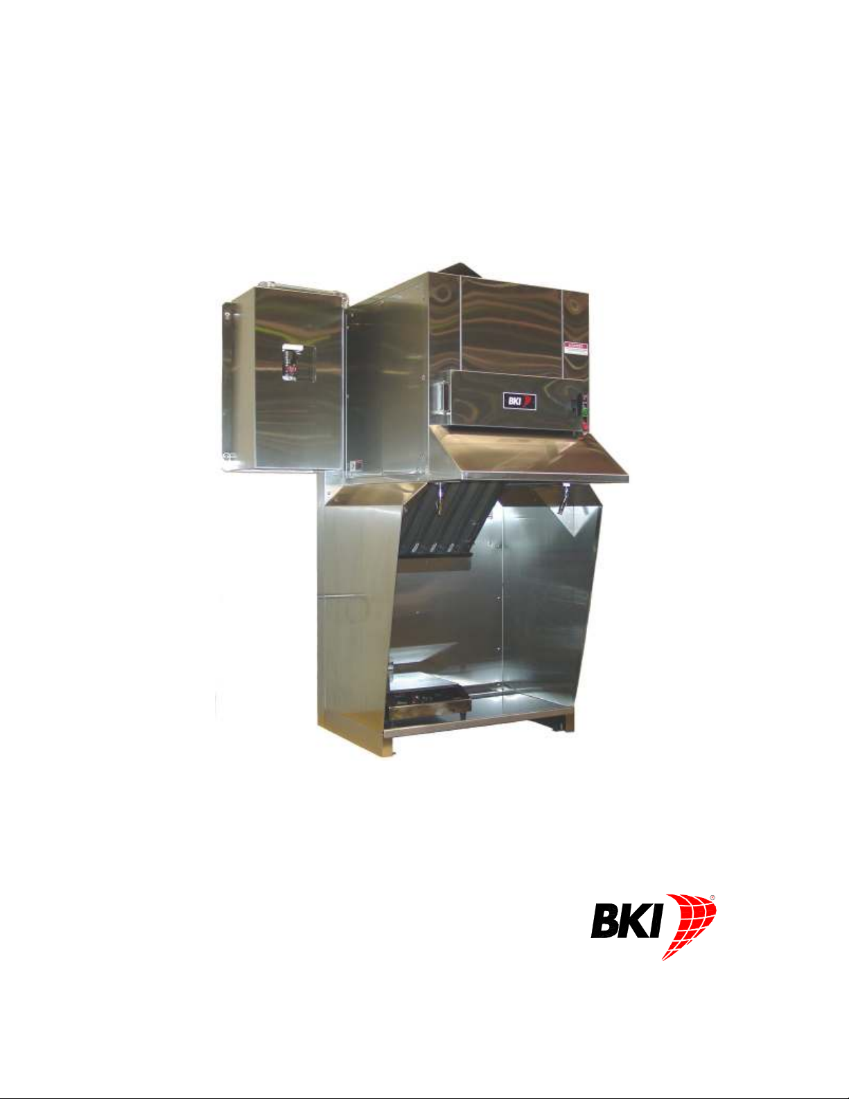
Ventless Hood System
MODEL FH-28CT COUNTERTOP
Service Manual
CS-TM-041.01 Revised 04/17/13
Page 2

(864) 963-3471 • Toll Free: (800) 927-6887 • Fax: (864) 963-5316
WHAT IS
WHO IS
COVERAGE PERIOD
WARRANTY COVERAGE
EXCEPTIONS
EXCLUSIONS
INSTALLATION
REPLACEMENT PARTS
date of
COVERED
COVERED
installation
by a BKI F
BKI LIMITED W ARRANTY
2812 Grandview Dr. • Simpsonville, SC 29680 • USA
This warranty covers defects in material and workmanship under normal use, and applies
only to the original purchaser providing that:
The equipment has not been accidentally or intentionally damaged, altered or misused;
The equipment is properly installed, adjusted, operated and maintained in accordance
national and local codes, and in accordance with the installation and operating
with
instructions provided with this product.
The serial number rating plate affixed to the equipment has not been defaced or
removed.
This
equipment purchased
Warranty claims must be received in writing by BKI within one (1) year from
date of installation or within one (1) year and three (3) months from data of
shipment from the factory, whichever comes first.
COB Models: One (1) Year limited parts and labor.
COM Models: Two (2) Year limited parts and labor. COM convection ovens also have
a two (2) year door warranty.
CO1 Models: Two (2) Year limited parts and labor. Five (5) Year limited door
warranty.
BevLes Products: Two (2) Year limited parts and labor.
Warranty period begins the date of dealer invoice to customer or ninety (90) days
after shipment date from BKI, whichever comes first.
This
warranty
xpenses
e
hours
travel time and
extended door warranty on convection ovens years 3 through 5 is a parts only warranty and
does not include labor, travel, mileage or any other charges.
Thermostat calibrations
Air and gas
Light
Glass doors and
Fuses,
Adjustments
Tightening
Failures
Unauthorized
Damage
Alteration,
Thermostats
Freight –
Ordinary
Failure to follow
Events
appropriate installation
per
installer, not the
BKI genuine
actory Authorized
warranty
covers on-site labor, parts and
of the
Any exceptions must be pre-approved in advance and in writing by BKI. The
Negligence
adjustments,
bulbs,
of screws or
caused
in
shipment,
misuse or
and safety valves with
other than normal UPS charges,
wear and
beyond control
Leveling, as well as
manufacturer.
Factory OEM parts receive a (90) day
is
extended
for use in the U.S.A.
authorized
door adjustments,
to
burner
by erratic
repair by
installation and/or operating instructions,
Service
service
performed during regular, weekday business hours.
or acts of
after (30) days
flames and
fasteners,
voltages
anyone other than
improper installation,
tear,
of the
company.
proper installation
and use materials – is the responsibility of the
Center.
to the original
representative
God,
from equipment installation date,
cleaning of
or gas
broken
purchaser
reasonable
suppliers,
a BKI F
capillary tubes,
and check out of all
travel
up to (100) miles
pilot
burners,
actory Authorized
materials warranty
and applies only to
time
and travel
round
trip and (2)
Service Center,
new equipment -
dealer
effective from the
or
CS-TM-041.01 Revised 04/17/13
Page 3

Ventless Hood System Table of Contents
Table of Contents
Table of Contents ........................................................................................................................................1
Introduction..................................................................................................................................................2
Safety Precautions ....................................................................................................................................2
Safety Signs and Messages .................................................................................................................2
Specific Precautions .............................................................................................................................2
Safe Work Practices .............................................................................................................................3
Safety Labels ........................................................................................................................................4
Hood Specifications ..................................................................................................................................4
Cooktop Specifications..............................................................................................................................4
Installation....................................................................................................................................................5
Unpacking and Handling ...........................................................................................................................5
Inspection for Shipping Damage...........................................................................................................5
Location and Clearance ........................................................................................................................5
Assembly and Mounting ............................................................................................................................5
Hood Mounting......................................................................................................................................5
Particle/Odor Filter ................................................................................................................................6
Fire Damper ..........................................................................................................................................6
Air Deflector ..........................................................................................................................................7
Fire Extinguishing System ....................................................................................................................7
Wiring ......................................................................................................................................................15
Maintenance ...............................................................................................................................................18
Scheduled Maintenance..........................................................................................................................18
Cleaning the Grease Baffle.................................................................................................................19
Replacing the Particle/Odor Filter.......................................................................................................19
Replacement Parts ....................................................................................................................................20
Wiring Diagrams ........................................................................................................................................26
Notes...........................................................................................................................................................27
1
Page 4
Ventless Hood System Introduction
Introduction
Congratulations! You have chosen BKI’s Ventless Hood system, a state-of-the-art unit that filters grease
laden air and returns it to the room.
The BKI name and trademark on this unit assures you of the finest in design and engineering -- that it has
been built with care and dedication -- using the best materials available. Attention to the operating
instructions regarding proper operation, installation and maintenance will result in long lasting
dependability to insure the highest profitable return on your investment.
PLEASE READ THIS ENTIRE MANUAL BEFORE OPERATING THE UNIT. If you
have any questions, please contact your BKI Distributor. If they do not answer
your questions, contact the BKI Technical Service Department, toll free: 1-800927-6887. Outside the U.S., call 1-864-963-3471.
Safety Precautions
Always follow recommended safety precautions listed in this manual. Below is the safety alert symbol.
When you see this symbol on your equipment, be alert to the potential for personal injury or property
damage.
Safety Signs and Messages
The following Safety signs and messages are placed in this manual to provide instructions and identify
specific areas where potential hazards exist and special precautions should be taken. Know and
understand the meaning of these instructions, signs, and messages. Damage to the equipment, death or
serious injury to you or other persons may result if these messages are not followed.
This message indicates an imminently hazardous situation, which, if not avoided,
will result in death or serious injury.
This message indicates a potentially hazardous situation, which, if not avoided,
could result in death or serious injury.
This message indicates a potentially hazardous situation, which, if not avoided,
may result in minor or moderate injury. It may also be used to alert against unsafe
practices.
This message is used when special information, instructions or identification are
required relating to procedures, equipment, tools, capacities and other special
data.
Specific Precautions
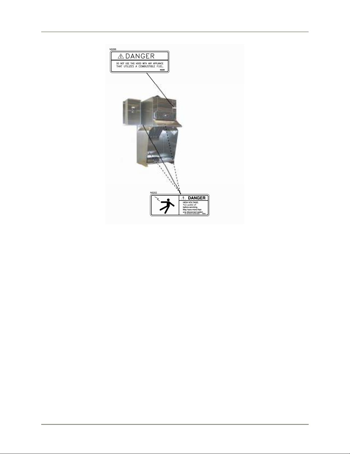
Carbon monoxide poisoning will result from using this hood with any appliance
that utilizes combustible fuel. Use only electrical appliances with this hood.
Hood failure could result if the hood is operated without the grease baffle and
particle/odor filter installed. This is a special filter designed for this application
only; other filters will not work properly. Use only a BKI particle/odor filter.
2
Page 5
Ventless Hood System Introduction
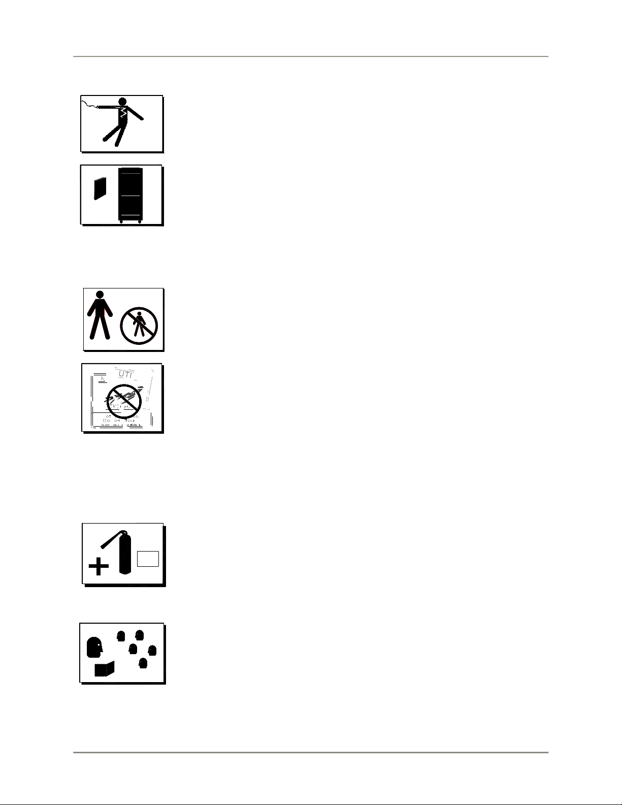
Safe Work Practices
Beware of High Voltage
This equipment uses high voltage. Serious injury can occur if you or any
untrained or unauthorized person installs, services, or repairs this equipment.
Always Use an Authorized Service agent to Service Your Equipment
Keep this manual with the Equipment
This manual is an important part of your equipment. Always keep it near for easy
access. If you need to replace this manual, contact:
BKI
Technical Services Department
2812 Grandview Drive
Simpsonville, S.C. 29680
Or call toll free: 1-800-927-6887
Outside the U.S., call 864-963-3471
Protect Children
Keep children away from this equipment. Children may not understand that this
equipment is dangerous for them and others.
NEVER allow children to play near or operate your equipment.
Keep Safety Labels Clean and in Good Condition
Do not remove or cover any safety labels on your equipment. Keep all safety
labels clean and in good condition. Replace any damaged or missing safety
labels. Refer to the Safety Labels section for illustration and location of safety
labels on this unit. If you need a new safety label, obtain the number of the
specific label illustrated on page 4, then contact:
BKI
Technical Services Department
2812 Grandview Drive
Simpsonville, S.C. 29680
Or call toll free: 1-800-927-6887
Outside the U.S., call 864-963-3471
Prepare for Emergencies
Be prepared for fires, injuries, or other emergencies.
911
Keep a first aid kit and a fire extinguisher near the equipment. You must use a
40-pound Type BC fire extinguisher and keep it within 25 feet of your equipment.
Keep emergency numbers for doctors, ambulance services, hospitals, and the
fire departments near your telephone.
Know your responsibility as an Employer
• Make certain your employees know how to operate the equipment.
• Make certain your employees are aware of the safety precautions on the
equipment and in this manual.
• Make certain that you have thoroughly trained your employees about
operating the equipment safely.
• Make certain the equipment is in proper working condition. If you make
unauthorized modifications to the equipment, you will reduce the safety and
function of the equipment.
3
Page 6
Ventless Hood System Introduction
Safety Labels
Hood Specifications
Power 208/120V or 240/120V (Neutral wire required)
Phase 1 or 3 (see wiring instructions)
Hood Blower Motor 1/2 HP
Fuse or Breaker size 40A
Wire Size Minimum recommended wire size for all leads and neutral is 8 ga.
Note: Above specifications include the load of 4 cooktop appliances (1.5KW) powered by the hood.
Cooktop Specifications
Volts 120V
Phase 1
Maximum Amps 12.5A
Maximum Input 1500W
Frequency 60 Hz
Maximum combined cooking surface area 450 sq. in. (2903 sq. cm.)
Maximum cooking surface temperature
USE UL LISTED APPLIANCES ONLY
450° F. (232° C.)
4
Page 7
Ventless Hood System Installation
Installation
Unpacking and Handling
Inspection for Shipping Damage
YOU are responsible for filing all freight claims with the delivering truck line. Inspect all cartons and crates
for damage as soon as they arrive. If damage to cartons or pallets is found, or if a shortage is found, note
this on the bill of lading (all copies) prior to signing and receiving.
If damage is found when the equipment is opened, immediately call the delivering truck line and follow up
the call with a written report indicating concealed damage to your shipment. Ask for an immediate
inspection of your concealed damage item. Packaging material MUST be retained to show the inspector
from the shipping line.
Location and Clearance
Place the Filter Hood in a location with clearance as shown below. These distances provide for proper
clearance to combustible surfaces, access for maintenance, and proper air flow from hood exit vent.
MINIMUM CLEARANCE HOOD TO
COMBUSTIBLE 18 in. (FH-28) SIDES, 0 in.
BACK, 0 in. TOP, 0 in. BOTTOM
APPLIANCE CLEARANCE Cooking surface
must be at least 3.5 inches behind the front edge
of the hood.
Assembly and Mounting
Hood Mounting
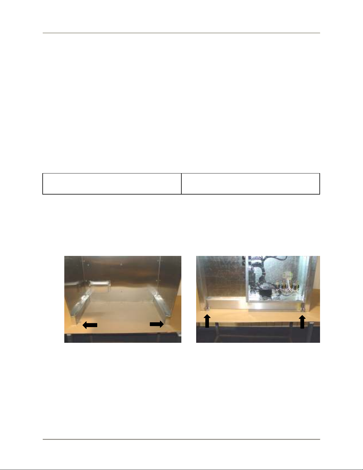
1. Assemble the hood to the table using four 1/4” x 20 bolts (3/4” long) and lock washers. Mounting
brackets are fixed to the support legs as shown below.
Front Mounting Brackets Rear Mounting Brackets
2. Seal the hood base to unit using NSF approved silicone rubber sealant.
5
Page 8
Ventless Hood System Installation
3. Place the appliance shelf under the hood as shown below.
Particle/Odor Filter
1. Remove the filter from the plastic bag.
2. Open the filter door on the front of the unit by rotating the handle counter-clockwise.
3. Observing the “UP” arrows on the filter, with a hand at each front corner, carefully slide the filter
into the unit.
4. Close and latch the door.
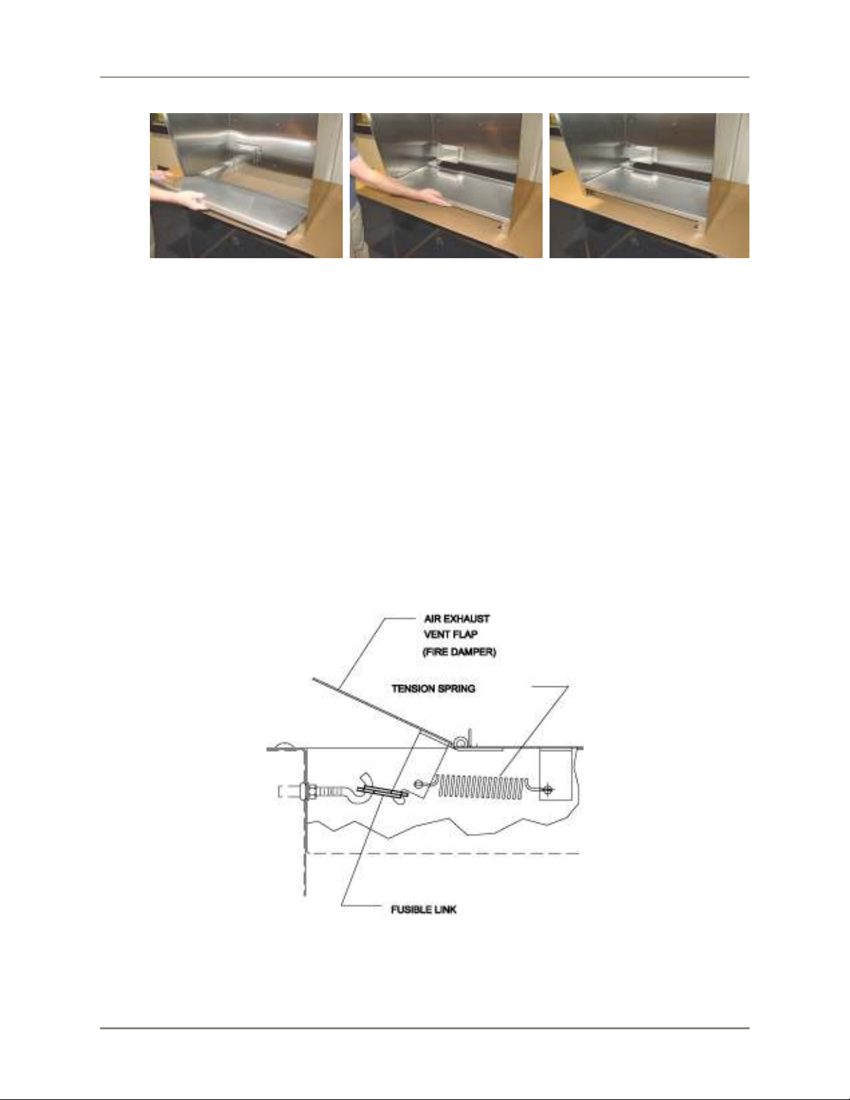
Fire Damper
A UL Listed 165° F fusible link must be installed in the damper assembly located at the top of the unit.
Install as follows:
1. Lift the damper.
2. Place the link on the damper hook.
3. Lower the damper while placing the link onto the stationary hook.
6
Page 9
Ventless Hood System Installation
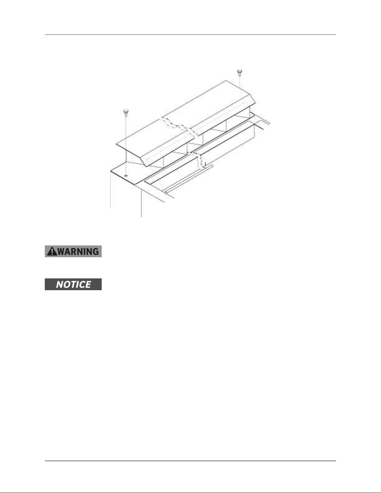
Air Deflector
Mount air deflector, as shown in the figure below, using two knurled screws (provided).
Fire Extinguishing System
In the event of an appliance fire, serious injury, property damage or death could
occur if any part of the appliance obstructs the spray nozzles. Ensure that lids
and/or other parts of the appliance do not obstruct the spray pattern of either
nozzle.
The fire extinguishing system components used in this hood have been
evaluated by U.L. in the course of their classification for use on this hood.
An authorized Range Guard distributor must install and activate the filter hood
fire extinguishing system. To locate an authorized Range Guard Distributor use
the following contact information:
Ronald Woodward
Technical Service Specialist
Badger Fire Protection
4251 Seminole Trail
Charlottesville Va. 22911
Office: 800-446-3857 ext. 111
Fax: 434-974-4113
Mobile: 434-981-0505
7
Page 10

Ventless Hood System Installation
1. Mount the fire extinguisher control as follows:
a. When viewed from the front of the hood, mount the fire extinguisher control/cylinder plate to
right hand side of hood (see Figure 1) when hood is mounted on left end of table or to left
side of hood (see Figure 2) when hood is mounted on right end of table. Use (2) ¼-20x3/4”
bolts and lockwashers to secure plate to rear of hood frame.
b. Attach cylinder actuator and discharge fitting assembly cylinder.
c. Mount cylinder on bracket.
d. Attach 8” nipple, 17.5” nipple, 90° ells, and union/vent assembly as shown in Figure 1 or
Figure 2. It may be necessary to rotate the union and elbow 180° to attach to cylinder union.
e. Attach conduit lengths and corner pulleys to A+ control box as shown in Figure 1 or Figure 2
simultaneously routing cable per standard Range Guard procedures.
f. Route flexible conduit as shown to top of A+ control box.
g. Connect microswitch interlock to hood electrical wires per wiring diagram provided in this
manual. Refer to the electrical diagram included in this manual (see page 26).
2. Mount the Pull Station as follows:
a. Remove protective plastic from all parts.
b. Mount remote pull box to remote pull enclosure bottom using (2) ¼-20x ¾ bolts,
lockwashers, and nuts.
c. Mount remote pull mounting plate to side of table using hardware provided with table.
d. Refer to in Figure 3 or Figure 4. Attach remote pull enclosure bottom to inside of mounting
plate using (6) #10 sheetmetal screws.
e. Attach conduit lengths and corner pulleys to remote pull box as shown in Figure 3 or Figure 4
simultaneously routing cable per standard Range Guard procedures.
f. Attach remote pull enclosure top to mount plate and enclosure bottom using (8) #10
sheetmetal screws.
h. Mount remote pull cover plate. Refer to Figure 5 for complete pull station mounting.
8
Page 11

Ventless Hood System Installation
Figure 1
9
Page 12

Ventless Hood System Installation
Figure 2
10
Page 13

Ventless Hood System Installation
Figure 3. Right Side Pull Station Mounting
11
Page 14

Ventless Hood System Installation
Figure 4. Left Side Pull Station Mounting
12
Page 15

Ventless Hood System Installation
Figure 5. Complete Pull Station Mounting
13
Page 16

Ventless Hood System Installation
FUSIBLE
3. If required, connect the provided fire extinguishing system contacts for remote signaling. Refer to
the electrical diagram included in this manual (see page 26).
4. Adjust the position of the two ADP appliance nozzles as depicted below.
5. Install two UL Listed; type “A”, 165° F. fusible links (load rating 3-45 lbs.) in the two appliance
detector positions (one in front of the grease baffle, one behind the grease baffle).
LINKS
14
Page 17

Ventless Hood System Installation
6. Reset control head. With control head NOT installed on cylinder, dry test system by activating the
remote pull.
7. Reset control head and activate system per Range Guard procedures.
8. Recheck installation procedure to insure that nothing has been overlooked.
Wiring
Electrocution, equipment failure or property damage could result if an unlicensed
electrician performs the electrical installation. Ensure that a licensed
electrician performs the electrical installation using appropriate materials
and construction practices which conform to the National Electric Code
and all local codes.
In the event of an appliance fire, serious injury, property damage or death could
occur if the appliance is powered from a source other than the hood. The cooking
appliance used under this hood MUST receive its input power from the hood. In
the event of a fire, the hood fire extinguishing system will automatically remove
power from the connected appliance.
The fire extinguishing system must be operative before the electrical system will
function.
Refer to the electrical diagram included in this manual (see page 26).
The hood may be connected to either a 208/120V or a 240/120V supply. The supply may be either 3
phase or 1 phase. The hood as supplied, is connected for single phase operation. When a three phase
supply is available, it can be internally reconnected for three phase operation to balance load. Refer to
the directions on the hood wiring diagram. (see page 26).
Connection to the hood electrical box can be made using either flexible conduit, or a cord/plug
combination. One-inch knockouts are provided in the top and the bottom of the electrical box. A ground
wire and a separate neutral wire MUST be provided for all connections. The minimum recommended wire
size is 8ga. The circuit protection device should be sized at 40 amperes. The hood/table system should
be restrained to avoid any stress on the conduit or cord connecting the appliance when the system is
moved for cleaning. Insure that cords or conduit are properly secured as to avoid any physical damage
from covers, edges, etc. when the unit is moved.
1. Connect incoming power as follows:
• For single-phase operation, connect incoming power to terminals L1 and L2 of the contactor.
Connect neutral and ground as shown in Figure 6.
• For three-phase operation, connect incoming power to terminals L1, L2 and L3 of the
contactor. Reconnect second receptacle inside hood electrical box to T2 and T3 on 1CR.
Connect neutral and ground as shown in Figure 6.
2. Insure that the fire extinguishing control box microswitch has been properly connected. Refer to
1g on page 8.
15
Page 18

Ventless Hood System Installation
1 RECPT.
2 RECPT.
3 RECPT.
4 RECPT.
1FU
3FU
1CB
2CB
2FU
4FU
3CB
4CB
3. Place circuit breakers 1CB thru 4CB in the ON position.
Wiring may become damaged from wear if straight plugs are used. Appliances
must have right angle plugs to properly fit under receptacle cover.
4. Insert plug into receptacles located in the hood.
16
Page 19

Ventless Hood System Installation
5. Install the cover over the appliance receptacles as shown.
6. Install rear cover on the back of the hood as shown. The cover installs on 4 posts located inside
the frame
Note: To remove the rear cover, lift and pull toward you.
17
Page 20

Ventless Hood System Maintenance
Maintenance
Electrocution could occur if this unit is hosed down with water. This unit is NOT
designed for hose wash-down cleaning! Refer to scheduled maintenance below
for proper hood cleaning.
Electrocution could occur if power is not removed from this unit before servicing.
Remove power at disconnect or circuit breaker BEFORE servicing hood.
Scheduled Maintenance
Use the following table to help manage scheduled maintenance activities.
FREQUENCY PERFORMED BY PART ACTIVITY
Daily
User Condensation
User Grease Baffle Clean grease baffle. If necessary, refer
Weekly
Monthly
3 Months
User Entire Hood Wipe unit down with a soft rag and mild
cleaning agent.
Check condensation trough. Empty if
trough
User Particle/Odor Filter Inspect particle/odor filter. In low to
User Door and Filter
Interlock
Injury from rotating fan blades could occur if power is not removed from this unit
before cleaning the blower section. Remove power at disconnect or circuit breaker
BEFORE cleaning the blower section.
User Blower Section Clean the blower section.
necessary.
to the procedure in this manual for
cleaning the baffle.
medium volume applications, the filter
may need replacement prior to the
indicating light turning on. This
condition will be evident by a strong
odor coming from the face of the filter.
If necessary, refer to the procedure in
this manual for replacing the filter.
Check door and filter interlock
operation. The unit should not operate
with the front door open or either the
grease baffle or particle/odor filter
removed. Clean area between grease
baffle and particle/odor filter.
6 Months
Authorized Service
agent
Fire Extinguishing
System
18
Have the fire extinguishing system
inspected.
Page 21

Ventless Hood System Maintenance
Cleaning the Grease Baffle
1. Shut down the unit.
2. Locate the thumbscrews and retaining frame at the top of the grease baffle.
3. With one hand, hold the baffle to prevent it from dropping. With the other hand, loosen the
thumbscrews and slide the retaining frame forward.
4. Slowly lower the top end of the baffle until it clears the retaining frame.
5. Spray the grease baffle with degreasing type soap.
6. Rinse with hot water; dry, and replace in hood.
Replacing the Particle/Odor Filter
1. Shut down the unit.
2. Open the filter door on the front of the unit by rotating the handle counter-clockwise.
3. Slide the used filter out of the unit.
4. Remove the replacement filter from the plastic bag.
5. Observing the “UP” arrows on the filter, with a hand at each front corner, carefully slide the filter
into the unit.
When installing a new filter, slight resistance should be observed as the filter is
being slid into place. This resistance is generated by four (4) filter springs located
on the bottoms of the filter slides. These springs insure a proper seal at the top of
the filter. After a period of time it may become necessary to adjust the pressure
that these springs provide by lifting them slightly with your fingers.
6. Close and latch the door.
19
Page 22

Ventless Hood System Replacement Parts
Replacement Parts
Use the information in this section to identify replacement parts. To order replacement parts, call your
local BKI sales and service representative. Before calling, please note the serial number on the rating tag
affixed to the unit.
Description Figure #
Electrical Box Assembly 6
Blower Motor Assembly 7
Right Side Cabinet Assembly 8
Figure 6. Electrical Box Assembly (Sheet 1 of 2)
20
Page 23

Ventless Hood System Replacement Parts
Figure 6. Electrical Box Assembly (Sheet 2 of 2)
ITEM # PART # QTY DESCRIPTION
1 WB37140100 1 ELECT.BOX WELDMENT FH-28CT
2 CB0066 4 BREAKER,CIR.W/LUGS 15A 120V 50/60HZ
3 F0100 2 FUSE, 1A 300V SC-1 TIME DELAY
4 FH0001 2 FUSE HOLDER, 15A 300V HPF-EE
5 F0336 2 FUSE, 5A 250V FNM5 TIME DELAY
6 FH0006 2 FUSE HOLDER, 30A 600V HPF
7 R0129 1 RELAY, 3POLE 60A 208/240 50/60
8 RC0017 4 RECEPTACLE, NEMA 5-15 FH-28CT
9 MB44023700 1 TB0045 RAIL CUT 2.813"
10 TB0046 2 TERM BLOCK, WDU10 #102030
11 TB0047 1 TERM BLOCK END PLATE WAP
12 TB0048 1 TERM BLOCK GROUND BLOCK
13 TB0049 1 TERM BLOCK 2 POLE JUMPER
14 TB0051 1 TERM BLOCK END BRKT EW35
21
Page 24

Ventless Hood System Replacement Parts
Figure 7. Blower Motor Assembly
22
Page 25

Ventless Hood System Replacement Parts
. Blower Motor Assembly – Continued
ITEM # PART # QTY DESCRIPTION
1 M0052 1 MOTOR, BLOWER 1/2 HP LEESON
2 F0024 16 RIVNUT, #10-24
3 TP0021 36” TAPE, ARMAFLEX 1/8 X 3/4 X 50'
4 WSH037 4 WASHER, 3/16 SAE FLAT
5 NUT049 8 NUT, 8-32 HEX
6 SP0013 4 SPACER, FOR #8 X 1/2" LG.
7 FN0005 1 HOUSING, BLOWER CLOCKWISE
8 FN0004
OR
FN0019
1
OR
1
WHEEL, BLOWER 5 3/4 CLKWS RT.
OR
BLOWER WHEEL, 50HZ FH HOODS
9 FB37115200 1 CONDUIT, 1/2" FT0323 10"
10 FT0320 2 COMPRESSION FTG, 1/2" STRAIGHT
11 FN0006
OR
FN0020
1
OR
1
WHEEL, BLOWER 5-3/4 CTCKWS LT
OR
BLOWER WHEEL, 50 HZ FH HOODS
12 FN0007 1 HOUSING, BLOWER C'TR CLK WISE
13 SCR004 6 SCREW, 8 X 3/8 PHIL TRUSS HD
14 FB37113602 1 PLATE, LEESON FAN MOUNTING
15 SCR137 8 SCREW, 10-24 X 5/8 SLTD TRUSS
23
Page 26

Ventless Hood System Replacement Parts
Figure 8. Right Side Cabinet Assembly
24
Page 27

Ventless Hood System Replacement Parts
Figure 8. Right Side Cabinet Assembly – Continued
ITEM # PART # QTY DESCRIPTION
1 S0097 1 SWITCH, VACUUM 371
2 S0098 1 SWITCH, VACUUM 371
3 S0099 1 SWITCH, VACUUM 371
4 S0101 1 SWITCH, VACUUM 371
5 PL0004 1 PILOT LIGHT, ROUND 250V
6 S0073 2 SWITCH, PUSHBUTTON MICRO
7 S0359
S0360
1
1
SWITCH, FLUSH GREEN PUSH ILLUM.
SWITCH, LAMP, LED, GREEN, 230V
8 S0307 1 SWITCH, NO BLOCK GE P9B10VN
9 S0311 1 SWITCH, EXTENDED RED PUSH
10 S0306 1 SWITCH, NC BLOCK GE P9B01VN
25
Page 28

Ventless Hood System Wiring Diagrams
Wiring Diagrams
26
Page 29

Ventless Hood System Notes
Notes
27
Page 30

2812 Grandview Dr., Simpsonville, S.C. 29680, USA
http://www.bkideas.com
Made and printed in the U.S.A
LI0205/0903
CS-TM-041.01 Revised 04/17/13
Page 31

Ventless Hood System Notes
REVISION HISTORY
REVISION
DATE REVISED BY DESCRIPTION
01 04/17/13 KW Initial Release-Supersedes all previous
releases
2
 Loading...